what is hvac - ibse - home - ibseibse.co.in/notes/hvac.pdf · 1 what is hvac hvac heating...
TRANSCRIPT
1
WHAT IS HVAC
HVAC
HEATING VENTILATION AIR CONDITIONING
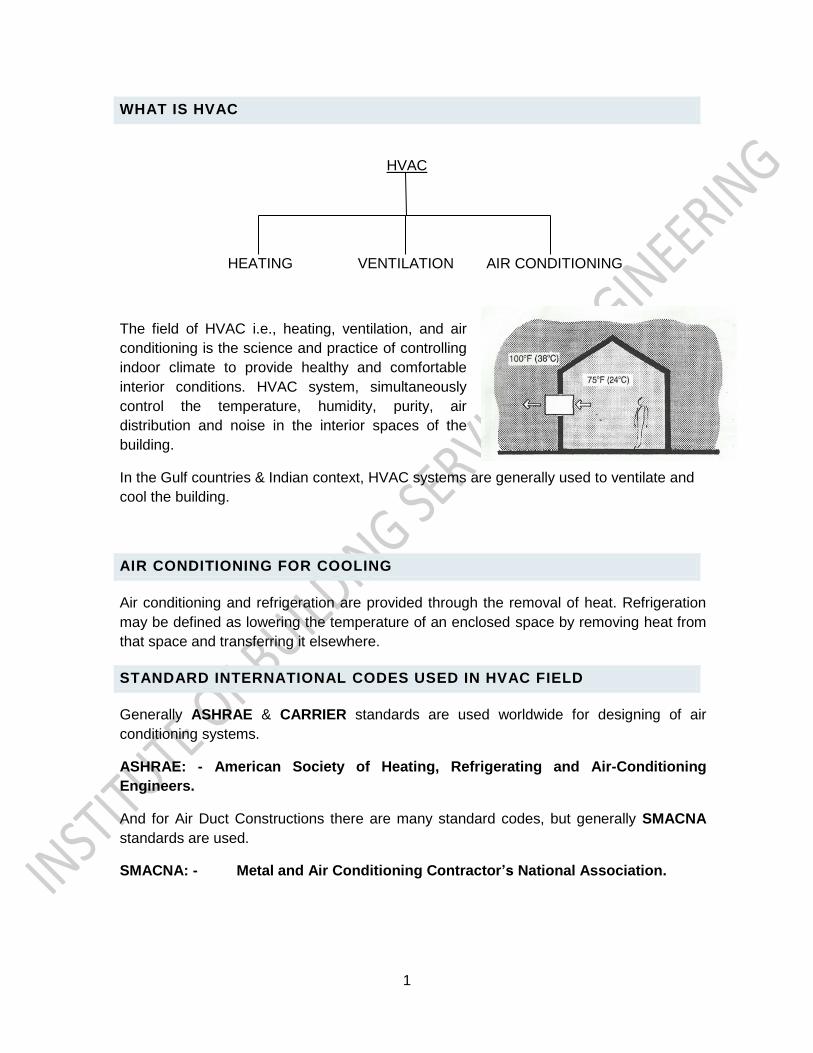
The field of HVAC i.e., heating, ventilation, and air
conditioning is the science and practice of controlling
indoor climate to provide healthy and comfortable
interior conditions. HVAC system, simultaneously
control the temperature, humidity, purity, air
distribution and noise in the interior spaces of the
building.
In the Gulf countries & Indian context, HVAC systems are generally used to ventilate and
cool the building.
AIR CONDITIONING FOR COOLING
Air conditioning and refrigeration are provided through the removal of heat. Refrigeration
may be defined as lowering the temperature of an enclosed space by removing heat from
that space and transferring it elsewhere.
STANDARD INTERNATIONAL CODES USED IN HVAC FIELD
Generally ASHRAE & CARRIER standards are used worldwide for designing of air
conditioning systems.
ASHRAE: - American Society of Heating, Refrigerating and Air-Conditioning
Engineers.
And for Air Duct Constructions there are many standard codes, but generally SMACNA
standards are used.
SMACNA: - Sheet Metal and Air Conditioning Contractor’s National Association.
2
FACTORS TO BE CONTROLLED IN AIR CONDITIONING PROCESS
Below are the factors has to be controlled by air conditioning process:-
1. Temperature
2. Humidity
3. Purity
4. Air distribution
5. Noise control
1.Temperature:-
Temperature measures the heat intensity or heat level of a substance. Temperature
alone does not give the amount of heat in a substance. It indicates the degree of
warmth, or how hot or cold the substance or body is. In the molecular theory of heat,
tempemture indicates the speed of motion of the molecules. Temperature is normally
measured by Thermometer.
Units of Temperature: - The two most common units of temperature are the, Fahrenheit
and the Celsius scales.
Converting 0C to 0F is:-
0C = 5/9 (0F-32)
&
Converting 0F to 0C is:-
0F = 9/5 (0C+32)
Dry-bulb temperature (DB): The dry-bulb temperature is the temperature of air
measured by a normal thermometer freely exposed to the air but shielded from radiation
and moisture. It is one of "the most important climate variables for human comfort and
building energy efficiency”.
Wet-bulb temperature (WB): The temperature registered by thermometer whose bulb
is covered by a wetted wick and exposed to a current of rapidly moving air. It is the
temperature air would have if part of its energy were used to evaporate the amount of
water it would absorb to become fully saturated.
3
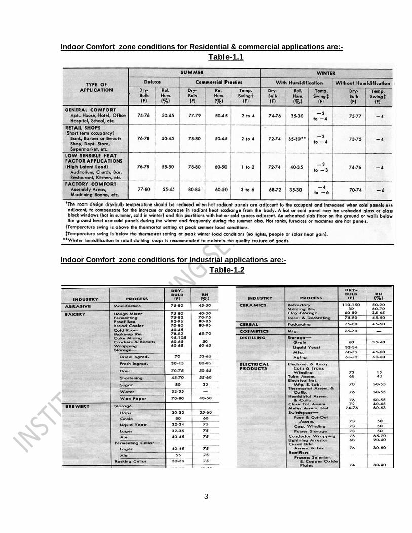
Indoor Comfort zone conditions for Residential & commercial applications are:-
Table-1.1
Indoor Comfort zone conditions for Industrial applications are:-
Table-1.2
4
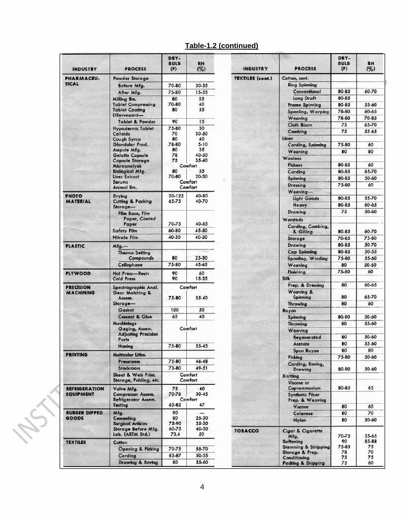
Table-1.2 (continued)
5
Table-1.2 (continued)
*And Out Door Design conditions data for designing of Air Conditioning systems are
generally extracted from Carrier or ASHRAE Design Handbook.
2.Humidity:-
Humidity is the Amount of water vapor present in a given space.
Absolute Humidity:-Density of water vapor per unit volume of air is absolute humidity
(AH)--expressed in units of lbs. of water/cu-ft of dry air.
Degree of saturation:- It is water present in air/max water vapor-holding capacity of air.
Relative humidity (RH) :- Relative humidity is the ratio of (actual vapor pressure of air-
vapor mixture/pressure of water vapor when the air is completely saturated at the same
DB temperature) x 100.
Human tolerance to humidity variations is much greater than temperature
variations. In winter, the range is from 20 to 50% of RH & in summer, the range
extends up to 60% @ 75ºF.
High humidity causes condensation problems and reduces body heat loss by
evaporative cooling.
6
Low humidity tends to dry throat and nasal passages also can cause static
electrical sparks.
And the standard indoor comfort levels of relative humidity for Residential, commercial &
industrial applications are given in TABLE-1.1 & TABLE-1.2.
*And Out Door Design conditions data for designing of Air Conditioning systems
are generally extracted from Carrier or ASHRAE Design Handbook.
3.Purity:-
It is the process of removing particulates (dust etc.) and biological contaminants,
(insects, pollen etc.) from the air delivered to the conditioned space for the purposes of
improving or maintaining the air quality.
Generally in air conditioning system filter are used for removing dust particulates & in
hospital HEPA (High-Efficiency Particulate Air) filters are used to filter the air which can
remove at least 99.97% of airborne particles. Please refer the picture below for a general
arrangement of an A/c Unit with Filter:-
A typical a/c unit arrangement
And for the treated Fresh air handling units Ultra violet air purifiers are used to kill the
bacteria & viruses from the air. Please refer Picture below:-
7
4. Air Distribution:-
It is the process of circulating and mixing air through conditioned spaces in the building
for the purposes of achieving the proper ventilation and facilitating the thermal energy
transfer.
Please refer picture below which shows a basic air distribution principle:-
5. Noise Control:-
Generally Noise can be controlled in ducted air conditioning systems. For small air
conditioning system Acoustic liners are used, which has to be lined inside duct surface &
has to be installed up to 1.5 meters from the discharge point or from mouth of the
machine. And the for the bigger capacity machines Sound attenuator are installed in
ducts to control the fan generated noise. Proper duct Design & selecting a proper air
outlets can control air borne noise. Standard Noise Criterions values are used to select
air outlets, please find the standard NC values in Table-1.3.
Sound Attenuator
8
Table-1.3 STANDARD NC VALUES
MODES OF HEAT TRANSFER
There are three modes of heat transfer, as Mentioned below:-
1. Conduction
2. Convection
3. Radiation
1. Conduction:- The transfer of heat through material is called Conduction. Example:-
heat travels from one end to other end of metal rod when it is heated. Heat always flows
from hot end to cold end.
A material which transfers heat easily is
called Conductors & materials which do
not conduct heat are called Insulators.
2. Convection:- This occurs in fluids
i.e. liquids & gases. When a material is
heated it expands the volume (i.e.
expansion in molecules) & it becomes
lighter & move upwards & it is replaced
by the colder ones. This is a continuous
effect. As shown in picture.
3. Radiation:- Heat transfers across
the space between two objects without any medium from one of which is higher in
9
temperature than the other. The best example of radiation is heat reaches from sun to
earth.
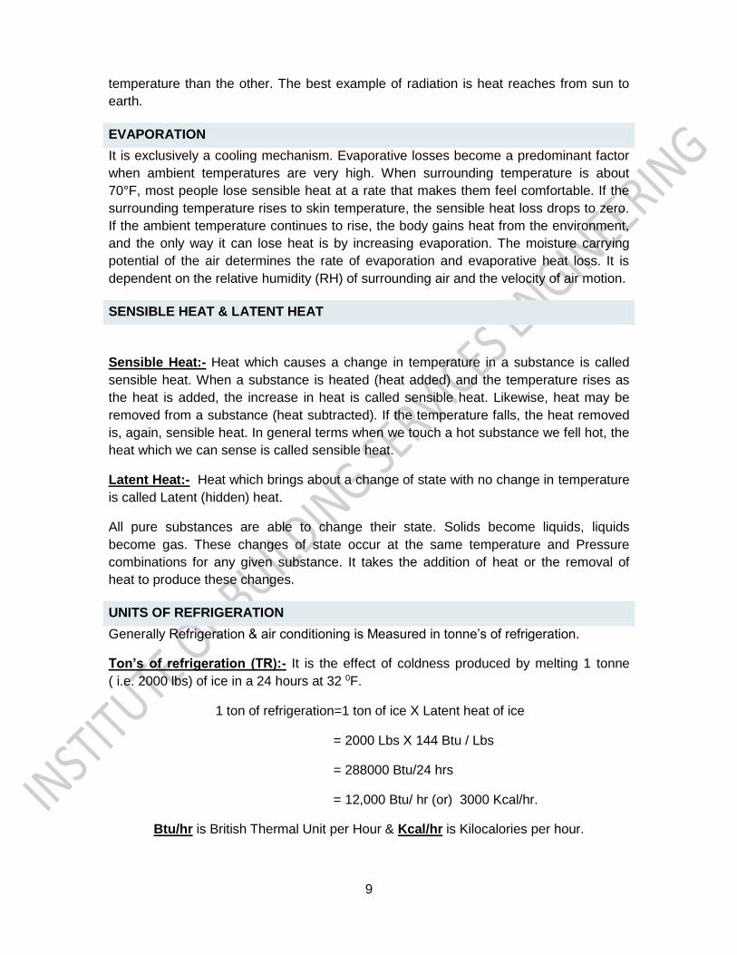
EVAPORATION
It is exclusively a cooling mechanism. Evaporative losses become a predominant factor
when ambient temperatures are very high. When surrounding temperature is about
70°F, most people lose sensible heat at a rate that makes them feel comfortable. If the
surrounding temperature rises to skin temperature, the sensible heat loss drops to zero.
If the ambient temperature continues to rise, the body gains heat from the environment,
and the only way it can lose heat is by increasing evaporation. The moisture carrying
potential of the air determines the rate of evaporation and evaporative heat loss. It is
dependent on the relative humidity (RH) of surrounding air and the velocity of air motion.
SENSIBLE HEAT & LATENT HEAT
Sensible Heat:- Heat which causes a change in temperature in a substance is called
sensible heat. When a substance is heated (heat added) and the temperature rises as
the heat is added, the increase in heat is called sensible heat. Likewise, heat may be
removed from a substance (heat subtracted). If the temperature falls, the heat removed
is, again, sensible heat. In general terms when we touch a hot substance we fell hot, the
heat which we can sense is called sensible heat.
Latent Heat:- Heat which brings about a change of state with no change in temperature
is called Latent (hidden) heat.
All pure substances are able to change their state. Solids become liquids, liquids
become gas. These changes of state occur at the same temperature and Pressure
combinations for any given substance. It takes the addition of heat or the removal of
heat to produce these changes.
UNITS OF REFRIGERATION
Generally Refrigeration & air conditioning is Measured in tonne’s of refrigeration.
Ton’s of refrigeration (TR):- It is the effect of coldness produced by melting 1 tonne
( i.e. 2000 lbs) of ice in a 24 hours at 32 0F.
1 ton of refrigeration=1 ton of ice X Latent heat of ice
= 2000 Lbs X 144 Btu / Lbs
= 288000 Btu/24 hrs
= 12,000 Btu/ hr (or) 3000 Kcal/hr.
Btu/hr is British Thermal Unit per Hour & Kcal/hr is Kilocalories per hour.
10
LAWS OF REFRIGERATION
• Fluids absorb heat while changing from a liquid to a vapor state.
• Fluids give up heat in changing from a vapor to a liquid.
• The temperature at which a change of state occurs is constant during the
change, providing pressure remains constant.
• Heat flows only from a body that is at higher temperature to a body that is at a
lower temperature (hot to cold).
• Metallic parts of the evaporating and condensing units use metals that have high
heat conductivity (copper, brass, aluminum).
• Heat energy and other forms of energy (electrical, mechanical) are
interchangeable.
REFRIGERANTS
Refrigerants are the liquids or chemicals used in refrigeration system.
Properties of refrigerants:-
• Nontoxic and nonpoisonous.
• Nonexplosive.
• Noncorrosive.
• Nonflammable.
• Make leaks easy to detect.
• Operate under low pressure (have a low boiling point).
• Must follow standards set by EPA (Environmental Protection Agency).
• Stable as a gas.
• Permit refrigerator or compressor parts moving in the fluid to be easily lubricated.
• Have a high liquid volume per pound.
• Have low vapor volume per pound.
• Have as little pressure difference as possible between evaporating pressure and
condensing pressure.
11
Classification of refrigerants:-
There are four classification of refrigerants based on the chemical composition, as listed
below:-
1. Chlorofluorocarbons (CFCs).
2. Hydro chlorofluorocarbons (HCFCs).
3. Hydro fluorocarbons (HFCs).
4. Refrigerant blends (azeotropic and zeotropic).
1.Chloroflurocarbons(CFCs):-
Chlorofluorocarbons (CFCs) are the First refrigerants to be developed. They are
composed of chlorine, fluorine, and carbon. They Low in toxicity and noncorrosive. And
even they are Nonflammable and nonexplosive (but should not be released where flame
or electric heating element is present). Heat causes CFCs to break down into their
elements, releasing compounds such as phosgene gas (extremely harmful to the
respiratory system). The Common CFCs include R-11, R-12, R-113, R-114, R-115, R-
500, R-502, and R-503. Chlorofluorocarbons (CFCs) are Believed to be major cause of
ozone depletion. By international agreement, not manufactured since 1995.
2. Hydrochlorofluorocarbons (HCFCs):-
Hydrochlorofluorocarbons (HCFCs) are molecules composed of methane or ethane in
combination with a halogen. This makes up a new molecule that is considered to be
partially halogenated.
The HCFCs have shorter lives and cause less ozone depletion than the fully
halogenated CFCs. Therefore, they have reduced potential for global warming. HCFCs
such as R-22 and R-123 are considered to be interim refrigerants. They will be used until
suitable replacements are available, the EPA requires the phase-out of HCFCs by the
year 2030.
3. Hydrofluorocarbons (HFCs):-
Hydrofluorocarbons (HFCs) include such refrigerants as R-134a and R-23. They are
different from chlorofluorocarbons—they contain one or more hydrogen atoms and no
chlorine atoms. HFCs are considered to have zero potential for ozone depletion. They
have only a slight effect on global warming.
4. Refrigerant blends (azeotropic and zeotropic) :-
Another more recent category is that of refrigerant blends, commonly referred to as
"azeotropic" and "zeotropic." The use of refrigerant blends is increasing. Azeotropic
blends do not change or separate in composition when used in refrigeration systems.
Zeotropic refrigerants are also blends comprised of various refrigerants. When used in a
refrigeration system, their volumetric composition and saturation temperature do change.
12
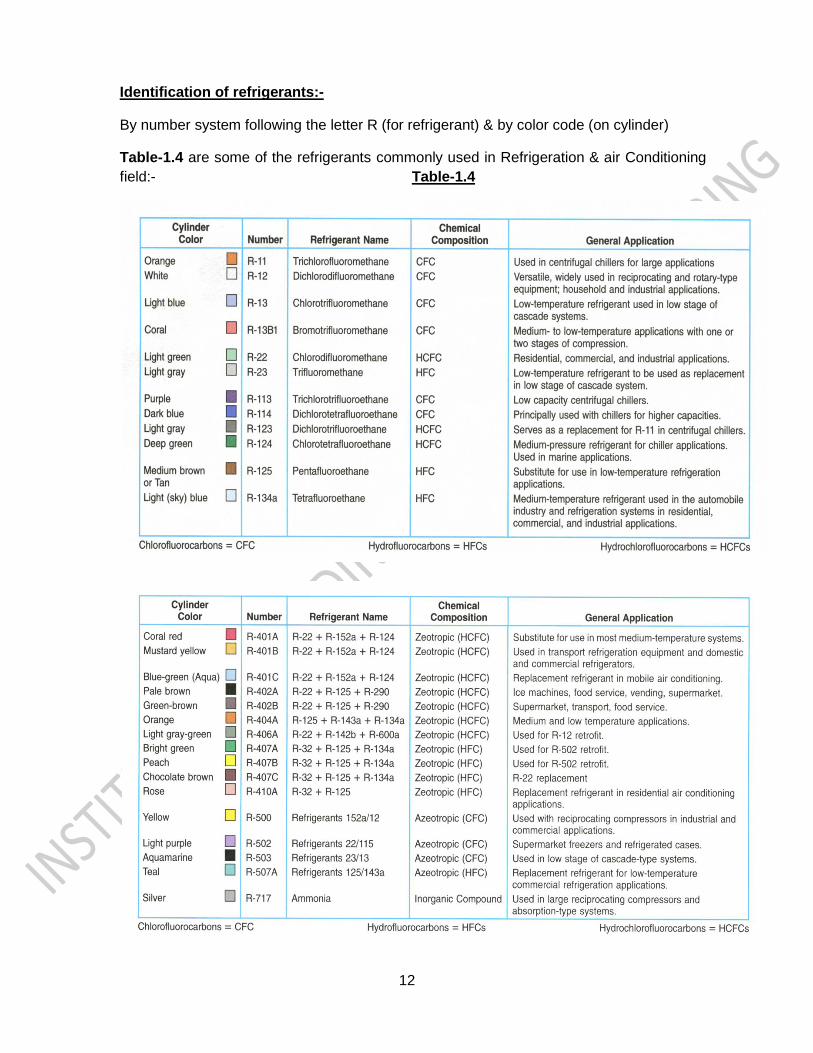
Identification of refrigerants:-
By number system following the letter R (for refrigerant) & by color code (on cylinder)
Table-1.4 are some of the refrigerants commonly used in Refrigeration & air Conditioning
field:- Table-1.4
13
METHODS OF REFRIGERATION CYCLES
There are two methods of refrigeration cycles used in Airconditioning field, as mentioned
below:-
1. Vapour Compression Refrigeration Cycle.
2. Vapour Absorption Refrigeration Cycle.
1.Vapour Compression Refrigeration Cycle :-
General overview of a Vapour Compression Refrigeration Cycle is, Hot compressed
vapour leaves a compressor & is liquified in a condenser by heat exchange with cooling
air or water. The liquid refrigerant then passes through an expansion device & the low
pressure liquid enters the evaporator. It absorbs the heat from the medium to be cooled
& the refrigerant is vaporized. The vapour enters the compressor and is raised to a
higher pressure & the cycle continues.
2.Vapour Absorption Refrigeration Cycle :-
General overview of a Vapour Absorption Refrigeration Cycle is, A solution of water in a
solvent is raised to a high pressure and heated which causes the dissolved water to
vaporise. The vapour is liquified in a condenser and then passes through an expansion
valve. Now at low pressure the water enters the evaporator, absorbs heat from the
medium to be cooled & vaporises. The vapour returns to be absorbed in the solvent.
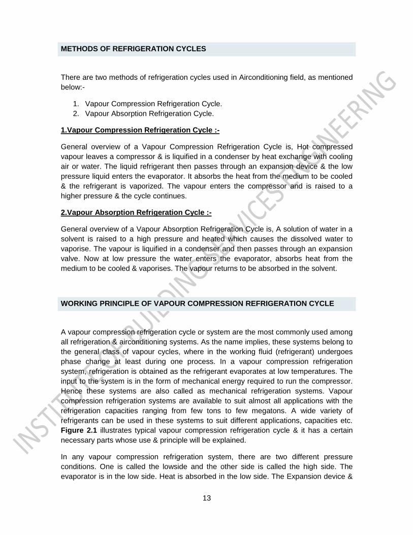
WORKING PRINCIPLE OF VAPOUR COMPRESSION REFRIGERATION CYCLE
A vapour compression refrigeration cycle or system are the most commonly used among
all refrigeration & airconditioning systems. As the name implies, these systems belong to
the general class of vapour cycles, where in the working fluid (refrigerant) undergoes
phase change at least during one process. In a vapour compression refrigeration
system, refrigeration is obtained as the refrigerant evaporates at low temperatures. The
input to the system is in the form of mechanical energy required to run the compressor.
Hence these systems are also called as mechanical refrigeration systems. Vapour
compression refrigeration systems are available to suit almost all applications with the
refrigeration capacities ranging from few tons to few megatons. A wide variety of
refrigerants can be used in these systems to suit different applications, capacities etc.
Figure 2.1 illustrates typical vapour compression refrigeration cycle & it has a certain
necessary parts whose use & principle will be explained.
In any vapour compression refrigeration system, there are two different pressure
conditions. One is called the lowside and the other side is called the high side. The
evaporator is in the low side. Heat is absorbed in the low side. The Expansion device &
14
suction line are also on the low side. The receiver or dryer, condensers in the high side.
This is where the heat is released from the refrigerant. The compressor is on the high
side.
FIGURE 2.1 - TYPICAL VAPOUR COMPRESSION REFRIGERATION CYCLE
15
As shown in figure 2.1 generally the process of vapour compression refrigeration cycle
is carried in four stages as listed below:-
1. Compression
2. Condensation
3. Expansion
4. Evaporation
Processes number as indicated in figure 2.1.
1.Compression:-
Under atmospheric temperature & pressure the refrigerant is in gaseous form. As we
know from the law of refrigeration that cooling takes place when liquids evaporates to
become gas. Therefore we must first transform the refrigerant gas into into liquid form.
Most gaseous can be made into liquids by raising its pressure & then cooling it. The
equipment that increases the pressure of the gas by compressing it is called the
Compressor. The compressor compresses the refrigerant in the gaseous state.
2.Condensation:-
During the process of compression however the refrigerant becomes hot. This is
because of the heat gain from the compressor due to work done. This heat has to be
removed to enable the gas to condense into a liquid easily. The equipment that removes
the heat called the condenser.
3.Expansion:-
Subsequently, the refrigerant in liquid form at high pressure flows through the expansion
valve, they are bundle of tubes (expansion or control device). The expansion valve is a
component fitted between the condenser and evaporator with the function of creating a
significant drop in pressure. This valve performs two functions: first of all, it ensures the
correct quantity of liquid refrigerant is sent to the evaporator, and in addition it creates a
pressure differential that is essential for the completion of the cycle.
The pressure differential is very important in a refrigerant circuit, as it changes the
boiling point of the fluid. Without this pressure change, no cooling would take place and
the system would simply be a container of liquid refrigerant.
4.Evaporation:-
Evaporation process is carried out in evaporator which is generally known as cooling
coil. Inside the cooling coil the pressure is low, because of the expansion device on one
side and the compressor suction on other side. In the low pressure, the liquid refrigerant
starts evaporating rapidly. While evaporating it needs sensible heat to transform itself
from the liquid to the gaseous state. So it soaks up heat from the surrounding tubes, and
from the air, with which the tubes are in contact. This causes the cooling.
16
This is end of the cycle & beginning of the next cycle, after the evaporation process is
done, the refrigerant is back in gaseous form. It is sucked into the compressor where it
will be compressed again for the next refrigeration cycle.
BASIC COMPENENTS OF AIRCONDITIONING & REFRIGERATION SYSTEM
A typical refrigeration system or an air conditioning system normally consists of several
basic components like,
1. compressors
2. condensers
3. expansion devices
4. evaporators
In addition to several accessories such as controls, filters, driers, oil separators etc. For
efficient operation of the refrigeration system, it is essential that there be a proper
matching between various components.
1.COMPRESSORS
A compressor is the most important and often the costliest component (typically 30 to 40
percent of total cost) of any vapour compression refrigeration system .Generally it is
called as Heart of refrigeration. Its function is to draw in the superheated gas refrigerant
arriving from the evaporator, compress it, and then deliver it to the condenser, where it
will become liquid again. The mechanical operation of the compressor implies an
increase in the heat contained in the vapour. The compression increases the pressure of
the vapour and consequently its temperature.
Types of Compressors:-
a.Based on working principle they are categorized into two types:
i. Positive Displacement Type
ii. Roto Dynamic Type
i. Positive Displacement Type:-
In positive displacement type compressors, compression is achieved by trapping a
refrigerant vapour into an enclosed space and then reducing its volume. Since a fixed
amount of refrigerant is trapped each time, its pressure rises as its volume is reduced.
When the pressure rises to a level that is slightly higher than the condensing pressure,
then it is expelled from the enclosed space and a fresh charge of low-pressure
refrigerant is drawn in and the cycle continues.
17
Depending upon the construction, positive displacement type compressors used in
refrigeration and air conditioning can be classified into:
i. Reciprocating type
ii. Rotary type with sliding vanes
iii. Rotary screw type
iv. Rotary Scroll type
ii. Roto Dynamic Type:-
In roto-dynamic compressors, the pressure rise of refrigerant is achieved by imparting
kinetic energy to a steadily flowing stream of refrigerant by a rotating mechanical
element and then converting into pressure as the refrigerant flows through a diverging
passage.
Depending upon the construction, roto-dynamic type compressors can be classified into:
i. Radial flow type or Axial flow type
Centrifugal compressors are radial flow type and are roto-dynamic compressors. And
these compressors are also known as turbo-compressors. These compressors are
widely used in large capacity refrigeration and air conditioning systems. This type of
compressor is used for high and very high cooling capacities.
b) Based on arrangement of compressor & motor or external drive ( Mechanical &
electrical power):
i. Open type
ii. Hermetically sealed type
iii. Semi-hermetically sealed type
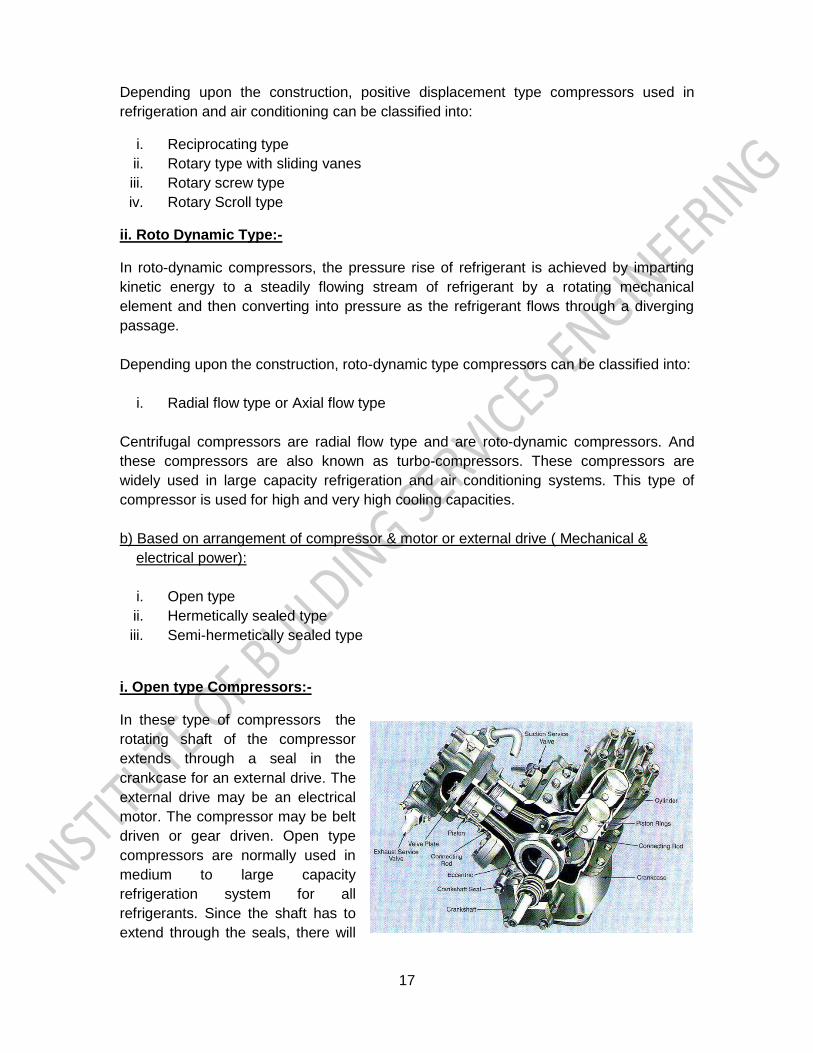
i. Open type Compressors:-
In these type of compressors the
rotating shaft of the compressor
extends through a seal in the
crankcase for an external drive. The
external drive may be an electrical
motor. The compressor may be belt
driven or gear driven. Open type
compressors are normally used in
medium to large capacity
refrigeration system for all
refrigerants. Since the shaft has to
extend through the seals, there will
18
be wear & tear of seals, because of that there will be leakage of refrigerant from the
system which cannot be eliminated completely. Therefore refrigeration systems using
these type compressors require a refrigerant reservoir to maintain the level of the
refrigerant in the system for some time, and they need a regular maintenance like
charging the system with refrigerant, changing of seals, gaskets etc.
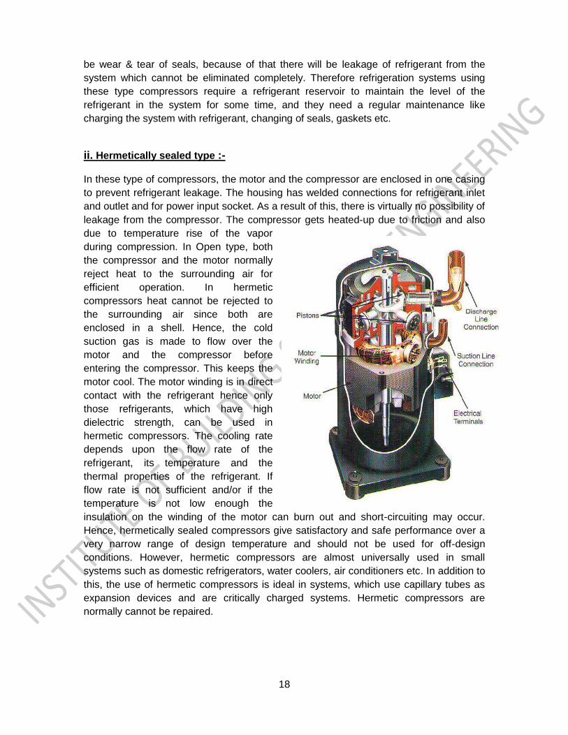
ii. Hermetically sealed type :- In these type of compressors, the motor and the compressor are enclosed in one casing
to prevent refrigerant leakage. The housing has welded connections for refrigerant inlet
and outlet and for power input socket. As a result of this, there is virtually no possibility of
leakage from the compressor. The compressor gets heated-up due to friction and also
due to temperature rise of the vapor
during compression. In Open type, both
the compressor and the motor normally
reject heat to the surrounding air for
efficient operation. In hermetic
compressors heat cannot be rejected to
the surrounding air since both are
enclosed in a shell. Hence, the cold
suction gas is made to flow over the
motor and the compressor before
entering the compressor. This keeps the
motor cool. The motor winding is in direct
contact with the refrigerant hence only
those refrigerants, which have high
dielectric strength, can be used in
hermetic compressors. The cooling rate
depends upon the flow rate of the
refrigerant, its temperature and the
thermal properties of the refrigerant. If
flow rate is not sufficient and/or if the
temperature is not low enough the
insulation on the winding of the motor can burn out and short-circuiting may occur.
Hence, hermetically sealed compressors give satisfactory and safe performance over a
very narrow range of design temperature and should not be used for off-design
conditions. However, hermetic compressors are almost universally used in small
systems such as domestic refrigerators, water coolers, air conditioners etc. In addition to
this, the use of hermetic compressors is ideal in systems, which use capillary tubes as
expansion devices and are critically charged systems. Hermetic compressors are
normally cannot be repaired.
19
iii. Semi-Hermetically sealed type :- The alternative to the hermetic compressor is the semi-hermetic compressor. These are
similar in design but have one significant difference. In semi hermetic compressors the
casing for the unit is not welded, but is instead sealed gasketed covers.
The advantages of semi-hermetically sealed compressors are, when a component
breaks, the unit can be opened up and individual pieces replaced, that’s why this type of
compressors are preferable than hermetically sealed compressors.
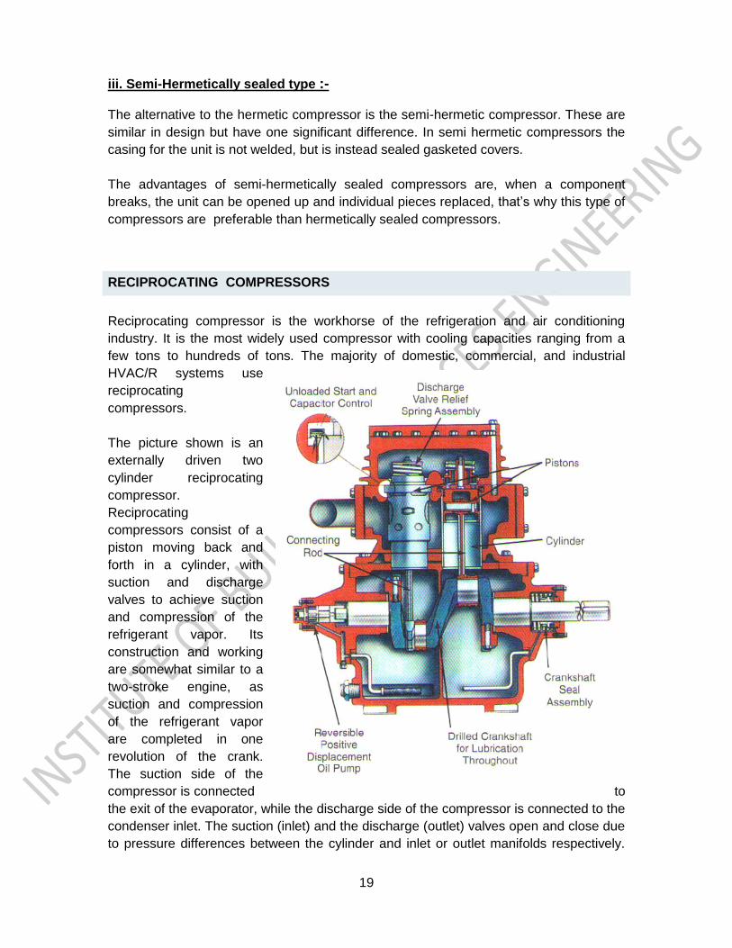
RECIPROCATING COMPRESSORS
Reciprocating compressor is the workhorse of the refrigeration and air conditioning
industry. It is the most widely used compressor with cooling capacities ranging from a
few tons to hundreds of tons. The majority of domestic, commercial, and industrial
HVAC/R systems use
reciprocating
compressors.
The picture shown is an
externally driven two
cylinder reciprocating
compressor.
Reciprocating
compressors consist of a
piston moving back and
forth in a cylinder, with
suction and discharge
valves to achieve suction
and compression of the
refrigerant vapor. Its
construction and working
are somewhat similar to a
two-stroke engine, as
suction and compression
of the refrigerant vapor
are completed in one
revolution of the crank.
The suction side of the
compressor is connected to
the exit of the evaporator, while the discharge side of the compressor is connected to the
condenser inlet. The suction (inlet) and the discharge (outlet) valves open and close due
to pressure differences between the cylinder and inlet or outlet manifolds respectively.
20
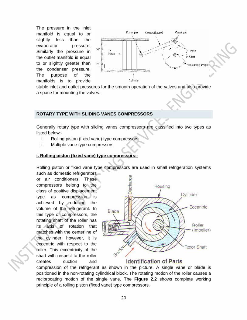
The pressure in the inlet
manifold is equal to or
slightly less than the
evaporator pressure.
Similarly the pressure in
the outlet manifold is equal
to or slightly greater than
the condenser pressure.
The purpose of the
manifolds is to provide
stable inlet and outlet pressures for the smooth operation of the valves and also provide
a space for mounting the valves.
ROTARY TYPE WITH SLIDING VANES COMPRESSORS
Generally rotary type with sliding vanes compressors are classified into two types as
listed below:-
i. Rolling piston (fixed vane) type compressors
ii. Multiple vane type compressors
i. Rolling piston (fixed vane) type compressors:-
Rolling piston or fixed vane type compressors are used in small refrigeration systems
such as domestic refrigerators
or air conditioners. These
compressors belong to the
class of positive displacement
type as compression is
achieved by reducing the
volume of the refrigerant. In
this type of compressors, the
rotating shaft of the roller has
its axis of rotation that
matches with the centerline of
the cylinder, however, it is
eccentric with respect to the
roller. This eccentricity of the
shaft with respect to the roller
creates suction and
compression of the refrigerant as shown in the picture. A single vane or blade is
positioned in the non-rotating cylindrical block. The rotating motion of the roller causes a
reciprocating motion of the single vane. The Figure 2.2 shows complete working
principle of a rolling piston (fixed vane) type compressors.
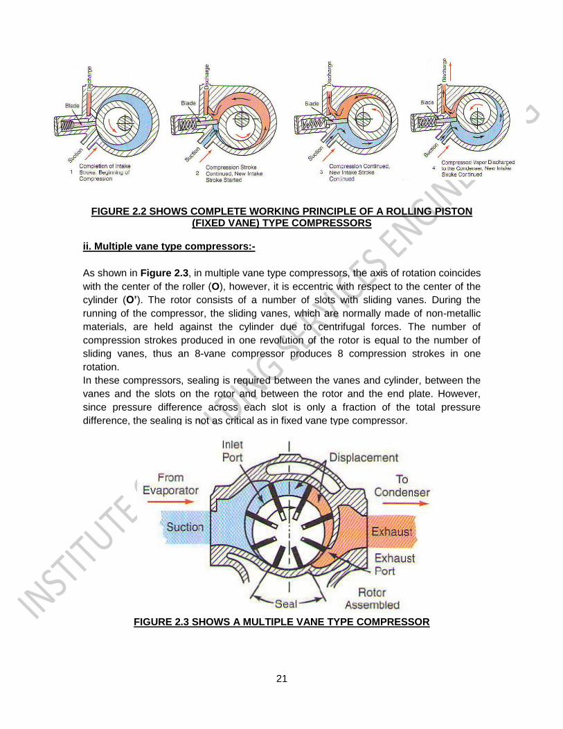
21
FIGURE 2.2 SHOWS COMPLETE WORKING PRINCIPLE OF A ROLLING PISTON
(FIXED VANE) TYPE COMPRESSORS
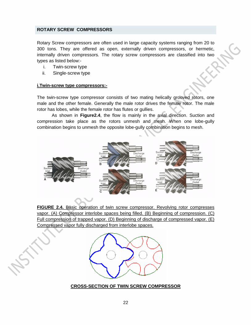
ii. Multiple vane type compressors:-
As shown in Figure 2.3, in multiple vane type compressors, the axis of rotation coincides
with the center of the roller (O), however, it is eccentric with respect to the center of the
cylinder (O’). The rotor consists of a number of slots with sliding vanes. During the
running of the compressor, the sliding vanes, which are normally made of non-metallic
materials, are held against the cylinder due to centrifugal forces. The number of
compression strokes produced in one revolution of the rotor is equal to the number of
sliding vanes, thus an 8-vane compressor produces 8 compression strokes in one
rotation.
In these compressors, sealing is required between the vanes and cylinder, between the
vanes and the slots on the rotor and between the rotor and the end plate. However,
since pressure difference across each slot is only a fraction of the total pressure
difference, the sealing is not as critical as in fixed vane type compressor.
FIGURE 2.3 SHOWS A MULTIPLE VANE TYPE COMPRESSOR
22
ROTARY SCREW COMPRESSORS
Rotary Screw compressors are often used in large capacity systems ranging from 20 to
300 tons. They are offered as open, externally driven compressors, or hermetic,
internally driven compressors. The rotary screw compressors are classified into two
types as listed below:-
i. Twin-screw type
ii. Single-screw type
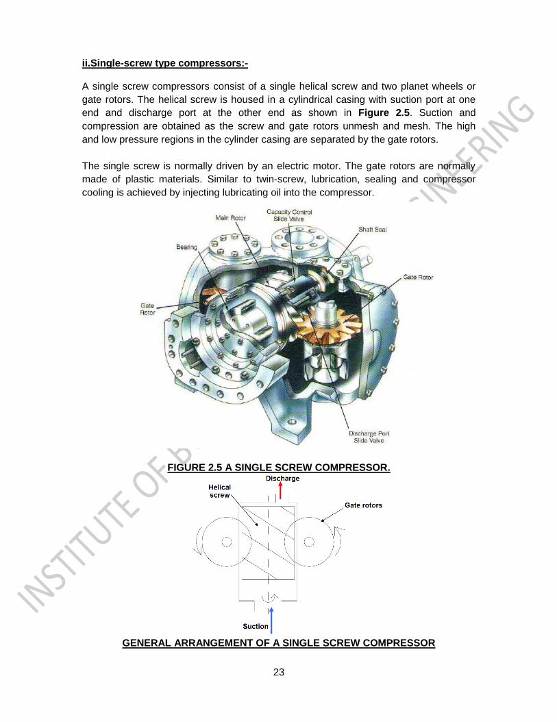
i.Twin-screw type compressors:-
The twin-screw type compressor consists of two mating helically grooved rotors, one
male and the other female. Generally the male rotor drives the female rotor. The male
rotor has lobes, while the female rotor has flutes or gullies.
As shown in Figure2.4, the flow is mainly in the axial direction. Suction and
compression take place as the rotors unmesh and mesh. When one lobe-gully
combination begins to unmesh the opposite lobe-gully combination begins to mesh.
FIGURE 2.4. Basic operation of twin screw compressor. Revolving rotor compresses
vapor. (A) Compressor interlobe spaces being filled. (B) Beginninq of compression. (C)
Full compression of trapped vapor. (D) Beginning of discharge of compressed vapor. (E)
Compressed vapor fully discharged from interlobe spaces.
CROSS-SECTION OF TWIN SCREW COMPRESSOR
23
ii.Single-screw type compressors:- A single screw compressors consist of a single helical screw and two planet wheels or
gate rotors. The helical screw is housed in a cylindrical casing with suction port at one
end and discharge port at the other end as shown in Figure 2.5. Suction and
compression are obtained as the screw and gate rotors unmesh and mesh. The high
and low pressure regions in the cylinder casing are separated by the gate rotors.
The single screw is normally driven by an electric motor. The gate rotors are normally
made of plastic materials. Similar to twin-screw, lubrication, sealing and compressor
cooling is achieved by injecting lubricating oil into the compressor.
FIGURE 2.5 A SINGLE SCREW COMPRESSOR.
GENERAL ARRANGEMENT OF A SINGLE SCREW COMPRESSOR
24
ROTARY SCROLL COMPRESSORS
The rotary scroll compressor is commonly used in residential airconditioning and heat
pump application. Benefits of the scroll includes fewer moving parts, less internal
friction, smooth compression cycle with
low torque, low noise levels, and low
vibration levels. A scroll compressor
generates a series of crescent shaped
gas pockets between two scrolls, as
shown in Figure 2.6. One scroll-the fixed
scroll-remains stationary. The other
scroll- the orbiting scroll- rotates through
the use os the swing link. As the motion
occurs, the pockets between the two
forms are slowly pushed to the center of
the two scrolls. This reduces the gas
volume. When the pocket reaches the
center of the scroll, the gas is at a high
pressure. It is discharged out of the
center port. During this compression
process, several pockets are being
formed at the same time. The suction
process from the outer portion of the scroll & the discharge from the inner portion are
continuous. This continuous process gives compressor very smooth action.
Figure 2.6. compression in the
scroll is caused by the interaction
of an orbiting scroll mated within
a stationary scroll. (1) Gas drawn
into an outer opening as one of
the scroll orbits. (2) As the
orbiting motion continues, the
open passage is sealed off & the
gas is forced to the center of the
scroll. (3) The pocket becomes
progressively small in volume.
This creates increasingly higher
gas pressures. (4) Discharge
pressure is reached at the center
of the pocket. Gas is released
from the port of the stationary scroll member. (5) In actual operation, six gas passages
are in various stages of compression at all times. This creates nearly continuous suction
& discharge.
25
CENTRIFUGAL COMPRESSORS
Centrifugal compressors also known as turbo-compressors, they belong to the roto-
dynamic type of compressors. They are designed to use with large-capacity systems
ranging in size from 50 to 5,000 Tons. In these compressors the required pressure rise
takes place due to the continuous conversion of angular momentum imparted to the
refrigerant vapour by a high-speed impeller into static pressure. Unlike reciprocating
compressors, centrifugal compressors are steady-flow devices hence they are subjected
to less vibration and noise.
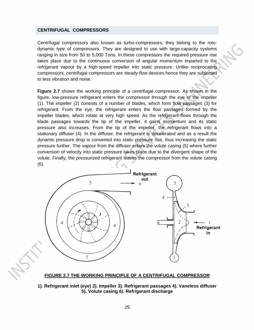
Figure 2.7 shows the working principle of a centrifugal compressor. As shown in the
figure, low-pressure refrigerant enters the compressor through the eye of the impeller
(1). The impeller (2) consists of a number of blades, which form flow passages (3) for
refrigerant. From the eye, the refrigerant enters the flow passages formed by the
impeller blades, which rotate at very high speed. As the refrigerant flows through the
blade passages towards the tip of the impeller, it gains momentum and its static
pressure also increases. From the tip of the impeller, the refrigerant flows into a
stationary diffuser (4). In the diffuser, the refrigerant is decelerated and as a result the
dynamic pressure drop is converted into static pressure rise, thus increasing the static
pressure further. The vapour from the diffuser enters the volute casing (5) where further
conversion of velocity into static pressure takes place due to the divergent shape of the
volute. Finally, the pressurized refrigerant leaves the compressor from the volute casing
(6).
FIGURE 2.7 THE WORKING PRINCIPLE OF A CENTRIFUGAL COMPRESSOR
1). Refrigerant inlet (eye) 2). Impeller 3). Refrigerant passages 4). Vaneless diffuser
5). Volute casing 6). Refrigerant discharge
26
CONDENSERS
The purpose of the condenser in a vapour compression cycle is to accept the hot, high-
pressure gas from the compressor and cool it to remove first the superheat and then the
latent heat, so that the refrigerant will condense back to a liquid. In addition, the liquid is
usually slightly subcooled. In nearly all cases, the cooling medium will be air or water.
Types of condensers:- Based on the external fluid, condensers are classified into three types as mentioned below :-
i. Air cooled condensers ii. Water cooled condensers iii. Evaporative condensers
i. Air cooled condensers:-
As the name implies, in air-cooled condensers air is the external fluid, i.e., the
refrigerant rejects heat to air flowing over the condenser.
Air-cooled condensers can be further classified into two types as listed below:-
a) Natural convection type
b) Forced convection type
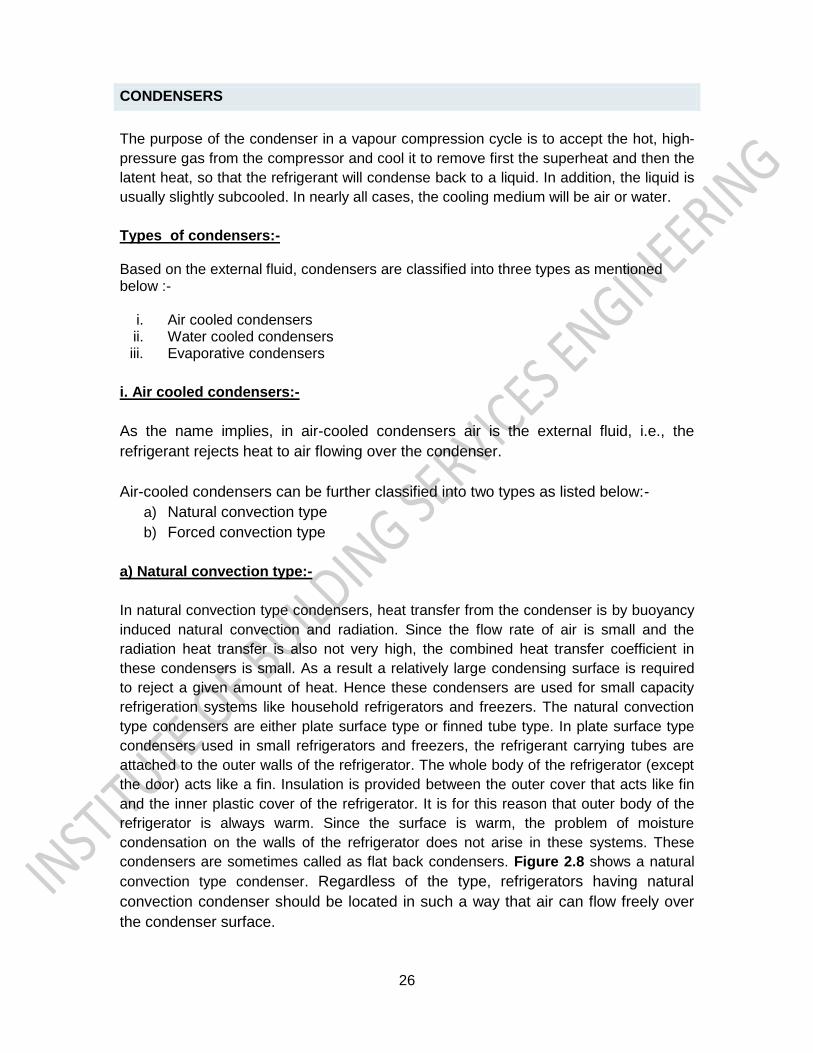
a) Natural convection type:-
In natural convection type condensers, heat transfer from the condenser is by buoyancy
induced natural convection and radiation. Since the flow rate of air is small and the
radiation heat transfer is also not very high, the combined heat transfer coefficient in
these condensers is small. As a result a relatively large condensing surface is required
to reject a given amount of heat. Hence these condensers are used for small capacity
refrigeration systems like household refrigerators and freezers. The natural convection
type condensers are either plate surface type or finned tube type. In plate surface type
condensers used in small refrigerators and freezers, the refrigerant carrying tubes are
attached to the outer walls of the refrigerator. The whole body of the refrigerator (except
the door) acts like a fin. Insulation is provided between the outer cover that acts like fin
and the inner plastic cover of the refrigerator. It is for this reason that outer body of the
refrigerator is always warm. Since the surface is warm, the problem of moisture
condensation on the walls of the refrigerator does not arise in these systems. These
condensers are sometimes called as flat back condensers. Figure 2.8 shows a natural
convection type condenser. Regardless of the type, refrigerators having natural
convection condenser should be located in such a way that air can flow freely over
the condenser surface.
27
FIGURE 2.8 NATURAL CONVECTION TYPE CONDENSER
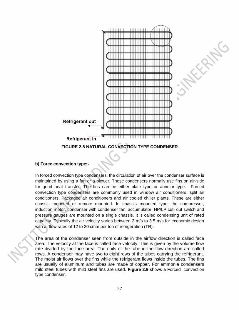
b) Force convection type:-
In forced convection type condensers, the circulation of air over the condenser surface is
maintained by using a fan or a blower. These condensers normally use fins on air-side
for good heat transfer. The fins can be either plate type or annular type. Forced
convection type condensers are commonly used in window air conditioners, split air
conditioners, Packaged air conditioners and air cooled chiller plants. These are either
chassis mounted or remote mounted. In chassis mounted type, the compressor,
induction motor, condenser with condenser fan, accumulator, HP/LP cut- out switch and
pressure gauges are mounted on a single chassis. It is called condensing unit of rated
capacity. Typically the air velocity varies between 2 m/s to 3.5 m/s for economic design
with airflow rates of 12 to 20 cmm per ton of refrigeration (TR).
The area of the condenser seen from outside in the airflow direction is called face area. The velocity at the face is called face velocity. This is given by the volume flow rate divided by the face area. The coils of the tube in the flow direction are called rows. A condenser may have two to eight rows of the tubes carrying the refrigerant. The moist air flows over the fins while the refrigerant flows inside the tubes. The fins are usually of aluminum and tubes are made of copper. For ammonia condensers mild steel tubes with mild steel fins are used. Figure 2.9 shows a Forced convection type condenser.
28
FIGURE 2.9 FORCED CONVECTION TYPE CONDENSER
ii. Water cooled condensers:-
In water cooled condensers water is the external fluid. Many large commercial
refrigerating units use a water-cooled condenser. This condenser are classified into
three types as per there construction, as listed below:-
a) Shell & tube condensers
b) Shell & coil condensers
c) Coil in coil condensers
a) Shell & tube condensers:-
This is the most common type of condenser used in systems from 2 TR upto thousands
of TR capacity. In these condensers the refrigerant flows through the shell while water
flows through the tubes in single to four passes. The condensed refrigerant collects at
the bottom of the shell. The coldest water contacts the liquid refrigerant so that some
subcooling can also be obtained. The liquid refrigerant is drained from the bottom to the
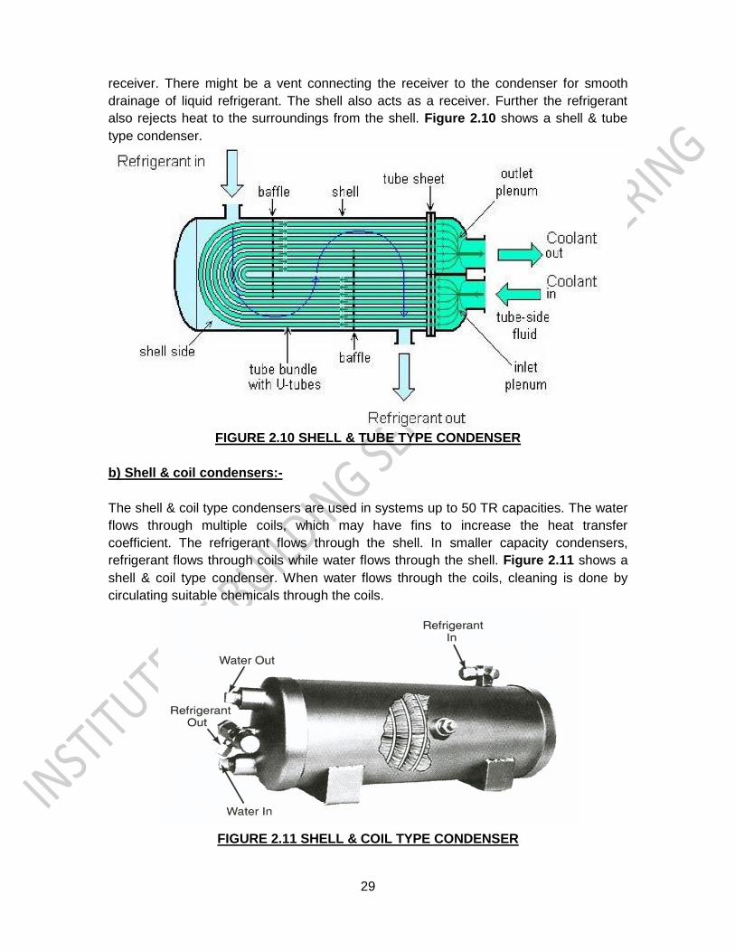
29
receiver. There might be a vent connecting the receiver to the condenser for smooth
drainage of liquid refrigerant. The shell also acts as a receiver. Further the refrigerant
also rejects heat to the surroundings from the shell. Figure 2.10 shows a shell & tube
type condenser.
FIGURE 2.10 SHELL & TUBE TYPE CONDENSER
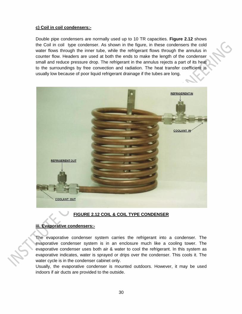
b) Shell & coil condensers:-
The shell & coil type condensers are used in systems up to 50 TR capacities. The water
flows through multiple coils, which may have fins to increase the heat transfer
coefficient. The refrigerant flows through the shell. In smaller capacity condensers,
refrigerant flows through coils while water flows through the shell. Figure 2.11 shows a
shell & coil type condenser. When water flows through the coils, cleaning is done by
circulating suitable chemicals through the coils.
FIGURE 2.11 SHELL & COIL TYPE CONDENSER
30
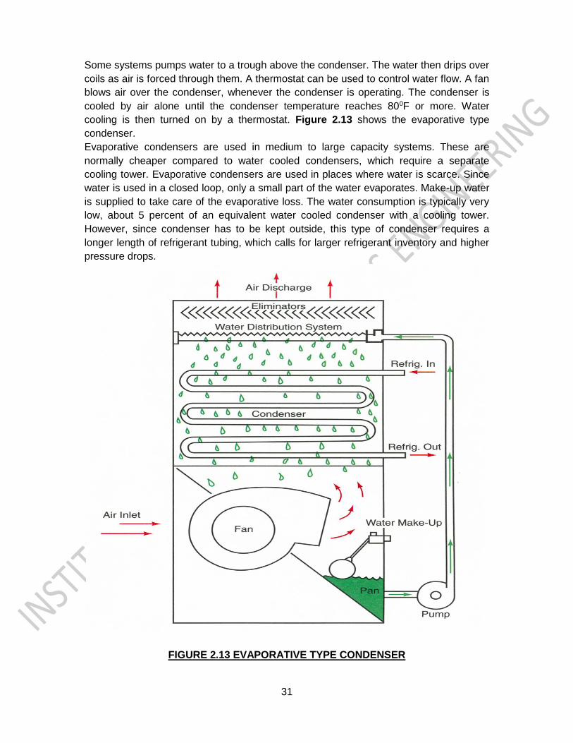
c) Coil in coil condensers:-
Double pipe condensers are normally used up to 10 TR capacities. Figure 2.12 shows
the Coil in coil type condenser. As shown in the figure, in these condensers the cold
water flows through the inner tube, while the refrigerant flows through the annulus in
counter flow. Headers are used at both the ends to make the length of the condenser
small and reduce pressure drop. The refrigerant in the annulus rejects a part of its heat
to the surroundings by free convection and radiation. The heat transfer coefficient is
usually low because of poor liquid refrigerant drainage if the tubes are long.
FIGURE 2.12 COIL & COIL TYPE CONDENSER
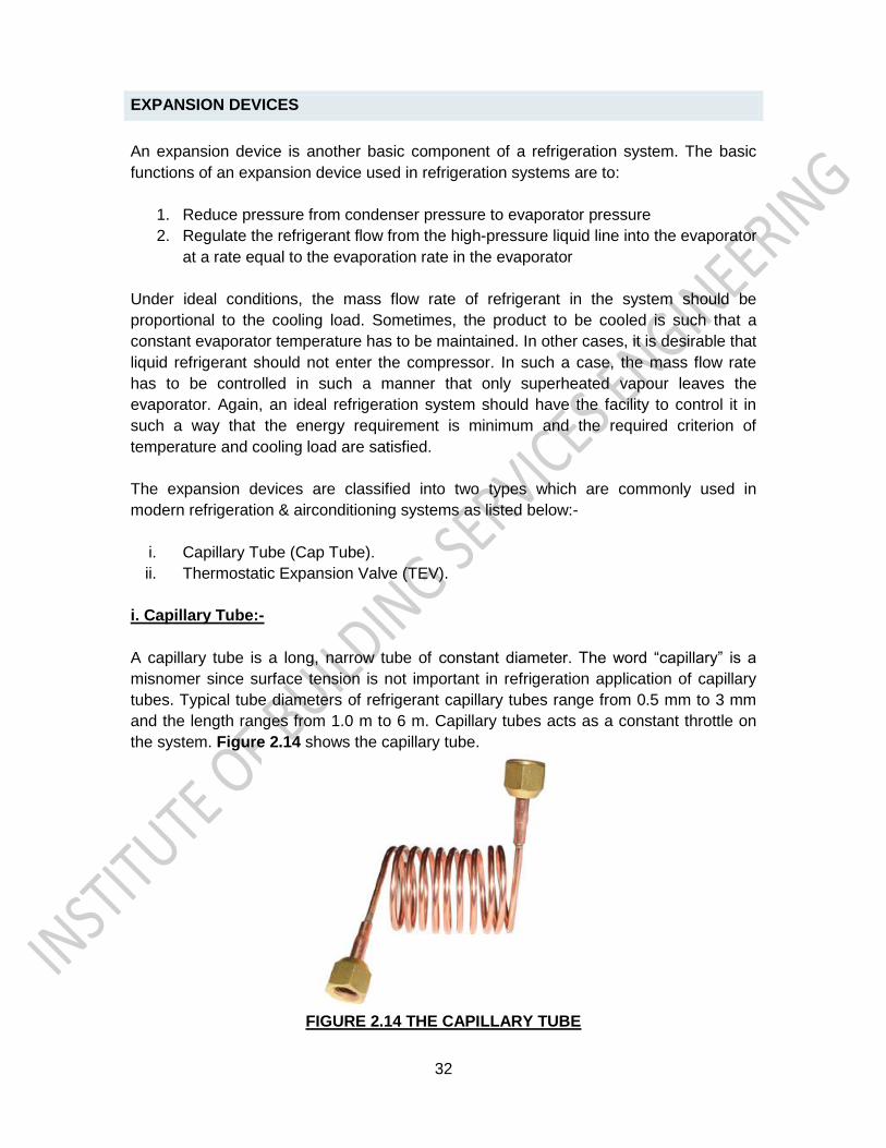
iii. Evaporative condensers:-
The evaporative condenser system carries the refrigerant into a condenser. The
evaporative condenser system is in an enclosure much like a cooling tower. The
evaporative condenser uses both air & water to cool the refrigerant. In this system as
evaporative indicates, water is sprayed or drips over the condenser. This cools it. The
water cycle is in the condenser cabinet only.
Usually, the evaporative condenser is mounted outdoors. However, it may be used
indoors if air ducts are provided to the outside.
31
Some systems pumps water to a trough above the condenser. The water then drips over
coils as air is forced through them. A thermostat can be used to control water flow. A fan
blows air over the condenser, whenever the condenser is operating. The condenser is
cooled by air alone until the condenser temperature reaches 800F or more. Water
cooling is then turned on by a thermostat. Figure 2.13 shows the evaporative type
condenser.
Evaporative condensers are used in medium to large capacity systems. These are
normally cheaper compared to water cooled condensers, which require a separate
cooling tower. Evaporative condensers are used in places where water is scarce. Since
water is used in a closed loop, only a small part of the water evaporates. Make-up water
is supplied to take care of the evaporative loss. The water consumption is typically very
low, about 5 percent of an equivalent water cooled condenser with a cooling tower.
However, since condenser has to be kept outside, this type of condenser requires a
longer length of refrigerant tubing, which calls for larger refrigerant inventory and higher
pressure drops.
FIGURE 2.13 EVAPORATIVE TYPE CONDENSER
32
EXPANSION DEVICES
An expansion device is another basic component of a refrigeration system. The basic
functions of an expansion device used in refrigeration systems are to:
1. Reduce pressure from condenser pressure to evaporator pressure
2. Regulate the refrigerant flow from the high-pressure liquid line into the evaporator
at a rate equal to the evaporation rate in the evaporator
Under ideal conditions, the mass flow rate of refrigerant in the system should be
proportional to the cooling load. Sometimes, the product to be cooled is such that a
constant evaporator temperature has to be maintained. In other cases, it is desirable that
liquid refrigerant should not enter the compressor. In such a case, the mass flow rate
has to be controlled in such a manner that only superheated vapour leaves the
evaporator. Again, an ideal refrigeration system should have the facility to control it in
such a way that the energy requirement is minimum and the required criterion of
temperature and cooling load are satisfied.
The expansion devices are classified into two types which are commonly used in
modern refrigeration & airconditioning systems as listed below:-
i. Capillary Tube (Cap Tube).
ii. Thermostatic Expansion Valve (TEV).
i. Capillary Tube:-
A capillary tube is a long, narrow tube of constant diameter. The word “capillary” is a
misnomer since surface tension is not important in refrigeration application of capillary
tubes. Typical tube diameters of refrigerant capillary tubes range from 0.5 mm to 3 mm
and the length ranges from 1.0 m to 6 m. Capillary tubes acts as a constant throttle on
the system. Figure 2.14 shows the capillary tube.
FIGURE 2.14 THE CAPILLARY TUBE
33
Advantages and disadvantages of capillary tubes:- a.Some of the advantages of a capillary tube are:-
1. It is inexpensive. 2. It does not have any moving parts hence it does not require maintenance 3. Capillary tube provides an open connection between condenser and the
evaporator hence during off-cycle, pressure equalization occurs between condenser and evaporator.
4. Ideal for hermetic compressor based systems, which are critically charged and factory assembled.
b.Some of the disadvantages of the capillary tube are:-
1. It cannot adjust itself to changing flow conditions in response to daily and seasonal variation in ambient temperature and load. Hence, COP is usually low under off design conditions.
2. It is susceptible to clogging because of narrow bore of the tube, hence, utmost care is required at the time of assembly. A filter-drier should be used ahead of the capillary to prevent entry of moisture or any solid particles
3. During off-cycle liquid refrigerant flows to evaporator because of pressure
difference between condenser and evaporator. The evaporator may get flooded
and the liquid refrigerant may flow to compressor and damage it when it starts.
Therefore critical charge is used in capillary tube based systems. Further, it is
used only with hermetically sealed compressors where refrigerant does not leak
so that critical charge can be used. Normally an accumulator is provided after the
evaporator to prevent slugging of compressor.
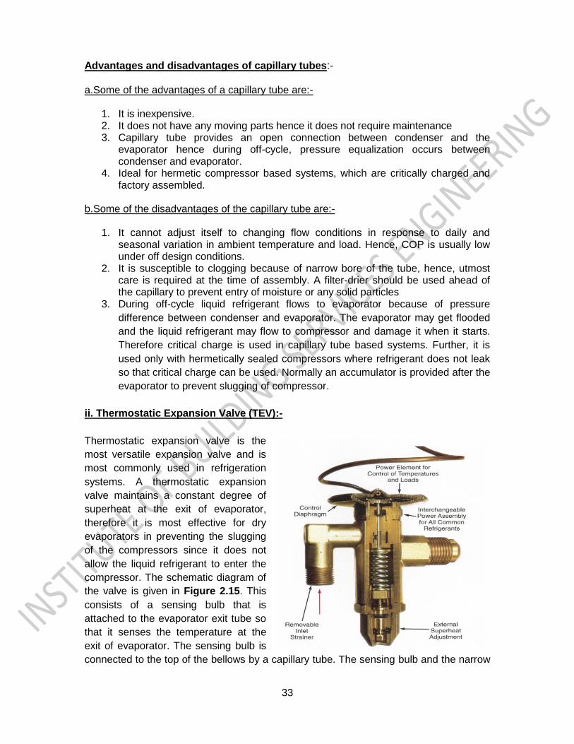
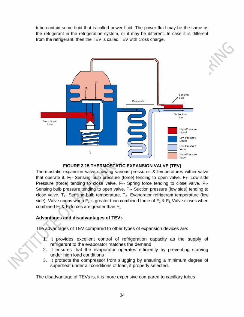
ii. Thermostatic Expansion Valve (TEV):-
Thermostatic expansion valve is the
most versatile expansion valve and is
most commonly used in refrigeration
systems. A thermostatic expansion
valve maintains a constant degree of
superheat at the exit of evaporator,
therefore it is most effective for dry
evaporators in preventing the slugging
of the compressors since it does not
allow the liquid refrigerant to enter the
compressor. The schematic diagram of
the valve is given in Figure 2.15. This
consists of a sensing bulb that is
attached to the evaporator exit tube so
that it senses the temperature at the
exit of evaporator. The sensing bulb is
connected to the top of the bellows by a capillary tube. The sensing bulb and the narrow
34
tube contain some fluid that is called power fluid. The power fluid may be the same as
the refrigerant in the refrigeration system, or it may be different. In case it is different
from the refrigerant, then the TEV is called TEV with cross charge.
FIGURE 2.15 THERMOSTATIC EXPANSION VALVE (TEV)
Thermostatic expansion valve showing various pressures & temperatures within valve
that operate it. F1- Sensing bulb pressure (force) tending to open valve. F2- Low side
Pressure (force) tending to close valve. F3- Spring force tending to close valve. P1-
Sensing bulb pressure tending to open valve. P2- Suction pressure (low side) tending to
close valve. T1- Sensing bulb temperature. T2- Evaporator refrigerant temperature (low
side). Valve opens when F1 is greater than combined force of F2 & F3. Valve closes when
combined F2 & F3 forces are greater than F1.
Advantages and disadvantages of TEV:- The advantages of TEV compared to other types of expansion devices are:
1. It provides excellent control of refrigeration capacity as the supply of
refrigerant to the evaporator matches the demand 2. It ensures that the evaporator operates efficiently by preventing starving
under high load conditions 3. It protects the compressor from slugging by ensuring a minimum degree of
superheat under all conditions of load, if properly selected.
The disadvantage of TEVs is, it is more expensive compared to capillary tubes.
35
EVAPORATORS
An evaporator, like condenser which also acts as a heat exchanger. The purpose of the
evaporator is to receive low-pressure, low-temperature fluid from the expansion valve
and to bring it in close thermal contact with the load. The refrigerant takes up its latent
heat from the load and leaves the evaporator as a dry gas. The name evaporator refers
to the evaporation process occurring in the heat exchanger. The evaporators are
generally called as cooling coils
The evaporators are classified in several types, but only two types of evaporators are
majorly used in air-conditioning field, as listed below:-
1. The evaporators used for cooling air, by blowing air upon the cooling coil or
evaporator to keep the space conditioned. These are also called direct
expansion system.
2. The evaporators those are submerged in a liquid or liquid passed over the
cooling coil, such as water or brine solutions. These systems are also called
chilled water system.
1.Direct Expansion system (DX System):-
In direct expansion systems, air is expanded direct when it gets contact with the cooling
coil or air blown over the cooling coil by a means of fan or blower. Hence the space get
conditioned. These evaporators or cooling are used for cooling and dehumidifying the air
directly by the refrigerant flowing in the tubes. Similar to fin-and-tube type condensers,
these evaporator consists of coils placed in a number of rows with fins mounted on it to
increase the heat transfer area. In general terms air gets direct contact with the
evaporator & gets expanded.
2.Chilled water system:-
In chilled water system, a secondary refrigerant i.e. water or a brine solution is passed
over the evaporator or cooling coil just like shell and tube condenser used in water
cooled condensers, where the water gets chilled due to heat transfer & the chilled water
is circulated through chilled water pipes to the air handling unit or a fan coil unit. Through
the cooling coil of the air handling unit or a fan coil unit the space get conditioned. In
general terms cooling is achieved by a heat transfer, where water gets chilled in
evaporator & then circulated through cooling coils of air handling units or fan coil unit.