what is raster blending - alaska dggsdggs.alaska.gov/webpubs/dggs/po/text/po2014_009.pdf · global...
TRANSCRIPT

Page 1 of 21
Abstract: The Division of Geological & Geophysical Surveys (DGGS) uses Global Mapper software to create slope-enhanced shaded relief images and raster blended geotiffs for use in ArcMap as basemaps for geologic maps. Global Mapper is a GIS data processing application created by Blue Marble Geographics that offers a wide variety of built in functionality, including raster blending and other advanced capabilities. Slope enhanced shaded relief images are superior to standard hillshades and are easy to create in Global Mapper. Raster blending combines geologic unit polygons, shaded relief images, and topographic base maps. The resulting geotiff is a balanced image that compliments, rather than dominates a map. Geotiffs created in Global Mapper are easily brought into an ArcMap document and enhance the overall look and feel of a map. This presentation will detail how to create a slope enhanced shaded relief image, raster blended geotiff, and the process of integrating it all into a final cartographic product. What is Raster Blending: Blending one raster into another so the properties of both are preserved. Why Raster Blending:
1. To avoid using transparency on geologic maps. 2. To balance the shading and topographic base map so they complement, rather than
dominate, the geologic mapping 3. Transparency (the only blending option that ArcGIS provides), generally produces a
much less visually appealing image than raster blending.
Page 2 of 21
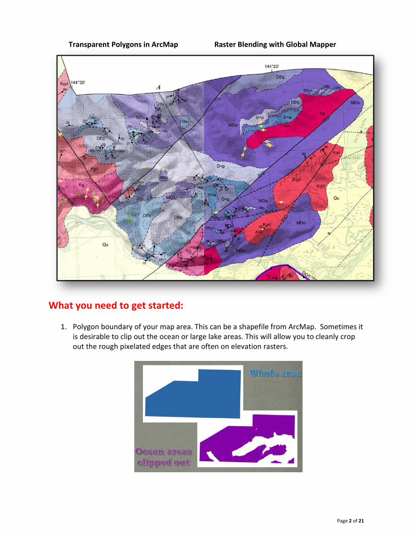
Transparent Polygons in ArcMap Raster Blending with Global Mapper
What you need to get started:
1. Polygon boundary of your map area. This can be a shapefile from ArcMap. Sometimes it is desirable to clip out the ocean or large lake areas. This will allow you to cleanly crop out the rough pixelated edges that are often on elevation rasters.

Page 3 of 21
2. Elevation data for your project. See Step 2 for more information.
3. Digital Raster Graphics (DRGs) that cover your map area. See Step 3 for more information.
4. Global Mapper Software. Global Mapper is a data processing application that offers a wide variety of built in functionality. It is available for download online. A single License costs about $450. License upgrades (for example – from version 14 to version 15) costs about $170. http://www.bluemarblegeo.com/products/global-mapper-purchase.php

Page 4 of 21
Step 1 — Export Geology Polygons from ArcMap
The first step to creating a raster blended base map is to export a high resolution raster made from your map unit polygons and patterns. Open your project in an ArcMap document.
1) Symbolize the map unit polygons with the desired colors. Convert Symbology to Representations. The representation layer will be added to the table of contents. Feature class representations let you store symbology with your features in the geodatabase.
2) Symbolize polygons containing patterns. Patterns need to be stored as representations so
that they will scale properly at all zoom levels in data view. NOTE: Including patterns in the raster blended base map is optional. Generally, if you want a pattern to be prominent and lay “on top” of the base map, do NOT export them with your geologic polygons. If you want your patterns to be blended with the other elements and be more subdued, export them with the geologic polygons. For more information about patterns as cartographic representations, please check out: Gallagher, P.E., 2013, Creating FGDC-compliant cartographic representations (poster): ESRI International Users Conference, San Diego, California, July 7-12, 2013: Alaska Division of Geological & Geophysical Surveys, 15 p., 1 sheet. http://www.dggs.alaska.gov/pubs/id/25339

Page 5 of 21
3) IN DATA VIEW (not layout view) turn off all layers except for the geology polygons (and
optional pattern polygons). Make sure layer transparency is set to 0 (not transparent).
4) Set the data frame reference scale. This will ensure that the patterns (as representations) will be at the correct scale for your map.
5) Zoom to the full extent of the polygons and Export Map.

Page 6 of 21
6) Set the Export specifications. a) Save as type TIFF at 2400 dpi resolution b) On the General tab
i) Check the Write World File box. Writing a world file allows georeferencing information to be stored in a separate world file.
c) On the Format tab i) Choose 24-bit True Color, No Compression, and check the Write GeoTIFF Tags box.
Writing GeoTIFF tags allows georeferencing information to be stored internally in the tiff.
7) Click Save. Save as geo_polys.tif

Page 7 of 21
Step 2 — Get Best Available Elevation Data
What elevation data you use depends greatly on your project, the size of area you are mapping, and what elevation data is available. You can use almost any kind of elevation data, including LiDAR data, in Global Mapper. Here at the DGGS, most of our maps are at 1:63,360 scale and cover a large area. For raster blending, it is best to have elevation data of the same scale cover your entire map area. The USGS National Map Viewer offers a convenient way to look up what is the best available National Elevation Dataset. http://earthexplorer.usgs.gov/
1) View what elevation data is available. Use the Download by Bounding Box tool on the Standard tool tab to define the approximate extent of your map area. Then, check the Elevation Availability box in the left-side Overlay table of contents. In our Whittier example, you can see that 3 meter data is not available in our area, but 10 meter data is.

Page 8 of 21
2) Begin the download process. Click on the box that you drew earlier and select Download.
3) Choose what type of data to download. Check the Elevation box and click next.

Page 9 of 21
4) Choose the product to download. Clicking the name of the product will color the area on the background screen and can be used to make sure you are downloading the correct piece. Choose the IMG format and click Next.
5) Download the data. Once you click Next, the Cart tab will be shown in the viewer. Verify you have chosen the correct data and click Checkout. Enter and verify your email address. Click Place Order. An email with a download link will be sent to you shortly. Download and unzip the elevation data to your working project folder.
Step 3 — Get Most Recent Topo DRG
What you use for a base map also depends greatly on the specifications of your project. You do not necessarily have to use the topo DRGs for your base map information. For example, you could generate contours from imagery and use those instead. Here at the DGGS, we use the USGS Digital Raster Graphics. A Digital Raster Graphic (DRG) is a scanned image of a USGS standard series topographic map, including all of the collar information. The images are georeferenced to the surface of the earth and fit to the Universal Transverse Mercator (UTM) projection. Most of these maps were made in the 50’s, but some have had minor updates since then. The USGS Earth Explorer offers a convenient way to look up and download the most recent DRGs. It functions similar to the National Map Viewer. http://earthexplorer.usgs.gov/ Before you begin, it is VERY helpful to know what 63,360 map sheets you are looking for. In our Whittier example, we will need the Seward D-4 and D-5 sheets.

Page 10 of 21
1) Define area of interest. In the Search Criteria tab, place coordinates on the map to define your area of interest. In the Data Sets tab, expand the Digital Maps option and check the DRG box.
2) Choose the data sets. On the Results tab, find the 15-minute DRGs that cover your area.
Click the Add to Bulk Download button . Note – you will need to install the Bulk Download Application before you can download the data.
http://earthexplorer.usgs.gov/bulk/help

Page 11 of 21
3) View Item Basket. Once all the required DRGs are added, click the View Item Basket button. Proceed to the checkout and submit the order. An email will be sent to you when the order is ready.
4) Open the Bulk Download Application.
5) Accept warning. Click OK when an Insufficient Privileges error pops up.

Page 12 of 21
6) Enter login credentials.
7) Select your order.
8) Choose a destination folder.

Page 13 of 21
9) Download the data.
Step 4 — Create Seamless DRG 1) Open the DRGs in Global Mapper. Use the 64-bit program. There is no need to unzip the
files first – Global Mapper unzips them automatically! You can also open both files at once by selecting them both and clicking Open.
Page 14 of 21
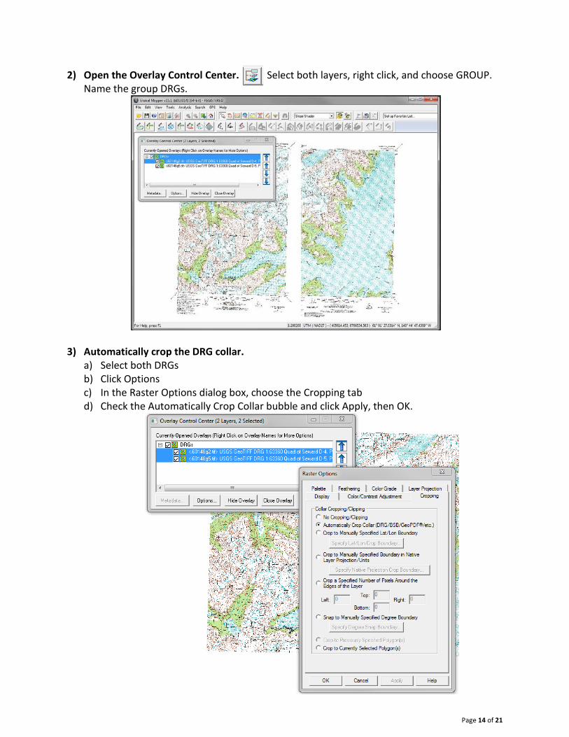
2) Open the Overlay Control Center. Select both layers, right click, and choose GROUP.
Name the group DRGs.
3) Automatically crop the DRG collar.
a) Select both DRGs b) Click Options c) In the Raster Options dialog box, choose the Cropping tab d) Check the Automatically Crop Collar bubble and click Apply, then OK.
Page 15 of 21
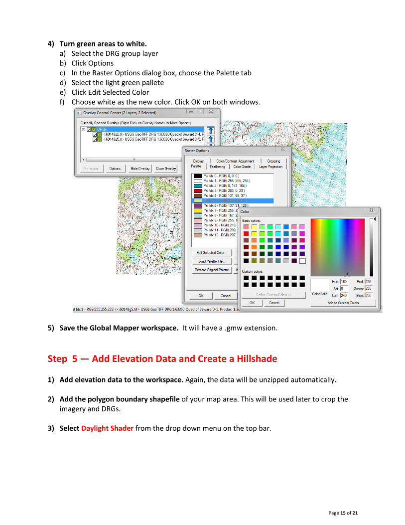
4) Turn green areas to white. a) Select the DRG group layer b) Click Options c) In the Raster Options dialog box, choose the Palette tab d) Select the light green pallete e) Click Edit Selected Color f) Choose white as the new color. Click OK on both windows.
5) Save the Global Mapper workspace. It will have a .gmw extension. Step 5 — Add Elevation Data and Create a Hillshade 1) Add elevation data to the workspace. Again, the data will be unzipped automatically.
2) Add the polygon boundary shapefile of your map area. This will be used later to crop the
imagery and DRGs.
3) Select Daylight Shader from the drop down menu on the top bar.

Page 16 of 21
4) Set the Daylight Shader Configuration options. a) Click the Configuration button b) On the Vertical Options Tab:
i) Select Daylight Shader from the dropdown menu ii) Check Enable Hill Shading box iii) Choose Native Overlay Units bubble iv) Under light Direction, set: Altitude = 60, Azimuth = 340 v) Hill Shade Shadow Darkness = 36 vi) Hill Shade highlight = 0
c) On the Shader Options Tab: i) Set Surface Color of Daylight Shader to white ii) Under Slope Shader
(a) For Minimum Slope, set: Slope Value = 0 degrees, Color = white (b) For Maximum Slope, set: Slope Value =5 degrees, Color = Black
d) Click OK for the configuration Window
5) Select border outline polygon. Make sure it is “on top” of the elevation layer – in Global Mapper, that will be at the BOTTOM of the list. Once selected, turn the outline layer off, but leave it selected.

Page 17 of 21
6) Export the map area hillshade. a) click File Export b) Export Raster/Image Format c) Select GeoTiff and click OK d) On the GeoTiff Export Options tab
i) select 24-bit RGB bubble ii) Pattete = Image Optimized iii) Compression = JPEG Compression
Click OK to warning that pops up iv) ADVANCED: JPEG-in-TIFF Quality = 90
e) On the Export Bounds tab i) Select Crop to Selected Area Feature box
7) Save as hillshade.tiff

Page 18 of 21
Step 6 — Create Slopeshade 1) Select Slope Shader from the drop down menu on the top bar.
2) Keep all settings the same as in 5.4 above.
3) Select border polygon as in 5.5 above. 4) Export the map area slopeshade as in 5.6 above. 5) Save as slopeshade.tiff Step 7 — Create Slope-enhanced hillshade 1) In the Overlay Control Center, unselect all overlays.
2) Add the hillshade and slopeshade geotiffs you made in steps 5 and 6.
a) Make sure the hillshade is BELOW the slopeshade in the overlay list b) Select hillshade.tif
i) With hillshade.tif selected, click the Options. This brings up the Raster Options dialog box.
ii) Blend Mode = Screen
3) Select border polygon as in 5.5 and 6.3 above. 4) Export the map area slopeshade as in 5.6 and 6.4 above.
5) Save as slopehillshade.tiff

Page 19 of 21
Step 8 — Create Final Tiff that includes DRGs, slope enhanced hillshade, and geology polygons 1) Add the geo_polys.tif you made in step 1. 2) Arrange the Overlay List in the following order:
Top: DRGs Top Middle: Slopehillshade from step 7 above Bottom Middle: Geologic polygons from step 1 above Bottom: Border polygon shapefile
3) Set Raster Options of geologic polygons i) Select geo_polys.tiff ii) Click Options
(1) Blend Mode = Multiply (2) Translucency = 100 (completely opaque)

Page 20 of 21
4) Set Raster Options of slope-enhanced hillshade a) Select slopehillshade.tiff
i) Click Options (1) Blend Mode = Multiply (2) Translucency = 45 (just get close using the slider – exact number isn’t necessary)
5) Set Raster Options DRGs a) Select DRG group layer
i) Click Options (1) Blend Mode = No Blend (2) Translucency = 30 (just get close using slider – exact number not necessary)

Page 21 of 21
6) Export the map area slopeshade as in 5.6 and 6.4 above. 7) Save as final.tiff Step 9 — Display final geotiff in ArcMap 1) Add final.tif into ArcMap.
a) Click “yes” when asked to build pyramids
WARNING – the geotiff will look HORRIBLE at this point. Don’t worry – we are about to fix it!
2) Correct the symbology a) Right click the layer b) Open Properties
i) On the Symbology Tab (a) Select None from the Stretch Type pull-down list (b) Uncheck the Apply Gamma Stretch box
ii) Click OK 3) Turn on any additional layers, such as contacts, faults, stations, structure symbols, etc.
YOU DID IT! You are done! Enjoy your new balanced and visually pleasing base map