what is the centaur mission? - grc.nasa.gov · liquid hydrogen is superior to previous or...
TRANSCRIPT

• •
C E N TAU R
I
* What is Centaur?
The Centaur is a two stage missile. The first stage is an Atlas Inter Continental Ballistic Missile with three engines (two booster and one sustainer) producing a total of approximately 360,000 pounds of thrust. The Atlas engines use Liquid Oxygen and Kerosene as fuel. The second stage is a Centaur Tank with two engines producing a total of approximately 30,000 pounds of thrust. The Centaur engines use Liquid Oxygen and Liquid Hydrogen as fuel, and when fully developed, will have the capability of engine shutdown and restart in space. Prime Contractors for the Centaur Vehicle are: Atlas Booster and Centaur Tank - General Dynamics/Astronautics; Centaur Engines - Pratt & Whitney Aircraft; Guidance System - Minneapolis Honeywell.
* How did Centaur originate?
The Centaur Project originated in 1958 with the Advanced Research Projects Agency (ARPA). Technical control was assigned to the Air Force Research and Development Command (ARDC) with an authorization to develop and flight test a total of six Atlas/Centaur launch vehicles. As a result, in the fall of 1958, ARDC contracted with Pratt & Whitney Division of United Aircraft Corporation for the development of a high impulse, liquid hydrogen/ liquid oxygen engine to be used in the Centaur stage. General Dynamics/ Astronautics (then Convair Astronautics) was assigned the task to make modifications on the Atlas first stage booster, and design and develop the second stage Centaur. The Pratt & Whitney engines, for the second stage, are supplied to General Dynamics as Government Furnished Equipment.
On July 1, 1959, the responsibility for development of the Centaur was transferred from ARPA to NASA, and on July 1, 1960, the project was assigned to Marshall Space Flight Center. Shortly thereafter, on July 8, 1960, an additional four vehicles were added to the Project.
After the first launch on May 8, 1962, an extensive evaluation was made of the entire program by both NASA and the various contractors. Subsequent to this review, the management of the Centaur Project was transferred to Lewis Research Center on October 8, 1962.
Since the transfer of project managership, a basic reformation and consolidation of vehicle development and contracts has been accomplished. The program has been reduced to eight R&D vehicles including the first flight in 1962. A separate contract has been set up for engineering analysis and study problems related to the needs of the development program.
1

I
* What is the Centaur Mission?
The prime mission for Centaur at this time is Surveyor Lander, a Spacecraft design~d for a soft lunar landing and subsequent transmission of data from the moon's surface and sub-surface. Surveyor Lander is an instrumentpacked vehicle designed to take pictures of the moon's surface, sample soil, test for moon quakes, measure gravity and gather data on radiation, atmosphere and magnetism. The Surveyor program directly supports NASA's Manned Lunar Landing Program.
Planetary flights to Venus and Mars are also planned to utilize Centaur launch vehicles and Mariner "B" Spacecraft. These flights will carry ultra violet spectrometers, radiometers, radiation counters, plasma detectors, micrometeorite impact counters and other experiments. Mariner "B" is an essential part of our Lunar and Planetary exploration program.
Centaur is the United States' first sizeable true space vehicle. It is termed a "true space vehicle" because its engines can be started, shutdown and restarted to accomplish changes of direction and velocity in space. Centaur also is the first U. S. vehicle using liquid hydrogen as a fuel. Liquid hydrogen is superior to previous or conventional rocket propellants because of its high energy yield compared to fuel weight.
To support these and other important unmanned spacecraft flights, it is necessary to complete the principle development of the Centaur second stage vehicle by late 1964. Further development will continue to achieve reliable coast phase flight and gain increased performance margins.
2

__
- 8 -
Payload
Jettisonable nose fairing
~ ~~~Jettisonablepanel
CENTAUR stage
~1nterstage adapter
ATLAS stage
Exhibit 111-1. - ATLAS/CENTAUR vehicle arrangement.

- 9 -
ELECTRONIC
PACKAGES
H I AZUSA
"<Ii ANTENNA (j) o C\J
I r£l
L0 TANK2
1~~2:~~--& GUIDANCE
---FUEL TANK
SUSTAIN ER _1--f=¥.---1
L02 TANK
Exhibit 111-2. - Over-all view of ATLAS/CENTAUR.

II
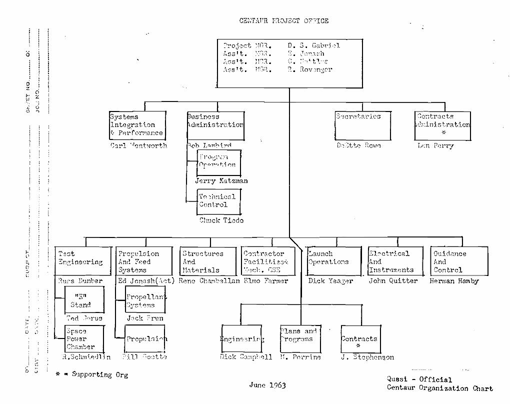
* What is the Centaur Project Office, how is it divided, and what are its prime responsibilities?
Heading the Centaur Project Office is Mr. Dave Gabriel, Project Manager. Under Mr. Gabriel there are three assistant managers: Mr. Cary Nettles, Mr. Ed Jonash and Mr. Ron Rovenger. Mr. Rovenger heads the Field Office at GD/A in San Diego.
The Business Administration Branch is headed by Mr. Robert Lambird.
The Busin~ss Administration Branch is assigned the responsibility for such program management functions as:
Developing and maintaining master schedules Formulating financial operating plans and Program Development Plans Preparation and control of quasi-contractual and financial actions
The Business Administration Branch is interested in all In House and Contractor operations which affect costs and schedules. This, of course, becomes quite inclusive. This office must monitor Contractor schedules and reports to determine their effects on costs and schedules. On a large project such as Centaur, this can indeed be a difficult assignment, and for this reason, we employ PERT and Companion Cost. Properly implemented, maintained and monitored, such techniques are invaluable.
On the financial side, we maintain our own budgeting and accounting system. First, adequate funds must be provided to do the job, and then these funds must be accounted for. The office must keep current on the funds committed and obligated to date, and what funds are available at any given point in time. Particularly, near the end of the fiscal year, this is of prime importance.
Instrumentation and Electrical Branch
The Instrumentation and Electrical Systems Branch is headed by Mr. John Quitter. This branch has the responsibility for surveying and monitoring all on-board electrical and electronic systems and subsystems with one exception, the guidance and control functions.
Some of the items under their jurisdiction are: instrumentation and telemetry systems, navigation and tracking systems, radar and azusa beacons, range safety system and electrical power storage, conversion and distribution systems. The electrical portion of ground support equipment is also monitored by this branch.
In order to properly discharge their responsibilities, the branch must review, study, evaluate and make recommendations regarding reports, proposa~
1

II
specifications, tests and test plans, and contracts which involve those subjects mentioned.
The branch, of course, must keep current with the state of the ART. Management is kept apprised of those advances which embody sound engineering design principles, and recommendations are made.
Structures and Materials Branch
Mr. Rene Chambellan is the acting chief of the Structures ana Mate~ials Branch.
The responsibilities of this branch are as follows:
Establish the structural design criteria for static, vibration shock and other dynamic load environments.
Insure that design and hardware meet the requirements for physical strength and insure that designs can be readily fabricated and reproduced.
The branch must keep informed in regards to materials available and fabrication techniques.
The branch reviews and evaluates all materials specifications, process specifications, and inspection and repair procedures. They review all stress, structural design and structural dynamics calculations and reports.
The branch reviews the results of material tests and evaluates them as they may apply to Centaur. They also analyze structural and mechanical failures during development and testing. Manufacturing defects are analyzed to determine if repair is possible or if an engineering investigation is required.
Finally, this branch also acts as a consultant in such areas as ground support equipment, test stands, etc.
Test Engineering Branch
This branch, headed by Mr. Russ Dunbar, is divided into two sections, the AWT (Altitude Wind Tunnel) Section and "E" Stand Section headed by Mr. Schmiedlin and Mr. Gerus respectively. These two sections are responsible for the LeRC tests of the Atlas/Centaur.
The AWT Section is responsible for carrying out the space environmental testing of the Centaur Vehicle and vehicle systems. Of particular interest are
2

II
propellant dynamics and thermodynamics and zero gravity problems. Test programs to study these s~bjects are developed by this section, and tests are run and results analyzed. The findings are then used by Centaur in future planning.
At the Plumbrook "E" Stand, the Atlas/Centaur is tested to determine dynamic and vibrational characteristics.
Between these two sections is divided the responsibility of learning all about Atlas/Centaur that can possibly be learned on the ground. This is in support of the basic philosophy that we will not test in space anything which can be tested on the ground.
Guidance and Control Branch
Mr. Herman Hamby heads the Guidance and Control Branch. This branch is responsible for the adequacy of the guidance system design relative to the requirements of the flight mission profiles. To properly execute this responsibility, they must establish guidance theories for assigned projects, including guidance equations and selection of parameters with regard to guidance terms used. They must conduct basic studies in the field of guidance, survey new developments, proposals and theories and analyze error sources of existing system to establish new guidance schemes and improve existing ones.
This branch must maintain an awareness of current hardware systems, schemes, philosophies, etc. They must establish trajectories for all test firings of flight vehicles, with or without guidance. They furnish preliminary and final trajectories for all test firings of flight vehicles, with or without guidance. They furnish preliminary and final trajectory data and flight mechanical and aerodynamic characteristics required for flight trajectories.
Contractor Facilities and Mechanical GSE Branch
Mr. Elmo Farmer heads the Contractor Facilities and Mechanical GSE Branch. This branch is responsible for the construction and modification of all facilities for the Centaur Program, except those located at LeRC.
Under this heading come the modifications to the launch facilities at the Atlantic Missile Range. There is also a new launch facility planned and under their jurisdiction. They are responsible for the many modifications to the various test facilities throughout the country.
Mr. Farmer's group is not only responsible for what is commonly referred to as the"brick and mortar"but will also monitor the Ground Support Equipment required for the Centaur Program. Included here are the propellant loading and handling systems at various test sites and at Atlantic Missile Range. Last, but not least, are the gas systems required for pressurizing and purging.
3

II
Launch Operations Branch
The Launch Operations Branch is headed by Mr. Dick Yeager. Dick is the coordinator and liaison for LeRC for each vehicle launch. His branch is responsible for monitoring vehicle factory checkout and acceptance tests. After the vehicle sell off, they participate in the preparation of the vehicle pre-launch checkout and test at Atlantic Missile Range.
They initiate Ground Support Equipment design changes precipitated by vehicle design changes.
They prepare the official range documentation such as program requirements, program support plan, individual flight operations requirements, initiate and coordinate data acquisition and reduction requirements~ initiate the flight data analysis for each launch and prepare reports thereof.
Propulsion and Feed Systems Branch
Ed J'onash, an Assistant Manager, is acting head of the Propulsion and Feed Systems Branch. This branch is divided into two section, the Propellant Section headed by Dr. Brun, and the Propulsion System Section headed by Bill Goette.
As the titles imply, the Propellant Section is responsible for the Propellant System. This includes the study of such areas as propellant dynamics, propellant thermodynamics, heat transfer problems on all vehicle systems, and zero gravity tests. As you are aware, Centaur uses liquid oxygen and hydrogen propellants. The temperature at which these fuels exist as a liquid are extremely low, and the field of cryogenics is fairly new. It is Dr. Brun's section that studies the handling of these propellants and the problems inherent with their handling.
The Propulsion Section evaluates changes proposed to the Pratt & Whitney A-3 engines to assure engine vehicle compatibility. They monitor production engine performance, reliability and delivery schedules and propose, monitor and evaluate advanced development programs and testing of the engines.
Systems Integration and Performance Branch
Mr. Carl Wentworth heads the Systems Integration Branch. This branch has the responsibility for providing information with respect to the whole Atlas/Centaur vehicle. 1hey fulfill a need for correlation between all the interacting subsystems and between areas separated by organizational divisions.
This branch reviews the over-all system design for compatibility of all subsystems, reviews matters pertaining to the Centaur payload interface aclthe Atlas/Centaur interface, and resolves conflicts which may arise.
4

II
Contracts
Mr. Len Perry heads our Contracts or Procurement Branch. This group is responsible for all procurement actions required to support the Centaur Project Office. They review and coordinate purchase requests, statements of work, develop sources, determine best methods of procurement, coordinate technical proposals and develop proper procedure for pricing. It is their responsibility to select the most appropriate contract type, to negotiate and to make awards.
In addition, this branch prepares changes and amendments to the contract as required, and conducts termination and contract close-out actions where advisable.
Field Office, General Dynamics/Astronautics
Mr. Ron Rovenger heads our San Diego Field Office. In a sense, this office duplicates on a small scale the Cleveland Project Office. Their staff includes engineers, procurement people and a Plans and Programs Office.
Their function is to work closely with the prime contractor on the project and to handle routine problems which arise. In addition, on more complex problems,-this group provides valuable assistance to the Cleveland staff because of their intimate relationship with the Contractor.
5
0
(5
z " f- Z ~J ., .;. t1
\).., I lSystems Integration V. Perfor!'~ance
C:lrl "J~nb'Torth
l l T80t, I
~., Snc;ine~rine C1 ..J ~;
?u? s D'.lnbar
11,11I-- LJ
Stand
Ted ,~nru3,J ,.! i- ., ..'
3pace0 ~!
l-I?O\.;~r
Cham1:Jer
;,- n .Sch.'lli.edlln ,-" ::: w '...J * • Supporting Org
I Prapuloion And Feed Systems
Ed JOl1i1sh(.\ct) Rene ,
~rropel1an
S~."s~ems
J;1ck ?run
'--l Prop'~1;; i "'P , .f.
T'il]C;od.I-,'3
CEI~TAT'R nO.]2.CT Ol":;'ICE
I'l'Oj0ct :·1(',1. l ... ,..., ~ '"l
:~ss't. ;'.: 1, l.•
",\,ss't. 11~?t • A:3S't. 'r:n.•
~usiness ~dministr:.ltio!"
11 0 h I/1 m':- ;..,..rl•
;-" rO ..J!."t<~.''-l
1---+0ro~~.,t.i nn
Jerry Katzman
Te~hnie31
f----4 Cont.ral
Shuck Tiede
D. S. Gabri·:.-l ":_, . ~.' ~; 1:~~ S 11
".', . ~.f -:~ ~ t 1"~
\?... ],ov;n::;C'l'
(I ~ Co~tractor
Faciliti2s~
~·T'3eh. GSE , I- I
Structures A!"d Ibterials
Launch Operations
BJ.?ctrical And Instrlments
nsine::riT'~
'Ians and. .'roGrarns Sontracts
i~
I .s "crp.tat'ies So~tracts
±~inistration ~6
D,-::,~t+.,~ rrOi-TC Lr,';n Perry
( I GL:.:i.dance And Control
I
ChDJnb811an Elmo Fa.rmer Dick Yeazer John Quitter Herman Hamby
Dick C;3.mp"J811 11. P.'}l'rin0 J. Stcph8n~.on
Quasi - Official June 1963 Centaur Organization Chart

III
* What offices at LeRC is the Centaur Project Office directly concerned?
1. DEVELOPMENT DIRECTORATE
a. Office of Development Plans and Programs
PROGRAM SCHEDULES
P/R CONTROL
b. Reliability and Quality Assurance
QUALITY CONTROL
RELIABILITY
c. AGENA PROJECT
ATLAS TECHNICAL MONITORING
d. CHEMICAL ROCKET SYSTEMS DIVISION
RL/10 ENGINE TESTS
2. RESEARCH DIRECTORATE
a. INSTRUMENTS & COMPUTING DIVISION
BUDGET RUNS ON 1401 COMPUTER
PERT REPORTS ON IBM TRANSCEIVER
b. MATERIALS & STRUCTURES DIVISION
3. TECHNICAL SERVICES
a. PERT OFFICE
b. SERVICE SCHEDULING
c. FACILITIES ENGINEERING DIVISION
SPACE POWER CHAMBER
"E" STAND
4. BUDGET OFFICE
CERTIFICATION OF FUNDS (PR) SUBALLOTMENTS
1

III
5. PLUM BROOK (SANDUSKY, OHIO)
"E" STAND
6. ADMINISTRATION DIRECTORATE
a. ADMINISTRATIVE SERVICES - PHONE, FAXWRITER, ETC.
b. PROCUREMENT & SUPPLY DIVISION
CENTAUR PROCUREMENT SECTION
RESEARCH PROCUREMENT
CONSTRUCTION & SERVICES
FABRICATION (IN HOUSE)
c. FINANCE DIVISION
ACCOUNTING & AUDIT
2

* How does the Centaur fit into the overall American Space Effort?
See attachments. Those items underlined are wholly or in some part dependent upon Centaur and/or Centaur developed technology.
1

,VEHICLE]~~~=~I-~~"~~-T -~:I-tfA\~=[Le~_~~~-:=-i"~IY- ~-i~~1~g~)1 ~~~~I Algolc~solid fuelScout Castor~solid fuel 150 Scient.ificAntares.') .SO.lid lAltair, so.lid103 9 000 pounds 62,9000 pounds fuel fuel satellite thrust thrust 13 3 600 pounds 2800 pounds
I I 1- + th~ -thrust. .~ I . I I
Delta Thor=Lox9 Ker= Deltac,ni tric acid Altair 500 Scj.entific 5)
osene fuel &Hydrazine communica= 1509 000 pounds fuel tion satel= thrust 7700 pounds lites
thrust
Thor= Thor Agena B=Nitric Scientif'ic9Agena B
1.9 600 military weather satellites
Atlas= Atlas booster9 Atlas sustainer, Agena B Scientif'ic» Agena B
5.9 000 two Loxc,Ker= one Lox~Kero= military, osene engines, sene engines satellites» total thrust 609 000 pounds deep space 3009 °00 thrust probes
...Qounds
Centaur* Atlas booster Atlas sustainer Centaur, two 8s 500 Scientific, Lox=Liquid weather» hydrogen co:mmunica= engines 3 tion satel~
total thrust lites deep30,000 spacepounds probes
2

Uo So §pace Vehicles Payload~+== - - - -
STAGES Capacity-(pounds TYPICALr=- -
VEHICLE I II III IV APPLICATIONSV ~n orbit)~ ~
S=IV9 Six Cenc~ (For some ap~=~aturn C=l S=I~ eight H=l 20.\)000 Apollo earth Lox=Kerosene taur engines 9 plications) orbi t mis<~
engines.\) total total thrust S=V Modi= sions, Dyna= thrust 1.\)5009 909 000 pounds fied Centaur soar9 deep 000 poundso space probes-
S=l S~~II.\) Four J =2 S=IVfSaturn C=2 OperationalS=V for some * 45 9 000 -=
Lox<~liquid hy= missions manned mil= drogen engines 9 itary space= total thrust craft.\) deep 800 51 000 poundso space probes
S=II Apollo cir<~Saturn C,~3 S=IB~ Two F=l S=V for some 80 9 000S"IV -~(With longer(Liquid) Lox=Kerosene missions cumlunar
engines.\) total tankage than on flights thrust 3.\)000s Saturn C=2) 0
000 pounds
Saturn C=; Cluster of solid Same as liquid Same as Same as 80.\)000 Apollo Cir= (Solid) engines.\) total liquid liquid. cumlunar
thrust 59 000 9 flights 000 poundso
Saturn c=4 Four F=l en= S=II (with longer s=v for someS=IV=B.\) one 1609 000 Apollo cir= (Also tankage than on J=2 engine.\) gines, total missions cumlunar called thrust 69 0009 Saturn C=3) thrust 200,000 flights.\) ren
J 'Nova 4) 000 poundso pounds dezvous two (Liquid) payloads for
lunar landing
3

Uo So Space Vehicles STAGES -
VEHICLE I II III ~o
Advanced 8=1 B}) Five S=II Five S=IV B Saturn F=l engines}) J<~2 engines})
(Saturn C~, total thrust total thrust (Liquid) 73 ,0°9 000 1})000$) 000
pounds pounds
IV
S=V for some missions
-Payload :;apacity (pounds
V in orbit)
200}) 000
TYPICAL APPLI CATIONS
Apollo cir= cumlunar flights~ ren dezvous two payloads for lunar landin~
Advanced S~~I B S=II Nuclear Nerva ~
(thrust clas::i=Saturn (Nuclear) ~_fied)
Nova N=I 3 Eight Nc~II}) Four N=III 3 similar (Liquid) F=l engines s M=l engines!J to S=IV B,9
total thrust total thrust one J=Z 12,000,000 4jl 800 09 000 pounds pounds
~ova Cluster of solid Same as liquid Same as liquid (Solid) engines.9 total
thrust 20s000, 000 pounds
Lunar landing stage
Lunar landing stage
Lunar landing stage
Lunar 3,°9 °00 takeof stage
Lunar ~,O9000 takeofl stage
Lunar ,Os 000 takeoff stage
Apollo lunar landing
Apollo lunar landing
Apollo lunar landing
4

PROJECT & SPONSOR
Uo So Milit
DESCRIPTION
- Satellit--LAUNCH
VEHICLE ORBIT
Advent=Army Instantaneous repeater Communication satellite
Centaur 24=hour equatorial
ANNA~-AnnYj NaVYj Air Geodetic satellite F'orce j NASA
ARENTS=-ARPA Test satellite Centaur 24~hour
inclined
Bambi~ARPA Anti~ICBM satellite
Discoverer~~Air Force System for tests of stabiliza~ Thor-Agena Low Polar tion, re~entry and recovery techniques
Manned space glider to test Ti tan III~a~Soar--Air Force, Lo~ inclined NASA controlled re-entry
Midas~-Air Force Warns of missile launchings Atlas-Agena 200~mile
by detecting infrared from rocket exhaust
SAINT-~Air Force Inspects possibly hostile Atlas-Agena Same as target after achieving near-rendezvous
SAMOS~~Air Force Atlas~AgenaReconnaissance satellite Low polar
Transit--Navy Navigation satellite Thor-Able Star, Low inclined Scout later
~5
I

u0
PROJECT
Explorer
Ranger
Mariner
Surveyor
Orbiting Solar Observatory
Orbi ting Geophysical Observatory
Orbiting Astronomical Observatory
Prospector
Voyager
S S' t'f' Sat ll't S0 c~en ~ l.C e ~ e an d D eep-:lpace Probe PrOJec t s
TRAJECTORY
Earth orbits
Earth-moon
To Venus and Mars vicinity
Earth=moon
Earth orbit» about 350 miles
I=Polar earth orbit; II=E1liptical earth orbit
Earth 0 rbi t ~
,00 miles
Earth=moon
Venus and Mars
MISSION
Various scientific measurements
Rough landing of survivable instru= ments
Measurements in interplanetary space and near planets
Soft landing of TV transmitters and instruments
Continuous watch on solar activity
ltStreetcar" sat= ellite to carry many scientific experiments
Observe stars with large telescope and other instruments
Land large payload with roving vehicle» instruments and ad= vance supplies for manned flight
Orbit planet and eject capsule for entry into planetary atmosphere
LAUNCH VEHICLE
Various
Atlas= Agena B
Atlas~
Agena B (later Centaur)
Centaur
Delta
I=Thor Agena B; II=Atlas= Agena B
Atlas= Agena B
Saturn
Saturn
6

U~S~Communication Satellites and Related Experiments (Continued)
PROJECT & SPONOOR SPACECRAFT
LAUNCH VEHICLE TRAJECTORY
Telstar (AT&T)
125=pound. active repeater~
sphere shape
Thor=Delta Orbit, 600~3000
miles
~ynCom (NASA)
50~pound active repeater
Thor-Delta plus small solid fourth stage
22,300=mile (24= hour) 330 in= clined orbit
Relay (NASA) lOa-pound active repeater, octagon shape
Thor-Delta Orbit, 1000=3000 miles
ARENTS (ARPA)
Test Satellite Centaur 22,300=mile (24= hour inclined orbit
Relay-Advanced (NASA)
Two or more Relays in one package
Atlas-Agena B
Orbit, 5000-6000 miles
Rebound (NASA)
Three Echo II balloons in one package
Atlas-Agena B
Orbit, 1500-2500 miles
Advent (Army)
Active Repeater Centaur 22,30o-mile (24hour) equatorial orbit
7
.

~ ~~
~ _u --...._ ...-.. - - -_.. _..... - - -- --- --------
PROJECT & LAUNCH SPONSOR VEHICLE TRAJECTORYSPACECRAFT *
SCORE Atlas Orbit$ 110~910
(ARPA=Army ) Atlas plus 150 pounds commu~ miles nication equip= ment
Thor=DeltaEcho I (NASA) Aluminum= Orbit, 945=1049 coated plastic miles 100=foot bal= loon
500~pound d.e~ Thor- Orbit, 501~658 (Army) Courier I=B
layed repeater, miles wi th 300 pound.s equipment
AbleStar
83~pound radia= Thor-Delta Elliptical 0 rbit (NASA) ~lorer XII
tion experiment package
Thor Suborbital to (NASA) Echo II Rigidized alum
inum~coated 700-800 miles plastic 135-foot altitude &600 balloon miles downrange
Echo II Thor-Agena B Orbit, 700 miles (NASA)
Same
8

Uo So Weath Satelli t R h d Devel t
'PROJECT WEIGHT (POUNDS) INSTRUMENTATION ORBIT
LAUNCH VEHICLE
Tiros I 270 Two TV cameras 400=mile circularp
500 inclination Thor= Able
-
Tiros II=VI 280 Two TV cameras ~ in 400=mile circular» Delta frared sensors 500 inclination
Nimbus 600 multiple TV cameras~
infrared sensors 600=mile circular3 800 inclination
Thor= Agena
Advanced not set TV cameras i infrared Not set Not set Nimbus sensors 3 solar measure=
ments p infrared spec= trometer, radar
~eros 600 or more Zoomar camera, others not set
24o hour equatorial Centaur
9

v
* What are some of the terms their abbreviations mean?
ABM
A/C
A/C/S
AGE
AGSE
AMR.
ARDC
ARENTS
ARPA
AZUSA
BECO
BPTV
CSTP
CSTS
cveT
DOC
DSIF
ECP
EID
EMI (EM)
ERS
ESA
ETO
FOM
FPR
used in discussing the Centaur, and what do
Advance Bill of Material
Air-conditioning
Atlas/Centaur/Spacecraft
Aerospace Ground Equipment
Aerospace Ground Support Equipment
Atlantic Missile Range
Air Research & Development Command (Air Force)
Advanced Research Environmental Test Satellit~
Advanced Research Projects Agency
A highly accurate Tracking System
Booster Engine Cut-Off
Battleship Propulsion Test Vehicle
Combined Systems Test Plan
Combined Systems Test Stand
Centaur Vertical Checkout Tower
Data, Operation and Control
Deep Space Instrumentation Facility
Engineering Change Proposal
End Item Description
Electro Mechanical Interference
Edwards Rocket Site
Explosive Safe Ar.ea
Ethylene Oxide
Figure of Merit
Flight Performance Reserve
1
v
GFE Government Furnished Equipment
GHE Ground Handling Equipment
GSE Ground Support Equipment
GSFC Goddard Space Flight Center
HAS Hughes Aircraft Company
ISDS Inadvertent Separation Destruct System
ISP Specific Impulse
JPL Jet Propulsion Laboratory
LeRC Lewis Rese~rch Center
LHZ Liquid Hydrogen
LOC Launch Operations Center
LOX Liquid Oxygen
MAST Missile and Spacecraft Telemeter
MES Main Engine Start
MFCP Manual Fuel Cut-Off
MGS Missile Guidance Set
MM Match Mate
MOPS Missile Operational Intercommunication System
MSFC Marshall Space Flight Center
MSU Mobile Sterilization Unit
MTCU Mobile Temperature Control Unit
NPSH Net Positive Suction Head
PDP Project Development Plan
PIN Proposal Identification Number
PLIS Propellant Level Indicator System
PMR Pacific Missile Range Z

PR
PTV
PU
RCC
RFI
RSCS
sic
SCLV
SECO (SCO)
SFOF
SLOT
SS
STL
TCP
TLM
URFT
VECO (VCO)
WAG
w/o
v
Purchase Request
Propulsion Test Vehicle
Propellant Utilization
Rough Combustion Cut-Off
Radiation Frequency Interference
Range Safety Command System
Spacecraft
Standardized Centaur Launch Vehicle
SustainerEngine Cut-Off
Space Flight Operational Facility
Surveyor Launch Operation Trailer
Sub System
Space Technology Laboratories
Task Change Proposal
Telemeter
Ullage Rocket Firing Time
Vernier Engine Cut-Off
Wild Guess
Without
3

VI
* Where and how does the Centaur Project Office fit into the Lewis Research Center?
See attached LeRC organizational chart.
1

National Aeronautics and Space Administration
LEWIS RESEARCH CENTER
Cleveland, Ohio
DIRECTOR ~~ Abe Silverstein "B"; SILVERSTE.IN
DIRECTOR
FEBRUARY Zl, 1903
DEPUTY 0IRl'CTOR E. J. Manganiello
ASSOCIATE DIRECTOR FOR RESEARCH £. J. Manganiello
DEPUTY ASSOCIATE DIRECTOR FOR RESEARCH J. C. Eward
liM! STRY AND ENERGY ELECTROMAGNATIC CONVERSION D/VISION PROPULSION DIV/SION N. O. Sanders, Chief W. E. Moeckel, Chief
MATERIALS AND STRUCTURl'S /NSTRUMENT AND COMPUTING DiViSION D/VISION
S. S. Manson, Chief J. H. Hall, Chief
FLU 10 SYSTEM COMPONENTS NUCIIAR REACTOR
ASSOCIATE DIRl'CTOR CHIEF OF TECHNiCAL SERVICESFOR DEVElOPMENT O. W. SCheyB. T. LundIn
ASSOCIATE CHIEFDEPUTY ASSOCIATE DIRECTOR OF TECHNICAL SERVICESFOR DEVElOPMENT
C. A. Herrmann(Vacanti
om CE OF DEVELOPMENT OFFICE OF REALIB/liTY SERVICE SCHEDULING SAFETY OfFICEPLANS AND PROGRAMS AND QUALITY ASSURANCE OfFICE W. MaximC. F. Schueller, Chief R. R. Godman, Chief R. A. Maurer
PERT OFFICECONSTRUCTION OfFICE J. D. WalkerR. H.. 8r<Mn
SPACE POWER SYSTEMS TEST INSTALLATIONS
D. S. Gabriel, Manager
CHEMICAL ROCKET SYSTEMS DIVISION
I. A. Johnsen, Chief
SPACECRAFT TECHNOLOGYDIVISION
CENTAUR PROJECT IPLANT SERVICES DIV/SIONDIVISION DIVISIONJ. C. Everett, ChiefB. Lubarsky, Chief W. A. Egan, Chief
~ITlES OPERATIONSAGENA PROJECT FABRICATION DIVISIONDIVISIONS. C. Himmel, Manager A. F. Reader, ChiefJ. N. Vivien, Chief
ADVANCED DEVElOPMENT FACILITIES ENGINEERING~NEERING DESIGN DIVISION DIVISION AND EVALUATION DIVISION DIVISION DIVISION
l. I. PJnkel, Chiel L V. Humble, Chief H. M. Henneberry, Chief J. H. Childs, Chief W. J. McCann, Chief B. G. Gulick, Chief
ASS/STANT DIRECTOR ASSISTANT DIRECTOR FOR ADMINISTRATION FOR PU8L1C AFFA/RS
Ii. C. Barnett W. T. Olson
MANAGEMENT ANAlYSIS R. W. Schmidt
PATENT COUNSEL N. T.
PERSONNEL DIVISION G. Macian, Chief
ADMINISTRATIVE SERViCES DIVISION
R. W.
FINANCE DIVISION L F. Hinz, Chief
PROCUREMENT AND SUPPLY DIViSiON
E. S, Hicks, Jr., Chief
Mu~ial
SChmidt, Chief
TECHNICAL INFORMATION DIVISION
J. J. Modarelli, Chief N-283

VII CENTAL~ CRONOLOGICAL FACTS ..
L. 10~58 Basic Contract Let with Pratt and Whitney for Liquid Hydrogen/Liquid Oxygen, 15K ThTuSt Engine. ~
2. 11-58 Basic Contract Let with General Dynamics Astronautics for CENTAl~ Upper Stage Vehicles.
3. 5-59 Contract Let with General Dynamics Astronautics for Guidance Equipment.
4. 6-59 Advanced Research Projects Agency Transfers Responsibility for CENTAUR to NASA.
5. 7-59 Contract Let for Construction of Complex 36 Blockhouse.
6. 9-59 Contract Let for Launch Pad and Service Building, Complex 36.
7. 6-60 NASA Headquarters assigns CENTAUR Project to Marshall Space Flight Center.
8. 8-60 First Guidance Set Delivered by Minneapolis-Honeywell to General Dynamics Astronautics.
9. 8-60 First Ground Test Engine Delivered by Pratt and Whitney to General Dynamics Astronautics.
10. 2-61 First Atlas Booster Delivered to Atlantic Missile Range.
11. 2-61 Atlas Booster Erected at Complex 36A, Atlantic Missile Range.
12. 3-61 First CENTAUR upperstage delivered to Atlantic Missile Range.
13. 3-61 CENTAUR upperstage mated to Atlas Booster, at Complex 36A, Atlantic Missile Range.
14. 10-61 CENTAUR upperstage returned to General Dynamics Astronautics to determine cause of Leak in Bulkhead.
15. 10-61 Second CENTAUR upperstage shipped to Atlantic Missile Range, and mated with first Atlas booster.
16. 4-62 First CENTAUR launch attempt scrubbed.
17. 4-62 Second CENTAUR launch attempt scrubbed.
18. 5-62 Third CENTAUR launch attempt successful, flight laster approximately 60 seconds, then blew up.
19. 10-62 CENTAUR Project transferred from Marshall Space Flight Center to Lewis Research Center.
20. 3~63 Second Atlas Booster/CENTAUR upperstage shipped to Atlantic Missile Range 36A and erected for tests.