what’s new in vcarve pro 5 - vectric ltd€¦ · all cnc machines (routing, engraving, and...
TRANSCRIPT

What’s New in VCarve Pro 5.5

VCarve Pro
Disclaimer
All CNC machines (routing, engraving, and milling) are potentially dangerous and because Vectric Ltd has no control over how the software described in this manual might be used, Vectric Ltd or any associated Resellers cannot accept responsibility for any loss or damage to the work piece, machine or any individual, howsoever caused by misusing the software. Extreme care should always be taken and the output from the software thoroughly checked before sending it to a CNC machine.
The information in this manual may be subject to change without any prior notice. The software described in this manual is supplied under the terms and conditions of the software license agreement and may only be used in accordance with the terms of this agreement.
Vectric Ltd
Unit 3 Dunstall Court Astwood Lane
Feckenham B96 6QH
UK
www.vectric.com
E-mail [email protected] Phone +44 (0) 1527 460 459
Fax +44 (0) 1527 460 459

2
Table of Contents
INTRODUCTION ................................................................................................................................................................... 3
DESIGN ................................................................................................................................................................................ 5
INTERACTIVE TRIMMING ................................................................................................................................................................. 5 DXF LAYER EXPORT ....................................................................................................................................................................... 6 “T-BONE” FILLET CONTROL ............................................................................................................................................................. 6 DXF IMPORT ................................................................................................................................................................................ 7 ZOOM & PAN IN 2D VIEW .............................................................................................................................................................. 7 LAYER NAME IN STATUS BAR ........................................................................................................................................................... 7 NOTES FOR JOB ............................................................................................................................................................................. 7 OPENTYPE FONT SUPPORT .............................................................................................................................................................. 8
TOOLPATHS ......................................................................................................................................................................... 9
WRAPPED ROTARY OUTPUT ............................................................................................................................................................ 9 RAPID PLUNGE GAP ..................................................................................................................................................................... 14 JOB INFORMATION IN TOOLPATHS................................................................................................................................................... 14 TOOLPATH NOTES........................................................................................................................................................................ 16 TOOLPATH TOLERANCE ................................................................................................................................................................. 16 TAPE SPLITTING ........................................................................................................................................................................... 17
USER INTERFACE ................................................................................................................................................................ 17
OPTIONS / PREFERENCES DIALOG ................................................................................................................................................... 17 CUSTOMIZE WINDOW LAYOUT ....................................................................................................................................................... 17 BACKGROUND COLORS FOR 3D VIEW .............................................................................................................................................. 18 SHORTCUTS ................................................................................................................................................................................ 18
GENERAL ........................................................................................................................................................................... 18
GADGETS ................................................................................................................................................................................... 18

3 3
Introduction This manual is designed to provide an overview of the new features of VCarve Pro 5.5. Each new feature will be dealt with in a separate section and include information on that tool and how to use it. Below is a summary list of the new features of VCarve Pro 5.5.
Design
Interactive Trimming The trimming tool allows the user to just click on sections of vectors they want to delete. The program finds the closest intersections either side of the clicked portion of the vector and removes the piece of the vector between the intersections. Optionally when the form for this command is closed the program can rejoin all the remaining trimmed pieces automatically.
DXF Layer Export When exporting to a DXF file the layer information for the drawing is preserved.
“T-Bone” Fillet Control The T-Bone filleting has been enhanced to allow interactive placement of the fillets in place of the automatic placement used in previous versions. In addition fillet arcs can now be removed by simply clicking on an existing fillet arc.
DXF Import A wider range of entities can now be imported from DXF files including polylines with extrusions.
Zoom & Pan in 2D View By pressing Ctrl and Shift in conjunction with the right mouse button the 2D view can be zoomed and panned interactively.
Layer Name in Status Bar When working with complex drawings, the layer a particular vector belongs to can now be identified by looking at the layer name displayed in the status bar.
Notes for Job The user can now attach notes to a job to hold important information about a file such as material, special tools, procedures, customer etc.
OpenType Font Support Support has been added for OpenType as well as TrueType fonts.
Toolpaths
Wrapped Rotary Output Support has been added for automatically ‘wrapping’ toolpaths from the program for machining using a rotary axis / indexer.
Rapid Plunge Gap For all toolpaths, as well as specifying a rapid clearance gap for rapid positioning moves above the workpiece, the user can now specify a much smaller gap that the tool will rapid down to during plunge moves.
Job Information in Toolpaths A number of new variables have been added to the post-processor to allow the output toolpath to contain information such as the XY and Z

4 4
origins, a list of tools used, the name of the CRV file the toolpath was created from, the Job Notes and the Toolpath Notes etc.
Toolpath Notes Notes can now be attached to a toolpath and output into the toolpath file.
Toolpath Tolerance For machines which struggle with the amount of data produced with the standard tolerances used for machining, coarser tolerances can now be specified via the options page.
Tape Splitting For machines which have a limit on the amount of data they can load at one time, support has been added for automatically splitting large files into smaller segments which can be run sequentially.
User Interface
Options / Preferences Dialog A new dialog has been added to allow the user to control various aspects of the programs behavior. This has allowed us to introduce support for the user customizing the window layout etc.
Customize Window Layout The layout of tabs, main window and 2D/3D views can now be remembered between sessions.
Background Colors for 3D View The colors for the background and gradient shading settings for the 3D view can now be user specified.
Shortcuts New shortcuts have been added and the handling of existing shortcuts while forms are open, has been vastly improved.
General
Gadgets A new feature called a ‘gadget’ has been added which allows Vectric to write external add-in programs which perform specific tasks. New gadgets are simply copied to the ‘Gadgets’ folder and when the program is restarted are available from the Gadgets menu. The program is shipped with a number of gadgets and the intention is that more will be made available from the Vectric web site over time.
This document is intended to be used for existing VCarve Pro users to learn the new features of VCarve Pro 5.5. If you are a completely new user you should first work through the Getting Started document, Reference Manual and tutorial videos that come with the software.
We welcome any comments on our software, this manual or the other training material, please email [email protected] with your feedback.

5 5
Design Interactive Trimming
The new trimming tool allows the user to just click on sections of vectors they want to delete. The program finds the closest intersections either side of the clicked portion of the vector and removes the piece of the vector between the intersections. Optionally, when the form for this command is closed, the program can rejoin all the remaining trimmed pieces automatically. This has been the most requested enhancement for the design tools in the program. Previously, to remove an overlapping section of a vector, the user would need to insert extra nodes into both vectors, manually delete the intermediate sections and then manually join the resulting pieces. These operations can now be replaced by a single click.
When the tool is selected the cursor changes into a ‘closed’ scissor shape. When the cursor is moved over a vector suitable for trimming the scissors ‘open’ to show you can click and trim.

6 6
When the trim tool is selected the following form is displayed …
The only option on the form allows the user to select whether the program will automatically try to rejoin trimmed vectors when the form is closed. For most simple cases like that shown above with the overlapping rings, this option can be left checked. If you have an example where for instance many trimmed lines meet at the same point, you may want to uncheck this option and rejoin the vectors manually.
DXF Layer Export
When exporting to a DXF file the layer information for the drawing is preserved. Previous versions exported all vectors onto a single layer in the DXF file. This feature is particularly useful for those users who use the program to nest vectors generated in an external package and then want to re-export the vectors after nesting with the layer information intact.
“T-Bone” Fillet Control
The T-Bone filleting has been enhanced to allow interactive placement of the fillets in place of the automatic placement used in previous versions. In many cases, allowing the user to control which side of the corner the ‘T-Bone’ fillet is placed on means that the fillet can be hidden when the pieces are assembled.
If you click on a ‘corner’ the fillet will be placed automatically on the longest side. By clicking to the side of the corner you want the fillet placed you can choose which side the fillet is placed on ...

7 7
In addition, fillet arcs can now be removed by simply clicking on an existing fillet arc. This works even for vectors that have been imported with filleted corners. This feature allows the user to easily change the size of fillets by clicking once to remove the existing arc and then clicking the corner to insert the new fillet.
DXF Import
A wider range of entities can now be imported from DXF files, including polylines with extrusions and circles defined by arcs with zero sweep angles. In addition, if problems are detected with the file, a series of diagnostics will be run on the file to try and correct the problems before the import is re-tried.
Zoom & Pan in 2D View
Users with a ‘wheel’ mouse have always been able to zoom the 2D view by ‘rolling’ the wheel and could pan the 2d view by pressing the wheel and dragging. New shortcuts have been added to allow those without a wheel mouse to zoom by pressing the Shift key first and then the right mouse button and drag. To pan, press the Ctrl key first and then the right mouse button and drag.
Layer Name in Status Bar
When working with a complex drawing with many layers it is often useful to be able to identify which layer a particular object belongs to. This information is now displayed in the status bar when a single object is selected as shown below …
Notes for Job
Many users asked for the ability to be able to store extra information with a file such as customer name, material required, special setup instructions etc. To allow this, we have added a ‘Notes’ dialog which can be accessed using ‘Edit - Notes’ from the main menu bar. This displays a dialog as shown below which can contain any text the user chooses.
If the text starts with a period / full stop ‘.’ , the Notes dialog will be displayed automatically each time the file is opened. The text from the Notes dialog can also be optionally output into the toolpath as a comment field. Please

8 8
see the ‘Post-Processor Editing Guide’ for more information on how to do this (using the [FILE_NOTES] variable).
OpenType Font Support
The ability to use OpenType as well as TrueType fonts has been added to the program. The fonts will automatically appear in the font lists of the text tools and can be identified by their unique icon.
In the screenshot above Rosewood Std Regular, Sanvito Pro etc are OpenType fonts which can be used in the same way as standard TrueType fonts.

9 9
Toolpaths
Wrapped Rotary Output
A major change for this version is support for outputting ‘wrapped’ toolpaths for users who have machines with a rotary axis / indexer. This feature does NOT allow the rotary machining of full 3D models, it allows flat toolpaths to be ‘wrapped’ around a cylinder and cut on the rotary axis as shown in the image below.
The wrapping support comes in two parts.
1) Support in the program for drawing toolpaths wrapped around either the X or Y axis.
2) A special post-processor configured for each machine which performs the actual wrapping of the toolpaths ready for sending to the machine.
In addition, Vectric supply a number of ‘gadgets’ which simplify the setting up of the initial job and also performing some common rotary machining operations.
It is important to realize that there are a huge number of possible combinations of machine controller and axis orientations for rotary axis / indexers. This means it is impractical for Vectric to supply a pre-configured post-processor for every possible combination as standard. To avoid confusion for the vast majority of our users without a rotary axis, we don’t include any of the wrapping post-processors in the default post-processor list as standard. However, we have shipped a number of the more common post-processors in the following folder ..
C:\Program Files\VCarve Pro V5.5\PostP\05-Wrapped
If you want to use one of these posts, you will need to copy it to the C:\Program Files\ VCarve Pro V5.5\PostP folder and restart the program. If Vectric have not supplied as standard a post for your machine configuration please refer to the ‘Post Processor Editing Guide’ accessible from the start of the program help file for information on how to configure a post-processor and look at the sample rotary posts Vectric supply. You should also look at the Vectric forum (www.vectric.com/forum) to see if anyone else has already configured a post for your configuration or one similar. If, after looking at these resources you are still unsure of what needs to be done for your machine, please feel free to contact [email protected] for help. However, please note that we cannot guarantee to write a custom rotary post-processor for every individual requirement.

10 10
Creating a Wrapped Toolpath – Step by Step
1) Ensure you have a ‘wrapping’ post processor for your controller and axis configuration installed in the PostP folder (see above).
2) Start a new job using the “Wrapped Job Setup” gadget – This must be run without a file open. When you start the program, before opening a file, click ‘Gadgets – Wrapping – Wrapped Job Setup’ from the main menu bar.
3) The ‘Wrapped Job Setup’ form shown below will appear…
This form lets you specify the size and orientation of the cylinder you are machining on and also the axis the rotary axis is aligned with on your machine. After filling in the values and pressing OK the form will close and a new job will be created within the program. The size of the job will match the size of a sheet of paper wrapped around the surface of a cylinder of the size you specified. The thickness of the material will be set to the radius of your cylinder.

11 11
4) You can now create toolpaths within the job as normal. For this example I have created a piece of text machined with a pocketing toolpath 0.1” deep.
In the 3D view you will see the ‘normal’ 2d toolpath …
5) We can now see what this toolpath will look like when it is ‘wrapped’ for output on a rotary axis. Using the main menu bar select View- Toolpath Drawing – Wrap Y/X Values (Around X/Y Axis)
Note that for clarity we have un-checked ‘Color Shaded View’ . Depending on your machine setup, you should choose either ‘Wrap Y Values (around X axis)’ or ‘Wrap X Values (around Y axis)’ and this choice should match the choice you made for cylinder orientation in the ‘Wrapped Job Setup’ gadget in step 2.

12 12
6) In the 3D view you should now see your ‘flat’ toolpath wrapped around the axis of your choice. To help with visualization, check the menu option ‘View – Draw Material Block ‘ as shown in the screen shot below.

13 13
7) We are now ready to save the toolpath using the wrapping post-processor we copied into the PostP directory in Step 1. Select your ‘Wrapping’ post-processor and the ‘Wrapped Output’ dialog will appear as shown below …
Note that we have selected a wrapping post-processor (it has ‘Wrap’ as part of the name to distinguish it from a normal post-processor). Normally you will not need to change the values on this form other than ‘Z Zero Position On Cylinder’ the first time you run it. The rest of the values are filled in automatically based on the settings from the post-processor and the material thickness which should have been set to the radius of your cylinder by the ‘Wrapped Job Setup’ gadget in step 2.
For the Z Zero position, we would strongly recommend that you choose ‘Center of Cylinder’ as this should always remain constant irrespective of irregularities in the diameter of the piece you are machining or errors in getting your blank centered in your chuck. A useful tip for doing this is to accurately measure the distance between the centre of your chuck and a convenient point such as the top of the chuck or part of your rotary axis mounting bracket. Write down this z-offset somewhere, and zero future tools at this point and enter your z-offset to get the position of the rotary axis center. If you are roughing an oversize blank, you MUST zero from the center of the cylinder, as the ‘Surface of Cylinder’ option refers to the surface of the final blank NOT your rough blank.
This has just been a brief overview of how wrapped machining works, and Vectric supply a number of other ‘gadgets’ to help perform common rotary machining tasks such as rounding square stock, creating fluted columns, laying out ‘barley-twist’ spirals etc. These gadgets are documented more fully on the gadget section of the Vectric web-site at http://www.vectric.com/WebSite/Vectric/support/gadgets.htm

14 14
Rapid Plunge Gap
For all toolpaths, as well as specifying a rapid clearance gap for rapid positioning moves above the workpiece, the user can now specify a much smaller gap that the tool will rapid down to during plunge moves. The Material Setup form has been changed as shown below …
By default the plunge gap is set to the same value as the Clearance gap which means that there will be no rapid plunges. If you set the plunge gap to a smaller value than the Clearance gap, the tool will plunge at rapid federate to the specified distance above the material surface before changing to the specified plunge rate. For jobs where a large value for Clearance gap has to be specified to avoid clamps etc, this feature can save a considerable amount of machining time if there are a lot of plunge moves in the job. Setting a value of 0.0 for the plunge gap will also disable this feature.
Job Information in Toolpaths
A number of new variables have been added to the post-processor to allow the output toolpath to contain information such as the XY and Z origins, a list of tools used, the name of the CRV file the toolpath was created from, the Job Notes and the Toolpath Notes. Please see the ‘Post Processor Editing Guide’ accessible from the start of the program help file for information for detailed information on these new variables.
The following text has been output from the ‘Text Output - Arcs’ post-processor using the new variables to embed information about the material and toolpath.

15 15
Post Processor = 'Text Output Arcs {mm} {*.txt}' All values are in mm, feedrates in mm/min Material Info X Min = 0.000 Y Min = 0.000 Z Min = -12.700 X Max = 304.800 Y Max = 304.800 Z Max = 0.000 X Length = 304.800 Y Length = 304.800 Z Length = 12.700 Z Origin for Material = Material Surface XY Origin for Material = Bottom Left Corner XY Origin Position = X:0.000, Y:0.000 Home Position X = 0.00000 Y = 0.00000 Z = 19.99996 Safe Z = 5.999 Tools used in order of use Tool: 1 = End Mill {0.25 inch} Tool: 5 = Ball Nose {0.75 inch} First Tool Tool Number = 1 Tool Name = 'End Mill {0.25 inch}' Cutting Speeds Cut Feed Rate = 2540 mm/min Plunge Rate = 762 mm/min Spindle Speed = 12000 r.p.m Toolpath File Information Toolpath Name = '3D Roughing 1' Toolpath Pathname = 'C:\temp\Fluting 1001.txt' Toolpath File Name = 'Fluting 1001' Toolpath File Directory = 'C:\temp' Toolpath Extension = '.txt' Toolpath Notes = '3D Roughing Toolpath' Date Toolpath Created = Thursday, July 23, 2009 Time Toolpath Created = 11:01 AM Design File Information File Name = 'TestAllToolpathNotes' File Pathname = 'C:\temp\TestAllToolpathNotes.crv3d' File Notes = 'This is a test file for checking notes ' File Notes = 'fields for toolpaths survive toolpath editing.' File Notes = 'Here are some more lines'

16 16
Toolpath Notes
Notes can now be attached to a toolpath and output into the toolpath file using the [TOOLPATH_NOTES] variable in the post-processor configuration file.
The screen shot above shows the Toolpath Notes edit field on the Toolpath Control dialog which is accessed from the button below the toolpath ordering arrows on the Toolpath List form.
Toolpath Tolerance
For machines which struggle with the amount of data produced with the standard tolerances used for machining, coarser tolerances can now be specified via the options page ‘Edit – Options’.
We recommend that these values should be left at their default settings unless different values are recommended by your machine tool manufacturer. If you do have a machine which struggles with the default settings, try doubling the values and cutting a test-piece to assess the trade off between machining time, file size and final machined quality.
17 17
Tape Splitting
For machines which have a limit on the amount of data they can load at one time, support has been added for automatically splitting large files into smaller segments which can be run sequentially. The software will automatically retract the tool up to the clearance height at the end of each segment and plunge from there at the start of the next segment. We ship a Busellato post with tape-splitting as standard and the format is described in the post-processor editing guide. If you need more help for your particular machine please contact [email protected].
User Interface
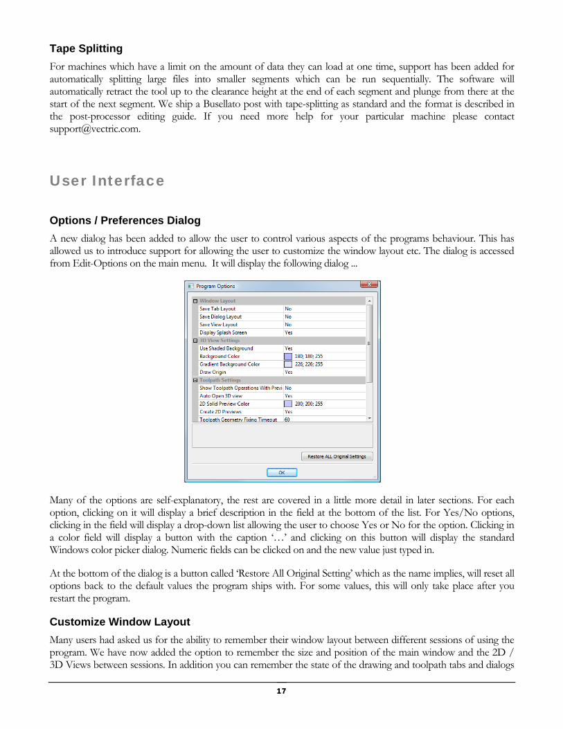
Options / Preferences Dialog
A new dialog has been added to allow the user to control various aspects of the programs behaviour. This has allowed us to introduce support for allowing the user to customize the window layout etc. The dialog is accessed from Edit-Options on the main menu. It will display the following dialog ...
Many of the options are self-explanatory, the rest are covered in a little more detail in later sections. For each option, clicking on it will display a brief description in the field at the bottom of the list. For Yes/No options, clicking in the field will display a drop-down list allowing the user to choose Yes or No for the option. Clicking in a color field will display a button with the caption ‘…’ and clicking on this button will display the standard Windows color picker dialog. Numeric fields can be clicked on and the new value just typed in.
At the bottom of the dialog is a button called ‘Restore All Original Setting’ which as the name implies, will reset all options back to the default values the program ships with. For some values, this will only take place after you restart the program.
Customize Window Layout
Many users had asked us for the ability to remember their window layout between different sessions of using the program. We have now added the option to remember the size and position of the main window and the 2D / 3D Views between sessions. In addition you can remember the state of the drawing and toolpath tabs and dialogs

18 18
such as the layer and toolpath management dialogs. The drawing and toolpath tabs can also be detached from the main interface by clicking on the header of the tab once it is open and dragging it away from the side of the screen. The tabs can be re-attached by dragging them back close to the edge, when they will snap back into position. For users with two (or more) monitors tabs and dialogs can be moved over to the second screen leaving the main screen to display just the 2D / 3D views.
Background Colors for 3D View
The colors for the background and gradient shading settings for the 3D view can now be user specified. Many users had asked for control over the colours used for the background of the 3d view. In addition many users had also requested that the gradient shading be turned off by default as it made removing the background of screen shots for use in web-pages, brochures etc. difficult.
Shortcuts
New shortcuts have been added for the Layer Control dialog (Ctrl+L) and the Join Form (J). In addition the handling of existing shortcuts while forms are open has been vastly improved. For a full list of shortcuts, click on the ‘Keyboard Shortcuts’ link at the top of the program help file.
General
Gadgets
We have introduced a new feature called ‘gadgets’ which lets Vectric produce small add-on programs which perform specialized tasks. These gadgets will be distributed from the Vectric web-site and the list of available
By default these settings are NOT remembered, but by going to the Options Dialog (Edit – Options) you can tell the program to remember these options as shown in the screenshot at the right.
To switch on an option click in the field next to the option name and select ‘yes’ from the drop-down list which will appear.
If you want to reset all the window positions, return these options to ‘No’ and restart the program.

19 19
gadgets will expand over time. The content of the gadgets menu on the main menu bar is built dynamically when the program starts by scanning the ‘Gadgets’ directory under the installation folder for the program (usually C:\Program Files\VCarve Pro V5.5\Gadgets). When a file ending with .VectricGadget, .exe or .bat is found in the folder (or sub-folder) an entry is made in the Gadgets menu allowing you to run the program by clicking on its name.
If you want direct access to a program you commonly use, just copy it into the Gadgets directory and restart VCarve Pro and it will appear on the Gadget menu. Please note that many programs require other supporting files to run. An example is Notepad.exe which can simply be copied on its own for early versions of Windows, but for later versions it needs other supporting files and will not run if you just copy notepad.exe into the Gadgets folder. To run a program like this, create a text file with the contents as shown below ..
and save its as “Run_Notepad.bat” in the Gadgets folder. When you restart the program you will have an entry called ‘”Run Notepad” (NOTE: ‘_’ characters are replaced by a space in the menu entry). Clicking on this should run Notepad.
As well as allowing direct access to other executable programs, Vectric supply a number of ‘VectricGadget’ gadgets which interact with the program to perform a particular task. A simple example is the Keyhole toolpath gadget which creates a toolpath for machining keyhole slots in the back of your job. As well as creating the toolpath, the gadget can also create vectors on a separate layer showing the position and extents of the keyhole slot.
If you run the gadget with no vectors selected, the following message will be displayed ..
This is because the gadget uses vectors you draw on your design to specify the entry points for the keyhole slots. After you have drawn suitable vectors and selected them, re-running the gadget will display the following dialog…
cd "C:\Windows" start Notepad

20 20
The gadgets are designed to be self-explanatory where ever possible and hopefully by reading the text on the dialog and viewing the results users should be able to use them pretty easily.
It is important to point out that the gadgets are NOT as polished as functionality which has been integrated into the main program. The gadget concept is intended to allow Vectric to produce simple add ons which address minority requirements without cluttering up the main interface. As the Gadget library grows over time, we do not expect users to install every gadget, but only those that may be relevant to tasks they actually perform. We ship some gadgets which help perform common tasks for people with rotary axis. If a user has no interest in rotary machining, they can delete the ‘wrapping’ gadgets from their gadgets folder and those options will no longer be available from the Gadgets menu.
Documentation and new releases for gadgets will be available from the Vectric web-site at http://www.vectric.com/WebSite/Vectric/support/gadgets.htm