wheel balancing machine - uni-trol...the manual must be kept in the proximity of the machine in a...
TRANSCRIPT

Wheel Balancing Machine
TROLL 2356LP
OPERATING MANUAL
Operating manual
Wheel balancing machine for passenger cars and motorcycles
TROLL 2356LP
Serial number …...…………………………………………………
Production year .…………………………………………………..
MANUFACTURER
Uni-Trol Sp. z o.o.
ul. Estrady 56, 01-932 Warszawa
tel./fax +4822 834 90 13-14, +4822 817 94 22
NIP 527-020-52-46
AUTHORISED SERVICE
Uni-Trol Sp. z o.o. – SERVICE
ul. Estrady 56, 01-932 Warszawa
tel./fax +4822 834 90 13-14, +4822 817 94 22
NIP 527-020-52-46

ContentsPacking, transportation and storage ..................................................................................................... 6
1. Introduction ...................................................................................................................................... 7
1.1 The manual ................................................................................................................................. 7
1.2 Preliminary work with the balancing machine ........................................................................... 7
1.3 Machine’s identification data ..................................................................................................... 8
2. Description of the balancing machine .............................................................................................. 9
2.1 Machine equipment .................................................................................................................. 10
2.2 Keyboard description ............................................................................................................... 10
2.3 Technical specification ............................................................................................................. 12
3. Safety ............................................................................................................................................. 13
3.1 General precautions .................................................................................................................. 13
4. Maintenance and scrapping of balancing machine ........................................................................ 15
4.1 Maintenance ............................................................................................................................. 15
4.1.1 Periodical maintenance ...................................................................................................... 15
4.2 Machine scrapping ................................................................................................................... 15
4.2.1 Fire protection .................................................................................................................... 16
4.2.2 Accident prevention ........................................................................................................... 16
4.2.3 Safety designing provided in the balancing machine ........................................................ 16
4.2.4 Noise evaluation ................................................................................................................ 16
5. Installation of the balancing machine ............................................................................................ 17
5.1 Installation requirements .......................................................................................................... 17
5.1.1 Power supply source requirements .................................................................................... 17
5.2 Place of installation .................................................................................................................. 17
5.2.1 Required working area ....................................................................................................... 17
5.3 Mounting car wheels’ holder .................................................................................................... 18
5.3.1 Description of the holder’s elements ................................................................................. 19
5.3.2 The clamp nut .................................................................................................................... 19
5.4 Mounting the spike holder ........................................................................................................ 19
5.5 Mounting motorcycle wheels’ holder ....................................................................................... 21
5.6 Mounting the hood ................................................................................................................... 22
5.7 Installing and connecting LCD display .................................................................................... 22
5.8 Fixing wheels on balancing machine’s holders ........................................................................ 23
5.8.1 Car wheel ........................................................................................................................... 23
5.8.2 Car wheel in spike holder .................................................................................................. 26
5.8.3 Motorcycle wheels ............................................................................................................. 27
6. Machine programs.......................................................................................................................... 28

6.1 Activating the balancing machine ............................................................................................ 28
6.2 Machine’s main menu .............................................................................................................. 28
6.3 Machine settings ....................................................................................................................... 29
6.3.1 Sound ................................................................................................................................. 29
6.3.2 Balancing ........................................................................................................................... 30
6.3.3 USG ................................................................................................................................... 30
6.3.4 Clock .................................................................................................................................. 31
6.3.5 Printing .............................................................................................................................. 31
6.3.6 Miscellaneous .................................................................................................................... 31
6.4 Balancing program ................................................................................................................... 31
6.4.1 Inputting parameter values from keyboard ........................................................................ 33
6.4.2 Selecting weight placement mode ..................................................................................... 33
6.4.3 Changing of threshold........................................................................................................ 34
6.4.4 Changing screen mode ....................................................................................................... 34
6.4.5 Selecting machine’s measurement mode ........................................................................... 34
6.4.6 “Hidden weight” program .................................................................................................. 35
6.4.7 Initiating the measurement ................................................................................................ 37
6.4.8 Automatic wheel positioning ............................................................................................. 39
6.5 Optimisation ............................................................................................................................. 39
6.5.1 Optimisation special cases ................................................................................................. 42
6.6 Calibration ................................................................................................................................ 42
6.6.1 Calibration mode selection ................................................................................................ 43
6.6.2 Calibration using the device .............................................................................................. 43
6.6.3 Calibration using a wheel .................................................................................................. 43
6.6.4 Balancing a wheel before calibrating with it ..................................................................... 44
7. Adjuster .......................................................................................................................................... 45
7.1 Working with adjuster with weight placement mode selected ................................................. 46
7.1.1 Adjuster mode .................................................................................................................... 46
7.1.2 EASY mode ........................................................................................................................ 47
7.2 Automatic weight placement selection ..................................................................................... 49
7.2.1 EASY mode and automatic weight placement selection .................................................... 50
8. User memory .................................................................................................................................. 51
8.1 Memory reading ....................................................................................................................... 51
8.2 Saving to memory .................................................................................................................... 52
8.3 Editing the memory bank name................................................................................................ 52
9.Diagnostics and fault detection ....................................................................................................... 53

5
Packing, transportation and storage
ATTENTION: All operations concerning packing, lifting, moving, transporting and
unpacking must be carried out by qualified personnel only.
Packing
The balancing machine is sent as a complete piece of equipment (quick change holder, balancing
machine, protective hood, operating manual). The balancing machine can be packed in a few
different ways:
- pallet + stretch foil + carton box
- pallet + stretch foil
- pallet + carton box
Transport
The package can be lifted or displaced by fork-lift or pallet trucks. Once the cargo arrives at its
destination, it is recommended to check if its contents have not been damaged during transportation.
It is also recommended to check the conformity of the delivery with its bill of landing. In case of
non-conformity or transportation damages it is necessary to inform without delay the responsible
person or carrier about it. Moreover, the loading should be done with extreme precautions and
consideration.
Storage
The machine should be stored in a dry room free of dust.

6
1. Introduction
WARNING: This manual is intended for personnel licensed to service the balancing
machine (operator) and those who carry out current maintenance. Before starting any
operations concerning the balancing machine or the package, one should carefully
study the manual. It contains important information concerning personal security of the
operators and maintenance personnel as well as balancing machine’s operation.
1.1 The manual
For proper usage of this manual, the following should be applied:
The manual must be kept in the proximity of the machine in a place of easy access.
The manual must be kept in a dry place.
The manual must be used properly with care not to damage it.
It is forbidden for operators who have not studied this manual to work with a balancing
machine.
This manual is an integral part of the balancing machine and should always accompany the machine
even if it is going to be sold.
ATTENTION: It is strongly advised to read carefully and repeatedly chapter 3 in
which very important information and warnings concerning safety are contained.
WARNING: Illustrations contained in this manual present typical machine parts. It is
possible for manufactured parts to slightly differ from those illustrated in this manual.
1.2 Preliminary work with the balancing machine
ATTENTION: Lifting, transportation, unpacking, assembly, installation, putting in
motion, preliminary adjustment and testing, maintenance repairs, technical inspections,
do not require the presence of service personnel but must be carried out with extreme
precaution.
The manufacturer does not bear any responsibility for personnel injuries or vehicle and
other object damages if any of the above mentioned operations will be performed not
according to the service manual or the balancing machine was used in an improper
way.
In the manual only the aspects of the servicing and security which can help operators and servicing
personnel in a better understanding of the construction and working of the balancing machine and to
allow them to use it the best way possible were enumerated.

7
To understand the vocabulary used in the manual, operators must possess specific experience in
servicing, maintenance, repairs, workshop works and ability to correctly decode all drawings and
descriptions contained in the manual. Operators must also know general and detailed safety
requirements obligatory in the installation country.
The word “operator” used in this manual should be understood in the following manner:
Operator: a person licensed to service a balancing machine.
1.3 Machine’s identification data
When contacting our authorized service, providing the model and serial number aids in getting help
from service Staff and quickens the process of sending spare parts. For convenience and clarity, a
table is presented below. If any differences between the table below and the name plate on the
machine, data on the name plate apply.
www.unitrol.pl
Uni-Trol Sp. z o.o. ul. Estrady 56, 01-932 Warszawa
Zakład Produkcyjny - Serwis – - Salon Sprzedaży
/ +22 8179422
e-mail: [email protected]
Wheel balancing machine
TROLL 2356 LP
Serial number: 01/14
Technical data : Power supply 230 V / 50 Hz Electric motor power 80 W Noise level < 67 dB Max wheel weight 60 kg Max outer dimensions 1170x1000x1450 mm Total machine weight 85 kg
EEE waste
Manufactured in Poland

8
2. Description of the balancing machine TROLL 2356LP balancing machines are designed for balancing of car and motorcycle1 wheels in a
single measurement cycle. Original construction solutions assure safe, simple and comfortable
operating of the machine as well as reliability and fast wheel balancing.
TROLL 2356LP balancing machine is equipped with:
Quick mounting holder,
Hood,
LCD display,
Sound speaker,
Automatic calibration program,
“Hidden weight” program,
Optimisation program,
Imbalance recalculation program,
ALU programs for working with aluminium rims,
User memory bank.
The balancing machine has following attributes:
modern measurement system with a computer system for data processing to ensure fast and
complete measurement with great accuracy,
the possibility to choose a program for wheel handling (also for light aluminium rims) with
every type of balancing weights – hammered or adhesive,
the possibility of regulating balancing accuracy, according to the wheel's mass and state,
easy programming and measurement with an ergonomic keyboard design,
versatility of special holders enabling attachment of almost all wheel types,
automatic calibration system that allows the machine to regulate the measurement system on
its own if operator assumes incorrect imbalance indications of the machine,
ability to adjust user interface and machine mode according to operator’s own preferences.
1 Motorcycle holder required.

9
2.1 Machine equipment
Fig. 2.1 Balancing machine – elements description
No Name
1 Hood
2 Arm of the hood
3 Collar of hood’s axis
4 LCD display
5 Video signal
6 Display’s support
7 Display’s angle regulator
8 Power cable
9 Holders for additional elements
10 Machine’s main switch
11 Keyboard
12 Adjuster with laser point
13 Laser line
14 Ultrasonic sensor
Table 2.1 – description of balancing machine’s elements from fig. 2.1
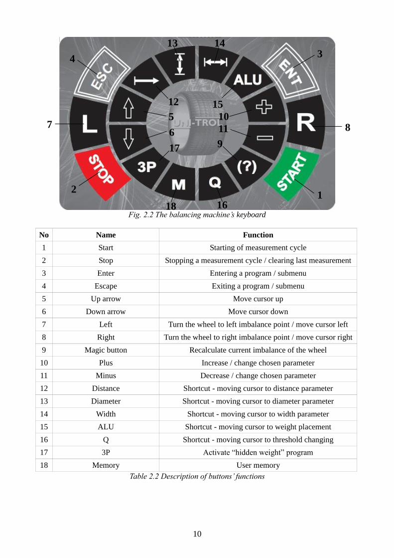
2.2 Keyboard description
Figure 2.2 shows the balancing machine’s keyboard (11 in fig. 2.1). All functions of each button
have been described in table 2.2.
1
4
5 2 3
8
9
6
7
10 12 13
11
14
10
Fig. 2.2 The balancing machine’s keyboard
No Name Function
1 Start Starting of measurement cycle
2 Stop Stopping a measurement cycle / clearing last measurement
3 Enter Entering a program / submenu
4 Escape Exiting a program / submenu
5 Up arrow Move cursor up
6 Down arrow Move cursor down
7 Left Turn the wheel to left imbalance point / move cursor left
8 Right Turn the wheel to right imbalance point / move cursor right
9 Magic button Recalculate current imbalance of the wheel
10 Plus Increase / change chosen parameter
11 Minus Decrease / change chosen parameter
12 Distance Shortcut - moving cursor to distance parameter
13 Diameter Shortcut - moving cursor to diameter parameter
14 Width Shortcut - moving cursor to width parameter
15 ALU Shortcut - moving cursor to weight placement
16 Q Shortcut - moving cursor to threshold changing
17 3P Activate “hidden weight” program
18 Memory User memory
Table 2.2 Description of buttons’ functions
1
8
2
7
4 3
5
6
17
18 16
9
10
15 12
14 13
11

11
2.3 Technical specification
Wheel diameter 10''-26'' Wheel width 2''-20'' Imbalance indication accuracy 1g Imbalance location signal accuracy 3° Measurement time 7s Wheel weight Up to 60kg Drive motor rating 80W Spindle rotation speed during measurement 160 rpm Overall dimensions
No hood, no display, with wheel holder 1000 x 580 x 900 mm With hood and display, hood closed 1170 x 850 x 1260 mm With hood and display, hood opened 1170 x 1000 x 1450 mm
Total machine weight approx. 85 kg Power supply 230V/50Hz Average level of acoustic pressure LAV 65 dBA

12
3. Safety
WARNING: This chapter should be read carefully because it contains important
information for operators and other persons concerning hazards of using the balancing
machine in an inappropriate way.
Below are explanations concerning hazards and risks which can occur during balancing machine
operating and maintenance. General and detailed precautions are given for avoiding potential
hazards.
Warning: The TROLL 2356LP balancing machine was designed for the balancing of
car and motorcycle wheels in one measurement cycle. Any work with the balancing
machine should be preceded by comprehensive reading and understanding of this
manual. Any other type of usage of this balancing machine is not allowed. In particular,
the balancing machine is not intended for balancing other elements or balancing truck
wheels.
ATTENTION: The producer and the dealer do not bear any responsibility for
personnel injuries or vehicle and other objects’ damages in case of improper or
unauthorized use of the balancing machine.
Any operation of the balancing machine is not allowed without prior closing of the
hood. Not satisfying the above mentioned recommendations can result in serious
human injuries and irreparable balancing machine's damages and wheel damages.
3.1 General precautions
It is required that the operator and the maintenance technician adapt safety rules obligatory in the
country of installation. Moreover, the operator and the maintenance staff should read all the
information regarding safety placed on the machine and all the information included in this manual.
Risk of electric shock – hazard of electric shock can occur in those balancing machine areas, where
electric cables are placed. Use of water sprayers, vapour sprayers (high pressure washing units),
dissolvers and painting equipment is not allowed in vicinity of the balancing machine and in
particular they should not be in contact with the control unit.
Impact risk – during operation of the machine here is a risk of some parts of the balancing machine
hitting the operator. With the protective screen open, personnel must preserve all precautions to
avoid hitting against machine parts.
Risk of wheel easing – before balancing starts, one should check if the wheel is properly and firmly
fixed in its holder.

13
ATTENTION: It is forbidden to unscrew the wheel during machine work!
It is forbidden to leave the machine unattended during work!
It is forbidden to use wheels excessing the maximum wheel weight!
It is forbidden to initiate a measurement with an incorrectly mounted wheel!
Skid risk – this hazard can be caused by floor contamination with grease in the proximity of the
balancing machine. The area under the balancing machine, the holders and the area near them must
be kept clean at all times. All the oil spots should be removed instantly.
Hazard caused by poor illumination – the operator and the maintenance technician must have the
possibility to check if all areas of the balancing machine are properly and uniformly illuminated
according to the regulations applied in the installation place.
Risk of balancing machine defect during work – to produce a reliable and safe balancing
machine, the manufacturer applied suitable materials and manufacturing techniques that are
necessary for this type of equipment. Nevertheless the balancing machine should be operated
according to the producer’s recommendations. Technical service (after warranty period) and other
maintenance works described in chapter 4.1 “Maintenance” should be carried out with specified
periodicity.
ATTENTION: All operations of the balancing machine contrary to its function can
cause danger, serious damage or accidents to anybody near the machine. It is crucial to
scrupulously observe all recommendations contained in this manual concerning
maintenance and safety.
Risk involving machine’s moving parts – During any kind of operations all limbs should be kept
as far from moving parts as possible at all times. Necklaces, bracelets and loose clothes as well as
long hair may cause potential danger to the operator. It is mandatory to take any jewellery off, wear
clothes fit close to body and use headgear. The operator should use appropriate shoes to prevent any
lower limb injuries.
Risk caused by laser radiation – The laser point adjuster system is equipped with two low-power
laser diodes. The machine is designed in such a way that both laser diodes are never pointing
upwards. The main principle regarding usage of the laser adjuster is avoiding eye and skin contact
with radiation and – most importantly – not looking straight into the lasers.

14
4. Maintenance and scrapping of balancing machine
4.1 Maintenance
Maintenance should be conducted by experienced personnel with knowledge concerning the
principles of balancing machine’s operation. During the maintenance process one should preserve
all precautions in order to avoid any accidental start of the balancing machine. The master switch
should be pushed out and its light should be off. One should also adhere to all instructions given in
chapter 3.
4.1.1 Periodical maintenance
In order to keep the balancing machine in a good operational state one should observe the below
mentioned indications:
Clean your balancing machine at least once a month without using any chemical washing
agents or high pressure spray guns.
Check the operational state of all equipment periodically.
Lubricate all holders periodically and keep them clean.
Check the state of all cords once a year.
ATTENTION: Disregard of these recommendations will dismiss the manufacturer
from any responsibility included in warranty.
WARNING: Always remove all dirt from the area near the balancing machine.
4.2 Machine scrapping
ATTENTION: During machine scrapping one should preserve all precautions
described in chapter 3, also applied during assembly.
As well as assembly, disassembly has to be executed by trained personnel only. All metal parts
should be utilized as metal scrap. In all cases of machine scrapping, the utilization of all materials
has to be conducted according to the rules applied in the country of installation.
One should also notice that for tax purposes, effective machine scrapping should be documented in
reports and forms according to the rules applied in the installation country.

15
4.2.1 Fire protection
The machine does not constitute fire hazard. Nevertheless, room in which the balancing machine is
installed, has to fulfil requirements of fire protection regulations applied in the country of
installation.
Always keep one or more portable fire extinguishers within the operator's reach (operator zone), in
order to prevent any fire hazard.
4.2.2 Accident prevention
During lifting/lowering, shifting, installing, assembling and disassembling of the balancing
machine, one should preserve all precautions provided in regulations concerning accident
prevention applied in the installation country. Moreover, all regulations concerning fork-lift trucks
have to be preserved.
4.2.3 Safety designing provided in the balancing machine
The machine has been equipped with a hood, which protects the operator with revolving parts of the
balancer. The machine has been designed in such manner as not to initiate a measurement by
accident or start one with the hood opened.
Each measurement initiation has to be preceded with pressing the START button, which starts only
a single measurement (assured by software). Due to many safety design constructs, it is impossible
for the machine to initiate any kind of measurement sequence on its own.
If any other incidental situations not mentioned in this operating manual occur, the operator is to
immediately stop working with the machine, call authorized service and describe the problem.
4.2.4 Noise evaluation
Noise emission approximations where conducted in ordinary surroundings for a wheel balancing
machine using environmental correction, defined and simplified by norm PN-EN ISO 11202.
Measurements where made using a 20” wheel, weight approximately 35kg and in correct working
conditions, i.e. nominal power supply conditions.
Measurements using a calibrated microphone where performed during a period from start of
measurement and reaching maximal rotation speed to turning the drive motor off and stopping the
wheel completely. For evaluation purposes an average from a couple of maximised measurements
has been taken.
Average level of acoustic pressure Lav = 65 dBA .
16
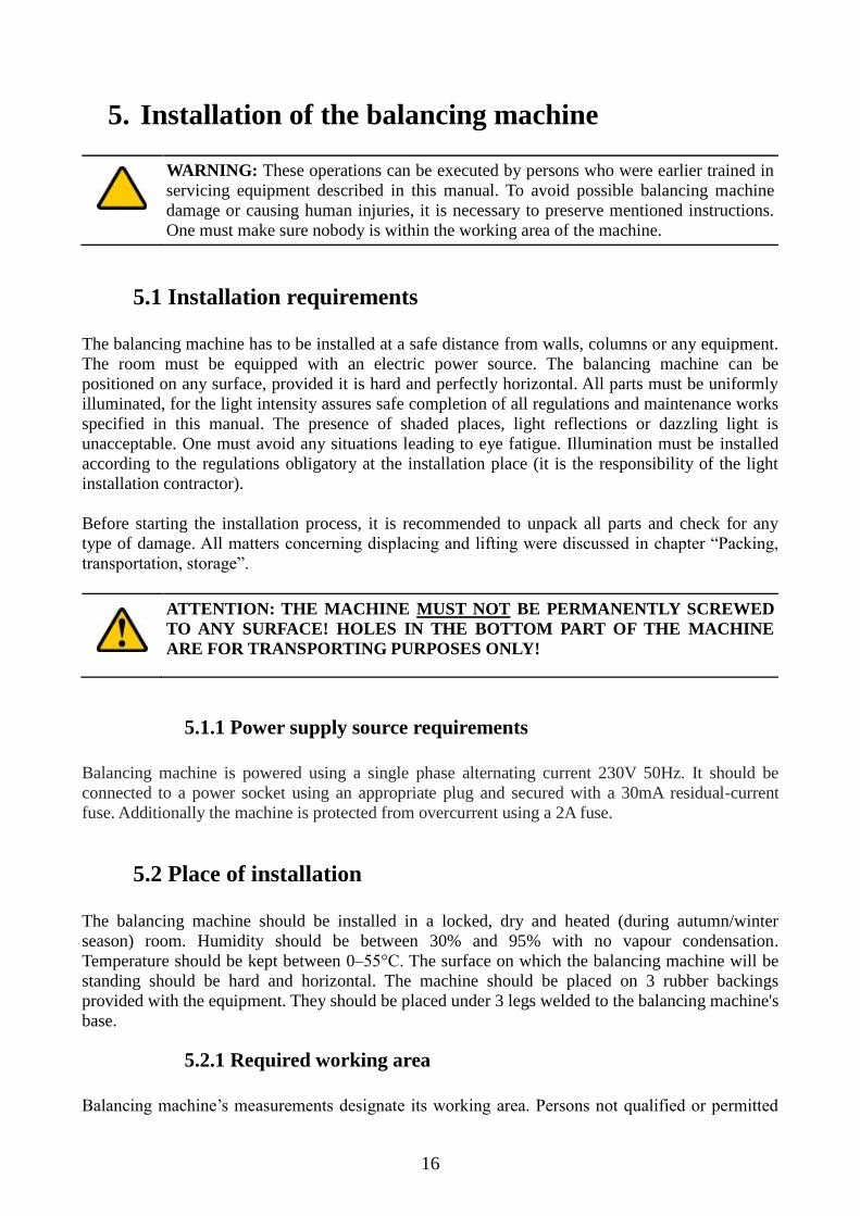
5. Installation of the balancing machine
WARNING: These operations can be executed by persons who were earlier trained in
servicing equipment described in this manual. To avoid possible balancing machine
damage or causing human injuries, it is necessary to preserve mentioned instructions.
One must make sure nobody is within the working area of the machine.
5.1 Installation requirements
The balancing machine has to be installed at a safe distance from walls, columns or any equipment.
The room must be equipped with an electric power source. The balancing machine can be
positioned on any surface, provided it is hard and perfectly horizontal. All parts must be uniformly
illuminated, for the light intensity assures safe completion of all regulations and maintenance works
specified in this manual. The presence of shaded places, light reflections or dazzling light is
unacceptable. One must avoid any situations leading to eye fatigue. Illumination must be installed
according to the regulations obligatory at the installation place (it is the responsibility of the light
installation contractor).
Before starting the installation process, it is recommended to unpack all parts and check for any
type of damage. All matters concerning displacing and lifting were discussed in chapter “Packing,
transportation, storage”.
ATTENTION: THE MACHINE MUST NOT BE PERMANENTLY SCREWED
TO ANY SURFACE! HOLES IN THE BOTTOM PART OF THE MACHINE
ARE FOR TRANSPORTING PURPOSES ONLY!
5.1.1 Power supply source requirements
Balancing machine is powered using a single phase alternating current 230V 50Hz. It should be
connected to a power socket using an appropriate plug and secured with a 30mA residual-current
fuse. Additionally the machine is protected from overcurrent using a 2A fuse.
5.2 Place of installation
The balancing machine should be installed in a locked, dry and heated (during autumn/winter
season) room. Humidity should be between 30% and 95% with no vapour condensation.
Temperature should be kept between 0–55°C. The surface on which the balancing machine will be
standing should be hard and horizontal. The machine should be placed on 3 rubber backings
provided with the equipment. They should be placed under 3 legs welded to the balancing machine's
base.
5.2.1 Required working area
Balancing machine’s measurements designate its working area. Persons not qualified or permitted

17
to operate it are not allowed in this area. Maximal requirements concerning the working area are
2870x3000 mm given minimal distance to walls, what has been presented in fig. 5.1. Numbers 1
and 2 designate operator’s working setting.
Fig. 5.1 Machine surroundings: minimal distance from walls and operator’s working setting.
5.3 Mounting car wheels’ holder
WARNING: The balancing machine may be delivered with an already mounted
holder.
An assembled holder for car wheels with rims having a central mounting hole is shown in fig. 5.2.
Before mounting the holder, clean the cone surface of the spindle (1) and the surface of the holder
(2). Place the holder on the spindle so the position of the markers (3) on the spindle's snug and on
the holder is aligned as shown in figure 5.2. Lastly, screw the holder onto the spindle with the bolt
(4).
ATTENTION: Careful cleaning of the cone surface and maintaining the position of
the holder's markers is a crucial condition for accurate measurement.
1000mm
1000mm
1000mm 700mm
1 2
3000mm
2870mm

18
Fig. 5.2 Holder for car wheels (with no nut, cone or bushings)
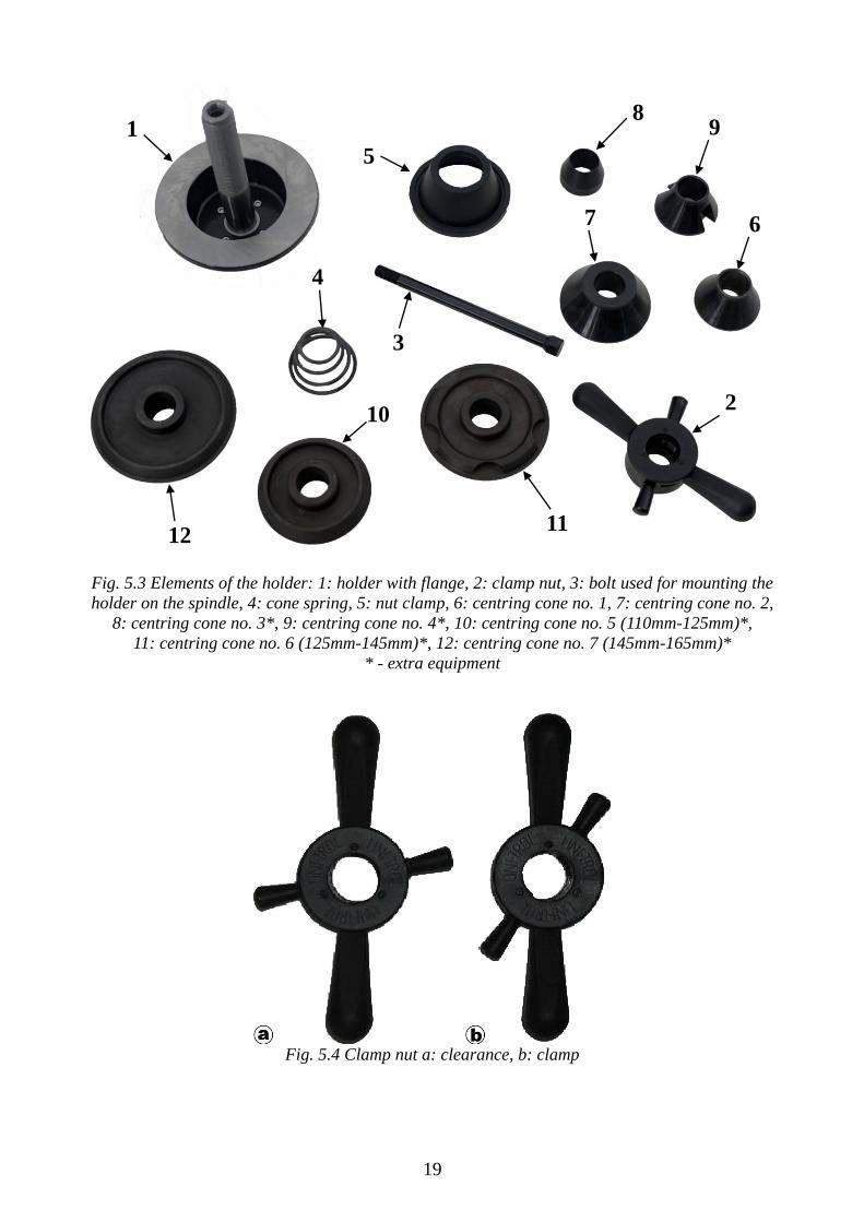
5.3.1 Description of the holder’s elements
The fast mounting holder was designed for car wheels with rims having a central hole. Figure 5.3
shows all of the holder’s elements with their description.
5.3.2 The clamp nut
Figure 5.4 shows the clamp nut in two positions. In position a (clearance) one can freely move the
nut along the thread. In position b (clamp) the nut can be screwed on the thread of the shaft.
5.4 Mounting the spike holder
ATTENTION: Spike holder is not standard equipment and – if needed – can be
purchased separately.
Spike holder, presented and described in figure 5.5, is used for wheels without a central hole.
Wheels having 3, 4, 5 and 6 holes can be mounted on the holder.
Due to the fact that mounting a spike holder is dependent on the balanced wheel, the whole
procedure has been described in chapter 5.8.2.
19
Fig. 5.3 Elements of the holder: 1: holder with flange, 2: clamp nut, 3: bolt used for mounting the
holder on the spindle, 4: cone spring, 5: nut clamp, 6: centring cone no. 1, 7: centring cone no. 2,
8: centring cone no. 3*, 9: centring cone no. 4*, 10: centring cone no. 5 (110mm-125mm)*,
11: centring cone no. 6 (125mm-145mm)*, 12: centring cone no. 7 (145mm-165mm)*
* - extra equipment
Fig. 5.4 Clamp nut a: clearance, b: clamp
1
2
3
4
6 7
5
8 9
10
11 12
20
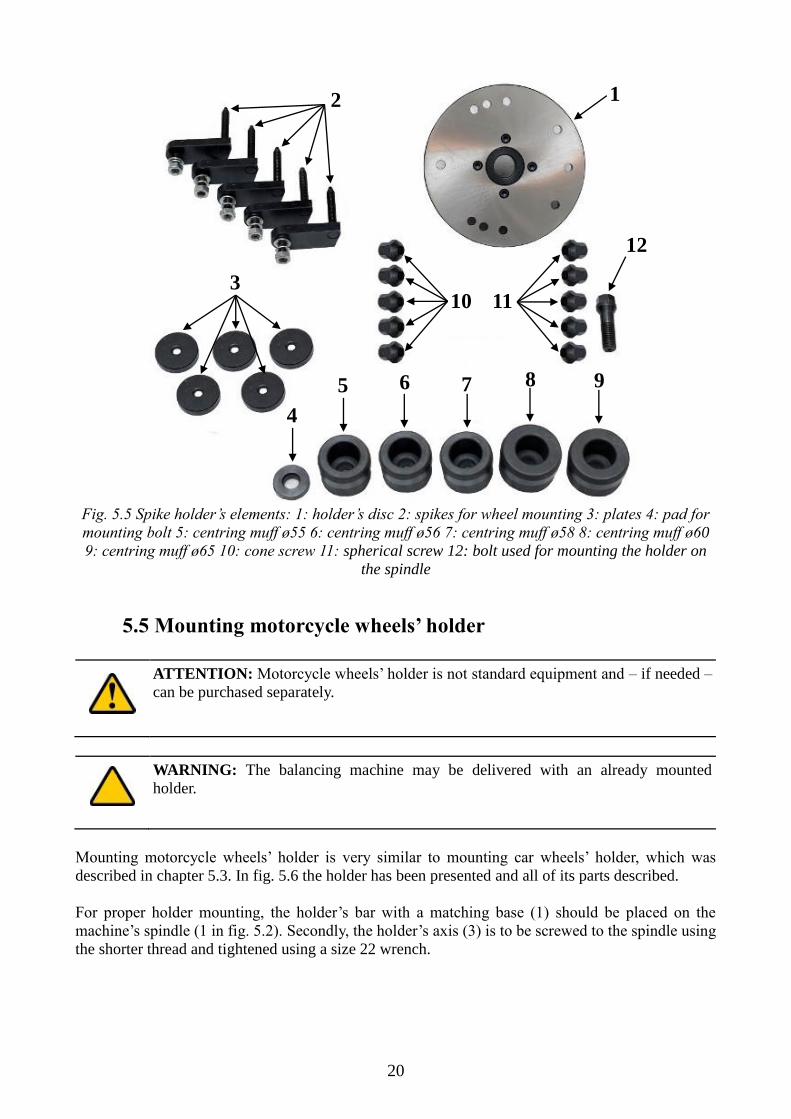
Fig. 5.5 Spike holder’s elements: 1: holder’s disc 2: spikes for wheel mounting 3: plates 4: pad for
mounting bolt 5: centring muff ø55 6: centring muff ø56 7: centring muff ø58 8: centring muff ø60
9: centring muff ø65 10: cone screw 11: spherical screw 12: bolt used for mounting the holder on
the spindle
5.5 Mounting motorcycle wheels’ holder
ATTENTION: Motorcycle wheels’ holder is not standard equipment and – if needed –
can be purchased separately.
WARNING: The balancing machine may be delivered with an already mounted
holder.
Mounting motorcycle wheels’ holder is very similar to mounting car wheels’ holder, which was
described in chapter 5.3. In fig. 5.6 the holder has been presented and all of its parts described.
For proper holder mounting, the holder’s bar with a matching base (1) should be placed on the
machine’s spindle (1 in fig. 5.2). Secondly, the holder’s axis (3) is to be screwed to the spindle using
the shorter thread and tightened using a size 22 wrench.
1 2
3
4
5 6 7 8 9
12
11 10
21
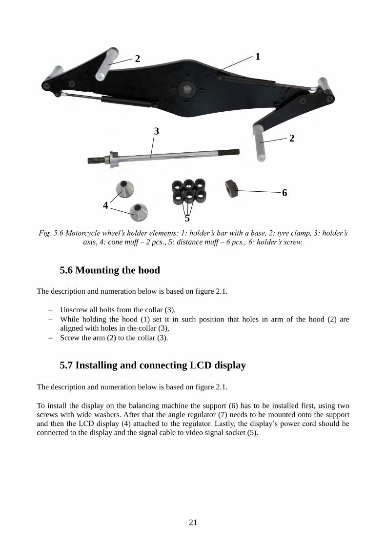
Fig. 5.6 Motorcycle wheel’s holder elements: 1: holder’s bar with a base, 2: tyre clamp, 3: holder’s
axis, 4: cone muff – 2 pcs., 5: distance muff – 6 pcs., 6: holder’s screw.
5.6 Mounting the hood
The description and numeration below is based on figure 2.1.
Unscrew all bolts from the collar (3),
While holding the hood (1) set it in such position that holes in arm of the hood (2) are
aligned with holes in the collar (3),
Screw the arm (2) to the collar (3).
5.7 Installing and connecting LCD display
The description and numeration below is based on figure 2.1.
To install the display on the balancing machine the support (6) has to be installed first, using two
screws with wide washers. After that the angle regulator (7) needs to be mounted onto the support
and then the LCD display (4) attached to the regulator. Lastly, the display’s power cord should be
connected to the display and the signal cable to video signal socket (5).
1 2
2 3
4
5
6
22
5.8 Fixing wheels on balancing machine’s holders
5.8.1 Car wheel
If there is other holder than for car wheels mounted (fig. 5.2), it should be replaced with car wheels’
holder as described in chapter 5.3.
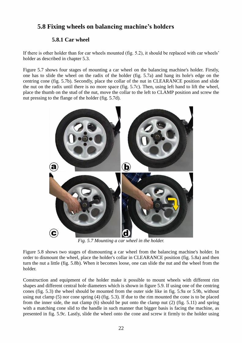
Figure 5.7 shows four stages of mounting a car wheel on the balancing machine's holder. Firstly,
one has to slide the wheel on the radix of the holder (fig. 5.7a) and hang its hole's edge on the
centring cone (fig. 5.7b). Secondly, place the collar of the nut in CLEARANCE position and slide
the nut on the radix until there is no more space (fig. 5.7c). Then, using left hand to lift the wheel,
place the thumb on the stud of the nut, move the collar to the left to CLAMP position and screw the
nut pressing to the flange of the holder (fig. 5.7d).
Fig. 5.7 Mounting a car wheel in the holder.
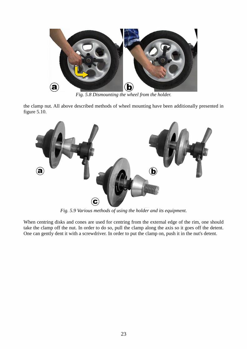
Figure 5.8 shows two stages of dismounting a car wheel from the balancing machine's holder. In
order to dismount the wheel, place the holder's collar in CLEARANCE position (fig. 5.8a) and then
turn the nut a little (fig. 5.8b). When it becomes loose, one can slide the nut and the wheel from the
holder.
Construction and equipment of the holder make it possible to mount wheels with different rim
shapes and different central hole diameters which is shown in figure 5.9. If using one of the centring
cones (fig. 5.3) the wheel should be mounted from the outer side like in fig. 5.9a or 5.9b, without
using nut clamp (5) nor cone spring (4) (fig. 5.3). If due to the rim mounted the cone is to be placed
from the inner side, the nut clamp (6) should be put onto the clamp nut (2) (fig. 5.11) and spring
with a matching cone slid to the handle in such manner that bigger basis is facing the machine, as
presented in fig. 5.9c. Lastly, slide the wheel onto the cone and screw it firmly to the holder using
23
he
Fig. 5.8 Dismounting the wheel from the holder.
the clamp nut. All above described methods of wheel mounting have been additionally presented in
figure 5.10.
Fig. 5.9 Various methods of using the holder and its equipment.
When centring disks and cones are used for centring from the external edge of the rim, one should
take the clamp off the nut. In order to do so, pull the clamp along the axis so it goes off the detent.
One can gently dent it with a screwdriver. In order to put the clamp on, push it in the nut's detent.

24
Fig. 5.10 Different ways of mounting wheels for various cones and their configurations.

25
Fig. 5.11 Nut with mounted clamp.
5.8.2 Car wheel in spike holder
If any holder other than the spike holder is mounted, it should be dismounted.
If the rim does not have a central hole, the spike holder should be used. Figure 5.12 presents four
stages of mounting a wheel onto the described holder. Firstly, depending on the wheel, all muffs
should be checked (5÷9 in fig. 5.5) to see which one fits best to the hole inside the rim. If none of
them fit or there is no hole inside the rim, the pad (4 in fig. 5.5) should be used. Secondly, the disc
should be mounted onto the machine’s spindle and screwed using the provided bolt (12 in fig. 5.5)
with the selected muff or pad, as presented in fig. 5.12a.
Fig. 5.12 Mounting a wheel without a central hole on the spike holder.
Depending on the number of holes in the rim, place the spikes (2 in fig. 5.5) on the disc according
to the numbers imprinted on the back. For example, if the rim has 5 holes, all spikes should be

26
placed in holes which have the number 5 at the back of the disc (fig. 5.12b), if it has 6 holes, then 3
spikes should be placed in holes with the number 3 at the back of the disc and put into the rim
through every second hole. The spikes should be screwed using the provided nuts and washers in
such manner that the spikes are firmly screwed, but can be tightly rotated (first the flat washer, next
the spring washer and lastly the nut). If enough free space is available, place the plates onto the
spikes with the indentation facing outwards and set them in a position which makes it possible to
put the wheel on the holder (fig. 5.12c).
WARNING: If any problems arise with spikes placement in relation to the rim holes
during wheel mounting, the holder can be firstly set – before putting it on the spindle –
on a dismounted wheel.
Depending on the female screws used in the car for wheel mounting, either cone screws (10 in fig.
5.5) or spherical screws (11 in fig. 5.5) should be applied to install the wheel on the holder (5.12d).
5.8.3 Motorcycle wheels
If any holder other than the motorcycle wheels’ holder is mounted, it should be exchanged with the
motorcycle holder (fig. 5.6) as described in chapter 5.5.
Figure 5.13 presents four steps of installing a motorcycle wheel in the balancing machine’s holder.
Firstly, the operator must make sure that tyre clamps (2 in fig. 5.6) are opened, then slide one of
cone muffs (4 in fig. 5.6) on the axis (fig. 5.13a). Next, after sliding the wheel to the end of the axis
and placing it on the cone (fig. 5.13b) put the other cone muff on the axis in such way that it enters
the wheel’s bearing. For the wheel to be tightly mounted on the holder, distance muffs (5 in fig. 5.6)
should be placed after the second cone so that there is enough thread at the end of the axis for the
holder’s screw (6 in fig. 5.6), like in fig. 5.13c. When everything is tightly mounted and the wheel is
not loose, close the tyre clamps so they touch the wheel’s tyre (fig. 5.13d).
fig. 5.13 Mounting motorcycle wheel on the holder.

27
6. Machine programs
6.1 Activating the balancing machine
In order to activate the balancing machine, the power button (10 in fig 2.1) must be pushed in so
that the light in it turns on. The machine generates a short signal and goes straight to the
measurement screen. One of five screens can be shown on the LCD display:
Main menu (procedure selection),
Balancing program,
Optimisation,
Calibration,
Machine settings.
In the following chapters all of the programs and their corresponding screens are described.
6.2 Machine’s main menu
The main menu, containing the machine’s programs, is presented in fig. 6.1 and makes it possible to
access to one of four above described screens. To activate one of the programs set the cursor using
up and down arrows on the keyboard and press Enter. To go back to the main menu, simply press
the Esc key.
Fig. 6.1 – Main menu screen

28
6.3 Machine settings
For the operator’s convenience, a settings menu has been provided (fig. 6.2) which gives the means
of changing some of the machine’s preferences and parameters. The menu consists of following
submenus:
Sound,
Balancing,
USG,
Clock,
Printing1,
Miscellaneous.
Available values for most of the settings are on or off (other possible values are described in
remaining subchapters). If a certain option is not available, the machine will display N/A (not
available).
Fig. 6.2 – Machine settings screen.
6.3.1 Sound
Sound settings are for alternating volume and lector values2. To change any of those, move the
cursor using up and down arrow keys to Sound if it is not there and press Enter. Next, move the
cursor on the newly displayed menu and change the value of the setting chosen using Plus and
Minus keys.
1 available only in certain machine models.
2 2 available only in machines with one language.

29
ATTENTION: Turning the lector option off does not turn the system sounds off, only
the lector. For operator safety, it is not possible to turn warning and signalising sounds
off.
Volume has a four-step scale and should be set so the operator can hear all the signals without any
problems. Default value for volume setting is ¾, lector (if available) is by default turned on.
6.3.2 Balancing
The balancing menu helps setting options regarding the measurement. It concerns displaying the
result, automatic starting of measurement after closing the hood, adhesive weight placing method
for modes 4, 5 and 7 in table 6.2 and a counter for all performed measurements. Displaying the
result gives 2 possibilities: 1g or 5g. The option, as the name indicates, forces the machine to
calculate the imbalance with accuracy of 1g or rounding to multiples of 5g for the second option.
For instance, if the evaluated imbalance is 11g, then for the second option active the machine will
display 10 as a result, and for imbalance equal to 14g the balancer will round it to 15. The default
option is 1g.
ATTENTION: For the second option active (5g) there is a possibility of result
variation between measurements. It may happen if, for example, two consecutive
measurements are performed and after the first measurement the result is 10, but after
the second measurement 15 – even though no additional weight has been put on the
wheel. Such situation may occur if the result is close to the average of the two values.
To check the result before rounding without going to settings and changing this option
to 1g it is enough to hold the Magic button (9 in fig. 2.2) for a while, until the result
starts blinking. When the button is released, the result is again displayed rounded.
Second option relates to automatic starting of measurement after closing the hood. If this option is
turned on, the balancing program screen is displayed and the hood is closed, the machine will
automatically invoke a measurement without the need of pressing the Start button. By default this
option is turned on.
Third option – Adhesive weights – is associated with placing adhesive weight on the rim for weight
placement modes 4, 5 and 7 in table 6.2. 2 options are available: Adjuster and Easy mode. Adjuster
mode coerces the operator to place the weights using laser pointers. For Easy mode, the weights are
placed under the wheel holder’s disc, on the bottom. The adjuster’s operation has been described
in detail in chapter 7.
Fourth option is more of an information about performed measurements. After moving the cursor to
this menu and pressing Enter two positions appear: “All measurements” and “Complete
measurements”. The first position shows the number of uninterrupted measurement cycles and the
second one shows the number of all cycles which resulted with no imbalance (balanced wheel).
To clear both values, press the Memory button.
6.3.3 USG
USG option makes the operator decide whether the ultrasonic sensor installed on the machine’s
hood is to measure width of a mounted wheel during the hood’s closure after finishing adjuster

30
measurements. To activate or deactivate the ultrasonic sensor measurement move the cursor to
“USG Sensor” and using Plus and Minus keys select the desired setting. By default the sensor is
turned on.
6.3.4 Clock
Clock menu is either for setting or checking time and date. To change current time and/or date move
the cursor to “Set time/date” using arrow keys and press Enter. When in time setting program, move
the cursor using L and R keys to select one of the variables (from the left: day, month, year, hours,
minutes), change the value using Plus or Minus keys on the keyboard and either apply changes
using the Memory key or cancel with the Escape key.
ATTENTION: Machine does not check the correctness of input date. Theoretically, it
is possible to input February 31st, but it may cause errors in time display on the
machine programs’ screens. It is advised to thoroughly check whether all input data is
correct.
6.3.5 Printing
This option is not available in this machine model.
6.3.6 Miscellaneous
The miscellaneous section provides settings for display brightness, setting all options to factory
defaults, changing the language3 and displaying machine details. To adjust screen brightness move
the cursor to desired option and while using Plus and Minus keys the screen’s brightness will
alternate.
Bringing back factory settings sets all saved parameters to zero and brings all options to primary
values which were present during machine’s first start-up.
ATTENTION: Bringing back factory defaults is an IRREVERSABLE operation,
after which machine recalibration will be required. Use this option only in absolute
necessity.
To change the current language set the cursor to the desired option and press the Enter key. From
the list select a language of your choosing using the up and down arrow keys and press Enter. All
the menus (and the alphabet if necessary) will change instantly.
“Machine info” option gives the operator the ability to check the balancing machine’s details, which
are always helpful when contacting authorized service.
3 Changing the displayed language is only possible if lector is not available

31
6.4 Balancing program
The balancing program’s screen has been presented in fig. 6.3. The left section contains a menu for
setting wheel parameters or alternating measurement properties. Table 6.1 describes all elements of
the menu as well as other sections of the screen.
Fig. 6.3 – Balancing program screen.
Number Description
1 Distance from the machine to balanced wheel
2 Diameter of the balanced wheel
3 Width of the balanced wheel (weight span)
4 Selection of weight placement mode
5 Changing of threshold
6 Changing screen mode
7 Measurement mode (car or motorcycle wheels)
8 “Hidden weight” program
9 Initiate measurement
10 Imbalance value of internal plane of the wheel
11 Imbalance location of internal plane of the wheel
12 Imbalance value of external plane of the wheel
13 Imbalance location of external plane of the wheel
14 Clock
Table 6.1 – Description of balancing program screen elements
1
2
3
4
5
6
7
8
9
10 12
11
13
14

32
ATTENTION: Before proceeding with any measurements, chapter 7 describing the
adjuster principles should be read thoroughly. Without the knowledge of wheel
parameters’ inputting using the adjuster, they may be incorrectly initiated which will
deteriorate imbalance calculations during a measurement.
6.4.1 Inputting parameter values from keyboard
To input wheel’s distance to the machine, its diameter and width, use the arrow keys or one of
shortcut keys (positions 1-3 in fig. 6.3) to set the cursor position on the chosen element. Next, using
the Plus and Minus keys, set the desired value. After each button press the value will either increase
or decrease, which will be signalled with a sound from the speaker. If the button is held for a longer
time, the parameter value will change quicker.
6.4.2 Selecting weight placement mode
In order to select the weight placement mode, use the arrow keys or the ALU shortcut key (4 in fig.
6.3) to set the cursor position. Use the Plus and Minus keys to set the weight placement mode. After
each button push the setting will change, which will be signalled with a sound from the speaker. If
the key is held longer, the setting will change more rapidly. Table 6.2 presents all possible weight
placement modes for car wheels (numbers 1-5) and two motorcycle wheel modes (numbers 6 and
7).
ATTENTION: It may happen that instead of red weights in the ALU section on the
screen question marks are present. It is an automatic weight placement program which
is described in detail in chapter 7.2.
No Setting Description
1
Balancing a car wheel with hammered weights on both sides of the
rim.
2
Balancing a car wheel with adhesive weights on both sides of the rim.
3
Balancing a car wheel with hammered weight on internal plane and
adhesive weight on external plane of the rim.
4
Balancing a car wheel with adhesive weight on internal plane and
adhesive weight inside the rim.
5
Balancing a car wheel with hammered weight on internal plane and
adhesive weight inside the rim.
6
Balancing a motorcycle wheel with adhesive weights on both sides of
the rim.
7
Static balancing of a motorcycle wheel.
Table 6.2 – Description of possible weight placement modes.
33
ATTENTION: Changing weight placement modes in optimisation and calibration
programs is not possible!
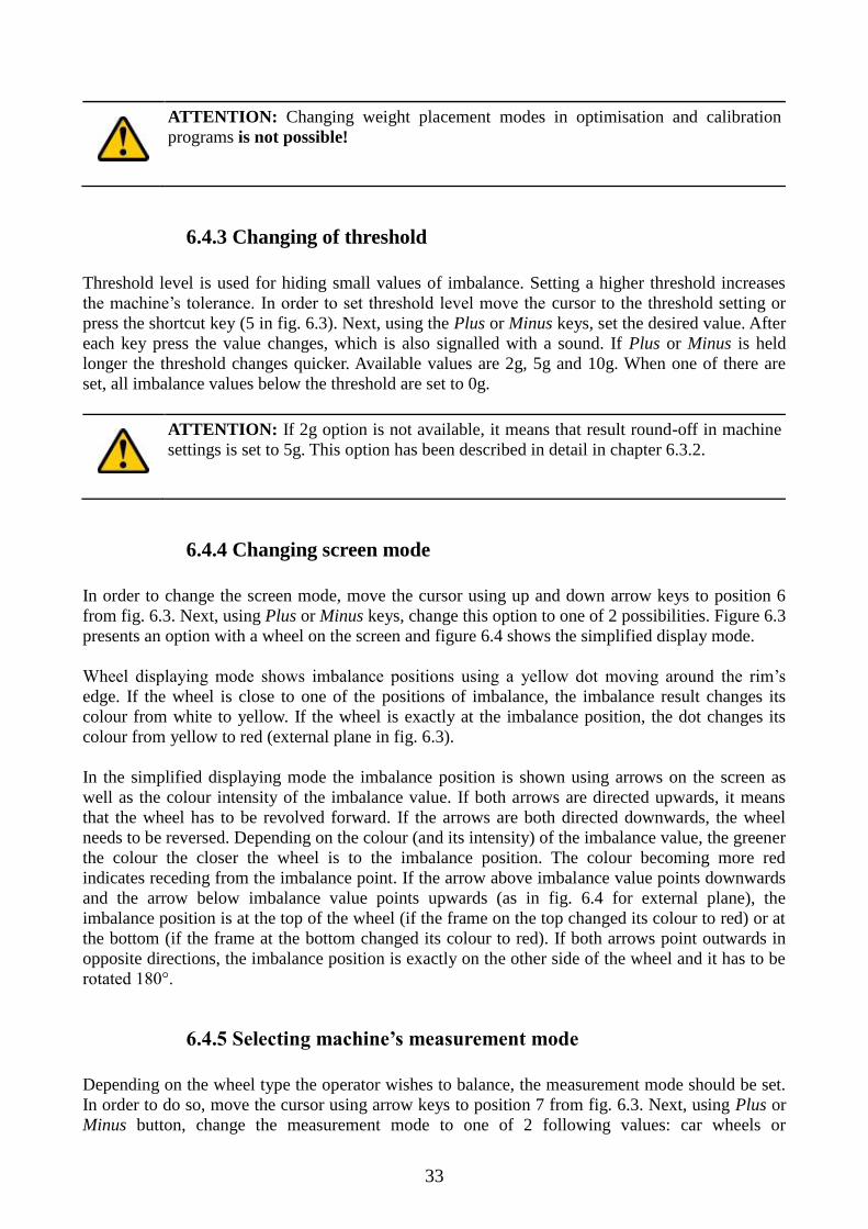
6.4.3 Changing of threshold
Threshold level is used for hiding small values of imbalance. Setting a higher threshold increases
the machine’s tolerance. In order to set threshold level move the cursor to the threshold setting or
press the shortcut key (5 in fig. 6.3). Next, using the Plus or Minus keys, set the desired value. After
each key press the value changes, which is also signalled with a sound. If Plus or Minus is held
longer the threshold changes quicker. Available values are 2g, 5g and 10g. When one of there are
set, all imbalance values below the threshold are set to 0g.
ATTENTION: If 2g option is not available, it means that result round-off in machine
settings is set to 5g. This option has been described in detail in chapter 6.3.2.
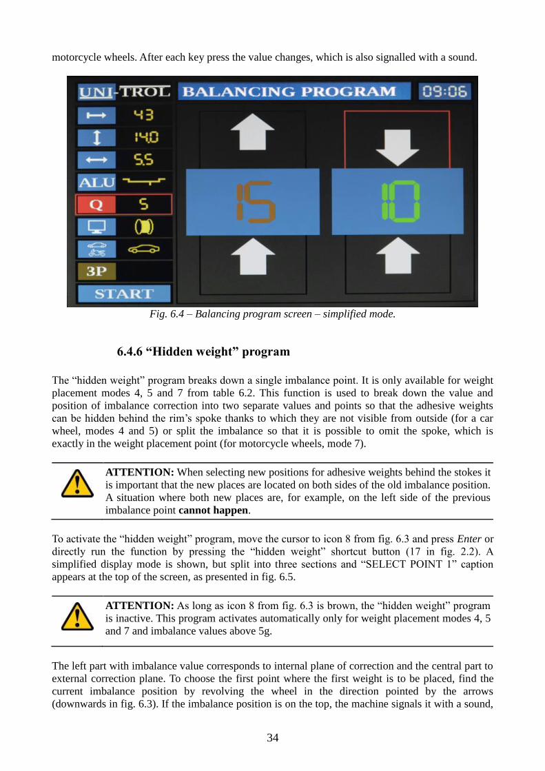
6.4.4 Changing screen mode
In order to change the screen mode, move the cursor using up and down arrow keys to position 6
from fig. 6.3. Next, using Plus or Minus keys, change this option to one of 2 possibilities. Figure 6.3
presents an option with a wheel on the screen and figure 6.4 shows the simplified display mode.
Wheel displaying mode shows imbalance positions using a yellow dot moving around the rim’s
edge. If the wheel is close to one of the positions of imbalance, the imbalance result changes its
colour from white to yellow. If the wheel is exactly at the imbalance position, the dot changes its
colour from yellow to red (external plane in fig. 6.3).
In the simplified displaying mode the imbalance position is shown using arrows on the screen as
well as the colour intensity of the imbalance value. If both arrows are directed upwards, it means
that the wheel has to be revolved forward. If the arrows are both directed downwards, the wheel
needs to be reversed. Depending on the colour (and its intensity) of the imbalance value, the greener
the colour the closer the wheel is to the imbalance position. The colour becoming more red
indicates receding from the imbalance point. If the arrow above imbalance value points downwards
and the arrow below imbalance value points upwards (as in fig. 6.4 for external plane), the
imbalance position is at the top of the wheel (if the frame on the top changed its colour to red) or at
the bottom (if the frame at the bottom changed its colour to red). If both arrows point outwards in
opposite directions, the imbalance position is exactly on the other side of the wheel and it has to be
rotated 180°.
6.4.5 Selecting machine’s measurement mode
Depending on the wheel type the operator wishes to balance, the measurement mode should be set.
In order to do so, move the cursor using arrow keys to position 7 from fig. 6.3. Next, using Plus or
Minus button, change the measurement mode to one of 2 following values: car wheels or
34
motorcycle wheels. After each key press the value changes, which is also signalled with a sound.
Fig. 6.4 – Balancing program screen – simplified mode.
6.4.6 “Hidden weight” program
The “hidden weight” program breaks down a single imbalance point. It is only available for weight
placement modes 4, 5 and 7 from table 6.2. This function is used to break down the value and
position of imbalance correction into two separate values and points so that the adhesive weights
can be hidden behind the rim’s spoke thanks to which they are not visible from outside (for a car
wheel, modes 4 and 5) or split the imbalance so that it is possible to omit the spoke, which is
exactly in the weight placement point (for motorcycle wheels, mode 7).
ATTENTION: When selecting new positions for adhesive weights behind the stokes it
is important that the new places are located on both sides of the old imbalance position.
A situation where both new places are, for example, on the left side of the previous
imbalance point cannot happen.
To activate the “hidden weight” program, move the cursor to icon 8 from fig. 6.3 and press Enter or
directly run the function by pressing the “hidden weight” shortcut button (17 in fig. 2.2). A
simplified display mode is shown, but split into three sections and “SELECT POINT 1” caption
appears at the top of the screen, as presented in fig. 6.5.
ATTENTION: As long as icon 8 from fig. 6.3 is brown, the “hidden weight” program
is inactive. This program activates automatically only for weight placement modes 4, 5
and 7 and imbalance values above 5g.
The left part with imbalance value corresponds to internal plane of correction and the central part to
external correction plane. To choose the first point where the first weight is to be placed, find the
current imbalance position by revolving the wheel in the direction pointed by the arrows
(downwards in fig. 6.3). If the imbalance position is on the top, the machine signals it with a sound,

35
arrows point inwards and the upper frame becomes red. At this point the machine shows the original
imbalance position.
Fig. 6.5 – Screen of “hidden weight” function – selecting the first point.
Having the imbalance position at the top, set the wheel so that one of the selected stokes (behind
which the new weight is to be placed) is at the top. If the stoke reaches the desired position, press
the Plus button.
ATTENTION: If after pressing the Plus key the machine gives a short signal and the
caption „SELECT POINT 1” blinks red, it means that the new weight place is too close
to the original imbalance correction point and the wheel should be turned a little more.
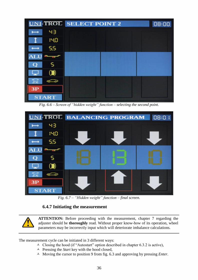
After approving of the first position (stoke), the caption on the top of the screen will change to
“SELECT POINT 2” and the imbalance values as well as arrows will disappear, as shown in
fig. 6.6. To select the second position, set the wheel so that the second stoke (placed on the other
side of the original imbalance position) is located at the top, and press the Plus key.
ATTENTION: If after pressing the Plus button the machine gives a short signal and
the caption “SELECT POINT 2” blinks red, it means that either the second position is
too close to the original imbalance position or the first selected point, or both selected
points are on the same side of the original imbalance position. In such case the second
point’s position should be changed.
After selecting the second point, three imbalance values are presented on the screen, just like in fig.
6.7. The left position contains the value for the internal imbalance correction plane and both the
central and right positions contain values of newly selected positions behind stokes (or omitting the
stoke for a motorcycle wheel). A weight should be placed on the rim for all of the correction planes,
after which a control measurement should be performed to check if the weights have been properly
placed and whether the wheel is balanced.
36
Fig. 6.6 – Screen of “hidden weight” function – selecting the second point.
Fig. 6.7 – “Hidden weight” function – final screen.
6.4.7 Initiating the measurement
ATTENTION: Before proceeding with the measurement, chapter 7 regarding the
adjuster should be thoroughly read. Without proper know-how of its operation, wheel
parameters may be incorrectly input which will deteriorate imbalance calculations.
The measurement cycle can be initiated in 3 different ways:
Closing the hood (if “Autostart” option described in chapter 6.3.2 is active),
Pressing the Start key with the hood closed,
Moving the cursor to position 9 from fig. 6.3 and approving by pressing Enter.

37
If the hood is not closed, the measurement will not start. After pressing the Start button with the
hood opened the machine will give an error (if lector option is available and activated it is a “close
hood” message, otherwise a short sound signal). After the measurement finishes, imbalance values
appear together with their positions where to place the weights. After placing the weights on the
rim, a control measurement should be performed to check whether the imbalances have been
cancelled out.
If after the control measurement it turns out that not all imbalance has been abolished (which can be
a result of poor quality weights or operator’s mistake), the machine will give hints – if lector is
available and activated – how to correct the position of the weight. If the lector option is not
available (or turned off), the correction should be performed according to the below described
scheme:
if the new imbalance position matches the first position or is only slightly shifted, the weight
should be increased (fig. 6.8a),
if the new imbalance position is on the other side of the first imbalance location or slightly
shifted from that location, the weight should be decreased (fig. 6.8b),
if the new imbalance position is to the left or right of the first imbalance location (fig. 6.8c
for left and fig. 6.8d for right), move the weight towards the new location, regardless of the
first position whether it is no the top or bottom of the wheel.
fig. 6.8 – Weight placement correction: 1: firstly placed weight
2: new imbalance location

38
6.4.8 Automatic wheel positioning
The moment when the measurement cycle is over, imbalance values are displayed and the wheel
stops rotating, the machine can automatically direct the wheel on one of the two imbalance
positions, depending on the operator’s choosing. The operator may look for a proper weight while
the balancer rotates the wheel to the specified plane’s imbalance location.
To start the automatic wheel positioning procedure to one of imbalance locations, the L or R key has
to be pressed for internal (left) or external (right) side of the wheel, respectively. In a short moment
the wheel will be positioned in the vicinity of the selected imbalance location.
ATTENTION: The automatic wheel positioning procedure can only be initiated when
the wheel fully stops. If the wheel is still in motion, buttons R and L are inactive. There
is also no possibility of changing a previously selected location during positioning.
6.5 Optimisation
Optimisation is a control test of a wheel providing rim and tyre alignment checking to ensure that
imbalances coming from both cancel each other out. It helps diminishing the imbalance of the
wheel and using smaller weights. Imbalances of both rim and tyre are performed in 2 measurement
cycles and the result takes both correction planes into account.
ATTENTION: Optimisation is to be performed as a preliminary operation to wheel
balancing using weights.
Fig. 6.9 – Optimisation screen – start-up.
To begin optimisation, go to the main menu (fig. 6.1) and select the Optimisation program if it has
not been activated yet. The screen presented in fig. 6.9 will appear on the display. Place just the
39
rim in the machine’s holder in a specific way, so that later it can be mounted exactly the same – e.g.
such that the valve is located at the same position as the markers on the spindle’s snug and on the
handle (3 in fig. 5.2).
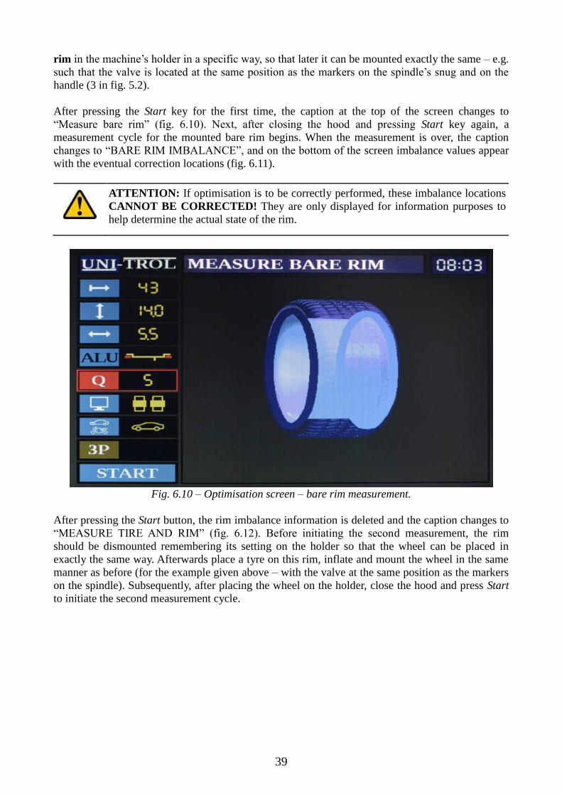
After pressing the Start key for the first time, the caption at the top of the screen changes to
“Measure bare rim” (fig. 6.10). Next, after closing the hood and pressing Start key again, a
measurement cycle for the mounted bare rim begins. When the measurement is over, the caption
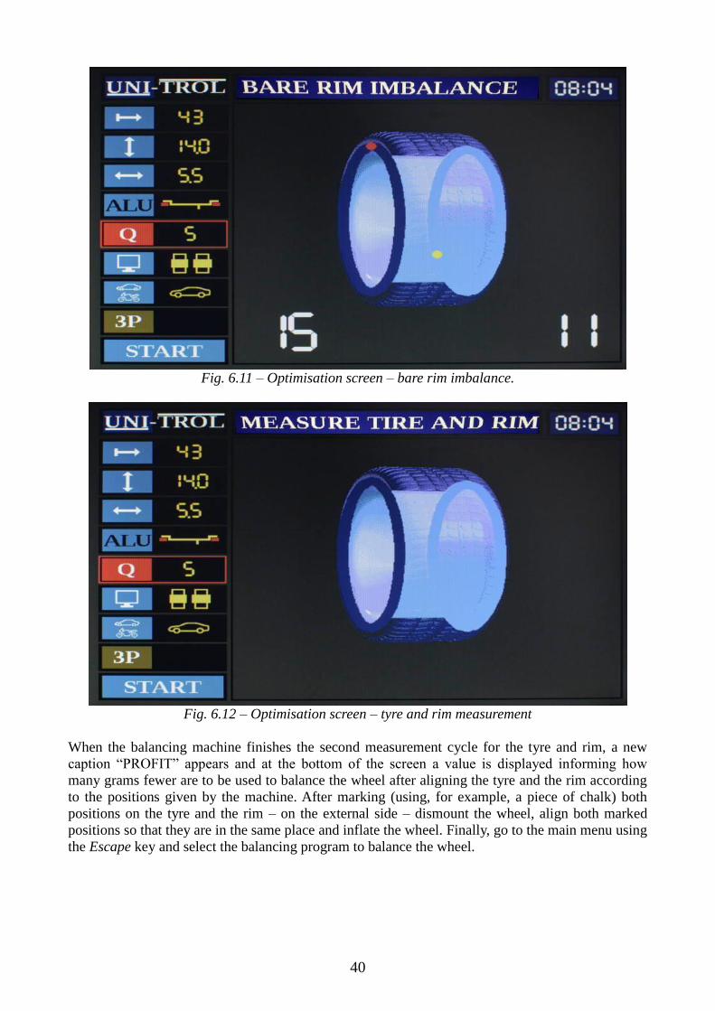
changes to “BARE RIM IMBALANCE”, and on the bottom of the screen imbalance values appear
with the eventual correction locations (fig. 6.11).
ATTENTION: If optimisation is to be correctly performed, these imbalance locations
CANNOT BE CORRECTED! They are only displayed for information purposes to
help determine the actual state of the rim.
Fig. 6.10 – Optimisation screen – bare rim measurement.
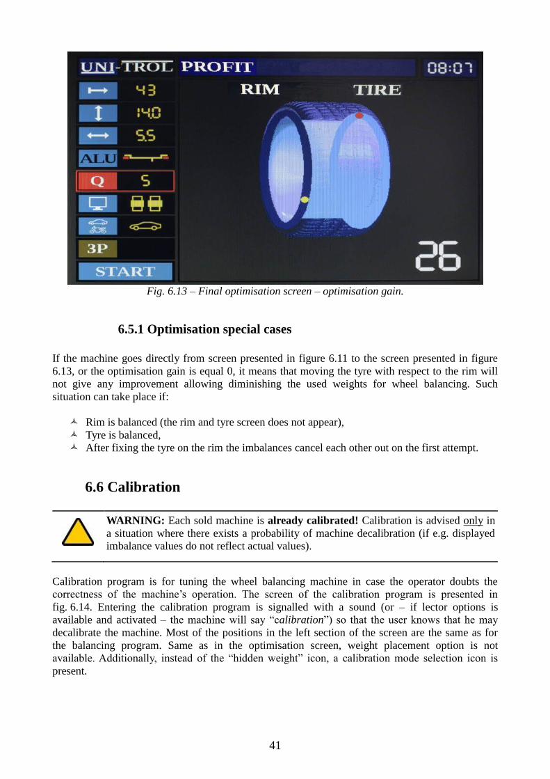
After pressing the Start button, the rim imbalance information is deleted and the caption changes to
“MEASURE TIRE AND RIM” (fig. 6.12). Before initiating the second measurement, the rim
should be dismounted remembering its setting on the holder so that the wheel can be placed in
exactly the same way. Afterwards place a tyre on this rim, inflate and mount the wheel in the same
manner as before (for the example given above – with the valve at the same position as the markers
on the spindle). Subsequently, after placing the wheel on the holder, close the hood and press Start
to initiate the second measurement cycle.
40
Fig. 6.11 – Optimisation screen – bare rim imbalance.
Fig. 6.12 – Optimisation screen – tyre and rim measurement
When the balancing machine finishes the second measurement cycle for the tyre and rim, a new
caption “PROFIT” appears and at the bottom of the screen a value is displayed informing how
many grams fewer are to be used to balance the wheel after aligning the tyre and the rim according
to the positions given by the machine. After marking (using, for example, a piece of chalk) both
positions on the tyre and the rim – on the external side – dismount the wheel, align both marked
positions so that they are in the same place and inflate the wheel. Finally, go to the main menu using
the Escape key and select the balancing program to balance the wheel.
41
Fig. 6.13 – Final optimisation screen – optimisation gain.
6.5.1 Optimisation special cases
If the machine goes directly from screen presented in figure 6.11 to the screen presented in figure
6.13, or the optimisation gain is equal 0, it means that moving the tyre with respect to the rim will
not give any improvement allowing diminishing the used weights for wheel balancing. Such
situation can take place if:
Rim is balanced (the rim and tyre screen does not appear),
Tyre is balanced,
After fixing the tyre on the rim the imbalances cancel each other out on the first attempt.
6.6 Calibration
WARNING: Each sold machine is already calibrated! Calibration is advised only in
a situation where there exists a probability of machine decalibration (if e.g. displayed
imbalance values do not reflect actual values).
Calibration program is for tuning the wheel balancing machine in case the operator doubts the
correctness of the machine’s operation. The screen of the calibration program is presented in
fig. 6.14. Entering the calibration program is signalled with a sound (or – if lector options is
available and activated – the machine will say “calibration”) so that the user knows that he may
decalibrate the machine. Most of the positions in the left section of the screen are the same as for
the balancing program. Same as in the optimisation screen, weight placement option is not
available. Additionally, instead of the “hidden weight” icon, a calibration mode selection icon is
present.

42
Fig. 6.14 – Calibration program screen
6.6.1 Calibration mode selection
All machines are equipped with a calibration device. It gives the operator an option to choose
between either calibrating with a wheel or the calibration device. In figure 6.14 one can see a new
icon in the “hidden weight” icon’s place: calibration mode selection. The currently displayed icon
shows the active calibration mode. Using the Plus or Minus button choose the desired option. If the
calibration device has been selected, there is no possibility of changing distance, diameter and width
parameters of the wheel, because these are permanently set for the device for best calibration
results.
6.6.2 Calibration using the device
After selecting calibration mode (chapter 6.6.1) put the calibration device on the car wheels’ holder,
close the hood and press Start. When imbalance values 0 for internal and 80 for external correction
planes appear, the machine is calibrated and ready to balance wheels.
WARNING: If the Start button is pressed after the calibration cycle is over, the
machine goes to the main menu screen to prevent decalibrating the machine by
mistake.
6.6.3 Calibration using a wheel
After selecting calibration mode (chapter 6.6.1), mount a BALANCED wheel (or with the least
possible imbalance) with known parameters. Hammer an 80g weight on the external correction
plane and set the real wheel parameters. Finally, close the hood and push the Start button. When
imbalance values 0 for internal and 80 for external correction planes appear, the machine is
calibrated and ready to balance wheels.

43
WARNING: If the Start button is pressed after the calibration cycle is over, the
machine goes to the main menu screen to prevent decalibrating the machine by
mistake.
ATTENTION: If the wheel used for calibration is not balanced, the machine will not
calibrate correctly. Even though it may seem that the cycle has successfully completed,
consecutive measurements will show that the obtained imbalance values differ from
the real ones.
6.6.4 Balancing a wheel before calibrating with it
To balance a wheel before using it for calibration go to the balancing program, set the threshold to
the lowest value and start a measurement. If there is no imbalance and two zeroes appear, the wheel
is balanced and may be used for calibrating the machine. Otherwise it should be balanced until
a control measurement shows zero-valued imbalance results. Only then calibration can be
performed as described in chapter 6.6.3.
44
7. Adjuster
ATTENTION: Measuring the diameter value with the adjuster gives true actual
values, which is why the value displayed on the screen may differ from the one marked
on the rim.
The adjuster is a tool for automatic distance and diameter parameter determination and also for
weight selection modes 4 and 5 from table 6.2 width of the wheel. Depending on whether the
weight selection mode has been selected prior to the adjuster measurement or not selected at all,
machine displays parameters in two ways. Both of them are correct. The distinction has been made
so that the operator can choose the most convenient method of parameter evaluation which suits
him best. All of it has been described below in chapters 7.1 and 7.2. Additionally, the machine is
capable of suggesting what weight placement mode to apply according to the way the balancing
machine’s operator uses the adjuster. It is described in detail in chapter 7.2.
WARNING: To start determining wheel parameters from the beginning, press the Stop
key. If the lector option is available and active, the machine signals it with a “Clear”
message.
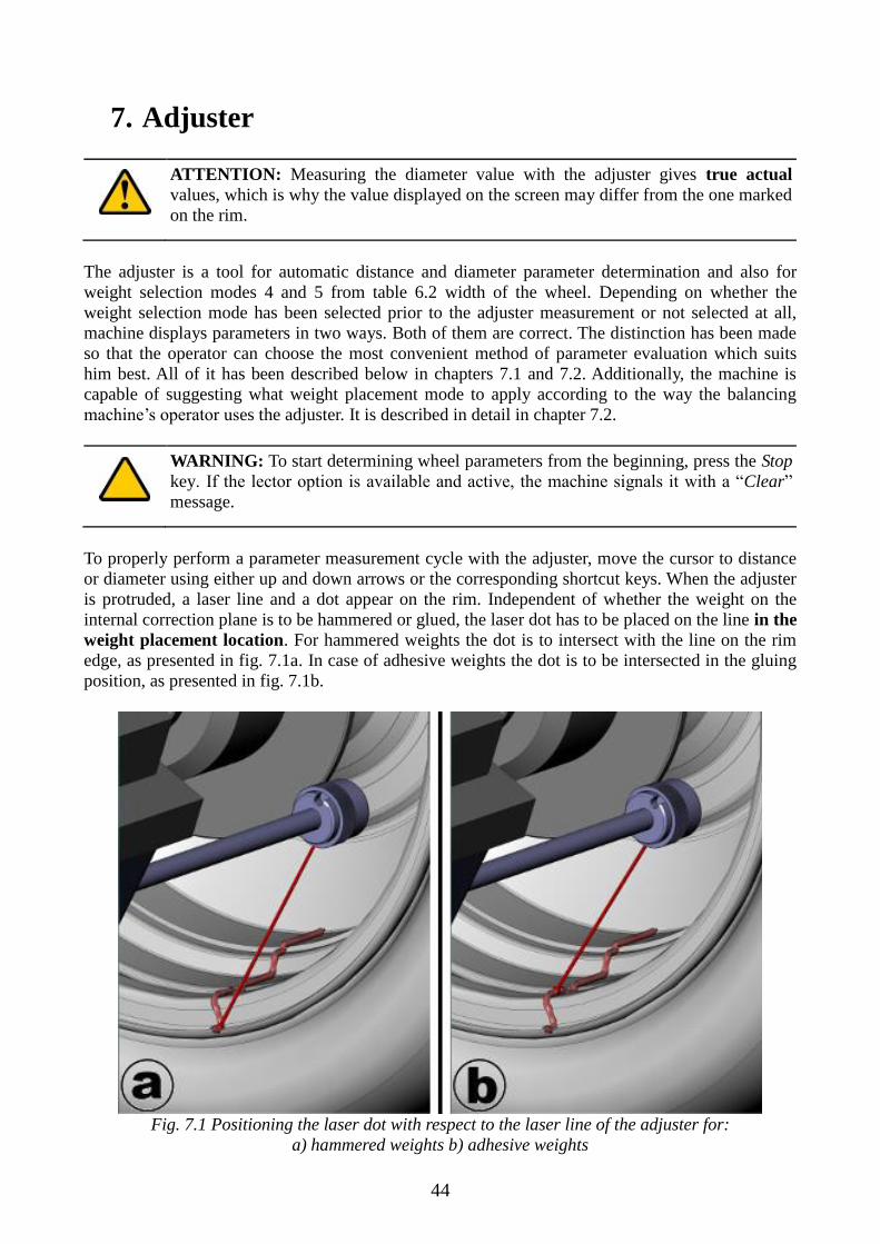
To properly perform a parameter measurement cycle with the adjuster, move the cursor to distance
or diameter using either up and down arrows or the corresponding shortcut keys. When the adjuster
is protruded, a laser line and a dot appear on the rim. Independent of whether the weight on the
internal correction plane is to be hammered or glued, the laser dot has to be placed on the line in the
weight placement location. For hammered weights the dot is to intersect with the line on the rim
edge, as presented in fig. 7.1a. In case of adhesive weights the dot is to be intersected in the gluing
position, as presented in fig. 7.1b.
Fig. 7.1 Positioning the laser dot with respect to the laser line of the adjuster for:
a) hammered weights b) adhesive weights

45
ATTENTION: For the motorcycle mode, the dot is always to be positioned on the line
like for adhesive weights (fig. 7.1b), regardless of whether weight placement mode 6 or
7 is selected. Weight position for mode 7 is evaluated according to input width
parameter and is always in the middle of the rim base.
ATTENTION: If it is impossible to measure distance from the machine to the wheel,
use a centimetre tape measure, subtract 2.5cm from the result, multiply by 4 and input
the result using Plus and Minus keys on the keyboard.
L = (x cm – 2.5cm)*4
7.1 Working with adjuster with weight placement mode selected
Selecting the weight placement mode has been described in chapter 6.4.2. If it is selected before
using the adjuster, the ALU caption on the icon (4 in fig. 6.3) changes its colour from white to black.
After moving the cursor to distance or diameter and drawing the adjuster out, both parameters
change their values according to the adjuster’s current laser dot position. For all weight placement
possibilities from table 6.2, weight placement position should be determined as described in the
beginning of chapter 7 and as illustrated in fig. 7.1. After setting the laser dot on the line in the
planned weight placement location the adjuster is to be left in such position for approximately
2 seconds until the machine generates a short signal indicating that the measurement result has been
saved. For weight placement modes 1, 2, 3, 6 and 7 put the adjuster back to its original position1.
The cursor will automatically relocate to the width icon, so the user can set this parameter before
starting the imbalance measurement. If the ultrasonic sensor is activated, it will measure the width
of the wheel during hood closing for the above mentioned weight placement modes.
For weight placement modes 4 and 5 from table 6.2 (adhesive weight placed inside the rim of a car
wheel), the ultrasonic sensor does not operate, because width is evaluated using the adjuster. The
adjuster has two modes of operation, which can be set in the machine settings section as described
in chapter 6.3.2:
Adjuster mode,
EASY mode.
Two methods have been provided for the convenience of the operator so that one can choose most
handy way to select weight position inside the rim – either using the laser dot and line or directly
under the handle’s disc.
7.1.1 Adjuster mode
In the Adjuster mode, the operator has the possibility to accurately point the adhesive weight
location inside the rim for external (right) correction plane. To indicate this point, right after the
machine saves the first adjuster measurement (as described in chapter 7.1) and signals it with a
short sound, one should without putting the adjuster back to its original position pull it out
further into the rim until the desired weight location is reached. Doing so invokes value changes to
diameter and width parameters with each adjuster position change. To correctly point the new
weight location inside the rim, move the adjuster so that the laser dot is at the very end where it is
still possible to glue the adhesive weight behind stokes. Subsequently, align the dot with the laser
1 If EASY mode is activated, the adjuster should be put to its original position after the first draw out for all
weight placement modes.

46
line and leave the adjuster in this position for approximately 2 seconds until the machine saves the
measurement, signalising it with a short sound. Finally, when the second phase of adjuster
measurement is over, put the adjuster back to its original position.
ATTENTION: While the adjuster performs the second measurement described above,
width of the wheel cannot be less than 2 inches. This is the reason width is displayed in
red when the value is below 2 inches and if the operator tries to save such value, the
machine generates an error signal and does not permit saving such result.
After completing the imbalance measurement and when the machine displays imbalance values, to
glue adhesive weights using the adjuster rotate the wheel so that the dot on the right side of the
wheel on the screen – for the wheel displaying mode – is at the bottom and changes its colour from
yellow to red, or – for the simplified displaying mode – both arrows point inwards on the imbalance
value and the bottom frame changes its colour from black to red. When the wheel is in the described
position, move the adjuster inside the wheel until the machine generates 5 short, quick signals and
on the screen – depending on the displaying mode – a second yellow frame appears around the red
frame for the simplified mode (fig. 7.2a), or a yellow frame around the imbalance value appears for
the wheel displaying mode (fig. 7.2b). Finally, position the laser dot on the line, clean the area
pointed by the dot and place an adhesive weight of appropriate value where the laser dot points.
Fig. 7.2 Part of the screen with the adjuster positioned in adhesive weight placement location
a: for simplified displaying mode b: for wheel displaying mode
7.1.2 EASY mode
EASY mode is an alternative for machine operators who do not want to operate the adjuster while
designating an adhesive weight location inside the wheel for external (right) correction plane. For
weight placement modes 4 and 5 from table 6.2, a caption titled “EASY” appears on the icon
(fig. 7.3) for pointing out that this option has been selected in the machine settings section. In this
operating mode, adhesive weights are placed UNDER THE HOLDER’S DISC, as presented in
fig. 7.4.

47
Fig. 7.3 EASY caption indicating the chosen adjuster operation mode
When using the adjuster, after the first measurement (distance and diameter) put it back to its
original position. The machine calculates width between both weights (for left and right planes) of
the balanced wheel automatically due to the fact that the weight is glued under the holder’s disc.
After completing the imbalance measurement and when the machine displays imbalance values, to
glue adhesive weights using the adjuster rotate the wheel so that the dot on the right side of the
wheel on the screen – for the wheel displaying mode – is at the bottom and changes its colour from
yellow to red, as presented in fig. 7.5a, or – for the simplified displaying mode – both arrows point
inwards on the imbalance value and the bottom frame changes its colour from black to red, as
shown in fig. 7.5b. When the balanced wheel is positioned in described manner, clean the area
under the holder’s disc and place an adhesive weight of appropriate value like presented in fig. 7.4.
Fig. 7.4 Weight placement location for adjuster’s EASY mode.
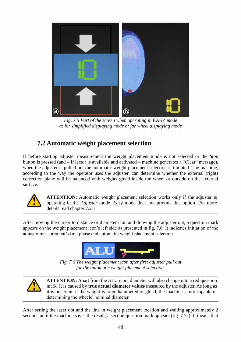
48
Fig. 7.5 Part of the screen when operating in EASY mode
a: for simplified displaying mode b: for wheel displaying mode
7.2 Automatic weight placement selection
If before starting adjuster measurement the weight placement mode is not selected or the Stop
button is pressed (and – if lector is available and activated – machine generates a “Clear” message),
when the adjuster is pulled out the automatic weight placement selection is initiated. The machine,
according to the way the operator uses the adjuster, can determine whether the external (right)
correction plane will be balanced with weights glued inside the wheel or outside on the external
surface.
ATTENTION: Automatic weight placement selection works only if the adjuster is
operating in the Adjuster mode. Easy mode does not provide this option. For more
details read chapter 7.2.1.
After moving the cursor to distance or diameter icon and drawing the adjuster out, a question mark
appears on the weight placement icon’s left side as presented in fig. 7.6. It indicates initiation of the
adjuster measurement’s first phase and automatic weight placement selection.
Fig. 7.6 The weight placement icon after first adjuster pull out
for the automatic weight placement selection.
ATTENTION: Apart from the ALU icon, diameter will also change into a red question
mark. It is caused by true actual diameter values measured by the adjuster. As long as
it is uncertain if the weight is to be hammered or glued, the machine is not capable of
determining the wheels’ nominal diameter.
After setting the laser dot and the line in weight placement location and waiting approximately 2
seconds until the machine saves the result, a second question mark appears (fig. 7.7a). It means that

49
the second phase of adjuster measurement has started, which defines the location of the weight for
the external (right) imbalance correction plane. If the weight is to be placed on the outer part of the
rim and not inside, the adjuster should be put back in its original position. Afterwards, the cursor
will be relocated to the weight placement icon and the machine will suggest the first mode from
table 6.2.
WARNING: Due to selecting the weight location on the outer side of the wheel, there
is no possibility to change to weight placement modes with the weight inside the rim
for the external (right) correction plane. Only modes 1, 2 and 3 from table 6.2 are
available. To change it and have the ability to select any weight placement mode, press
the Stop key in order to clear saved results. If the lector option is available and
activated, the machine will generate a “Clear” message.
If the weight is to be placed inside the rim, then after the first phase move the adjuster inside the
rim. This will relocate the question mark in the weight placement icon to the left (fig. 7.7b), and the
width parameter will start changing with further adjuster movement into the rim. After aligning the
laser dot with the laser line in the desired weight location, wait approximately 2 seconds for the
machine to save the result. After putting the adjuster back to its original position, the cursor will be
relocated to the weight placement icon and the machine will suggest mode 4 from table 6.2.
a b
Fig. 7.7 Weight placement icon view a: beginning of second phase
b: when continuing adjuster movement into the rim.
WARNING: Due to selecting the weight location inside the wheel, there is no
possibility to change to weight placement modes with the weight on the outer side.
Only modes 4 and 5 from table 6.2 are available. To change it and have the ability to
select any weight placement mode, press the Stop key in order to clear saved results. If
the lector option is available and activated, the machine will generate a “Clear”
message.
7.2.1 EASY mode and automatic weight placement selection
If EASY mode is activated, automatic weight placement selection does not function. It is caused by
automatic width calculation when the weight is placed under the holder’s disc. That is why there is
no need to insert the adjuster inside the rim for the second time.
When the first phase of adjuster measurement is initiated, 3 question marks are displayed on the
weight placement icon as presented in fig. 7.8. After determining weight placement for the internal
(left) imbalance correction plane (described in the beginning of chapter 7) and saving the result,
adjuster is to be put back to its original position. Afterwards, the cursor is automatically placed on
the weight placement icon. To select the desired mode, use the Plus or Minus key.
Fig. 7.8 Weight placement icon view after pulling the adjuster out in EASY mode.

50
8. User memory
Wheel balancing machines are equipped with internal memory allowing operators to save four
different wheel parameters. To read previously saved or save current wheel parameters in one of the
memory banks, press the Memory button (18 in fig. 2.2) in the balancing program screen. A new
screen, presented in fig. 8.1, will appear on the LCD display. Each of the four memory banks has its
own name, limited to 14 characters, which can be changed according to the operator’s need.
Fig. 8.1 User memory screen.
Each memory bank has its submenu, which is activated by moving the cursor to one of the banks
and pressing the Enter key. Right above the first memory bank a small menu appears, presented in
fig. 8.2. It is used for either reading memory, saving to memory or editing the memory bank’s name.
Fig. 8.2 Memory bank’s submenu
8.1 Memory reading
To read previously saved wheel parameters select the desired memory bank and press Enter to
activate the submenu. Afterwards, move the cursor to the Read position using either the up and
down arrow keys or L and R keys (if the cursor’s position has not been changed, it is by default set
to “Read”). After confirming with the Enter key, the machine brings the balancing program screen
back with all the parameters set to values read out from the selected memory bank. If the lector
option is available and activated, the machine signalises the reading with a “Memory reading”
message.

51
WARNING: Memory reading is an irreversible operation! It replaces previous
parameters and there is no possibility of recovering these parameters other than
inputting them again.
8.2 Saving to memory
To save newly provided wheel parameters select the desired memory bank, which can have its data
replaced, and press Enter. Afterwards, move the cursor to the Save position using either the up and
down arrow keys or L and R keys and press Enter again to approve the option. The machine brings
the balancing program screen back. If the lector option is available and activated, the machine
signalises the reading with a “Memory record” message.
8.3 Editing the memory bank name
By default, all banks have the same name followed by a different number from 1 to 4. For the
operator’s convenience, there is a possibility of changing the name of each memory bank for easier
distinction between them. To do so, select the desired memory bank and press Enter to activate the
submenu. Afterwards, move the cursor to the Edit position using either the up and down arrow keys
or L and R keys and press Enter again. At that moment the menu element becomes divided into 14
elements, each representing a single character. To move the blue cursor, set on the first element by
default, use the L and R keys to shift the cursor left or right, respectively. To change a character
simply use the Plus and Minus keys. To clear the field (and insert a “space”) press the Stop button.
If the new name is ready, press the Memory key to approve of the performed changes or press
Escape to cancel them. After entering the editing mode, a small description of above described
keys’ function is presented for the operator.

52
9. Diagnostics and fault detection
FAILURE POSSIBLE CAUSES SOLUTION
The balancing machine
does not generate sounds,
the power button is not lit,
the monitor does not work
Electric system failure – no electric
supply
Check the fuse, check if all
electrical connections are not
worn out
Unstable, incorrect results
of the adjuster
measurement
The photo coupler’s controller plate
is damaged, broken pieces on code
bar, damaged potentiometer
Blow the photo couplers with
dry air, change the code bar,
change the potentiometer
The keyboard's buttons do
not activate all functions
Poor contact of wires connecting the
keyboard to the indicator's plate and
indicator's plate to the main board,
damaged keyboard
Check all connections, replace
the keyboard
Incorrect indications for
different wheel mountings
The spindle and/or the cone are dirty,
the centralizing cone is worn out, the
nut is broken, the holder is broken or
hit
Clean all dirty elements,
replace the cone, replace the
nut, replace the holder
Contacting our authorised service is always advised.

53
UNI -TROL UNI - TROL Co. Ltd.
MANUFACTURING PLANT & STORE ul . Estrady 56 , 01 - 932 Warsaw, POLAND tel.(+4822) 8179422 or 8349013 or 8349014 int. 117
http://www.unitrol.com.pl. fax(+4822) 8179422 or 8349013 or
8349014 int. 115
e-mail: [email protected] ; [email protected] ;
WHEEL BALANCING MACHINES RIM STRAIGHTENING MACHINES TYRE CHANGERS EQUIPMENT FOR TYRESHOPS
Statistic no. : 008132994 EC VAT no. : PL5270205246 Register no. : KRS 0000111731 EORI no. : PL527020524600000 Account : for EURO : BZ WBK SA no. PL 62 1090 1014 0000 0000 0303 1619 (swift code: WBK PPL PP XXX)
CE Conformity Declaration in accordance with directives : 2006/42/EC, 2006/95/EC, 2004/108/EC
We : Uni-trol Co. Ltd. Ul. Estrady 56 01-932 Warsaw Poland declare, under our exclusive responsibility, that the product
Wheel balancing machine
Electromechanical device
model TROLL 2356LP
Serial number ..............................................,
concerned by this declaration, complies with all relevant requirements of the Machinery Directive:
- Directive 2006/42/EC (safety machines), applicable in the essential requirements and relevant conformity assessment procedures, as well as on the essential requirements of the following directives:
- Directive 2006/95/EC (the low voltage ); - Directive 2004/108/EC (the electromagnetic compatibility).
In order to verification of compliance with the applicable legal regulations have been consulted harmonized standards and other normative documents:
PN-EN ISO 12100:2012P Safety of machinery -- General principles for design – Risk assessment and risk reduction
PN-EN 61000-6-3:2008P
Electromagnetic compatibility (EMC) -- Part 6-3: General standards -- Emission standard for environments: residential, commercial and light industrial

54
PN-EN 61000-6-4:2008P
Electromagnetic compatibility (EMC) -- Part 6-4: General standards -- Emission standard for industrial environments
PN-EN ISO 13857:2010P
Safety of machinery - Safety distances to prevent hazard zones being reached by upper and lower limbs
PN-EN 349+A1:2010P
Safety of machinery - Minimum gaps to avoid crushing of parts of the human body
PN-EN 60204-1:2010P
Safety of machinery -- Electrical equipment of machines -- Part 1: General requirements
PN-EN 61293:2000P
Marking of electrical equipment with ratings related to electrical supply -- Safety requirements
PN-EN ISO 11554:2010P
Optics and photonics - Lasers and laser-related equipment - Test methods for laser beam power, energy and temporal characteristics
PN-EN 60825-12:2008P Safety of laser products - Part 12: Safety of free space optical communication systems used for transmission of information
PN-EN ISO 11201:2012P
Acoustics -- Noise emitted by machinery and equipment -- Determination of emission sound pressure levels at a work station and at other specified positions in an essentially free field over a reflecting plane with negligible environmental corrections PN-EN ISO11202:2012P Acoustics -- Noise emitted by machinery and equipment -- Determination of emission sound pressure levels at a work station and at other specified positions applying approximate environmental corrections PN-EN ISO 4871:2012P Acoustics -- Declaration and verification of noise emission values of machinery and equipment
PN-EN 50419:2008P
Marking of electrical and electronic equipment in accordance with Article 11 (2) of Directive 2002/96/CE (WEEE)
PN-EN 61190-1-3:2008E
Materials for connecting electronic components -- Part 1-3: Particular requirements for solders for electronic applications and solders with fluxes or without fluxes for soldering electronic components .
PN-EN 61760-1:2006E
Surface mounting technology -- Part 1: Method qualification standard components for surface mount (SMD) (SMD)
The technical documentation of this device, referred to in point 1 of Annex VII A of the Machinery Directive, is located in the headquarters Uni-trol Ltd. (address as above) and will be made available to the competent national authorities for at least 10 years after the last piece.
The person responsible for the preparation of the technical documentation of the product and introducing changes in it, is MSc. Gregory Tworek - Member of the Board.
This EC Declaration of Conformity will be kept by the manufacturer of the product for 10 years from the date of produce the last unit and will available for market supervisory authorities for verification.
MSc. Gregory Tworek - Member of the Board.
Warsaw, 21.10.2013
..................................................... Signature