wheelchair control by head motion - doiserbia · wheelchair control by head motion ... project a...
TRANSCRIPT
SERBIAN JOURNAL OF ELECTRICAL ENGINEERING
Vol. 10, No. 1, February 2013, 135-151
135
Wheelchair Control by Head Motion
Aleksandar Pajkanović1, Branko Dokić
1
Abstract: Electric wheelchairs are designed to aid paraplegics. Unfortunately,
these can not be used by persons with higher degree of impairment, such as
quadriplegics, i.e. persons that, due to age or illness, can not move any of the
body parts, except of the head. Medical devices designed to help them are very
complicated, rare and expensive. In this paper a microcontroller system that
enables standard electric wheelchair control by head motion is presented. The
system comprises electronic and mechanic components. A novel head motion
recognition technique based on accelerometer data processing is designed. The
wheelchair joystick is controlled by the system’s mechanical actuator. The
system can be used with several different types of standard electric wheelchairs.
It is tested and verified through an experiment performed within this paper.
Keywords: Medical devices, Motion recognition, Inertial sensors, Wheelchair,
Quadriplegia, Novel algorithm.
1 Introduction
Quadriplegics are persons who are not able to use any of the extremities.
The reasons for such decreased motion possibilities can be different: stroke,
arthritis, high blood pressure, degenerative diseases of bones and joints and
cases of paralysis and birth defects. Also, quadriplegia appears as a
consequence of accidents or age. The patients with such severe disabilities are
not able to perform their everyday actions, such as: feeding, toilette usage and
movement through space. Depending on the severity of the disability, a patient
can retain freedom of movement to a certain level by using different medical
devices [1].
There are two types of medical devices that enable independent movement
to a person suffering from paraplegia. Those are exoscelets and wheelchairs.
Both of these contain electronic systems to enable and improve person’s
movement ability both in outdoor and indoor conditions. Electronic systems,
such as sensors, actuators, communication modules and signal processing units,
are used to recognize the activity that the patient is trying to perform and help
him carry it out in coordination with the commands given. The application of
the two mentioned devices is different. Exoscelets must provide body support,
1University of Banja Luka, Faculty of Electrical Engineering, Patre 5, 78 000 Banja Luka, The Republic of Srpska, Bosnia and Herzegovina; E-mails: [email protected], [email protected]
UDK: 615.478.3:681.586 DOI: 10.2298/SJEE1301135P
A. Pajkanović, Branko Dokić
136
which makes them more complex. Also, an error in patient’s command
recognizing process can lead to very serious consequences – fall and,
eventually, injury.
Wheelchair operation is based on navigation, which, in this case, is defined as safe transport from the starting point to a given destination. The wheelchair, comparing to the exoscelet, are a more general medical device and a much simpler one. Thus, the wheelchairs are used more often [1]. Nevertheless, only patients with healthy upper extremities (paraplegics) can successfully operate standard electric wheelchairs. The patients who cannot use any of their extremities (quadriplegics) cannot operate these [2].
In such cases, when the patient is not able to use the standard control interface, other approaches are used. Through numerous research projects in this area, several different solutions have been developed, such as: SENARIO [3], VAHM [4], Rolland [5], SIAMO [6], Wheelesley [7], and omniwheeled platform [8]. Electronic systems in common for all these projects are sensors, signal processing units, software that translates user’s commands into medical device actions. These solutions are dubbed robotic wheelchair. User can control the device via touchscreens [9 – 10] and voice commands [11]. Besides these, wheelchair control is also possible by eye movement and electromiographic sensors. Such interfaces are Telethesis [12] and EagleEyes [13]. Detailed overview of these researches can be found in [1]. For human-machine interaction human motion recognition is also used [14 – 20].
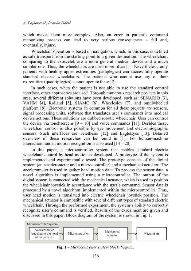
In this paper, a microcontroller system that enables standard electric wheelchair control by head motion is developed. A prototype of the system is implemented and experimentally tested. The prototype consists of the digital system (an accelerometer and a microcontroller) and a mechanical actuator. The accelerometer is used to gather head motion data. To process the sensor data, a novel algorithm is implemented using a microcontroller. The output of the digital system is connected with the mechanical actuator, which is used to position the wheelchair joystick in accordance with the user’s command. Sensor data is processed by a novel algorithm, implemented within the microcontroller. Thus, user head motion is translated into electric wheelchair joystick position. The mechanical actuator is compatible with several different types of standard electric wheelchair. Through the performed experiment, the system’s ability to correctly recognize user’s command is verified. Results of the experiment are given and discussed in this paper. Block diagram of the system is shown in Fig. 1.
Fig. 1 – Microcontroller system block diagram.
Wheelchair Control by Head Motion
137
The rest of this paper is organized as follows. In Section 2, an overview of the robotic wheelchair is given. Some of the solutions developed in the last two decades are described. In Section 3, a short introduction to motion recognition research field is given. The mentioned novel algorithm used to process the head motion data obtained using the accelerometer is described in Section 4. The operation steps are explained in detail. In Section 5, the hardware implemen-tation of the system prototype is discussed. The performed experiment is explained and the results yielded are shown and discussed in Section 6.
2 Robotic Wheelchair Overview
Within SENARIO [3] project a wheelchair intelligent navigation system is developed. In this case, robotic wheelchair provides two modes of operation: automatic and semiautomatic. While in automatic mode, the interface accepts user’s commands. Upon command reception, the wheelchair defines its current position and the destination position. Then, the route from the starting point to a destination is defined. The wheelchair follows this route until the command is successfully performed. While moving according to the route, the wheelchair avoids obstacles, using the environment information gathered through ultrasound and infrared sensors. When in semiautomatic mode, user can interfere with the performance of the activity that the wheelchair defined according to the previous user’s command. In this mode, the user can directly navigate the wheelchair over a specific route.
VAHM [4] project yielded autonomous wheelchair to provide independent movement to patients that are not able to control standard electric wheelchair. Software architecture is divided in three levels: physical, local and global. Human-machine interface is used to interpret user commands. The local level implements detection of walls and other obstacles. The global level enables route or object following, movement control, obstacle avoidance and route planning.
The result of the project titled Bremen Autonomous Wheelchair is the robotic wheelchair Rolland [5]. This wheelchair is developed so that the help of rout planning devices is used. It is characterized by fine tuning of the movement speed and automatic passing through door.
Electronic system to navigate electric wheelchair is also developed within the SIAMO [6] project. In this case, basic characteristics are: novel human-machine interface, ultrasound, infrared and video sensors, and advanced control and navigation systems. The user can give commands to this robotic wheelchair by face expressions.
Wheelesley [7] is developed as a general purpose medical device. As such, the wheelchair offers several different operation modes. Each of these modes gives the user different privileges while operating the wheelchair. Namely, the
A. Pajkanović, Branko Dokić
138
wheelchair can be controlled by joystick (where the function of every joystick movement can be redefined), by several mechanical switches (the combination of which represents a predefined command) and by blowing tube (where the detection of air speed is enabled). The tube is used only in the worst cases. The wheelchair is capable of avoiding obstacles and automatic passing through doors. In order to accomplish this, the information gathered through existing set of ultrasound and infrared sensors are used.
Usual electric wheelchair design is based on motorizing two wheels of the four. Besides this approach platforms with different number of wheels can be used. Such solution is the omniwheeled platform developed in [8]. The authors have shown that such robotic wheelchair move with ease through narrow passages. It is characterized by obstacle detection sensors and the control system based on fuzzy logic.
3 Motion Recognition
Motion recognition is a process in which a receiver recognizes user’s motion. In this context, motions are expressional movements of human body parts, such as: fingers, hands, arms, head, face, legs. The purpose of these movements can be information transfer or the interaction with the environ-ments. Motion recognition is applicable in various fields: enabling children to interact with a computer, understanding sign language, medical devices development, navigation and manipulation of the virtual environment, tracking psychophysical condition of the driver in order to reduce the number of accidents, lie detection, etc. [15]. There are many different motion recognition approaches, of which the most common are based on hidden Markov models [16] and based on artificial intelligence (fuzzy logic and neural networks) [17]. Besides in theoretical approach, motion recognition techniques also differ in devices used for implementation. Namely, in order to recognize significant motions, the information on these motions must be known at all times. In order to acquire these informations different recording systems are used. Standard input devices, such as keyboard or mouse are not suitable for this kind of human-machine interaction. Thus, the devices that record position and attitude of human body parts, skin susceptibility, face expressions and so on, are used [15].
Motion recognition is a very intuitive way to interact with electronic devices, but there are technical difficulties. First of all, there is no standardized library in the field of motion recognition. Thus, in most cases the user has to define a personal motion library, the library of personalized motions. When using personalized motions, it is very hard to gather a large set of sample moves, needed for statistic methods application, such as hidden Markov models. A difficulty is also a fact that the recognition has to be done online (immediately) in order for such interaction to make sense. This fact affects the resources of the receiver – its characteristics have to be considered, such as
Wheelchair Control by Head Motion
139
processing power and, consequently, battery capacity. The most common motion recognition approach is based on computer vision techniques. These techniques are limited by their hardware (the cameras are necessary) and high processing power requirements (video processing). Inertial sensors, characterized by low power and low prices, have become available in recent years. Besides these two positive properties, they are also characterized by very small dimensions. These characteristics qualifie them to be used in motion recognition field. There are several different approaches to motion recognition by inertial sensors [18 – 20]. Besides stand alone sensors, other devices can also be used, such as cell phones [18] and game controllers [20].
4 Head Motion Recognition Algorithm
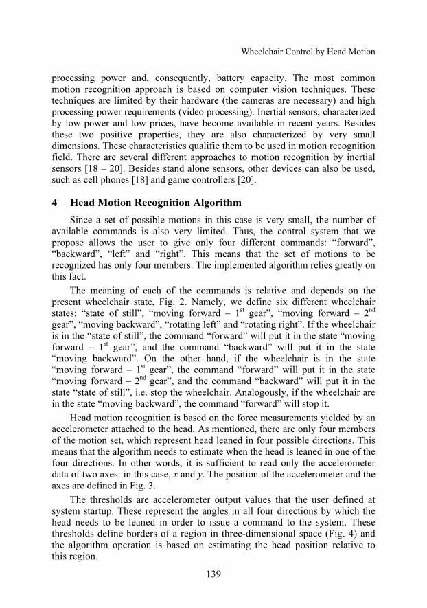
Since a set of possible motions in this case is very small, the number of available commands is also very limited. Thus, the control system that we propose allows the user to give only four different commands: “forward”, “backward”, “left” and “right”. This means that the set of motions to be recognized has only four members. The implemented algorithm relies greatly on this fact.
The meaning of each of the commands is relative and depends on the present wheelchair state, Fig. 2. Namely, we define six different wheelchair states: “state of still”, “moving forward – 1
st gear”, “moving forward – 2
nd
gear”, “moving backward”, “rotating left” and “rotating right”. If the wheelchair is in the “state of still”, the command “forward” will put it in the state “moving forward – 1
st gear”, and the command “backward” will put it in the state
“moving backward”. On the other hand, if the wheelchair is in the state “moving forward – 1
st gear”, the command “forward” will put it in the state
“moving forward – 2nd gear”, and the command “backward” will put it in the
state “state of still”, i.e. stop the wheelchair. Analogously, if the wheelchair are in the state “moving backward”, the command “forward” will stop it.
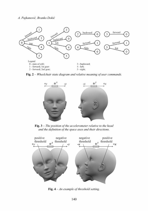
Head motion recognition is based on the force measurements yielded by an accelerometer attached to the head. As mentioned, there are only four members of the motion set, which represent head leaned in four possible directions. This means that the algorithm needs to estimate when the head is leaned in one of the four directions. In other words, it is sufficient to read only the accelerometer data of two axes: in this case, x and y. The position of the accelerometer and the axes are defined in Fig. 3.
The thresholds are accelerometer output values that the user defined at system startup. These represent the angles in all four directions by which the head needs to be leaned in order to issue a command to the system. These thresholds define borders of a region in three-dimensional space (Fig. 4) and the algorithm operation is based on estimating the head position relative to this region.
A. Pajkanović, Branko Dokić
140
Fig. 2 – Wheelchair state diagram and relative meaning of user commands.
Fig. 3 – The position of the accelerometer relative to the head
and the definition of the space axes and their directions.
Fig. 4 – An example of threshold setting.
Wheelchair Control by Head Motion
141
The algorithm is implemented through several steps of operation. The
motion data processing is done online, i.e. the command is estimated while the
user moves the head. The algorithm description that follows assumes that
microcontroller has read the current result of the accelerometer measurements.
In the following paragraphs, the algorithm operation is described.
Eliminating gravity component. When in gravitational field, the accelero-
meter shows acceleration of the Earth’s gravity (except if it is in free fall). Thus,
in order to get the actual state of the accelerometer, gravitational component has
to be removed. In this case, this is done in two steps. First, on startup, the
gravity is measured. Because of this, it is required that the patient remains calm
for the first period after turning on the system. The end of this period is
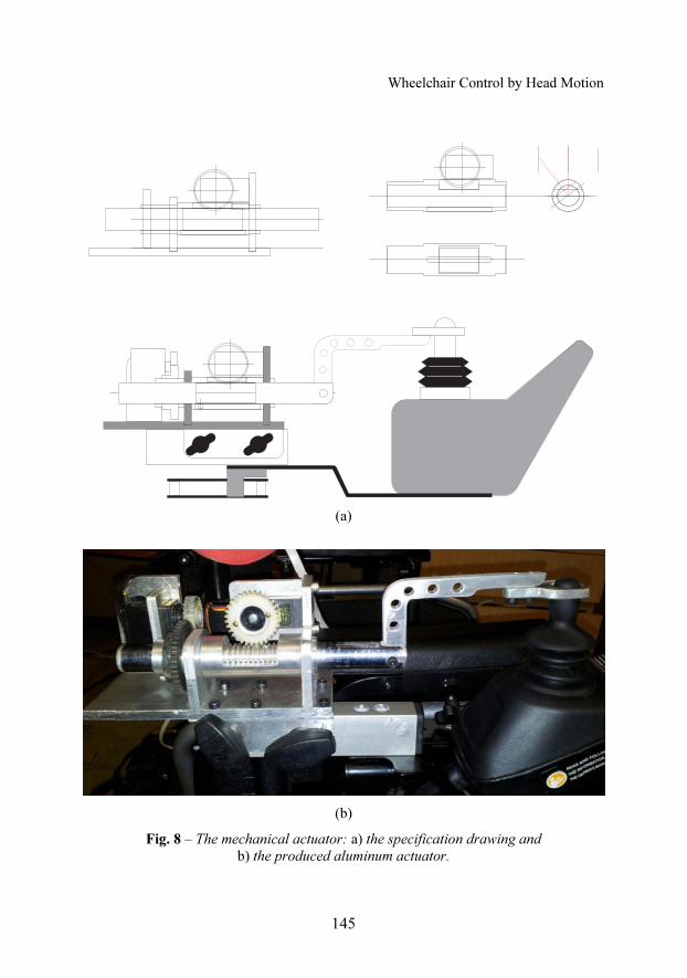
signalized by the diode B5 (Fig. 9). Then, after every measurement, that amount
is subtracted from the accelerometer output signal. Thus, the gravitational
component of acceleration is eliminated in correspondence the position and
attitude of the control unit attached to the patient’s head.
Reading and filtering of the accelerometer output. Output voltage changes,
which appear as a result of head motion not intended to issue a command lead
to errors. Namely, the system can wrongly recognize and start executing an
unwanted command. Such changes are sudden, so they can be removed using a
low-pass filter. In this case, the filter is software implemented to remove the
high frequency changes in the accelerometer signal.
Threshold setting. Since this is a system intended for patients with severe
disabilities, it has to be as adjustable as possible. Because of this, the threshold
setting according to patient’s possibilities is enabled. The thresholds are set up
upon start-up. After corresponding signalization, the patient moves the head
first in +x direction, and then in +y direction. Axes and directions are defined
relative to the position and attitude of the control unit attached to the head of the
patient. In Fig. 3, the axes and directions are shown. As it can be seen, the x axis
change resembles the head movement forward-backward and the y axis change
resembles the head movement left-right. In this context, positive movements are
backward and right, respectively. In Fig. 4, an example of threshold setting is
shown. This operation can be done during system operation. The threshold
setting operation is started by pressing the C0 pushbutton (Fig. 9) and holding it
until the patient moves the head in the corresponding position, relative to the +x
axis. When the button is released, the system memorizes the threshold and turns
on the B6 (Fig. 9) diode. This means that the procedure for setting the +y axis
threshold can commence. Now, the pushbutton C1 (Fig. 9) needs to be pressed
and held until the patient moves the head in the corresponding position, relative
to the +y axis.
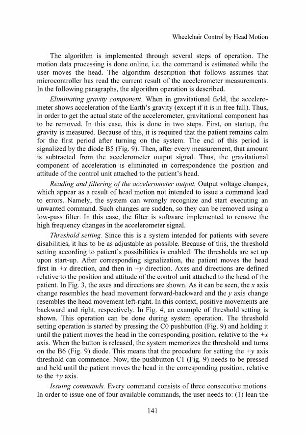
Issuing commands. Every command consists of three consecutive motions.
In order to issue one of four available commands, the user needs to: (1) lean the
A. Pajkanović, Branko Dokić
142
head over a threshold; (2) return the head to the starting position; (3) repeat the
movement (1). In order to be able to issue the next command, the user needs to
make the fourth motion, which is not part of the actual command. Namely, after
(3) the user needs to return the head in the starting position. An example of
issuing a command is shown in Fig. 5. The other commands are issued
analogously.
Fig. 5 – An example of issuing a command – “forward”.
Fig. 6. – Accelerometer x axis data while issuing the command “forward”.
These motions need to be performed within a time frame. In this example,
the time interval is 2 s. Namely, if the user leans the head forward (in order to,
for example, read) the system will recognize the motion (1) of the command
“forward”. Nevertheless, if the user remains in that position longer than two
seconds, the motion (1) is neglected, and the system waits for the next motion of
Wheelchair Control by Head Motion
143
interest. In Fig. 6 the output signal of the accelerometer x axis is shown when
the user issues the command “forward”. The values of the starting position and
the threshold are marked, as are all motion of which the command comprises.
Light signalization. In order to make the system more user friendly, enable
faster learning and understanding of the system, LED indication is implemented
(turning of and on of the B7 diode, Fig. 9). The system informs the user on its
current state through LED signalization. It is already mentioned that the user
has to lean the head over a threshold in order to start a command. During this
movement (marked (1) in Fig. 5), the B7 LED blinks the first time. This informs
the user that the head is leaned enough over the threshold. This means that the
user can start the next movement, the second part of the command. Second
threshold pass, in the opposite direction (the movement marked (2) in Fig. 5),
lights up the same LED second time. Now the user can start the third part of the
command, the movement marked with (3) in Fig. 5. There is no light
signalization during the third pass of the threshold, because then the command
is finished (this implies that the threshold is passed the third time).
Turning around. In this algorithm implementation, there is an intermediate
step between the state of still and wheelchair rotation to any of the directions.
Issuing a command “left” or “right” while in the state of still, the system goes
into left rotation mode or right rotation mode, but the rotation does not start.
When the wheelchair is in the left rotation mode, the rotation to the left will
start when the user passes the left threshold. It lasts as long as the user keeps the
head in the position below the threshold, and it stops when the user returns the
head in the starting position. Analogously, for the rotation to the right. In this
way, the user has the greatest possible resolution when choosing the driving
direction. Both turning modes are finished and wheelchair is again in the state
of still, when the user issues the opposite command, e.g. the left rotation mode
is finished when the command “right” is issued.
Unpredicted situations. The system recognizes unpredicted situations:
falling of the head caused by unconsciousness, detachment of the sensor from
the head and shaking of the head caused by a seizure. In case of detection of any
of these situations, the system stops the wheelchair putting them in the state of
still and blocks command issuing. In order to unblock the system, to continue
normal operation, the help of another person is required. Namely, the
pushbutton C2 (Fig. 9) has to be pressed.
5 Microcontroller System Prototype
The prototype of the microcontroller system comprises: sensor board with
an accelerometer ADXL330 [21], development board EasyAVR4 with
Atmega16 microcontroller [22] and a mechanical actuator.
A. Pajkanović, Branko Dokić
144
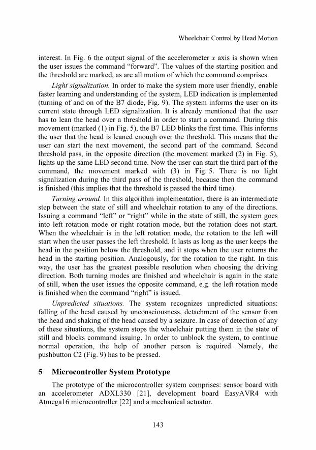
The accelerometer board schematic is shown in Fig. 7. This accelerometer
measures linear acceleration in all three axes within the ±3g range. The
integrated circuit contains polysilicium sensor and the circuits required to shape
the signal. The output signal voltages are proportional to the acceleration.
Fig. 7 – The accelerometer board schematic [21].
The mechanical actuator, shown in Fig. 8, is designed and produced within
this paper. The actuator is supposed to put the wheelchair joystick in the
position that corresponds the user’s command. The actuator is powered by two
HS-424 servomotors [23].
During the work on this paper, we first tried to use the direct way of
controlling the wheelchair motors. However, different manufacturers use
different communication protocols or different messages within the same
protocol. Often, these protocols are proprietary and, thus, unavailable to the
public. So, in order to perform direct control of the wheelchair motors, the
protocol and the messages need to be decoded. Such operation is highly time
consuming and it does not offer modularity, since different wheelchair types use
different protocols.
Otto Bock Bx00 wheelchair family is taken into account during the design
and production of the mechanical actuator. The dimensions of interest were
measured on different types and then, the actuator is produced so that it fits to
all of them. Also, it can be easily modified for more wheelchair types.
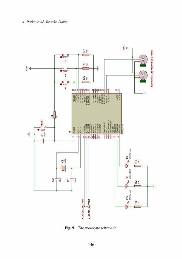
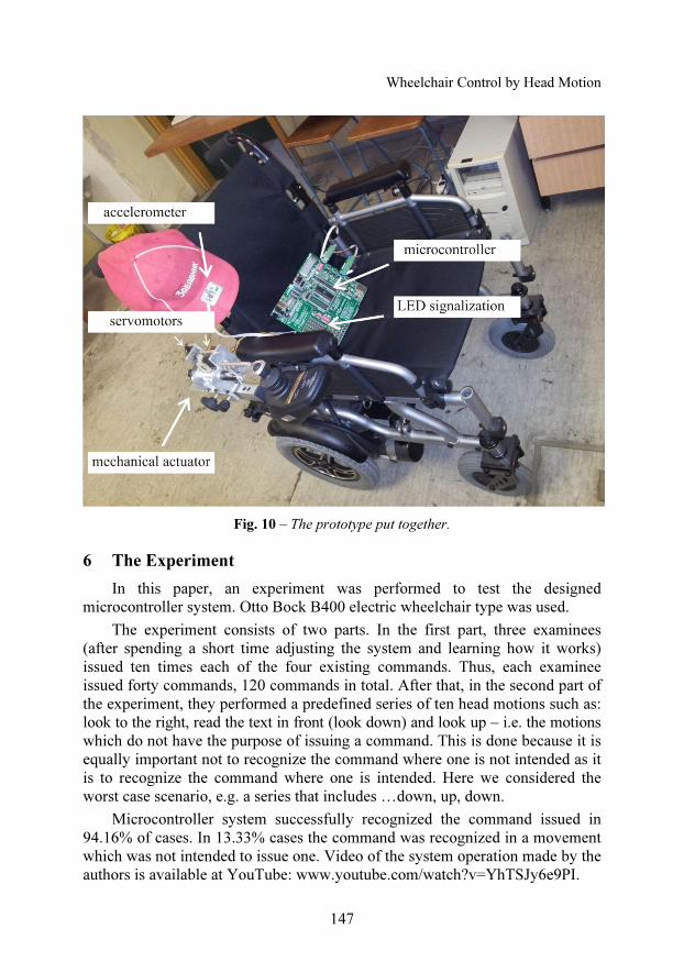
The complete prototype is shown in Figs. 9 and 10.
Wheelchair Control by Head Motion
145
(a)
(b)
Fig. 8 – The mechanical actuator: a) the specification drawing and
b) the produced aluminum actuator.
A. Pajkanović, Branko Dokić
146
Fig. 9 – The prototype schematic.
Wheelchair Control by Head Motion
147
Fig. 10 – The prototype put together.
6 The Experiment
In this paper, an experiment was performed to test the designed
microcontroller system. Otto Bock B400 electric wheelchair type was used.
The experiment consists of two parts. In the first part, three examinees
(after spending a short time adjusting the system and learning how it works)
issued ten times each of the four existing commands. Thus, each examinee
issued forty commands, 120 commands in total. After that, in the second part of
the experiment, they performed a predefined series of ten head motions such as:
look to the right, read the text in front (look down) and look up – i.e. the motions
which do not have the purpose of issuing a command. This is done because it is
equally important not to recognize the command where one is not intended as it
is to recognize the command where one is intended. Here we considered the
worst case scenario, e.g. a series that includes …down, up, down.
Microcontroller system successfully recognized the command issued in
94.16% of cases. In 13.33% cases the command was recognized in a movement
which was not intended to issue one. Video of the system operation made by the
authors is available at YouTube: www.youtube.com/watch?v=YhTSJy6e9PI.
A. Pajkanović, Branko Dokić
148
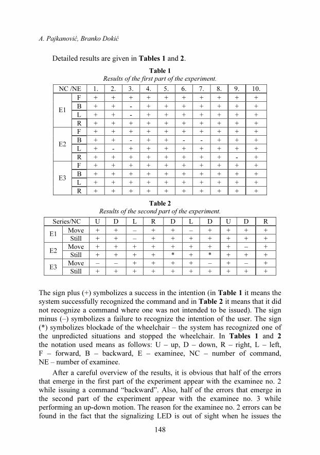
Detailed results are given in Tables 1 and 2.
Table 1
Results of the first part of the experiment.
NC /NE 1. 2. 3. 4. 5. 6. 7. 8. 9. 10.
F + + + + + + + + + +
B + + - + + + + + + +
L + + - + + + + + + + E1
R + + + + + + + + + +
F + + + + + + + + + +
B + + - + + - - + + +
L + - + + + + + + + + E2
R + + + + + + + + - +
F + + + + + + + + + +
B + + + + + + + + + +
L + + + + + + + + + + E3
R + + + + + + + + + +
Table 2
Results of the second part of the experiment.
Series/NC U D L R D L D U D R
Move + + – + + – + + + + E1
Still + + – + + + + + + +
Move + + + + + + + + – + E2
Still + + + + * + * + + +
Move – – + + + + – + – + E3
Still + + + + + + + + + +
The sign plus (+) symbolizes a success in the intention (in Table 1 it means the
system successfully recognized the command and in Table 2 it means that it did
not recognize a command where one was not intended to be issued). The sign
minus (–) symbolizes a failure to recognize the intention of the user. The sign
(*) symbolizes blockade of the wheelchair – the system has recognized one of
the unpredicted situations and stopped the wheelchair. In Tables 1 and 2
the notation used means as follows: U – up, D – down, R – right, L – left,
F – forward, B – backward, E – examinee, NC – number of command,
NE – number of examinee.
After a careful overview of the results, it is obvious that half of the errors
that emerge in the first part of the experiment appear with the examinee no. 2
while issuing a command “backward”. Also, half of the errors that emerge in
the second part of the experiment appear with the examinee no. 3 while
performing an up-down motion. The reason for the examinee no. 2 errors can be
found in the fact that the signalizing LED is out of sight when he issues the
Wheelchair Control by Head Motion
149
command “backward”. That means that the examinee has no information on
whether he moved the head enough or not. By optimizing the threshold value, in
other words with fine tuning and more often use of the system, such errors can
be minimized. Also, changing the place of the signalizing LED can ease the
process of command issuing.
The examinee no. 3 had problems with free head motion. Namely, in the
series given in Table 2, there are three motions that end with the head leaned
forward, i.e. looking down – with this examinee, the system recognized the
command “forward” each time where none were intended. A potential solution
to this kind of problem is additional sensor data – completing the inertial
navigation system by adding a gyroscope. Also, the fact that in this series we
considered the worst case scenario (down-up-down) has to be accounted. Such
motions should be avoided and the user should take care of the command time
frame. So, slower motions when no command is intended are suggested.
The researches performed in [1 – 4]; show that the psychological condition
of the patient greatly influences his ability to control the wheelchair. According
to [24], the addition of an obstacle detection subsystem to the wheelchair can
increase self-esteem. Taking into account these researches, we can conclude that
some errors in our experiment emerged because the examinees were controlling
the wheelchair in a very unusual way and in a very narrow indoor environment
without any kind of protection.
7 Conclusion
Within this paper a novel technique of head motion recognition is used to
enable wheelchair control for quadriplegics. The technique is implemented as
an algorithm of microcontroller system. A prototype of this system is
experimentally tested. The performed experiment showed very good results.
Namely, after adapting the system and a short learning time, three different
examinees issued commands with 94.16% success. A larger number of errors
appears when the user makes free head motions, the purpose of which is not
issuing commands. In this case, in 13.66% cases the system recognizes a
command where one was not intended.
The prototype consists of an electronic and a mechanical part. It is designed
to be characterized by low price and high level of modularity. Namely, it can be
used with several different types of standard electric wheelchairs.
In future work we plan to complete the inertial navigational system by
including the gyroscope. We assume that the usage of the additional sensor
would improve the ability of the system to recognize the user’s commands.
Also, the experiments to test the applicability of this system in real conditions
are needed: (1) integrate the control of the wheelchair motors and repeat the
experiment performed in this paper and (2) when the system becomes precise
A. Pajkanović, Branko Dokić
150
and reliable enough perform an experiment which would include actual
quadriplegics.
8 Acknowledgment
This paper is done within a project financed by the Ministry of Science and
Technology, Government of The Republic of Srpska, titled: “Wireless
communication technologies in medical applications”, under contract number:
19/6-020/964-91/10, date: December 21st, 2010.
9 References
[1] U. Cortés, C. Urdiales, R. Annicchiarico, C. Barrué, A.B. Martinez, C. Caltagirone: Assistive
Wheelchair Navigation: A Cognitive View, Studies in Computational Intelligence:
Advanced Computational Intelligence Paradigms in Healthcare – 1, Vol. 48, 2007, pp. 165 – 187.
[2] A. Landi: Update on Tetraplegia, Journal of Hand Surgery, Vol. 28, No. 3, June 2003,
pp. 196 – 204.
[3] N.I. Katevas, N.M. Sgouros, S.G. Tzafestas, G. Papakonstantinou, P. Beattie, J.M. Bishop,
P. Tsanakas, D. Koutsouris: The Autonomous Mobile Robot SENARIO: A Sensor Aided
Intelligent Navigation System for Powered Wheelchairs, IEEE Robotics and Automation
Magazine, Vol. 4, No. 4, Dec. 1997, pp. 60 – 70.
[4] G. Bourhis, O. Horn, O. Habert, A. Pruski: An Autonomous Vehicle for People with Motor
Disabilities, IEEE Robotics and Automation Magazine, Vol. 8, No. 1, March 2001, pp. 20 – 28.
[5] A. Lankenau, T. Rofer: A Versatile and Safe Mobility Assistant, IEEE Robotics and
Automation Magazine, Vol. 8, No. 1, March 2001, pp. 29 – 37.
[6] M. Mazo: An Integral System for Assisted Mobility (Automated Wheelchair), IEEE
Robotics and Automation Magazine, Vol. 8, No. 1, March 2001, pp. 46 – 56.
[7] H.A. Yanco: Wheelesley: A Robotic Wheelchair System: Indoor Navigation and User
Interface, Lecture Notes in Artificial Intelligence, Vol. 1458, Assistive Technology and
Artificial Intelligence, Applications in Robotics, User Interfaces and Natural Language
Processing, Berlin, Springer, Germany, 1998, pp. 256 – 268.
[8] C.H. Kuo, H.H.W. Chen: Human-oriented Design of Autonomous Navigation Assisted
Robotic Wheelchair for Indoor Environments, IEEE International Conference on
Mechatronics, Budapest, Hungary, 03 – 05 July 2006, pp. 230 – 235.
[9] J.M. Detriche, B. Lesigne: Robotic system MASTER, European Conference on the
Advancements of Rehabilitation Technology, Maastricht, Pays-Bas, Holland, 05 – 08 Nov.
1990, pp. 12 – 15.
[10] J.L. Jaffe: A Case Study: The Ultrasonic Head Controlled Wheelchair and Interface,
OnCenter: Technology Transfer News, Vol. 1, No. 2, 1990.
[11] R.C. Simpson, S.P. Levine: Voice Control of a Powered Wheelchair, IEEE Transactions on
Neural Systems and Rehabilitation Engineering, Vol. 10, No. 2, June 2002, pp. 122 – 125.
[12] P. Pino, P. Amoud, E. Brangier: A More Efficient Man Machine Interface: Fusion of the
Interacting Telethesis and Smart Wheelchair Projects, 2nd International Conference on
Knowledge-based Intelligent Electronic System, Adelaide, Australia, 21 – 23 April 1998,
pp. 41 – 45.
Wheelchair Control by Head Motion
151
[13] H.A. Yanco: Integrating Robotic Research: A Survey of Robotic Wheelchair Development,
AAAI Spring Symposium on Integrating Robotic Research, Stanford, CA, USA, March
1998.
[14] M. Slavkovic, D. Jevtic: Face Recognition using Eigenface Approach, Serbian Journal of
Electrical Engineering, Vol. 9, No. 1, Feb. 2012, pp. 121 – 130.
[15] S. Mitra, T. Acharya: Gesture Recognition: A Survey, IEEE Transactions on Systems, Man,
and Cybernetics, Part C: Applications and Reviews, Vol. 37, No. 3, May 2007, pp. 311 – 324.
[16] L.R. Rabiner: A Tutorial on Hidden Markov Models and Selected Applications in Speech
Recognition, Proceedings of the IEEE, Vol. 77, No. 2, Feb. 1989, pp. 257 – 286.
[17] S.K. Pal, S. Mitra: Neuro-fuzzy Pattern Recognition: Methods in Soft Computing, John
Wiley and Sons, NY, USA, 1999.
[18] J. Liu, L. Zhong, J. Wickramasuriya, V. Vasudevan: uWave: Accelerometer-based
Personalized Gesture Recognition and Its Applications, Pervasive and Mobile Computing,
Vol. 5, No. 6, Dec. 2009, pp. 657 – 675.
[19] H. Junker, O. Amft, P. Lukowicz, G. Tröster: Gesture Spotting with Body-worn Inertial
Sensors to Detect User Aactivities, Pattern Recognition, Vol. 41, No. 6, June 2008, pp. 2010
– 2024.
[20] T. Schlömer, B. Poppinga, N. Henze, S. Boll: Gesture Recognition with a Wii Controller,
2nd international Conference on Tangible and Embedded Interaction, NY, USA, pp. 11 – 14.
[21] mikroElektronika, Three-Axis Accelerometer Board, 2012. Available on:
http://www.mikroe.com/eng/products/view/133/three-axis-accelerometer-board/
[22] mikroElektronika, Development Tools, 2012. Available on:
http://www.mikroe.com/eng/products/view/321/easyavr6-development-system/
[23] Hitec, Hitec HS-422, 2012. Available on: http://www.hitecrcd.com/products/servos/analog/
standard-sport/hs-422.html.
[24] M. Urbano, J. Fonseca, U. Nunes, H. Zeilinger: Extending a Smart Wheelchair Navigation
by Stress Sensors, 16th Conference on Emerging Technologies and Factory Automation,
Toulouse, France, 05 – 09 Sept. 2011, pp. 1 – 4.