when “yes” is the wrong answer
TRANSCRIPT

When “Yes” is the Wrong Answer
Richard Beasley, Andy J. Nolan and Andrew C. Pickard
Rolls-Royce plc [email protected], [email protected], [email protected]
Copyright © 2014 Rolls-Royce plc. Permission granted to INCOSE to publish and use.
Abstract: Systems Engineering’s value comes from doing effective pre-work to avoid later,
expensive rework. There are many barriers to uptake of Systems Engineering, including the
difficulty of abstract and holistic thinking and project time pressures. This paper focuses on
the time pressures, and the usual desire to show positive progress in any form of review of a
project. This leads to a behavior where there is a tendency to say “yes” in answer to a
question because we know it is the desired answer. Inappropriate “yes” statements to
questions like “Are the requirements complete?” result in a tendency to stop the pre-work,
and start the solution stage pre-maturely or with false confidence. The paper proposes as a
heuristic that the Systems Engineer recognizes that there are implicit dangers in answering
“yes” to many review type questions.
Introduction
This paper emphasizes the need to recognize uncertainty and embrace it. In previous work
exploring the barriers to the uptake of Systems Thinking (Beasley, 2012) the “curse of the
Gantt chart” was described as one of the barriers – there is a need to see perceptible progress
and a pervading management ideal of a progressing, waterfall style of steady reduction in risk
and uncertainty. This translates into a need to see / show definite progress, represented by the
need for positive “yes” answers in program development. This paper proposes a greater
focus on uncertainty, and acknowledging the inherent iteration in program plans to handle
this.
A significant part of the way Systems Engineering delivers value is by exposing uncertainty
early (when it is cheap to address) and preventing the certainty of emergent problems later in
the program – with a need for expensive rework through traditional, late program firefighting.
This paper is structured as follows:
A discussion of specific issues where “yes” is the wrong answer, including some
examples which reflect more widely on the systems approach than just the need for
managing uncertainty and iteration
A discussion of the means by which Systems Engineering delivers value
A discussion and comparison of the dangers and difficulties inherent in linear
planning approaches
Introduction of new heuristics focused on the value of recognizing uncertainty early in
the program, and the program mindset that is needed to exploit this.
Conclusions
Examples where “yes is the wrong answer These are a series of examples where there is either a strong desire from the Program, (or in
one case regarding attitude to the customer, the engineer) to give or be given the answer
“yes”. An explanation is given of where that pressure comes from, and why it should be
resisted.

Question 1: Are your requirements complete?
There is near unanimous agreement that successful projects depend on meeting the needs and
requirements of the stakeholder / customer, and this depends on gathering, understanding and
recording those requirements, and paying attention to them during solution creation.
Gathering of requirements is first step in most lifecycle models (INCOSE SE Handbook,
2011).
Therefore asking the question “are your requirements complete” is, at first glance, an entirely
sensible question to ask, and also important to ask at the beginning of the work of a design
team. There are three problems with the apparent simplicity of this question:
1) It ignores the iteration needed between requirements and design, illustrated in simple
figure below.
Clearly the purpose of requirements is to constrain (and drive) the solution – decisions
between alternative options are made on the basis of which one satisfies the requirements.
Concepts are adapted / changed to make a better fit to the requirements. However, with
complex products the emerging nature of the solution will identify issues for which
requirements have not been defined. This is particularly true when new technologies are
used – there will be new failure modes that have not been previously experienced, and
specific requirements are needed to define what is tolerable. At the most extreme this is
the “wicked problem” where you can’t know the requirements until the solution is
complete (Conklin, 2006).
It needs to be clearly recognized, despite all the desires of Program Management and the
dominance of the “Gantt chart” view, that engineering complex products is iterative
rather than linear.
2) Observed practice is that the question is normally asked at the start of the system creation
process – with the apparent expectation that the requirements arrive to the team
“complete and gift-wrapped”. Experience shows that this is not the case – customers
rarely give complete requirements. Even if the customers do define all their needs in
well-structured requirements this is not enough. Firstly, at every level in the system there
are additional stakeholders, and so there needs to be an identification of the stakeholders
for each level of the system. This point was emphasized in the updated V-model views
(Forsberg et al, 2013). To illustrate from our experience, engine requirements have
airframe / airline customer needs, but there are also business needs. Our customers may
want us to survive as a company to provide continuity of supply, but they do not have the
Figure 1. Requirements and Solutions

same view about desired Return on Investment that Rolls-Royce’s shareholders have. At
component level the component designer needs to balance / integrate the specific needs of
the project / product with the Product Line / design style (reuse of design knowledge
across multiple products), and the long term supplier relationships – requirements the
“product” customer cannot set.
3) You don’t want customers to set requirements that conflict with your design style or
Product Line; setting of requirements needs to be a negotiation and agreement process
playing to the strengths of both the “customer” and the “supplier”. This takes time.
If the question “are your requirements complete?” is asked during a review, and the answer is
“no”, typically the project will fail the review. This can have the unintended consequence of
design teams “hiding” the uncertainty, and the issues that are uncertain getting lost in the
“false optimism”. It is the authors’ contention that the answer “yes” at the front end of a
program should be considered a fail. Completeness of requirements is not what we should be
tracking. We should value the level of communication and engagement with the stakeholders
and the maturity of information from which requirements are developed (e.g. engine models,
aircraft models, past experience); the thing that should be tracked is how well the uncertainty
has been mapped, characterized and documented. The impact of the uncertainty should be
reviewed - and in particular the time criticality (when is the requirement needed to constrain a
design choice and the absence of constraint leads to later rework). Requirements uncertainty
needs to be treated as an important input to technical risk identification (Pickard, Nolan and
Beasley, 2010).
Here is a simple example to illustrate the point. Consider the requirement “the engine shall
be painted”. Basic requirements analysis will show this does not conform to any sort of good
requirements standard. Issues to be addressed include:
What is meant by the engine? Is it all parts of the engine (inside and out), the visible
parts or the outside?
Why “paint”? This is a solution, not a requirement. Is the value from adding color to
the surface, protecting the surface, reflecting sunlight, or displaying a brand image?
What type or color of paint? – is that the customer’s (as yet undefined) requirement,
or is the choice left to the supplier?
Are there any special properties of the paint needed (the environment it must last in,
how long it must last, and in some military contexts, does it need to have any
reflective/emission properties)?
The point is not that there are issues with the requirement, but when does it need to be
mature. There are some requirements engineers who suggest that an immature requirement
like that above “should not be released into the wild with the designers until mature” (!!)
This is wrong – the designers can raise the questions that need to be asked to get the complete
requirement – prompted by the knowledge that “Painting is required”. Knowing painting is
needed can be included in trades and manufacturing process preparation and costing – e.g. the
addition of a paint shop capability – well in advance of knowing the final details of the color.
So the issue is with asking the wrong question. Rather than asking “are your requirements
complete?” the question should be split into a) “Are your requirements complete enough for
decisions that need to be made at this stage?” and b) “Have you sufficient work planned to
improve the maturity of requirements in timely manner?” Credible answers of “yes” to both
these questions would give far more confidence that rework will be avoided.

Question 2: Have you used stage gates / independent review?
Independent audits are an established part of good engineering practice. These are separate
to the internal design review gates where decisions to proceed are taken. Commonly they are
used as a “second pair of eyes” to ensure the project team are not taking inappropriate risks.
In Rolls-Royce the independent audit is driven by the risk process.
Review (independent or otherwise) and clear decision gates and milestone reviews are
important. But there are significant dangers with audits and reviews. It is commonly stated
that “you cannot inspect quality in” – and there is a significant risk that this is what the
review process does. A review is an important check that the right things have been done
correctly, but it can have negative effects. There can be a lack of openness at a review,
“hiding the dirty linen”, and expecting the review/audit team to find the problems themselves.
This is driven by a natural desire not to be criticized and have work rejected, by a belief that
the design team is professional and on the right track, and by pressure from the Program
Manager not to slip the schedule by diverting resources to address audit actions. This can,
despite the best intentions, turn the review into an adversarial challenge rather than the well-
intentioned opportunity to pause and check.
Further, the effectiveness of reviews can depend strongly on the level of empowerment of a
project team. Figure 2 shows correlation between levels of product innovation (a measure of
merit related to a new product being better than previous) and the effects that use of stage
gate reviews can have on innovation. There are two graphs – one where there is a high level
of bounded empowerment, and one where there is low. Bounded empowerment is defined as
the degree to which the team is free to make its own decisions and has the self-confidence to
move forward. High bounded empowerment would be characterized by “yes” responses to
questions such as:
Are development teams given a charter specifying what they are expected to do?
Are product development teams empowered to make decisions traditionally reserved
for management?
Are project teams semi-autonomous and proceed on their own initiative so long as
they are within specified boundary conditions?
Are project teams largely responsible for continuously reviewing their actions to
ensure they are within boundary conditions?
So while it is conventional (and
intuitively correct) to hold stage gates
and reviews, carrying them out
(answering “yes” to the question about
reviews) is not necessarily a good thing.
You need to be sure that both the
organization and the team are “mature”
enough to take advantage. An
organization that does not empower its
teams will get “well, you check”
behaviors in reviews, and a team that is
not confident in its autonomy and
capability will look for errors / problems
to be spotted by the “wiser” review /
audit team.
Figure 2. Effect of Bounded Empowerment on
Stage Gates and Innovation
1.5
2
2.5
3
3.5
4
1.5 2 2.5 3 3.5 4
Pro
du
ct In
no
vati
on
Extent of use of Stage Gates
High Bounded Empowerment
Low Bounded Empowerment

Question 3: Do you understand all of the interfaces?
Systems Engineering best practice has emphasized the importance of interfaces. How often
have we seen projects run into problems because the interfaces were not understood? So it is
natural to ask this question, and it is also important to elicit an honest response. But projects
often do not understand the interfaces as well as they might think. Heuristics can be very
helpful in understanding issues within an organization that need to be addressed to improve
performance.
The authors collected 238 heuristics from a variety of sources (Rechtin and Maier, 2007;
Gasser, 2008; Gilb, 2007; Valerdi, 2010) relating to Systems Engineering, Systems
Architecting and Estimation. From this list, 42 were selected that were particularly important
in understanding the behaviour of an organization. Two surveys were performed. For the first
survey, 50 people in the organization were asked to review the heuristics and identify those
that they thought applied to
the organization. For the
second survey, another 50
(different) people were asked
to review the heuristics and
identify those that they
thought the organization
applied during the
development of products. 22
people responded to the first
survey, and 19 to the second
(around 40%, and typical for
this type of survey).
The results were then cross-
plotted as shown in figure 3.
Six of the heuristics related to interfaces:
Q7 It is inadequate to architect up to the boundaries or interfaces of a system; one must
architect across them
Q8 Be prepared for reality to add a few interfaces of its own
Q11 Choose a configuration with minimal communications between the subsystems
Q16 The greatest leverage in system architecting is at the interfaces; the greatest dangers are
also at the interfaces
Q25 Organize personnel tasks to minimize the time individuals spend interfacing
Q27 Modularity - To build a durable system, keep integration low between modules
Interestingly, the responses for all of these lie in the bottom right quadrant (applies to the
organization but the organization does not apply), with two (heuristics 7 and 8) in the pink-
shaded sector where there is most discrepancy between “applies to” and “applies”. This
points to a weakness in the management of interfaces which, having been identified, can now
be addressed by focused training.
Q1
Q2
Q3
Q4
Q5
Q6
Q7
Q8
Q9
Q10
Q11
Q12
Q13
Q14
Q15
Q16
Q17
Q18
Q19
Q20
Q21
Q22
Q23
Q24
Q25
Q26Q27
Q28
Q29
Q30
Q31
Q32
Q33
Q34
Q35
Q36
Q37
Q38
Q39
Q40
Q41
Q42
0.0%
50.0%
100.0%
0.0% 50.0% 100.0%
Org
aniz
atio
n A
pp
lies
Applies to Organization
Heuristics
Figure 3. Heuristics Survey Results

Question 4: Have you mitigated all of the risks?
Sometimes it is appropriate to take a calculated risk, because this generates a business
opportunity. The following example shows how calculated risks are taken with the
development of Product Lines.
Imagine having to define the scope of a Software Product Line (SPL) (Nolan, Abrahão,
Clements and Pickard, 2011). How much functionality should be included beyond that needed
for the known applications of the Product Line? If too little is included, then new applications
may not be able to use the Product Line or
expensive rework will be required. If too
much is included, then the extra
functionality adds cost but little value.
Consider Figure 4. The box represents the
full range of the domain, the green circles
represent known projects within the
domain and the amber shaped area
represents the scope of a SPL. How do we
identify the most economical shape (and
size) for the scope of the SPL?
Fig. 5 shows some scenarios of the SPL boundary
relative to known projects. If the scope is
defined too far away from any known
requirement (example B in Figure 5) i.e., there
is more functionality than required, the project
will incur a cost with no benefit. In safety-
critical software this is a very expensive option.
If the scope is set too close to the known
requirements (example A in Figure 5), the
project runs a risk of needing to make costly
modifications late in the product line life.
However, in safety-critical software, with
the certification activities, it is tempting
to define the boundary of the SPL as
close as possible to the known
functionality required. To determine the
“sweet spot” for the scope of the SPL
(example C in Figure 5), the principle of
risk/mitigation trade-off analysis can be
used.
The “sweet spot” can be calculated as the
ratio between the impact to a SPL from a
new emergent requirement (defined here
as risk) and the costs to mitigate this risk
through the initial core asset design
(mitigation). There are some cases when
it is economical to move from scenario B
Figure 4. An illustration of the full range of functionality available across the domain, the scope of the SPL and individual projects within the SPL covered by the scope of the SPL.
Figure 5. Three scenarios showing the boundary of the SPL functionality relative to the known functional requirements.
Figure 6. A theoretical cost-benefit trade between risk and mitigation costs. The figure shows a theoretical functional “sweet spot” when the business achieves maximum return-on-investment.
The SPL boundary lies
far away from any
known project i.e. the
scope of the SPL
contains significantly
more functionality
than is known about
The SPL boundary lies close
to the known project i.e. the
scope of the SPL contains no
additional functionality other
than the known requirements
The SPL boundary
lies at an optimal
distance

(Figure 6) to scenario A. For example, the “starting” function of an engine can be very specific
to an engine type and the airframe. The range of functionality and options is so large (scenario
B) that it is economical to create several smaller core assets (scenario C) or to develop
bespoke solutions for each engine/customer combination (scenario A).
The boundary of any SPL functionality should be based on both anticipated requirements
changes and business opportunities that may exist beyond the boundary. Implicit within
requirements uncertainty analysis is sensitivity analysis. There may be some requirements that
can be extended with little or no mitigation costs; whereas, there may be requirements which
have a high sensitivity to change or discontinuities in the impact.
As an example, consider the selection of a temperature probe used on an engine. The operating
temperature of an engine may not be known precisely at the start of a project. Different
probes can be used dependent on the temperature required but some probes, those for higher
temperatures, can be heavier and more costly. However, a more expensive probe can meet a
wider range of engine temperatures. There is a direct trade between flexibility and net cost to
the business. Risk analysis can be used to determine the probability the engine temperature
will exceed a probe’s capability and, therefore, if it is better to adopt a more expensive probe
now, or later when the true temperatures are determined.
As late changes can be expensive to an engine and to a SPL, these analysis techniques are
intended to determine if it is better to take a risk and develop the functionality now, or to wait
and develop the functionality later. If the risk (probability or impact) is high enough, it may be
better to develop the capability (mitigate the risk) up front. If the risk is low enough, it may be
better to wait for it to manifest. Mitigating all of the risks is unlikely to be the best strategy.
Question 5: Are you going to get it right first time?
Gas turbine engines create harsh environments for components – high temperatures and
thermal gradients, massive levels of heat transfer, high static and dynamic stresses – and
systems and components have to perform reliably in these environments for years between
maintenance tear-downs. Designing systems and components to survive in these
environments is often a form of wicked problem – you need to know the environment to
complete the design, but you need to have tested the design to know the environment.
An engine development program is intended to de-risk these problems; heavily instrumented
engines are run and temperature and stress measurements are made to calibrate the models
used during the design of the engine. As the models are adjusted, decisions are made on the
need to iterate the design of systems or components to achieve the required system
performance.
When planning the program, a good program manager will know to build in these planned
design iterations when there is high risk that the engine development program will turn up
issues, and will not assume that the initial design will be the final design. Sometimes the
iteration is not needed – a pleasant surprise. What happens, though, when it is assumed that
the design will be “right first time”, with no planned iterations?
There is more to this than just poor planning. Because it is assumed that the design will be
“right first time”, it is often subjected to all of the rigors of satisfying engine certification
requirements – it must be “production standard” and must have passed all of the testing to
achieve certification requirements. Then, when a redesign is required, all of this will have to
be repeated for the new design.
The aim of the engine development program is to gather information. The systems and
components that are assembled to create the development engine need to be good enough to
do this – not to pass engine certification requirements at the first attempt. For instance,
machining mounting brackets out of solid material may not be a viable production solution,
but it is far less expensive for a “one-off” than creating the forging that would be used for the
final design, and has the added benefit of flexibility. Changes can be made to the bracket
design without having to procure new, long lead-time forgings. Planned iteration is good!
Question 6: Have you got a solution yet?
Project pressures tend to drive projects towards valuing progress in terms of defined solutions
rather than in terms of problem understanding. Root cause analysis is difficult, and there is a
tendency to assume that the root cause is known and jump quickly into developing a solution
without really understanding the problem.
A project was launched several years ago in Rolls-Royce to look at design modifications to
understand:
Where (in the design and development process sequence) was the problem with the
original design found?
Where should the problem with the original design have been found?
What was the problem with the original design that was the root cause of the need for
the modification?
If the problem was found later in the design and development process sequence than it
should have been found, what was the root cause of the escape?
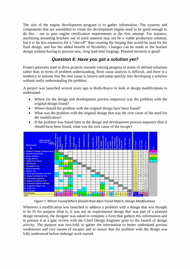
Wherever a modification was launched to address a problem with a design that was thought
to be fit for purpose (that is, it was not an experimental design that was part of a planned
design iteration), the designer was asked to complete a form that gathers this information and
to present it at a gate review with the Chief Design Engineer prior to the launch of design
activity. The purpose was two-fold; to gather the information to better understand process
weaknesses and root causes of escapes and to ensure that the problem with the design was
fully understood before redesign work started.
1 -
Sett
ing
or
Ch
an
ge
of
Req
uir
em
en
ts
2 -
Req
uir
em
en
ts
Revie
w
3 -
Desig
n A
naly
sis
4 -
Desig
n R
evie
w
5 -
Su
pp
ly C
hain
Issu
es
6 -
Man
ufa
ctu
re
7 -
Co
mp
on
en
t T
est
8 -
Mo
du
le A
ssem
bly
9 -
Mo
du
le T
est
10 -
Develo
pm
en
t
En
gin
e A
ssem
bly
11 -
En
gin
e
Develo
pm
en
t T
est
12 -
Fir
st
Art
icle
Insp
ecti
on
13 -
En
gin
e
Cert
ific
ati
on
Test
14 -
Pro
du
cti
on
En
gin
e A
ssem
bly
15 -
Pro
du
cti
on
En
gin
e T
est
16 -
Fli
gh
t T
est
17 -
In
Serv
ice
Cost
Weig
ht
Cost
if f
ound
at
right
sta
ge
Actu
al cost
Key:
1 - Setting or Change of Requirements 37 1 4 1 56 42 >= 20
2 - Requirements Review 2 3 1 21 5 10 to 19
3 - Design Analysis 3 1 15 1 1 69 20 5 to 9
4 - Design Review 2 5 4 10 1 63 21 2 to 4
5 - Supply Chain Issues 1 1 6 5 2 12 26 1
6 - Manufacture 1 3 5 2 1 10 2 24 44
7 - Component Test 1 11 3 2 5 20 85
8 - Module Assembly 5 2 3 1 10 10 110
9 - Module Test 2 10 30 20
10 - Development Engine Assembly 1 3 4 1 25 50 225
11 - Engine Development Test 1 13 13 1 1 1 22 25 950 1300
12 - First Article Inspection 1 25 0 25
13 - Engine Certification Test 1 1 50 50 100
14 - Production Engine Assembly 1 1 100 0 200
15 - Production Engine Test 2 4 100 0 600
16 - Flight Test 1 1 2 1 1 3 1 100 0 1000
17 - In Service 7 14 16 1 1 8 12 1000 12000 59000
Total Escapes 19 18 54 53 1 2 2 0 1 1 16 0 1 0 0 0 12 Total: 13355 62823
Total 56 22 69 67 6 12 4 1 3 3 38 0 1 0 0 0 12 470%Cost Ratio:
Where Found
Where Should Have Been Found
Figure 7. Where Found/Where Should Have Been Found Matrix, Design Modifications
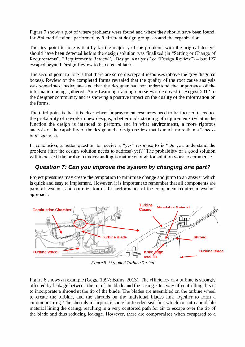
Figure 7 shows a plot of where problems were found and where they should have been found,
for 294 modifications performed by 9 different design groups around the organization.
The first point to note is that by far the majority of the problems with the original designs
should have been detected before the design solution was finalized (in “Setting or Change of
Requirements”, “Requirements Review”, “Design Analysis” or “Design Review”) – but 127
escaped beyond Design Review to be detected later.
The second point to note is that there are some discrepant responses (above the grey diagonal
boxes). Review of the completed forms revealed that the quality of the root cause analysis
was sometimes inadequate and that the designer had not understood the importance of the
information being gathered. An e-Learning training course was deployed in August 2012 to
the designer community and is showing a positive impact on the quality of the information on
the forms.
The third point is that it is clear where improvement resources need to be focused to reduce
the probability of rework in new designs; a better understanding of requirements (what is the
function the design is intended to perform, and in what environment), a more rigorous
analysis of the capability of the design and a design review that is much more than a “check-
box” exercise.
In conclusion, a better question to receive a “yes” response to is “Do you understand the
problem (that the design solution needs to address) yet?” The probability of a good solution
will increase if the problem understanding is mature enough for solution work to commence.
Question 7: Can you improve the system by changing one part?
Project pressures may create the temptation to minimize change and jump to an answer which
is quick and easy to implement. However, it is important to remember that all components are
parts of systems, and optimization of the performance of the component requires a systems
approach.
Figure 8 shows an example (Gegg, 1997; Burns, 2013). The efficiency of a turbine is strongly
affected by leakage between the tip of the blade and the casing. One way of controlling this is
to incorporate a shroud at the tip of the blade. The blades are assembled on the turbine wheel
to create the turbine, and the shrouds on the individual blades link together to form a
continuous ring. The shrouds incorporate some knife edge seal fins which cut into abradable
material lining the casing, resulting in a very contorted path for air to escape over the tip of
the blade and thus reducing leakage. However, there are compromises when compared to a
Combustion Chamber
Combustion Chamber
Turbine Blade
Shroud
Knife edge
seal fin
Turbine
Casing
Turbine Blade
Abradable Material
Turbine Wheel
Combustion Chamber
Figure 8. Shrouded Turbine Design

shroudless design; the blade is heavier, which makes design of the wheel holding the blades
harder, more blades are required because the design of the shroud becomes difficult as the
cantilever overhang is increased, and the shroud has to be kept relatively cool to achieve a
reasonable life.
Two teams within Rolls-Royce ran some trade studies to compare shrouded and shroudless
designs, but one team found that the sensitivity of the efficiency of the shroudless blade to tip
clearance was approximately twice that observed by the other team. In the subsequent
investigation it was found that the first team, who were more familiar with designing
shrouded blades, had simply substituted a shroudless blade design and had left the radial
distribution of heat from the combustion chamber the same as for the shrouded design, with
cooler air around the tip of the blade. The second team, more familiar with designing
shroudless blades, had also moved the hot stream from the combustor out towards the tip of
the blade for the shroudless design – there was no shroud to protect with cooler air. Now for a
given tip clearance, the volume of air escaping over the tip of the blade is constant, but the
hotter the air, the less dense it is, so the second team’s design had lower mass flow over the
tip of the blade, and this is the factor that drives the efficiency loss and hence the sensitivity
to tip clearance.
The lesson here is that optimization has to be performed at the system level and there has to
be an understanding of all of the factors that can influence the performance of the system.
Question 8: It’s only a small change - can I skip the analysis & test?
When significant changes are made to a product, they tend to receive a lot of attention, are
thoroughly reviewed and risks are identified and mitigated.
Strangely enough, though, it is often the small changes that need more risk assessment and
mitigation, because it is too easy to make invalid assumptions, for instance on read-across
from similar designs. But the small changes will often be sold as “minor” updates which do
not require the costs of detailed reviews. There may be a temptation to skip the analysis and
testing.
A case in point was a hardware modification to change a spring in an Air Flow Control
Regulator to overcome some issues with aircraft gas turbine engine handling at altitude. This
had already been done on a later variant of the engine, and the temptation was to think that
this was just a small change – a “no-brainer” – there were no technical risks on the risk
register.
However, the team started thinking and assessing the technical risks associated with the
change:
The air flow control regulator was designed and developed by a different team. How
much technical knowledge do we have of how it works?
Why would changing the spring solve the problem? What other changes are involved?
How is the unit to be calibrated – can we read across the calibration from the later
variant of the engine, or do we have to establish a new calibration – how?
The schedule of the regulator is set in service on the later application using a test set.
The update to the test set for the new application may take longer than the
modification to the unit.

Manuals (Operator’s Manual, etc.) will need to be updated to instruct the
modification, the calibration activity and the new test set for scheduling the regulator
– how long will these take to update?
A “simple” change is often not so simple when sweeping assumptions are swept aside by
clear thinking and a realistic assessment of risk.
Question 9: Do you think your customer is an idiot?
This one is a bit different to the others, because the answer “yes” is not expected – especially
if it is the customer asking!
However, in discussions with many systems engineers we find this to be a widely held belief.
There is a belief that the customer (by which we mean the system level above the one the
team is working) doesn’t really know what they want, and if only they did the design team’s
life would be significantly easier. Therefore the answer “yes” to this question is prevalent,
and dangerous for two important reasons
Firstly – along with discussion earlier about requirements maturity development, we should
not have an expectation of completeness of requirements from the level above. There are
aspects of design constraints that the customer does not know, particularly of functionality
and performance of functions. Expecting the customer to provide the complete requirements,
and considering them “an idiot” for not doing so, or for the absurdity of what they are asking
for is dangerous. It leads to an abdication of the reasonability of the design team to elicit,
analyze, understand and reconcile the requirements.
Secondly, even thinking of the customer in a pejorative term like “idiot” is very dangerous.
One of the important aspects of being a systems engineer and applying Systems Thinking is
to be empathetic with different stakeholders (Strong, Ringer and Taylor, 2001; McRee,
2012). As an example the Soft System Methodology (Checkland and Poulter, 2006)
emphasizes the need to understand the Weltanschauung (world view) of the different
stakeholders. This is hard to do when there is no respect for the stakeholder group. Basic
Emotional Intelligence thinking (Pless and Maak, 2005) shows that being “negative” (or
“red”) about a group of people (such as customers) creates a lot of negative emotions towards
them, such as blame, mistrustful, judging, and an inability to be aware of their situation –
which can be summarized as “critical”. This mindset is not conducive to the important task
of extracting, interpreting and understanding their needs, integrating with other stakeholder
needs, and converting them into a full and complete set of requirements
Value from Systems Engineering
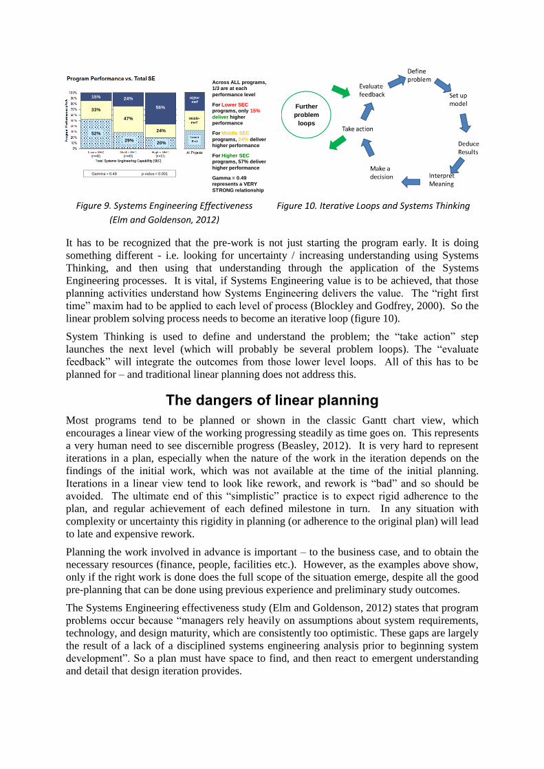
There is plenty of evidence that Systems Engineering adds value (Honour, 2013). The recent
survey of Systems Engineering effectiveness (Elm and Goldenson, 2012) shows an
interesting perspective on value; doing better Systems Engineering increases the probability
of success. This result is emphasized when the complexity of the project is taken into
account, where the difference in benefit between lower and higher Systems Engineering
capability becomes even larger (figure 9).
Is it understood how System Engineering has achieved this impact? In Rolls-Royce the pull
for Systems Engineering comes from the desire to do “pre-work not rework” and the
recognition that the pre-work is valuable because of early detection (Pickard and Nolan,
2013) and prevention of errors.
It has to be recognized that the pre-work is not just starting the program early. It is doing
something different - i.e. looking for uncertainty / increasing understanding using Systems
Thinking, and then using that understanding through the application of the Systems
Engineering processes. It is vital, if Systems Engineering value is to be achieved, that those
planning activities understand how Systems Engineering delivers the value. The “right first
time” maxim had to be applied to each level of process (Blockley and Godfrey, 2000). So the
linear problem solving process needs to become an iterative loop (figure 10).
System Thinking is used to define and understand the problem; the “take action” step
launches the next level (which will probably be several problem loops). The “evaluate
feedback” will integrate the outcomes from those lower level loops. All of this has to be
planned for – and traditional linear planning does not address this.
The dangers of linear planning
Most programs tend to be planned or shown in the classic Gantt chart view, which
encourages a linear view of the working progressing steadily as time goes on. This represents
a very human need to see discernible progress (Beasley, 2012). It is very hard to represent
iterations in a plan, especially when the nature of the work in the iteration depends on the
findings of the initial work, which was not available at the time of the initial planning.
Iterations in a linear view tend to look like rework, and rework is “bad” and so should be
avoided. The ultimate end of this “simplistic” practice is to expect rigid adherence to the
plan, and regular achievement of each defined milestone in turn. In any situation with
complexity or uncertainty this rigidity in planning (or adherence to the original plan) will lead
to late and expensive rework.
Planning the work involved in advance is important – to the business case, and to obtain the
necessary resources (finance, people, facilities etc.). However, as the examples above show,
only if the right work is done does the full scope of the situation emerge, despite all the good
pre-planning that can be done using previous experience and preliminary study outcomes.
The Systems Engineering effectiveness study (Elm and Goldenson, 2012) states that program
problems occur because “managers rely heavily on assumptions about system requirements,
technology, and design maturity, which are consistently too optimistic. These gaps are largely
the result of a lack of a disciplined systems engineering analysis prior to beginning system
development”. So a plan must have space to find, and then react to emergent understanding
and detail that design iteration provides.
Figure 10. Iterative Loops and Systems Thinking
Across ALL programs,
1/3 are at each
performance level
For Lower SEC
programs, only 15%
deliver higher
performance
For Middle SEC
programs, 24% deliver
higher performance
For Higher SEC
programs, 57% deliver
higher performance
Gamma = 0.49
represents a VERY
STRONG relationship
52%
29%20%
33%
47%
24%
15% 24%
56%
Gamma = 0.49 p-value < 0.001
Figure 9. Systems Engineering Effectiveness
(Elm and Goldenson, 2012)
Further
problem
loops

A common feature of many programs is the use of milestones, which are deliveries of
substantive output (designs, hardware, reports etc.). This misses one of the most important
aspects in a plan – the making of timely decisions.
If planning is based on the information that is needed to make the correct decision, then risks
and opportunities can be mitigated in updates to the plan, based on the uncertainty and gaps
in the information available when the decision had to be made. If this approach to flexible
planning was used, built around progressively exploiting the emerging understanding that
comes from the Systems Engineering activities, then the value of Systems Engineering could
be more regularly exploited. This is a critical aspect that needs to be explored as INCOSE
engages with Program Management professional organizations.
Generalization into heuristic and interface with PM
Heuristics are an essential complement to analytics. They are a succinct expression of
principle, taken from the Greek term for guide. They encapsulate the insights that have to be
achieved and practiced before a masterwork can be produced (Rechtin and Maier, 1997). In
Systems Engineering terms they are a readily accessible guide to assist problem solving by
human beings – teaching things to do and approaches / mindsets to avoid.
Based on the arguments above the following new heuristics are suggested to assist with the
proper planning of engineering activities:
1) Showing progress on a linear path is not necessarily good – the path might be in the
wrong direction
2) Recognizing uncertainty is the first step to success – ignoring uncertainty means failure is
actually more likely, but when it happens it will be a surprise. Recognizing uncertainty is
the first step to certainty
3) You don’t make a project cheaper by not doing things; you make it cheaper by doing
more of the right things.
4) The customer may well not be right, but their position is valid from their (current) point
of view and should be respected
Conclusions
A number of examples have been given where to show where project pressure to avoid
missing milestones and keep costs down lead to bad behavior – linear planning and a
tendency to jump to component solutions and avoid valuing the identification and
management of uncertainty.
The purpose of Systems Engineering is to improve the probability of a successful outcome to
a complex/messy problem. It does this by looking for understanding of the problem, and
using that understanding to inform the drive for definition of a solution.
To realize that value there are two essentials
1) That discovering uncertainty is the first step towards certainty. So uncertainty must
be embraced – hence “yes” can often be the wrong answer
2) Plans must include activities to find the uncertainty, but far more importantly they
must be agile enough (and non-linear enough) to react to the uncertainties discovered.
These principles must be “front and center” in discussion between Systems Engineers and
Program Managers.
References Beasley, R. 2012, The Barriers to Systems Thinking, Proceedings of the 22nd international Symposium
of the International Council on Systems Engineering, Rome, Italy
Haskins, C, 2011, Systems Engineering Handbook: A Guide for System Life Cycle Processes and
Activities. Version 3.2.2 Revised by M. Krueger, D. Walden, and R. D. Hamelin. INCOSE-TP-
2003-002-03.2.2, San Diego, CA (US): INCOSE,
Conklin, J, 2006, Wicked Problems and Social Complexity, from Dialogue Mapping: Building Shared Understanding of Wicked Problems, Wiley. Also see the Cognexus Institute website, http://www.cognexus.org
Scheithauer, D. and Forsberg, K., 2013, V-Model Views, Proceedings of the 23rd International Symposium of the International Council on Systems Engineering, Philadelphia, PA, USA.
Pickard, A., Nolan, A., and Beasley, R., 2010, Certainty, Risk and Gambling in the Development of
complex Systems, Proceedings of the 20th International Symposium of the International
Council on Systems Engineering, Chicago, Il, USA.
Rechtin, E. and Maier, M.W., 1997, The Art of Systems Architecting, CRC Press LLC, ISBN 0-8493-
7836-2
Gasser, L., 2008, Functional Durability Over System's Life Span, Proceedings of the 18th annual
International Symposium of the International Council on Systems Engineering, INCOSE 2008
Gilb, T., 2007, Some Powerful Systems Engineering Heuristics, Proceedings of the 17th Annual
International Symposium of the International Council on Systems Engineering, INCOSE 2007
Valerdi, R., 2010, Heuristics for Systems Engineering Cost Estimation, 14th Annual PSM Users' Group
Conference
Nolan, A., Abrahão, S., Clements, P. and Pickard, A. 2011, “Requirements Uncertainty in a Software
Product Line”, 15th International Software Product Line Conference August 22-26, 2011,
Munich, Germany
Gegg, S., 1997, Private Communication, Rolls-Royce
Burns, D., 2013, How can Systems Engineering Enable Innovation and Game-Changing Products?
Keynote presentation, International Council on Systems Engineering (INCOSE) Great Lakes
Regional Conference 2013, West Lafayette, Indiana
Strong, K., Ringer, R. and Taylor, S. 2001, THE* Rules of Stakeholder Satisfaction (*Timeliness,
Honesty, Empathy), Journal of Business Ethics, Vol. 32, Issue 3, pp 219 – 230
McRee, J., 2012 Developing Client Empathy: How Designers can Balance User and Stakeholder
Interests, EffectiveUI, Inc., DCEWP120675,
http://www.effectiveui.com/downloads/publications/EffectiveUI_White_Paper_Developing
_Client_Empathy.pdf
Checkland, P. and Poulter, J. 2007, Learning for Action – A short definitive account of Soft Systems
Methodology and its uses for Practioners, Teachers and Students, John Wiley and sons
Limited, ISBN 978-0-470-02554-3 (PB)
Pless, N. and Maak, T., 2005, Relational Intelligence for leading responsibly in a connected world,
Academy of Management 2005 Annual Meeting,: A New Vision for Management in the 21st
Century, AOM 2005, Honolulu, Hawaii
Blockley, D. and Godfrey, P., 2000, Doing It Differently, Systems for Rethinking Construction, Thomas
Telford, London
Honour, E., 2013 Systems Engineering Return on Investment, PhD thesis, accessible at
http://www.hcode.com/seroi/index.html (accessed 30 October 2013)
Elm, J., & Goldenson, D., 2012, The Business Case for Systems Engineering Study: Results of the
Systems Engineering Effectiveness Survey (CMU/SEI-2012-SR-009). Retrieved October 30,
2013, from the Software Engineering Institute, Carnegie Mellon University website:
http://resources.sei.cmu.edu/library/asset-view.cfm?AssetID=34061
Nolan, A. and Pickard, A., 2013, Reducing Scrap and Rework, Proceedings of the 23rd International
Symposium of the International Council on Systems Engineering, Philadelphia, PA, USA.
Biography
Richard Beasley joined Rolls-Royce in 1986 with a Physics Degree
from Bristol University. He got MSc in Gas Turbine Engineering from
Cranfield University during early career work on Installation
Aerodynamics, Life Cycle Cost, and aspects of designing products for
Aftermarket/Service. He is now the Global Chief of Systems
Engineering, and in 2011 was made a Rolls-Royce Associate Fellow in
Systems Engineering. He was part of the BKCASE SEBoK author
team, and is President-elect for the UK INCOSE Chapter (assuming presidency in November
2014). He is a Chartered Engineer, Fellow of the Royal Aeronautical Society, and a Visiting
Fellow to the Systems Centre at Bristol University.
Andrew Nolan joined Rolls-Royce in 1989 after completing a degree at
Sheffield University. He is the Chief of Software Improvement for
Rolls-Royce based in the UK. He is a Fellow of the British Computer
Society and a chartered Engineer in software engineering. Andrew has
spent over a decade managing large scale software projects as well as a
decade improving the way Rolls-Royce manages projects.
Andrew Pickard joined Rolls-Royce in 1977 after completing a Ph.D. at
Cambridge University in Fatigue and Fracture of Metals and Alloys. He is a
Rolls-Royce Associate Fellow in System Engineering, a Fellow of the
Institute of Materials, Minerals and Mining, a Chartered Engineer and a
member of SAE International and of INCOSE. He is Vice-Chair of the SAE
Aerospace Council and represents Rolls-Royce on the INCOSE Corporate
Advisory Board.