whispergen installation checklist - victron energy
TRANSCRIPT
Personal Power Station
INSTALLATION AND COMMISSIONING MANUAL
Model: PPS16 3000 and 7000 series
Configurations: 12V, 24V Diesel, Kerosene Marine, Land based
Distributed by
Copyright © 2000, 2001 Whisper Tech Ltd. All Rights Reserved.
WHISPERGEN PPS16 Personal Power Station
Installation and Commissioning Manual Revision 270901
This publication or part thereof, may not be reproduced in any form by any method, for any purpose. For
conditions of use and permission to use this document for any form of publication, contact Whisper Tech Ltd.
Whisper Tech Ltd produces documentation in English only.
This document applies to WhisperGen PPS16 units with manufacturing numbers which end in a 6 or a 7.
Whisper Tech Ltd. makes no warranty, either expressed or implied, including but not limited to any implied warranties of merchantability or fitness for a particular purpose, regarding Whisper Tech products and makes
such Whisper Tech products available solely on an “as-is” basis.
Warranties expressed or implied in this publication refer to warranties provided by authorised WhisperGen agents. Warranty for proprietary parts shall be limited to those warranties extended by the supplier of those
parts.
In no event shall Whisper Tech Ltd. be liable to anyone for special, collateral, incidental, or consequential damages in connection with or arising out of purchase or use of Whisper Tech products. The sole and
exclusive liability of Whisper Tech Ltd., regardless of the form of action, shall not exceed the purchase price of the Whisper Tech products described herein.
Whisper Tech Ltd. reserves the right to revise and improve its products as it sees fit. This publication
describes the state of this product at the time of its publication and may not reflect the product at all times in the past and the future.
Patents granted and pending worldwide.
Whisper Tech Limited, WhisperGen,
Personal Power Station, and WhisperGen Personal Power Station are trademarks of Whisper Tech Limited.
Printed in New Zealand.
Distributed by: Victron Energie B.V.
de Paal 35 1351 JG Almere-Haven
The Netherlands
www.victronenergy.com
Telephone: +31-36-535 9700 Fax: +31-36-535 9740
E-mail: [email protected]
CCCOOONNNTTTEEENNNTTTSSS
IIINNNSSSTTTAAALLLLLLAAATTTIIIOOONNN
Page
Introduction Installation checklist 1. Transporting the WhisperGen ......................................................................... 1 2. Unpacking the WhisperGen.............................................................................. 1 3. Mounting the WhisperGen ................................................................................ 1 4. Pressurising the WhisperGen.......................................................................... 4 5. Fitting the exhaust heat exchanger ............................................................... 5 6. Plumbing the coolant circuits for the WhisperGen .................................. 6 The primary coolant circuit ........................................................................................ 6 The secondary coolant circuit.................................................................................... 6 Plumbing the primary coolant circuit.......................................................................... 9 Plumbing the secondary coolant circuit – marine systems ...................................... 10 7. Setting up the battery and control system ................................................ 11 Mounting the control panel ...................................................................................... 12 Connecting the battery ............................................................................................ 14 Control system connection points............................................................................ 15 8. Filling and bleeding the coolant circuits.................................................... 17 9. Setting up combined heating and battery charging............................... 19 Setting up hot water heating.................................................................................... 19 Setting up space heaters......................................................................................... 19 10. Setting up the fuel system ............................................................................. 20 Bleeding the fuel system ......................................................................................... 21 11. Setting up the exhaust system..................................................................... 23 Fresh water flushing of the exhaust heat exchanger ............................................... 24
CCCOOOMMMMMMIIISSSSSSIIIOOONNNIIINNNGGG
AAAPPPPPPEEENNNDDDIIICCCEEESSS
Page Checklist for commissioning 12. The control panel user settings ................................................................... 27 13. Battery settings ................................................................................................. 27 14. WhisperGen check ........................................................................................... 29 15. Monitoring the WhisperGen using the control panel ........................... 29 16. Monitoring the WhisperGen using a computer ...................................... 30 17. Running the WhisperGen for the first time .............................................. 31 18. Heat dump test ................................................................................................... 32 19. User selectable function testing .................................................................. 33 20. Full power operating parameters ................................................................ 34 21. Completing commissioning and filling out the checklist ................... 35 Appendix A: Recommended components for the coolant circuits Appendix B: Battery specifications Appendix C: Recommended circuit breaker
LLLIIISSSTTT OOOFFF FFFIIIGGGUUURRREEESSS Figure 1: Minimum clearances, services layout, and mounting bolts ...... 2 Figure 2: Primary coolant circuit – series ....................................................... 7 Figure 3: Primary coolant circuit – parallel ..................................................... 8 Figure 4: Plumbing the secondary coolant circuit – marine systems.......... 10 Figure 5: Setting up the battery ...................................................................... 11 Figure 6: The control panel.............................................................................. 13 Figure 7: Wiring diagram.................................................................................. 16 Figure 8: Fuel pump and fuel line installation.............................................. 22 Figure 9: Exhaust piping for marine and land based systems................. 25 Figure 10: Micromon MO screen ...................................................................... 31
WhisperGen PPS16 Installation and Commissioning Manual Rev: 080801
IIINNNTTTRRROOODDDUUUCCCTTTIIIOOONNN
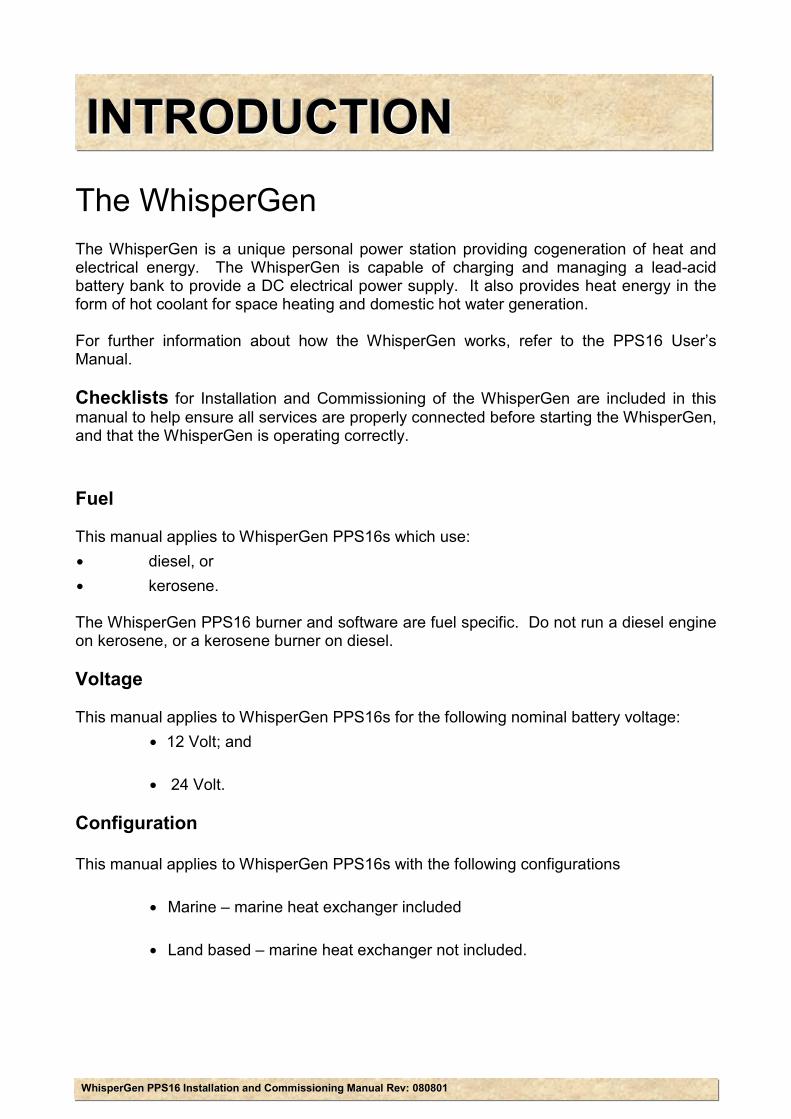
The WhisperGen The WhisperGen is a unique personal power station providing cogeneration of heat and electrical energy. The WhisperGen is capable of charging and managing a lead-acid battery bank to provide a DC electrical power supply. It also provides heat energy in the form of hot coolant for space heating and domestic hot water generation. For further information about how the WhisperGen works, refer to the PPS16 User’s Manual. Checklists for Installation and Commissioning of the WhisperGen are included in this manual to help ensure all services are properly connected before starting the WhisperGen, and that the WhisperGen is operating correctly. Fuel This manual applies to WhisperGen PPS16s which use: ∙ diesel, or ∙ kerosene. The WhisperGen PPS16 burner and software are fuel specific. Do not run a diesel engine on kerosene, or a kerosene burner on diesel. Voltage This manual applies to WhisperGen PPS16s for the following nominal battery voltage: ∙ 12 Volt; and ∙ 24 Volt. Configuration This manual applies to WhisperGen PPS16s with the following configurations ∙ Marine – marine heat exchanger included ∙ Land based – marine heat exchanger not included.
WhisperGen PPS16 Installation and Commissioning Manual Rev: 080801 Installation Checklist 1
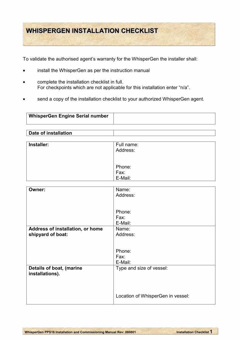
WWWHHHIIISSSPPPEEERRRGGGEEENNN IIINNNSSSTTTAAALLLLLLAAATTTIIIOOONNN CCCHHHEEECCCKKKLLLIIISSSTTT To validate the authorised agent’s warranty for the WhisperGen the installer shall: • install the WhisperGen as per the instruction manual • complete the installation checklist in full.
For checkpoints which are not applicable for this installation enter “n/a”.
• send a copy of the installation checklist to your authorized WhisperGen agent.
WhisperGen Engine Serial number
Date of installation
Installer:
Full name: Address: Phone: Fax: E-Mail:
Owner: Name:
Address: Phone: Fax: E-Mail:
Address of installation, or home shipyard of boat:
Name: Address: Phone: Fax: E-Mail:
Details of boat, (marine installations).
Type and size of vessel: Location of WhisperGen in vessel:
WhisperGen PPS16 Installation and Commissioning Manual Rev: 080801 Installation Checklist 2
Before you install the WhisperGen Read and understand the PPS16 User’s
manual.
Attend the WhisperGen installation course. Read, understand, and comply with the
relevant local authority regulations which apply to this installation.
Read, understand and comply with the Recreational Craft Directive 94/25/EC, issued by the Council of the European Community.
Read the Enable Starts warning.
Page Task Details Complete ( )
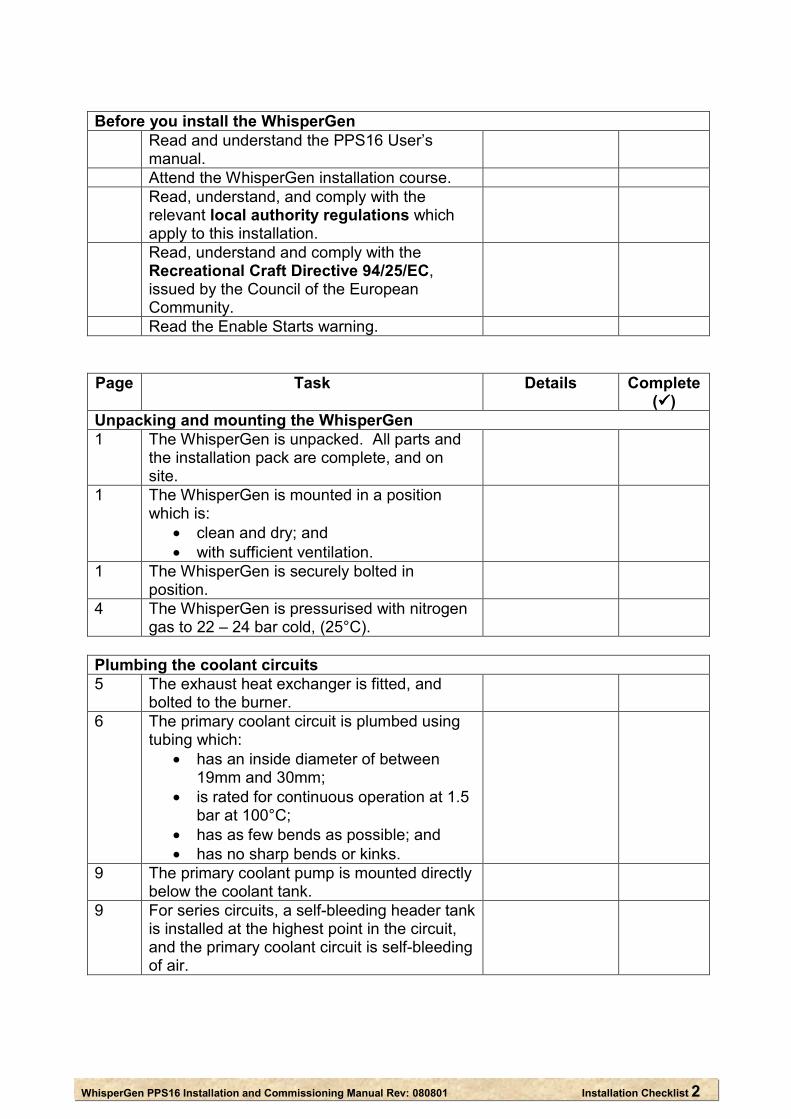
Unpacking and mounting the WhisperGen 1 The WhisperGen is unpacked. All parts and
the installation pack are complete, and on site.
1 The WhisperGen is mounted in a position which is:
• clean and dry; and • with sufficient ventilation.
1 The WhisperGen is securely bolted in position.
4 The WhisperGen is pressurised with nitrogen gas to 22 – 24 bar cold, (25°C).
Plumbing the coolant circuits 5 The exhaust heat exchanger is fitted, and
bolted to the burner.
6 The primary coolant circuit is plumbed using tubing which:
• has an inside diameter of between 19mm and 30mm;
• is rated for continuous operation at 1.5 bar at 100°C;
• has as few bends as possible; and • has no sharp bends or kinks.
9 The primary coolant pump is mounted directly below the coolant tank.
9 For series circuits, a self-bleeding header tank is installed at the highest point in the circuit, and the primary coolant circuit is self-bleeding of air.
WhisperGen PPS16 Installation and Commissioning Manual Rev: 080801 Installation Checklist 3
Page Task Details
Complete ( )
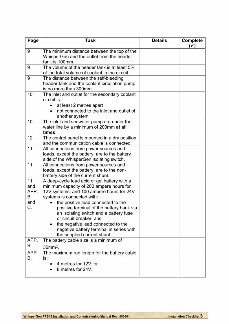
9 The minimum distance between the top of the WhisperGen and the outlet from the header tank is 100mm.
9 The volume of the header tank is at least 5% of the total volume of coolant in the circuit.
9 The distance between the self-bleeding header tank and the coolant circulation pump is no more than 300mm.
10 The inlet and outlet for the secondary coolant circuit is:
• at least 2 metres apart • not connected to the inlet and outlet of
another system
10 The inlet and seawater pump are under the water line by a minimum of 200mm at all times.
12 The control panel is mounted in a dry position and the communication cable is connected.
11 All connections from power sources and loads, except the battery, are to the battery side of the WhisperGen isolating switch.
11 All connections from power sources and loads, except the battery, are to the non-battery side of the current shunt.
11 and APP. B and C.
A deep-cycle lead acid or gel battery with a minimum capacity of 200 ampere hours for 12V systems; and 100 ampere hours for 24V systems is connected with:
• the positive lead connected to the positive terminal of the battery bank via an isolating switch and a battery fuse or circuit breaker; and
• the negative lead connected to the negative battery terminal in series with the supplied current shunt.
APP. B
The battery cable size is a minimum of 35mm².
APP B.
The maximum run length for the battery cable is:
• 4 metres for 12V; or • 8 metres for 24V.
.
WhisperGen PPS16 Installation and Commissioning Manual Rev: 080801 Installation Checklist 4
Page Task Details
Complete ( )
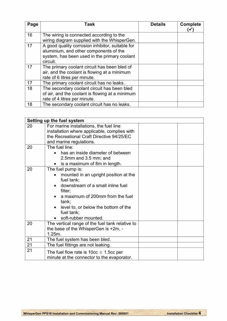
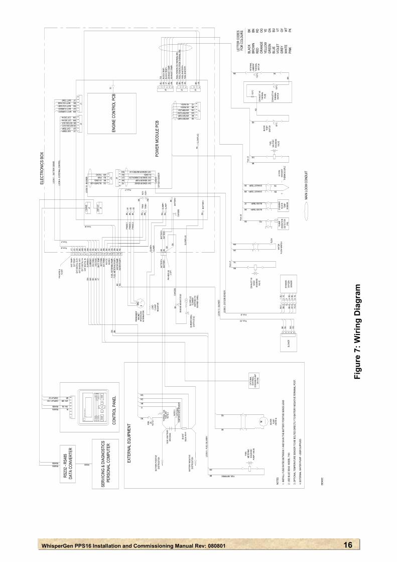
16 The wiring is connected according to the wiring diagram supplied with the WhisperGen.
17 A good quality corrosion inhibitor, suitable for aluminium, and other components of the system, has been used in the primary coolant circuit.
17 The primary coolant circuit has been bled of air, and the coolant is flowing at a minimum rate of 6 litres per minute.
17 The primary coolant circuit has no leaks. 18 The secondary coolant circuit has been bled
of air, and the coolant is flowing at a minimum rate of 4 litres per minute.
18 The secondary coolant circuit has no leaks.
Setting up the fuel system 20 For marine installations, the fuel line
installation where applicable, complies with the Recreational Craft Directive 94/25/EC and marine regulations.
20 The fuel line: • has an inside diameter of between
2.5mm and 3.5 mm; and • is a maximum of 8m in length.
20 The fuel pump is: • mounted in an upright position at the
fuel tank; • downstream of a small inline fuel
filter; • a maximum of 200mm from the fuel
tank; • level to, or below the bottom of the
fuel tank; • soft-rubber mounted.
20 The vertical range of the fuel tank relative to the base of the WhisperGen is +2m, -1.25m.
21 The fuel system has been bled. 21 The fuel fittings are not leaking. 21 The fuel flow rate is 10cc ± 1.5cc per
minute at the connector to the evaporator.
WhisperGen PPS16 Installation and Commissioning Manual Rev: 080801 Installation Checklist 5
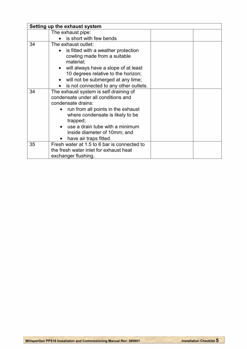
Setting up the exhaust system The exhaust pipe:
• is short with few bends
34 The exhaust outlet: • is fitted with a weather protection
cowling made from a suitable material;
• will always have a slope of at least 10 degrees relative to the horizon;
• will not be submerged at any time; • is not connected to any other outlets.
34 The exhaust system is self draining of condensate under all conditions and condensate drains:
• run from all points in the exhaust where condensate is likely to be trapped;
• use a drain tube with a minimum inside diameter of 10mm; and
• have air traps fitted.
35 Fresh water at 1.5 to 6 bar is connected to the fresh water inlet for exhaust heat exchanger flushing.
WhisperGen PPS16 Installation and Commissioning Manual Rev: 080801 1
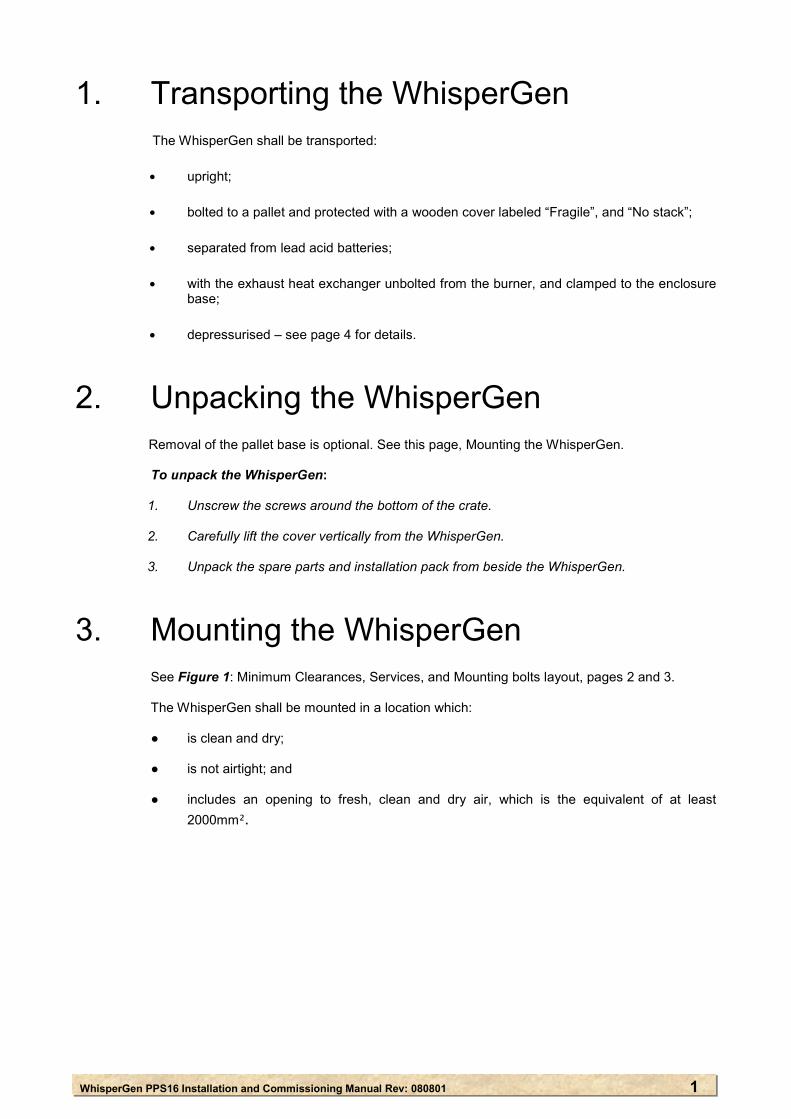
1. Transporting the WhisperGen
The WhisperGen shall be transported: ∙ upright; ∙ bolted to a pallet and protected with a wooden cover labeled “Fragile”, and “No stack”; ∙ separated from lead acid batteries;
∙ with the exhaust heat exchanger unbolted from the burner, and clamped to the enclosure
base; ∙ depressurised – see page 4 for details.
2. Unpacking the WhisperGen
Removal of the pallet base is optional. See this page, Mounting the WhisperGen. To unpack the WhisperGen:
1. Unscrew the screws around the bottom of the crate. 2. Carefully lift the cover vertically from the WhisperGen. 3. Unpack the spare parts and installation pack from beside the WhisperGen.
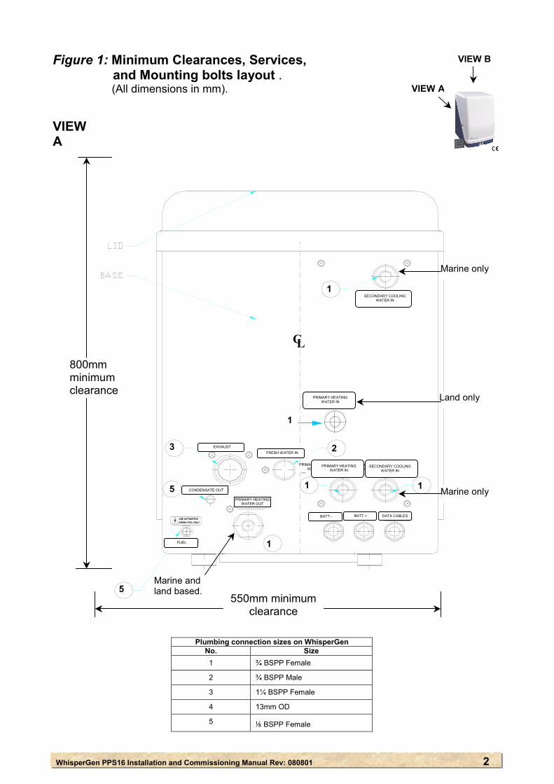
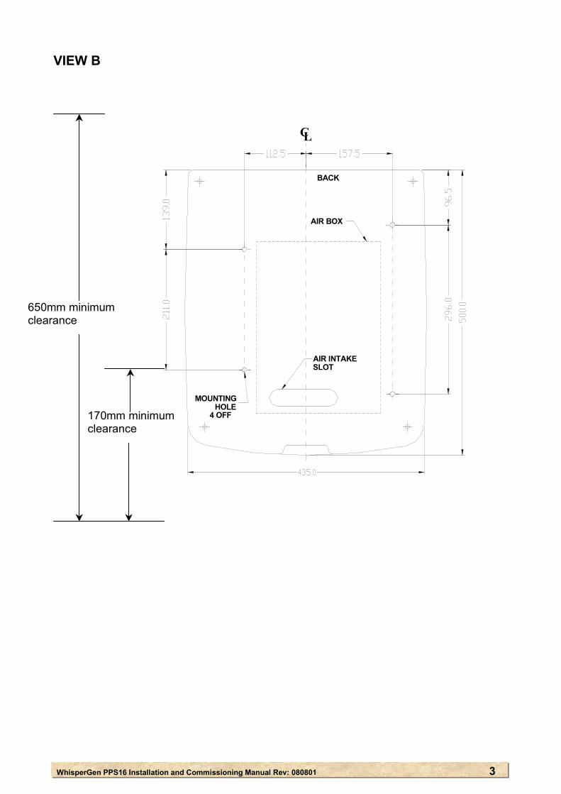
3. Mounting the WhisperGen See Figure 1: Minimum Clearances, Services, and Mounting bolts layout, pages 2 and 3. The WhisperGen shall be mounted in a location which:
● is clean and dry; ● is not airtight; and ● includes an opening to fresh, clean and dry air, which is the equivalent of at least
2000mm².
WhisperGen PPS16 Installation and Commissionin
FUEL
BATT −−
PRIMARY HEATINGWATER IN WATER OUT
WATER IN
1
1 1
1
23
4
5
LC
Figure 1: Minimum Clearances, Services, and Mounting bolts layout . (All dimensions in mm). VIEW A
Plumbing No. 1
2
3
4
5
VIEW B
VIEW A
SECONDARY COOLING WATER OUT
PRIMARY HEATING WATER IN
PRIMARY HEATING WATER OUT
SECONDARY COOLING WATER IN
SECONDARY COOLING WATER IN
PRIMARY HEATING WATER IN
CONDENSATE OUT
EXHAUST FRESH WATER IN
BATT - BATT +
FUEL
DATA CABLESDATA CABLES
800mm minimum clearance
5
1
1 1
23
1
5
5
Marine only
Marine only
Marine and land based.
PRIMARY HEATING WATER IN
Land only
1
50mm minimumclearance
g Manual Rev: 080801
connection sizes on WhispSize
¾ BSPP Female
¾ BSPP Male
1¼ BSPP Female
13mm OD
⅛ BSPP Female
erGen
2
WhisperGen PPS16 Installation and Commissioning Manual Rev: 080801 3
VIEW B
BACK
AIR BOX
LC
MOUNTINGHOLE
4 OFF
AIR INTAKE SLOT
170mm minimum clearance
650mm minimum clearance
WhisperGen PPS16 Installation and Commissioning Manual Rev: 080801 4
4. Pressurising the WhisperGen Warning: The WhisperGen is a pressurised device. Contact your distributor if disassembly of the core
engine is required. Warning: The maximum pressure is limited by a pressure relief valve. This valve shall not be adjusted. A
pressure relief valve is set at the factory, and any adjustment voids all warranties and can result in an unsafe and/or unreliable machine.
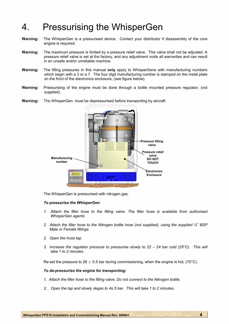
Warning: The filling pressures in this manual only apply to WhisperGens with manufacturing numbers
which begin with a 3 or a 7. The four digit manufacturing number is stamped on the metal plate on the front of the electronics enclosure, (see figure below).
Warning: Pressurising of the engine must be done through a bottle mounted pressure regulator, (not
supplied). Warning: The WhisperGen must be depressurised before transporting by aircraft. The WhisperGen is pressurised with nitrogen gas. To pressurise the WhisperGen:
1. Attach the filler hose to the filling valve. The filler hose is available from authorised WhisperGen agents
2. Attach the filler hose to the Nitrogen bottle hose (not supplied), using the supplied ¼” BSP
Male or Female fittings.
2. Open the hose tap. 3. Increase the regulator pressure to pressurise slowly to 22 – 24 bar cold (25°C). This will
take 1 to 2 minutes. Re-set the pressure to 28 ± 0.5 bar during commissioning, when the engine is hot, (70°C).
To de-pressurise the engine for transporting: 1. Attach the filler hose to the filling valve. Do not connect to the Nitrogen bottle.
2. Open the tap and slowly degas to 4±.5 bar. This will take 1 to 2 minutes.
Pressure relief valve
DO NOT TOUCH
Pressure filling valve
ElectronicsEnclosure
7096
Manufacturing number

WhisperGen PPS16 Installation and Commissioning Manual Rev: 080801 5
5. Fitting the exhaust heat exchanger The exhaust heat exchanger is de-coupled from the burner during shipping. To fit the exhaust heat exchanger:
1. Unbolt and remove the clamp holding the exhaust heat exchanger to the enclosure base.
2. Refit the bolt to the exhaust heat exchanger.
3. Fit the supplied gasket between the exhaust heat exchanger and the burner.
4. Firmly bolt the exhaust heat exchanger to the burner using the supplied nuts and washers.
WhisperGen PPS16 Installation and Commissioning Manual Rev: 080801 6
6. Plumbing the coolant circuits for the WhisperGen
Warning: A corrosion inhibitor shall be used in the primary coolant circuit because the engine is largely
manufactured from aluminium alloy. See also section 8: Filling and bleeding the coolant circuits. The WhisperGen has three fluid circuits: ● the primary coolant circuit; • the secondary coolant circuit; and • the flushing valve fresh water circuit. 6.1 The primary coolant circuit The primary coolant circuit recovers heat from the WhisperGen. The coolant flows directly
through the engine. Heat is extracted from the primary coolant water by various optional heating devices, such as radiators and boilers, and either a water to water heat exchanger for marine systems or an external fan-radiator for land-based systems.
Primary coolant circuits for WhisperGens with a manufacturing number ending in 7 can be
either series or parallel. Primary coolant circuits for WhisperGens with a manufacturing number ending in 6 shall
always be in series with the pump.
A series circuit (see Figure 3: Primary coolant circuit - series), is the preferred option because: • it ensures that primary coolant is always flowing through all parts of the circuit; and ● it is self-bleeding of air. A parallel circuit (see Figure 4: Primary coolant circuit - parallel) is not recommended because: ● it causes inconsistencies in the heating system; and ● it does not self-bleed. Air bleed valves are required at all high points in the parallel
system.
6.2 The secondary coolant circuit The secondary coolant circuit is used for rejecting excess heat. Heat is dumped into
either: • a marine seawater heat exchanger for marine systems; or • a radiator, (liquid to air heat exchanger) with a fan for land based systems.
Marine versions of the WhisperGen are fitted with a titanium plate seawater heat
exchanger. Land based systems are not supplied with a primary radiator. A radiator which is
appropriate for the application and environment should be selected.
WhisperGen PPS16 Installation and Commissioning Manual Rev: 080801 7
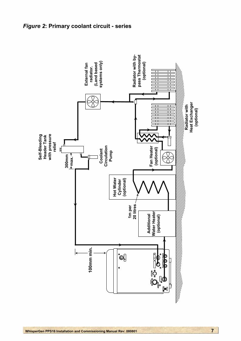
Figure 2: Primary coolant circuit - series
Add
ition
al
Wat
er H
eate
r (o
ptio
nal)
Hot
Wat
er
Cyl
inde
r (o
ptio
nal)
Rad
iato
r with
H
eat E
xcha
nger
(o
ptio
nal)
Rad
iato
r with
by-
pass
The
rmos
tat
(opt
iona
l)
Self-
Ble
edin
g H
eade
r Tan
k
with
pre
ssur
e re
lief
Coo
lant
C
ircul
atio
n Pu
mp
100m
m m
in.
1m p
er
20 li
tres
300m
m
max
.
Fan
Hea
ter
(opt
iona
l)
FUEL
Exte
rnal
fan
radi
ator
. (L
and
base
d sy
stem
s on
ly)
WhisperGen PPS16 Installation and Commissioning Manual Rev: 080801 8
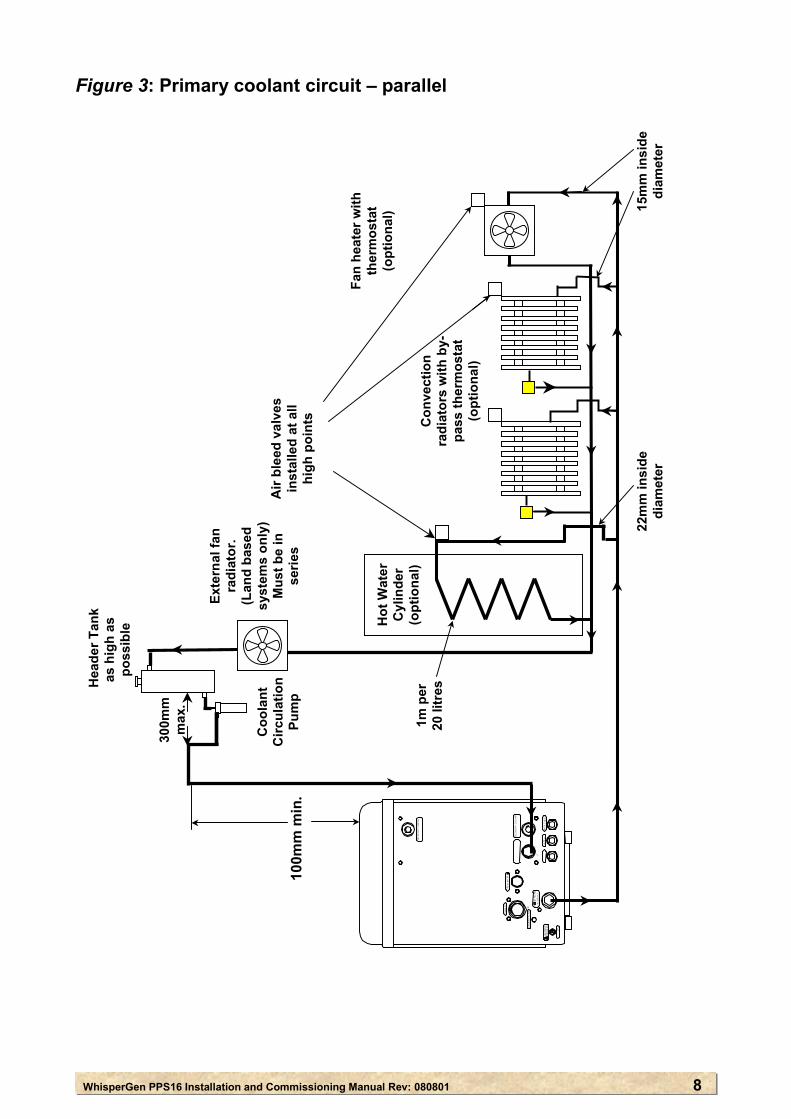
Figure 3: Primary coolant circuit – parallel
Hot
Wat
er
Cyl
inde
r (o
ptio
nal)
Con
vect
ion
radi
ator
s w
ith b
y-pa
ss th
erm
osta
t (o
ptio
nal)
Hea
der T
ank
as
hig
h as
po
ssib
le
Coo
lant
C
ircul
atio
n Pu
mp
10
0mm
min
.
1m p
er
20 li
tres
Fan
heat
er w
ith
ther
mos
tat
(opt
iona
l)
Air
blee
d va
lves
in
stal
led
at a
ll hi
gh p
oint
s
15m
m in
side
di
amet
er
22m
m in
side
di
amet
er
300m
m
max
.
FUEL
Exte
rnal
fan
radi
ator
. (L
and
base
d sy
stem
s on
ly)
Mus
t be
in
serie
s
WhisperGen PPS16 Installation and Commissioning Manual Rev: 080801 9
6.3 Plumbing the primary coolant circuit
See Figure 2: WhisperGen services layout, Figure 3: Primary coolant circuit – series; and Figure 4: Primary coolant circuit - parallel. The WhisperGen primary inlet and outlet connections are ISO Rp ¾ BSP female threads. They are on the back of the WhisperGen enclosure, marked “PRIMARY HEATING IN” and ‘PRIMARY HEATING OUT”. The primary circuit shall have a pressure relief system on top of the header tank, set at a maximum of 1 bar. The tubing for the primary coolant circuit shall:
● have an inside diameter of between 19mm (¾”) and 30mm (1¾”); ● be rated for continuous operation at 100°C at 1 bar. ● be as short as possible, with a maximum length of 25 metres; ● have as few bends as possible with no sharp bends or kinks; and ● be clean and free of debris. The primary coolant pump shall be mounted directly below the coolant tank. For series circuits:
● a self-bleeding header tank shall be installed at the highest point in the circuit. The
volume of the header tank shall be at least 5% of the total volume of coolant in the circuit. This will allow for thermal expansion of the coolant. Allow approximately 2 litres for the WhisperGen.
● the distance between the self-bleeding header tank and the primary coolant pump
shall be a maximum of 300mm; and ● the minimum distance between the top of the WhisperGen and the outlet from the
self-bleeding header tank is 100mm. For parallel circuits: ● air bleed valves shall be installed at all high points; ● the minimum distance between the top of the WhisperGen and the outlet from the
header tank is 100mm; and ● the tubing which goes through the hot water cylinder shall have an inside diameter
of 22mm. The rest of the plumbing shall use tubing with an inside diameter of 15mm. It is important that the flow restriction of the tubing which goes through the hot water cylinder is less than the other parallel heating devices.
WhisperGen PPS16 Installation and Commissioning Manual R
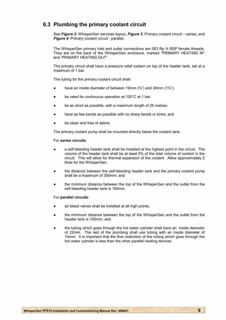
6.4 Plumbing the secondary coolant circuit – marine systems
See Figure 5: Plumbing the secondary coolant circuit. Warning: The inlet and outlet for the secondary coolant circuit shall not be connected to the inlet or outlet
of another system. Warning: The inlet and the seawater pump shall be under the water line by a minimum of 200mm at all
times. Warning: The inlet and outlet for the secondary coolant circuit shall be at least 2 metres apart.
Figure 4: Plumbing the secondary coolant circuit – marine systems
FUEL BATT −−
PRIMARY HEATING WATER IN WATER OUT
WATER IN
2Seawater
Level Seawater Pump
750mmmax.
2m min. Outlet
Inle
Hull of boat
00mm min.
ev: 080801 10
t
WhisperGen PPS16 Installation and Commissioning Manu
7. Setting up the battery and control system
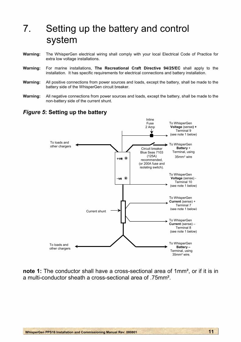
Warning: The WhisperGen electrical wiring shall comply with your local Electrical Code of Practice for
extra low voltage installations. Warning: For marine installations, The Recreational Craft Directive 94/25/EC shall apply to the
installation. It has specific requirements for electrical connections and battery installation. Warning: All positive connections from power sources and loads, except the battery, shall be made to the
battery side of the WhisperGen circuit breaker. Warning: All negative connections from power sources and loads, except the battery, shall be made to the
non-battery side of the current shunt. Figure 5: Setting up the battery
note 1: The conductor shall have a a multi-conductor sheath a cross-sec
To loads and other chargers
To WhisperGen Voltage (sense) +
Terminal 9 (see note 1 below)
To loads and other chargers
Inline Fuse
2 Amp
Circuit breaker Blue Seas 7103
(125A)
To WhisperGen Battery +
Terminal, using
Batterya
ct
35mm² wire
TC
)
recommended, (or 200A fuse and isolating switch).
To WhisperGen Voltage (sense) -
Terminal 10 (see note 1 below)
----ve ve ve ve ◉
Current shunt
l Rev: 080801
ross-sectional area oional area of .75mm².
T
TC
o WhisperGen urrent (sense) +
Terminal 7 (see note 1 below
+ +ve+ve+ve+ve ◉
11
f 1mm², or if it is in
o WhisperGenBattery –
Terminal, using 35mm² wire.
o WhisperGen urrent (sense) –
Terminal 8 (see note 1 below)
WhisperGen PPS16 Installation and
STANDBY
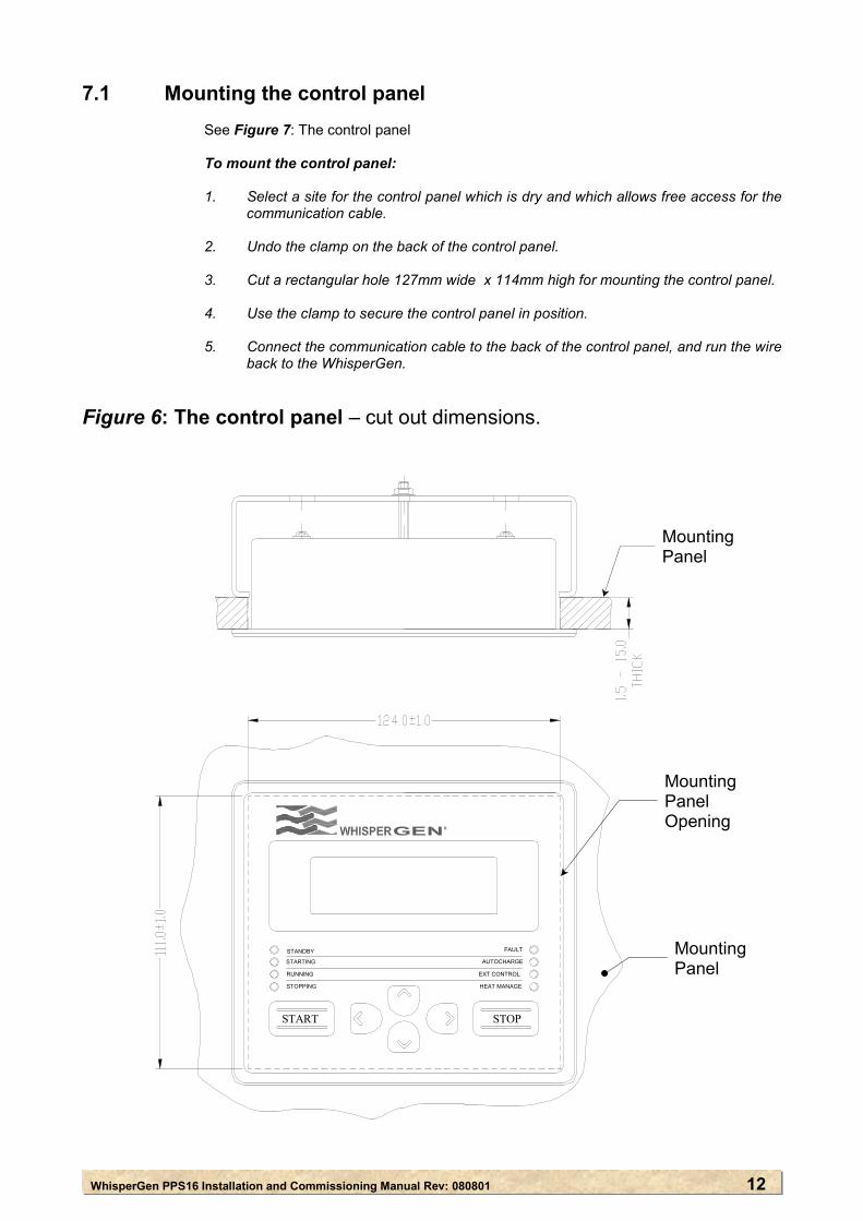
7.1 Mounting the control panel
See Figure 7: The control panel
To mount the control panel: 1. Select a site for the control panel which is dry and which allows free access for the
communication cable. 2. Undo the clamp on the back of the control panel. 3. Cut a rectangular hole 127mm wide x 114mm high for mounting the control panel. 4. Use the clamp to secure the control panel in position. 5. Connect the communication cable to the back of the control panel, and run the wire
back to the WhisperGen.
Figure 6: The control panel – cut out dimensions.
FAULT
AUTOCHARGE
HEAT MANAGE
S P
EXT CONTROL
STOPPING
S ART
STANDBY
STARTING
RUNNING
R
Mounting Panel
Mounting Panel Opening
Mounting Panel
STANDBY
STARTING
RUNNING
STOPPING
FAULT
AUTOCHARGE
EXT CONTROL
HEAT MANAGE
S ART P
TTCommissioning Manual Rev: 080801
TOSTO
12
WhisperGen PPS16 Installation and Commissioning Manual Rev: 080801 13
7.2 Connecting the battery
See Appendix A and Appendix B for recommended components. See Figure 8: Wiring diagram. To connect the battery:
1. Connect the positive lead. This is connected to the positive terminal of the battery
bank via an isolating switch, and a battery fuse or circuit breaker. 2. Connect the negative lead from the battery negative terminal to the current shunt
which is supplied with the WhisperGen. This allows the WhisperGen to monitor all charge and discharge current. Do not
make any other connections to the battery negative terminal or the battery side of the current shunt.
3. Connect the battery sense wiring loom from terminals 7 to 11: ● connect the current shunt + sense wire to terminal 7; ● connect the current shunt – sense wire to terminal 8; ● connect the battery voltage + sense wire to terminal 9; ● connect the battery voltage – sense wire to terminal 10; and ● connect the battery temperature sense wire to terminal 11 and the battery negative terminal.
WhisperGen PPS16 Installation and Commissioning Manual Rev: 080801 14
7.3 Control system connection points
7.3.1 Primary coolant pump The power to the primary coolant pump terminals is supplied directly from
the alternator of the WhisperGen. The pump will continue to run if the WhisperGen is running, and is disconnected from the batteries.
The WhisperGen turns on the water pump when it is started and turns it off
when it is stopped and has cooled down. The primary coolant pump shall be connected to terminals 18- and 19+. See
Figure 8: Wiring diagram. 7.3.2 The Auxiliary DC Output
Warning: The primary coolant pump shall not be connected to terminal 14- and terminal 15+.
Warning: The combined current output from both the Auxiliary Power
Output and the Ext PWM Output, shall not exceed 12A.
The WhisperGen has an auxiliary DC output, at battery voltage, to provide power to any other auxiliary equipment which is required to be switched by the WhisperGen. Auxiliary power is available only when the WhisperGen is starting, running or stopping. The Auxiliary DC output shall be connected to terminals 14- and terminal 15+. See Figure 8: Wiring diagram.
7.3.3 Secondary Coolant Pump Warning: Do not use relays in this circuit.
A DC PWM output from the WhisperGen enables the WhisperGen to control
the operating temperature of the system. It shall be connected to:
● the secondary coolant pump for marine systems; or ● the heat dump fan or land based systems. The PWM output terminals are 12- and 13+ on the wiring block. See Figure 8: Wiring diagram.
7.3.4 External Digital In Warning: Do not apply voltage across these terminals. These inputs allow the WhisperGen to be turned on and off by an external
set of contacts. The contacts can be a switch, thermostat, timer or some other device which starts and stops the WhisperGen. The contacts shall be physical or ‘dry contacts’.
The EXT Digital In input terminals are 5+ and 6- of the wiring block.
See Figure 8: Wiring diagram.
WhisperGen PPS16 Installation and Commissioning Manual Rev: 080801 15
7.3.5 External Digital Out The maximum output current is 100mA. The External Digital Out is a low current, 5V digital output which allows the
WhisperGen to control the temperature of the coolant by switching an optional additional water heater on and off. The output is logic only and cannot drive a relay, but is suitable for digital input to another device.
The EXT Digital Out output terminals are 3+ and 4- of the wiring block. See
Figure 8: Wiring diagram.
7.3.6 External Temperature These terminals are not used. They are 1 and 2 of the wiring block. 7.3.7 Fuel Pump WARNING: Only use the fuel pump supplied with the WhisperGen. The fuel pump is a solenoid-operated piston pump. The speed of operation
of the fuel pump is controlled by the WhisperGen microprocessor. The positive and negative poles of the fuel pump can be swapped.
The arrow on the fuel pump indicates the direction of the fuel flow. The fuel pump shall be wired to terminals 16 and 17 of the wiring block. See
Figure 8: Wiring diagram.
WhisperGen PPS16 Installation and Commissioning Manual Rev: 080801 16
50
1 2 3 4 5 6 7 8 9 10 11 12 13 14
POW
ER M
ODUL
E PC
B1 32 4 5 6
J8
36
J44
51
2
21
J53 4
12
34
56
J1
12
34 2
J95
63
41
J10
12
34
56
J7
VT GY
WHGN
WHGYRDBKVT
LOOM
4 -
EXTE
RNAL
CON
TROL
LOOM
1 -
BAT
TERY
SEN
SE
Ø1 Ø2 Ø3 CLAM
P+CL
AMP-
BATT
ERY+
BATT
ERY-
GLOW
PLUG
LOAD
CLAM
PRE
SIST
OR
EXT
DIGI
TAL
IN+
EXT
DIGI
TAL
OUT-
BATT
ERY-
BATT
ERY+
BK BK
BK
BK
EXT
DIGI
TAL
IN-
CURR
ENT+
CURR
ENT-
VOLT
AGE+
VOLT
AGE-
BATT
TEM
PEX
T PW
M-
EXT
PWM+
AUX
DC-
AUXD
C+
LOOM
10
- BLO
WER
LOOM
9
WHBUBKOG
CONT
ROL P
ANEL
CHAS
SIS
BK
BLOW
ER
0V (GND)BLOWER +24V
PWMTACHO
BATT CURRENT-BATT VOLTAGE+
BATT CURRENT+
BATT VOLTAGE-BATT TEMP
EXT DIG IN+EXT DIG IN-
OXYG
EN
BU YE RD BK YEGY YEBUBKW
H
PHAS
E 1
PHAS
E 2
PHAS
E 3
CLAM
P+CL
AMP-
BATT
ERY+
BATT
ERY-
EXHA
UST
TEMP
+EX
HAUS
T TE
MP-
BLOC
K TE
MP+
BLOC
K TE
MP-
FID
FUEL
POW
ER (F
ROM
THE
RMAL
SW
)FU
EL P
OWER
(TO
THER
MAL S
W)
BU BK VT BU WH RD BN
RDBKWHGNBNYE
WATER PUMP+WATER PUMP-WATER FLOW+WATERFLOW-
HX WASH -HX WASH+
SHUT
OFF
BK
OG
SOLE
NOID
SOLE
NOID
PUMP
FLOW
-SW
ITCH
WAT
ER
WAS
H
WAT
ER
FLOW
BK
RD
YE
GN
BN
WH
THER
MAL
SWIT
CH
BN
150°
C
EXHAUST TEMP-
EXHAUST TEMP+BN
BU
FID
BLOCK TEMP-
BLOCK TEMP+BK
VT
BU
RS485ARS485B
DISPLAY +12VDISPLAY 0V
43
21
BR
WH / BLBL
WH / BR
56
78
SERV
ICIN
G &
DIAG
NOST
ICS
PERS
ONAL
COM
PUTE
R
1
BLOC
KTH
ERM
OCOU
PLE
EXHA
UST
IONI
SATI
ONFL
AME1
DETE
CTOR
(FID
)3
OGWH
1 2BUBK
54
ELEC
TRON
ICS
BOX
SHUN
T
12/2
4 V
BATT
ERY
15
THER
MAL C
/B
MIN
200A
h
FUEL
VALV
E
PK
VALV
E
EXHA
UST
HX
DYNA
MIC
SENS
OR
DATA
CON
VERT
ERRS
232 -
RS4
85
ENGI
NE C
ONTR
OL P
CB
EXHA
UST
HX
SWIT
CHTH
ERMA
LAM
BIEN
TIN
TERN
AL
FUSE
THER
MAL
EXHA
UST
HX
RS485BRS485A RS232
BK BK BK BU BU
PK
BURN
ER S
HELL
EART
H ST
UD
GLOW
PLUG
BK
ENGI
NE M
OUNT
STU
D
OXYG
EN S
ENSO
R
GN
BK
VI
EXTE
RNAL
EQU
IPME
NT
CYLI
NDER
TEMP
SENS
OR
100°
C
100°
C
600A
, 50m
V
125A
, 30V
EXT DIG OUT- BKEXT DIG OUT+ OG
EXT TEMP- GYEXT TEMP+ VT
TEM
PERA
TURE
SEN
SOR
WH
OR WH
GR RD VTBKGYWH
EXT
DIGI
TAL O
UT+
EXT
TEMP
-EX
T TE
MP+
RDBKBNBUBK
BU
PWM
+BN
PWM-
AUX-
AUX+
BK RD
FUEL
SHU
TOFF
+OR
FUEL
SHU
TOFF
-BK
DISP
LAY
J2
COM
MSJ3
VTBKRDWH
GN
RD
FISE 2A
OPTI
ONAL
NO
TE 3
BATT
ERY
POSI
TIVE
DIST
RIBU
TION
BATT
ERY
NEGA
TIVE
DIST
RIBU
TION
NOTE
S:
1. IN
STAL
L FU
SE R
ATED
BET
WEE
N 1
AND
5A IN
THE
BAT
TERY
POS
ITIV
E SE
NCE
LEAD
2. US
E BL
UE S
EAS
MOD
EL 71
03
3. OP
TION
AL T
EMPE
RATU
RE S
ENSO
R TO
BE
BOLT
ED D
IREC
TLY
TO B
ATTE
RY N
EGAT
IVE
TERM
INAL
POS
T.
4. EX
TERN
AL W
ATER
PUM
P - U
SER
SUPP
LIED.
NOTE
2
K-TY
PE
NOTE
1
STA
RTI
NG
STA
RT
STO
PPI
NG
RU
NN
ING
STA
ND
BY
SC
HE
DU
LE
STO
P
AU
TOC
HAR
GE
EXT
CO
NTR
OL
FAU
LT
WAT
ER P
UMP-
WAT
ER P
UMP+
FUEL
MET
ERIN
G PU
MP-
FUEL
MET
ERIN
G PU
MP+
191816 17
PERM
ANEN
T MA
GNET
BR
USHL
ESS
ALTE
RNAT
OR
GLOW
PLUG
EL
EMEN
T EA
RTHE
D TO
BU
RNER
SHE
LL
BK
CHAS
SIS
431 2J6
GNBN
PUM
P / V
ALVE
SOLE
NOID
METE
RING
FUEL
BR
GN
BLOC
KTE
MP.
SWIT
CH 95°C
RD
OPTI
ONAL
EX
TERN
AL
COOL
ING
PUMP
OR
FAN
MAIN
LOO
M CO
NDUI
T
RDBKBNGN
From J10
LOOM
10
- BLO
WER
LOOM
9 -
OXYG
EN S
ENSO
R
From J9
From
J7
From
J8
From
J5
FUEL METERING
From J7
From J6
From J4
From J1
RDBKBNGN
LOOM
6 -
FUEL
DEL
IVER
Y
(NOT
E 4)
RD
BN
BU
BN
YEBKGYBUWH OXY SENSOR HEATER 4.3V
0V (GND)OXY SENSOR COMMON 2.5VOXY SENSOR PUMPOXY SENSOR SENSE
FOR
COL
OURS
BLAC
K
BK
BROW
N
BN
RED
RD
ORAN
GE
OGYE
LLOW
Y
EGR
EEN
G
NBL
UE
B
UVI
OLET
VT
GREY
GY
WHI
TE
W
TPI
NK
PK
PH H
DFK
502
OFF
PH H
DFK
419
OFF
3MG
M
66
33
5454
221
1
LETT
ER C
ODES
500A
Figu
re 7
: Wiri
ng D
iagr
am
SEN
SE

WhisperGen Installation and Commissioning Manual Rev: 080801 17
8. Filling and bleeding the coolant circuits Warning: A corrosion inhibitor shall be used in the primary cooling circuit because the engine is largely
manufactured from aluminium alloy. A good quality corrosion inhibitor shall be used. Warning: If ethylene glycol, (automotive anti-freeze) is used as the corrosion inhibitor, a minimum of 35%
undiluted glycol to 65% fresh water solution shall be used for the coolant. A higher concentration of glycol may be needed if the coolant system is subject to very low temperatures.
Warning: It is essential that the primary coolant is clean and free from debris. Foreign particles can
obstruct internal coolant passages and damage the WhisperGen. Contaminated circuits shall be fitted with sludge traps upstream of the WhisperGen.
Warning: Anything connected to the AUX DC terminals will be powered up when the primary and/or
secondary coolant circuits are bled. A drain tap allows coolant to be drained from the WhisperGen engine. The drain tap is on the
lower left-hand side of the engine housing, and is accessed through the front cut on the mounting frame. This valve must be closed at all times.
To bleed the primary coolant circuit: 1. Fill the primary coolant circuit header tank with coolant. 2. With the header tank full, slowly unscrew:
● the small bleed valve which is fitted to the top left-hand side of the WhisperGen
exhaust heat exchanger; and ● any other bleed valves fitted to the circuit. 3. Leave the bleed valve(s) open until the coolant begins to dribble out, and then close
immediately. 4. Close the WhisperGen circuit breaker and ensure that text is displayed on the control
panel. Warning: Before continuing with the installation the Enable Starts option in the Installation Menu should
be set to 0 to prevent unintentional starts of the WhisperGen. For further information see the User’s Manual, section 3.
5. Press < on the control panel until the default display is displayed.
6. Press > to display the first item on the Main Menu, the User Menu. 7. Press v to scroll down to the Installation Menu. 8. Press > to display the first item on the Installation Menu.
9. Press v to scroll down to Coolant Bleed. 10. Press > to begin editing the Coolant Bleed setting.
11. Press ^̂̂̂ to select On. The coolant pump will be turned on to bleed the coolant circuit.
12. Continue to fill up the header tank until it will not accept any more coolant. Make sure the
header tank does not run dry.
WhisperGen Installation and Commissioning Manual Rev: 080801 18
13. Make sure that the coolant is flowing at a minimum flow rate of 6 litres per minute. 14. Check the primary coolant circuit for leaks.
15. Open the bleed valves as necessary to remove air from the circuit. To bleed the secondary coolant circuit: 1. Access the Main Menu on the control panel.
2. Press v to scroll down to the Installation Menu.
3. Press > to display the first item on the Installation Menu. 4. Select Coolant Bleed 2. 5. Press > to begin editing the coolant bleed setting.
6. Press ^̂̂̂ to turn the Coolant Bleed 2 function to On. 7. Check that the pump is priming and that seawater is flowing from the outlet.
8. Check that the secondary coolant circuit has a minimum flow rate of 4 litres per minute.
9. Check the secondary coolant circuit for leaks.
The secondary coolant pump will run for 1 hour after being turned on before automatically turning off. It can be turned off, if necessary, at any time, by turning the Coolant Bleed 2 function to Off.
WhisperGen PPS16 Installation and Commissioning Manual Rev: 080801 19
9. Setting up combined heating and battery charging
9.1 Setting up hot water heating
Warning: If a thermostat is used to start the WhisperGen, it shall be set 5°C below the coolant
temperature set point, (refer to the control panel). If the thermostat is set higher than the coolant temperature set point, the WhisperGen will not be able to heat the water in the hot water cylinder/boiler to a high enough temperature to turn the WhisperGen off.
Warning: The hot water cylinder/boiler shall have a heating coil length of 1 metre per 20 litres water
capacity, up to a recommended maximum of 10 metres.
A hot water cylinder/boiler with a minimum 40 litres capacity is recommended. To set up hot water heating: 1. Connect a thermostat to the hot water cylinder, and the External Digital In contacts on
the electronics enclosure. 2. On the control panel, turn External Control to On, and select Mode 2. (Mode 1 can be
used if required).(Refer to the user manual for more information). 3. Set the thermostat at least 5°C below the Temp Setpoint. This is to ensure that the
thermostat will open, and turn the WhisperGen off. 9.2 Setting up space heaters
The heat output (kW) rating of most commercially available space heaters is rated with a room temperature of 20°C and a surface temperature, (coolant temperature), of 80°C. The maximum coolant temperature setting for the WhisperGen is 70°C. To ensure that the full heat capacity from the WhisperGen can be used, the size (heat output), of the heaters shall be 7.2kW. This is equivalent to 6kW at 80°C. Fan heating:
To connect a fan heater:
1. Plumb the primary coolant through the radiator core. 2. Connect the electric fan to a separate room thermostat to turn the fan on and off.
See Figure 3: Primary coolant circuit – series. Convection radiator heating: For convection radiator heaters, which are fitted with a bypass thermostat valve, plumb as for
fan heating. For convection radiator heaters, which are not fitted with bypass thermostat valves, install
an additional heat exchanger and pump, and ensure that the pump is switched by the room thermostat. See Figure 3: Primary coolant circuit – series
Additional heating device:
An additional heating device shall be fitted if the heat supplied by the WhisperGen is not enough to meet the required heat demand. The WhisperGen will control the function of the additional heater and only turn it on as required.
WhisperGen PPS16 Installation and Commissioning Manual Rev: 080801 20
10. Setting up the fuel system Warning: The WhisperGen burner is fuel specific and can operate only on the fuel it has been configured
for. The evaporator at the top of the burner is marked ‘D’ for diesel and ‘K’ for kerosene. Warning: For the diesel burner use only good quality automotive diesel (BS2869: 1988 burner fuel class
D) with the WhisperGen. Do not use other fuel types such as heating oil, petrol, aviation fuel, and LPG.
For the kerosene burner use only good quality automotive kerosene (BS2869: 1988 burner fuel
class C2). Warning: An approved fuel line with an inside diameter of between 2.5mm and 3.5mm shall be used. A
line with a larger inside diameter may cause air/vapour bubbles to form in the fuel line. This may make it difficult to start the burner and may extinguish the flame during operation. The fuel line shall be a maximum of 8m in length. Header or day tanks shall be used for longer runs.
Warning: The distance from the fuel pump and filter to the fuel tank shall be a maximum of 200mm. Warning: For marine installations, the fuel system installation where applicable, shall comply with the
Recreational Craft Directive 94/25/EC, issued by the Council of the European Community. Warning: Bleeding the fuel system will cause water pumps and fans to start. Ensure pumps and coolant
circuits are installed and bled before bleeding the fuel system.
If the fuel line is connected to a fuel tank used by other equipment, draw the fuel supply from a separate outlet.
An ISO Rp ⅛ female fitting is provided on the back of the WhisperGen enclosure for the fuel inlet.
Mount the supplied fuel pump: ∙ upright at the fuel tank outlet; ∙ level to, or below the bottom of the fuel tank; and ∙ on a soft rubber pad to prevent noise transmission. An inline filter shall be fitted between the fuel tank and the fuel pump. To prevent air/vapour bubbles collecting, all changes in height in the fuel line shall be free of
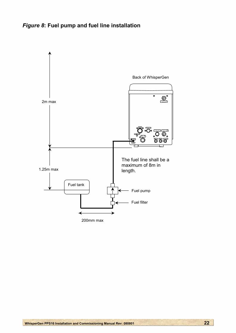
dips or loops. The vertical range of the fuel level in the tank relative to the base of the WhisperGen is +2m, -1.25m, see Figure 9: Fuel pump and fuel line installation. It is recommended that a short length of approved flexible fuel line be installed on each side of the pump to stop the ticking noise being transmitted into the metal fuel line.
WhisperGen PPS16 Installation and Commissioning Manual Rev: 080801 21
10.1 Bleeding the fuel system
At least twice the volume of fuel in the entire fuel line connecting the fuel tank to the burner evaporator, shall be bled. For example, if the fuel line measures 3mm in inner-diameter and 5 metres in length, then a minimum of 70ml of fuel shall be bled.
The default Fuel Bleed function will bleed the system in pulses for 60 minutes. The fuel pump can be stopped at any time by pressing v. Approximately 1 litre of fuel will be collected in 60 minutes. The fuel system shall be bled for a minimum of 30 minutes.
To bleed the fuel system: 1. Make sure that all fuel fittings are tight and not leaking. Pressure test the fuel line
from the fuel tank to the WhisperGen to 1 bar, and check for leaks. 2. Undo the fuel line from the evaporator on top of the burner. Direct any diesel which
comes out of the fuel line into a container. 3. Turn on the fuel tap: ● at the fuel tank; and ● at the bottom front of the WhisperGen. 4. On the control panel, access the Installation Menu. 5. Press > to display Fuel Bleed. 6. Press > to begin editing the Fuel Bleed setting. 7. Press ^̂̂̂ to select ON. 8. Reconnect the fuel line to the evaporator. Ensure that the fitting is secured tightly,
and that there is no leakage. 9. Check that the fuel flow rate is 10cc ± 1.5cc per minute. Note: When the fuel system is being bled, the primary coolant pump and any
components connected to the Aux DC terminals, will be turned on.
WhisperGen PPS16 Installation and Commissioning Manual Rev: 0808
Figure 8: Fuel pump and fuel line installation
Fuel tank
FUEL BATT −−
PRIMARY HEATING WATER IN WATER OUT
WATER IN
x
x
Back of WhisperGen
Fuel tank
The fuel line shall be a maximum of 8m in length.
Fuel pump
r
Fuel filte200mm max
1.25m ma
2m ma
01 22
WhisperGen PPS16 Installation and Commissioning Rev: 080801 23
11. Setting up the exhaust system Warning: The exhaust outlet shall not be connected to the exhaust system of another engine or heating
device. Warning: The WhisperGen exhaust shall be freely vented to the outside at all times. Warning: Condensate forms down the entire length of the exhaust pipe under all operating conditions.
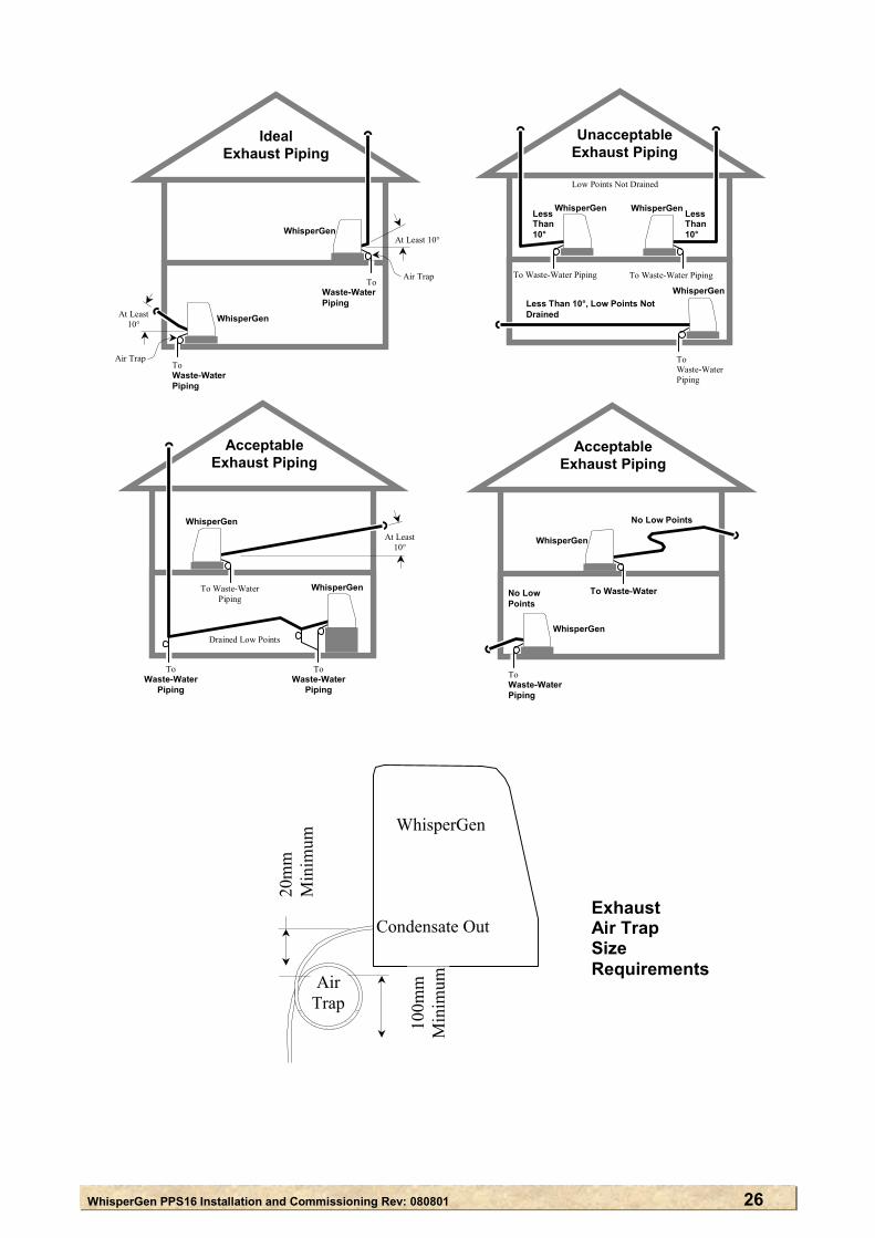
Condensate drains shall be run from all points in the exhaust where condensate is likely to be trapped. The condensate shall be drained into the waste water tank, or a suitable collection point for combustion condensate. Condensate drains shall contain an air trap to prevent exhaust gases leaking into the boat, or living spaces. The minimum air trap tube size is 10mm for vented drains/tanks and 15mm for non-vented tanks.
Warning: For marine installations the exhaust outlet shall not be submerged at any time. See Figure 10:
Exhaust piping for marine use. Warning: The exhaust pipe shall always have a slope of at least 10° relative to the horizon. Momentary
changes of slope, to less than 10°relative to the horizon (caused by a boat going over a wave or swell), are acceptable. See Figure 10: Exhaust piping for marine use.
Warning: The exhaust back-pressure, measured at the WhisperGen exhaust port shall not exceed 7mm
H₂0 with Exhaust Temp greater than 400°C when the Air % is at approximately 100%. This is about 20mm H₂0 with the Exhaust Temp less than 30°C. Higher back pressures will significantly reduce the power output of the WhisperGen.
Warning: The condensate drain shall be free from obstructions at all times.
The service connection on the back of the WhisperGen has an ISO Rp 1¼ female pipe thread.
The condensate drain uses 13mm inside diameter tubing. The drain, or pipe, shall not be higher than the service connection on the WhisperGen. The exhaust pipe shall be: ● short with few bends; and ● fitted with a weather protection cowling at the exhaust outlet.
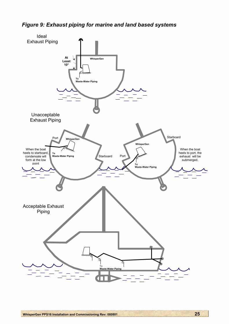
Extra exhaust pipe slope may need to be installed to compensate for boat heel. This is especially important for a yacht which has an exhaust pipe running from port to starboard.
WhisperGen PPS16 Installation and Commissioning Rev: 080801 24
To set up the exhaust system:
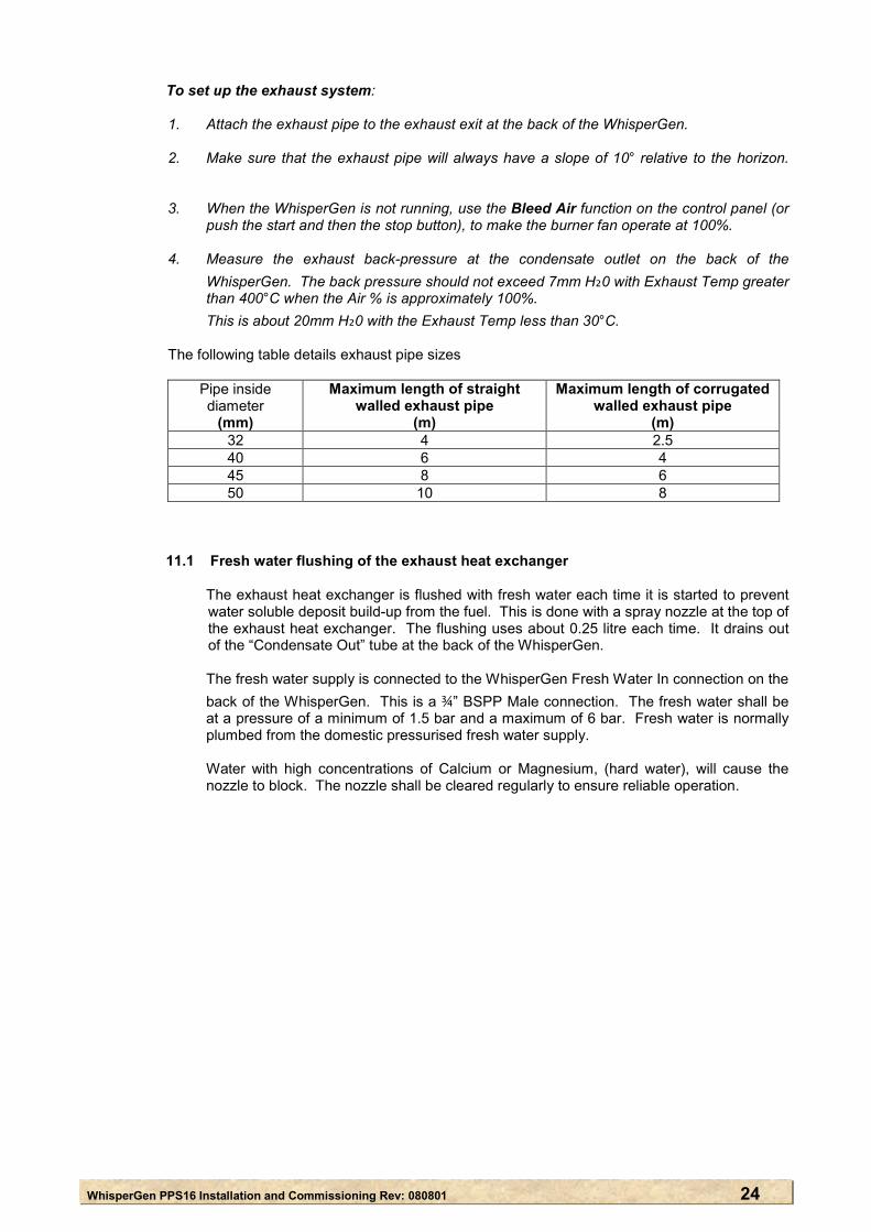
1. Attach the exhaust pipe to the exhaust exit at the back of the WhisperGen. 2. Make sure that the exhaust pipe will always have a slope of 10° relative to the horizon.
3. When the WhisperGen is not running, use the Bleed Air function on the control panel (or
push the start and then the stop button), to make the burner fan operate at 100%. 4. Measure the exhaust back-pressure at the condensate outlet on the back of the
WhisperGen. The back pressure should not exceed 7mm H₂0 with Exhaust Temp greater than 400°C when the Air % is approximately 100%. This is about 20mm H₂0 with the Exhaust Temp less than 30°C.
The following table details exhaust pipe sizes
Pipe inside diameter
(mm)
Maximum length of straight walled exhaust pipe
(m)
Maximum length of corrugated walled exhaust pipe
(m) 32 4 2.5 40 6 4 45 8 6 50 10 8
11.1 Fresh water flushing of the exhaust heat exchanger The exhaust heat exchanger is flushed with fresh water each time it is started to prevent
water soluble deposit build-up from the fuel. This is done with a spray nozzle at the top of the exhaust heat exchanger. The flushing uses about 0.25 litre each time. It drains out of the “Condensate Out” tube at the back of the WhisperGen.
The fresh water supply is connected to the WhisperGen Fresh Water In connection on the
back of the WhisperGen. This is a ¾” BSPP Male connection. The fresh water shall be at a pressure of a minimum of 1.5 bar and a maximum of 6 bar. Fresh water is normally plumbed from the domestic pressurised fresh water supply.
Water with high concentrations of Calcium or Magnesium, (hard water), will cause the
nozzle to block. The nozzle shall be cleared regularly to ensure reliable operation.
WhisperGen PPS16 Installation and Commissioning Rev: 080801
Figure 9: Exhaust piping for marine and land based systems
S
tShe
c
P
WhisperGen
WhisperGen
To Waste-Water Piping
Unacceptable Exhaust Piping
Le1
Ideal Exhaust Piping
WhisperGen
To Waste-Water Piping
To Waste-Water Piping
To Waste-Water PipingTo Waste-Water Piping
Acceptable Exhaust Piping
tarboard
When the boat heels to port, the
Por
exhaust will be tarboard submerged.When the boat els to starboard, ondensate will
form at the low point
ort
At ast 0°
25
WhisperGen PPS16 Installation and Commissioning Rev: 080801 26
Condensate Out
20m
m
Min
imum
WhisperGen
100m
m
Min
imum
Air Trap
ExhaustAir Trap Size Requirements
To Waste-Water Piping
WhisperGenLess Than10°
Less Than 10°, Low Points Not Drained
To Waste-Water Piping
WhisperGen
Unacceptable Exhaust Piping
Low Points Not Drained
WhisperGen Less Than 10°
To Waste-Water Piping
Acceptable Exhaust Piping
To Waste-Water
Piping
WhisperGen
Drained Low Points
To Waste-Water Piping
WhisperGen At Least
10°
To Waste-Water
Piping
Ideal Exhaust Piping
ToWaste-Water Piping
WhisperGen At Least 10°
To Waste-Water Piping
WhisperGen At Least 10°
Air Trap
Air Trap
Acceptable Exhaust Piping
To Waste-Water Piping
WhisperGen
No Low Points
To Waste-Water
WhisperGen
No Low Points
WhisperGen PPS16 Installation and Commissioning Rev: 080801 Commissioning checklist 1
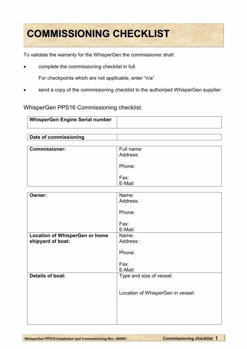
CCCOOOMMMMMMIIISSSSSSIIIOOONNNIIINNNGGG CCCHHHEEECCCKKKLLLIIISSSTTT To validate the warranty for the WhisperGen the commissioner shall: • complete the commissioning checklist in full.
For checkpoints which are not applicable, enter “n/a”
• send a copy of the commissioning checklist to the authorised WhisperGen supplier.
WhisperGen PPS16 Commissioning checklist.
WhisperGen Engine Serial number
Date of commissioning
Commissioner:
Full name: Address: Phone: Fax: E-Mail:
Owner: Name:
Address: Phone: Fax: E-Mail:
Location of WhisperGen or home shipyard of boat:
Name: Address: Phone: Fax: E-Mail:
Details of boat: Type and size of vessel: Location of WhisperGen in vessel:
WhisperGen PPS16 Installation and Commissioning Rev: 080801 Commissioning checklist 2
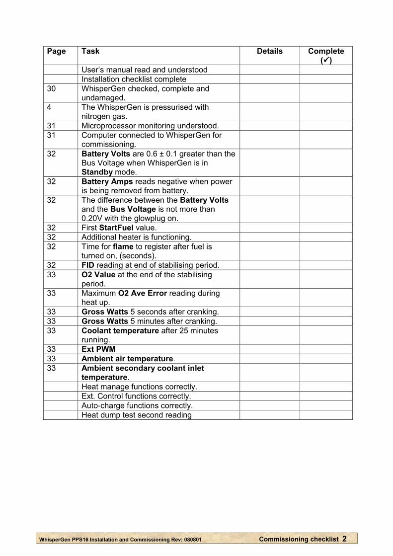
Page Task Details Complete
( ) User’s manual read and understood Installation checklist complete 30 WhisperGen checked, complete and
undamaged.
4 The WhisperGen is pressurised with nitrogen gas.
31 Microprocessor monitoring understood. 31 Computer connected to WhisperGen for
commissioning.
32 Battery Volts are 0.6 ± 0.1 greater than the Bus Voltage when WhisperGen is in Standby mode.
32 Battery Amps reads negative when power is being removed from battery.
32 The difference between the Battery Volts and the Bus Voltage is not more than 0.20V with the glowplug on.
32 First StartFuel value. 32 Additional heater is functioning. 32 Time for flame to register after fuel is
turned on, (seconds).
32 FID reading at end of stabilising period. 33 O2 Value at the end of the stabilising
period.
33 Maximum O2 Ave Error reading during heat up.
33 Gross Watts 5 seconds after cranking. 33 Gross Watts 5 minutes after cranking. 33 Coolant temperature after 25 minutes
running.
33 Ext PWM 33 Ambient air temperature. 33 Ambient secondary coolant inlet
temperature.
Heat manage functions correctly. Ext. Control functions correctly. Auto-charge functions correctly. Heat dump test second reading
WhisperGen PPS16 Installation and Commissioning Rev: 080801 Commissioning checklist 3
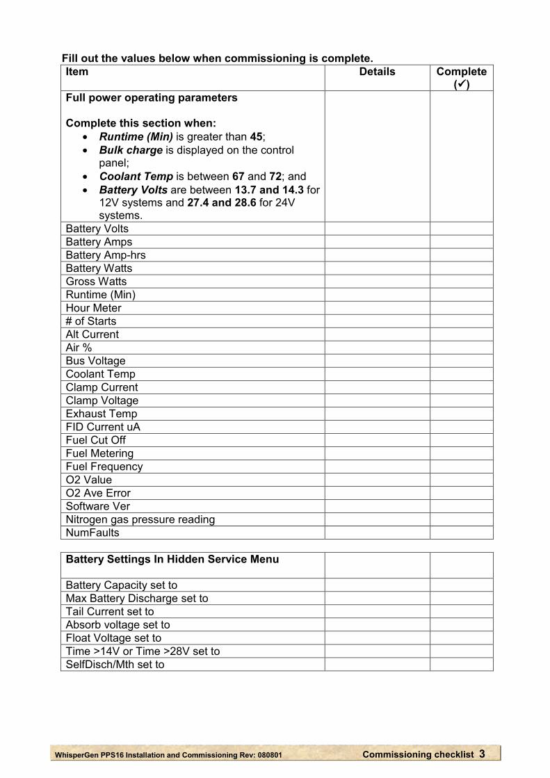
Fill out the values below when commissioning is complete. Item Details Complete
( ) Full power operating parameters Complete this section when:
• Runtime (Min) is greater than 45; • Bulk charge is displayed on the control
panel; • Coolant Temp is between 67 and 72; and • Battery Volts are between 13.7 and 14.3 for
12V systems and 27.4 and 28.6 for 24V systems.
Battery Volts Battery Amps Battery Amp-hrs Battery Watts Gross Watts Runtime (Min) Hour Meter # of Starts Alt Current Air % Bus Voltage Coolant Temp Clamp Current Clamp Voltage Exhaust Temp FID Current uA Fuel Cut Off Fuel Metering Fuel Frequency O2 Value O2 Ave Error Software Ver Nitrogen gas pressure reading NumFaults
Battery Settings In Hidden Service Menu
Battery Capacity set to Max Battery Discharge set to Tail Current set to Absorb voltage set to Float Voltage set to Time >14V or Time >28V set to SelfDisch/Mth set to
WhisperGen PPS16 Installation and Commissioning Rev: 080801 Commissioning checklist 4
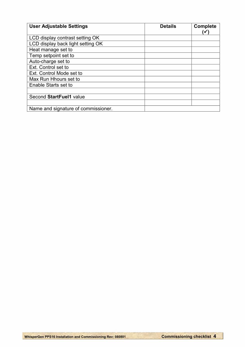
User Adjustable Settings Details Complete ( )
LCD display contrast setting OK LCD display back light setting OK Heat manage set to Temp setpoint set to Auto-charge set to Ext. Control set to Ext. Control Mode set to Max Run Hhours set to Enable Starts set to Second StartFuel1 value Name and signature of commissioner.
WhisperGen PPS16 Installation and Commissioning Rev: 080801 27
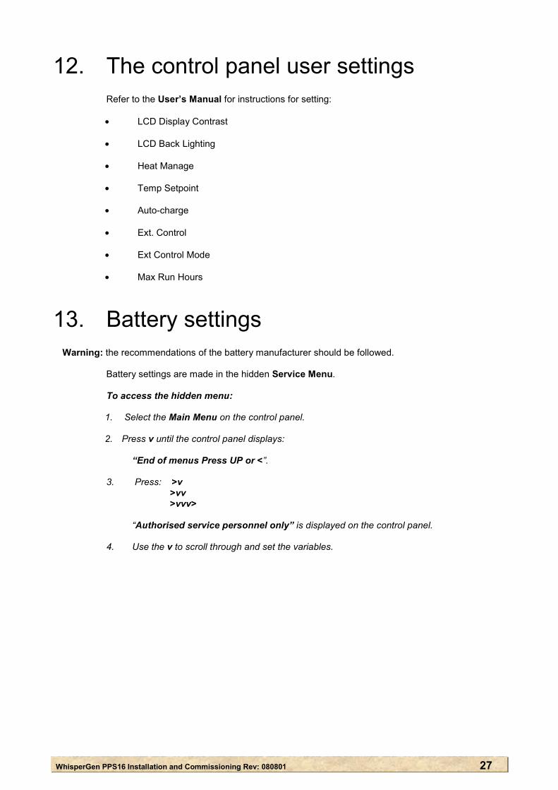
12. The control panel user settings Refer to the User’s Manual for instructions for setting:
• LCD Display Contrast • LCD Back Lighting
• Heat Manage
• Temp Setpoint
• Auto-charge
• Ext. Control
• Ext Control Mode
• Max Run Hours
13. Battery settings
Warning: the recommendations of the battery manufacturer should be followed. Battery settings are made in the hidden Service Menu.
To access the hidden menu:
1. Select the Main Menu on the control panel. 2. Press v until the control panel displays:
“End of menus Press UP or <”.
3. Press: >v >vv >vvv>
“Authorised service personnel only” is displayed on the control panel. 4. Use the v to scroll through and set the variables.
WhisperGen PPS16 Installation and Commissioning Rev: 080801 28
The battery settings are:
• Battery Capacity This is the battery capacity in ampere hours, at the 20 hour rate of the battery. • Max Battery Discharge This is the amount the battery can be discharged as a decimal percentage of the Battery
Capacity before the Auto-Charge function will automatically start the WhisperGen, charge the battery, and then stop the WhisperGen. The default setting of 0.35 (that is 35%), is usually adequate for most systems.
• Tail Current When the battery current reaches the Tail Current during charging, the battery is defined
by the WhisperGen as charged. The default setting for Tail current is 0.07 (7%), of the Ampere hour rating of the battery
and this is adequate for most systems. For example: for a 300 Ah battery, when the battery is at absorbtion voltage and the charging current drops to 21 amps, the battery is defined as charged, (300 x 0.07 = 21).
• Absorb Voltage Warning: The Absorb Voltage is specific to the battery. Battery manufacturer’s
recommendations shall be followed. The Absorb Voltage is the maximum voltage for the battery during battery charging. The
Absorb Voltage is specific to the battery. The default setting is 14.4V for 12V systems and 28.8V for 24V systems. This is usually
adequate for lead acid or gel batteries. • Float Voltage Warning: The Float Voltage is specific to the battery. Battery manufacturer’s
recommendations shall be followed. This is the voltage which the battery is held at if the WhisperGen continues running after
the battery has been defined by the WhisperGen as fully charged. The default setting is 13.8V for 12V systems and 27.6V for 24V systems. • Time >14V This is the maximum time, in hours, that the battery bank can be held above 14V for 12V
systems and 28V for 24V systems, before the battery is considered to be fully charged. It is a back-up to the Tail Current to prevent the battery being held at high voltage if the
load should exactly match the generation capability of the WhisperGen, or an old battery is being used.
The default setting is 4 hours. It shall be greater for larger batteries and less for smaller
batteries. • SelfDisch/Mth Warning: The SelfDisch/Mth is specific to the battery and the recommendations of the
battery manufacturer shall be followed. This is the self-discharge rate of the battery bank expressed as a decimal % per month
when no external load is applied. For example, 0.1 is equal to 10% self discharge per month. The default setting is 0.05. This is usually adequate for gel batteries. For lead acid batteries, the value should be increased to 0.10.
WhisperGen PPS16 Installation and Commissioning Manual Rev: 080801 29
14. WhisperGen check To check the WhisperGen before commissioning:
1. Remove the enclosure cover and ensure that:
• spare parts, tools and the User’s Manual are present; • there is no damage to the WhisperGen engine; • the burner is correctly positioned; and • the red silicon rubber burner seal, and springs are in place.
If the WhisperGen is damaged, or parts are missing, contact the WhisperGen distributor. 2. Ensure that the WhisperGen has been pressurised with nitrogen gas.
See page 4 Pressurising the WhisperGen, in the Installation section of this manual. 3. Ensure that the exhaust heat exchanger has been bolted to the burner. See page 5 in the Installation section of this manual.
15. Monitoring the WhisperGen using the Control Panel. Warning: If Auto restart is set to >0, the WhisperGen may attempt to restart automatically After a fault. See the WhisperGen User’s Manual for control panel operation. The WhisperGen control system monitors the starting, and running phase of the WhisperGen by checking the values given by the sensors. If the microprocessor finds that sensor values are outside a specific range, (set in the WhisperGen control program), then the WhisperGen produces a warning or fault, and in some cases it is shut down. To restart the WhisperGen after it has automatically shut down: • If the cause of the shutdown is known, fix the fault, and clear the fault from the screen.
Fault odes and suggested fixes are given in the WhisperGen User’s Manual. • try to restart the WhisperGen. The WhisperGen must complete its cooldown routine
before a restart.
WhisperGen PPS16 Installation and Commissioning Manual Rev: 080801 30
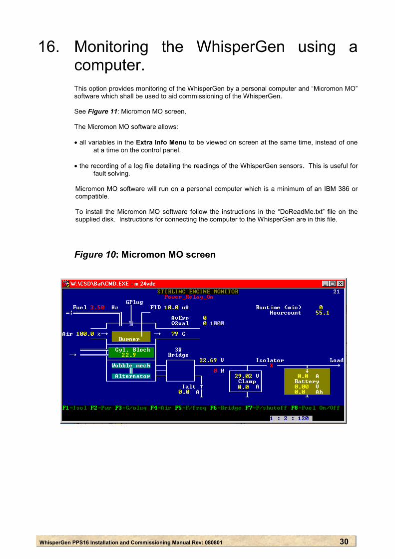
16. Monitoring the WhisperGen using a computer. This option provides monitoring of the WhisperGen by a personal computer and “Micromon MO” software which shall be used to aid commissioning of the WhisperGen. See Figure 11: Micromon MO screen. The Micromon MO software allows: • all variables in the Extra Info Menu to be viewed on screen at the same time, instead of one
at a time on the control panel. • the recording of a log file detailing the readings of the WhisperGen sensors. This is useful for
fault solving. Micromon MO software will run on a personal computer which is a minimum of an IBM 386 or compatible. To install the Micromon MO software follow the instructions in the “DoReadMe.txt” file on the supplied disk. Instructions for connecting the computer to the WhisperGen are in this file.
Figure 10: Micromon MO screen
WhisperGen PPS16 Installation and Commissioning Manual Rev: 080801 31
17. Running the WhisperGen for the first time
To run the WhisperGen for the first time: 1. Complete sections 1 to 15 of this manual. 2. Connect the monitoring computer to the WhisperGen and start
Micromon MO.
3. Put the WhisperGen into Standby mode by pressing the start button for five seconds.
4. Check that the Battery Volts are 0.6 ± 0.2 greater than the Bus Voltage. If not, check that the battery voltage sense wires are connected.
5. Ensure that the WhisperGen is the only charging device connected to the battery and that there is no current going into, or out of the battery.
6. Push the WhisperGen start button for one second.
7. On the Micromon MO screen check that Battery Amps shows a negative reading. If the Battery Amps reading is positive, reverse the battery current shunt sense wires at either the current shunt, or at terminals 7 and 8.
8. The WhisperGen will power up and turn on the glow plug. This takes about 15 seconds. Check that Battery Volts is a maximum of 0.20 volts greater than the Bus voltage.
With the glow plug on, the load on a 12 volt battery should be approximately 35 amps. The load on a 24V battery should be approximately 18 amps.
9. Press the stop button for one second. The WhisperGen will shut down. 10. Select the Installation Menu on the control panel and select the following settings:
• Enable Starts shall be set to 2; • Heat Manage shall be set to Off. • Auto-charge shall be set to Off. • Ext. Control shall be set to Off. • Max Run Hours shall be set to 25.
11. Write down the StartFuel1 value. This is about variable 73 on the Micromon MO screen. 12. Press the start button
The additional heater water pump should run every time the WhisperGen is powered up, even if it is not producing heat.
13. If an additional water heater is fitted, turned on at the main switch, controlled by the
WhisperGen, and the Coolant Temp is less than the Temp Setpoint, check that the additional water heater coolant pump is working correctly.
14. Record the time it takes between the fuel pump being turned on and a flame being
registered by the WhisperGen on the control panel. This shall be approximately one minute. When a flame is present the control panel will display “Flame present”.
WhisperGen PPS16 Installation and Commissioning Manual Rev: 080801 32
15. Write down the O2 start value which is about variable number 70 on the Micromon MO
variables screen. The WhisperGen goes into a stabilising period next, while the burner stabilises. This will
last for about a minute. 16. At the end of the stabilising stage check that:
• the FID Current is greater than 0.5uA; and • the O2 Value is within 200 of the O2 start value.
(Refer to the User Manual for further information.) The WhisperGen goes into a Heating Up stage next.
17. Check that the O2 Ave Error is less than 100. The WhisperGen engine will be cranked when the exhaust temperature reaches between
150°C and 200°C. 18. Check that the Gross Watts rises to:
• a minimum of 200W five seconds after cranking; and • a minimum of 500W five minutes after cranking.
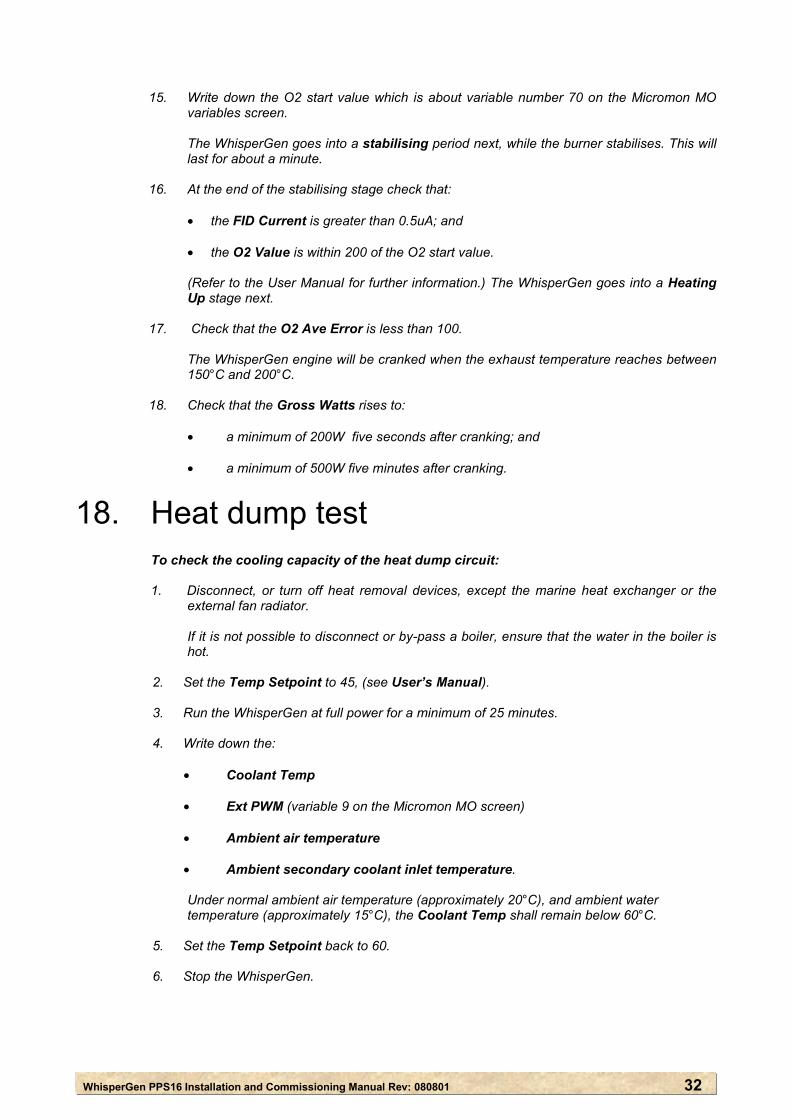
18. Heat dump test To check the cooling capacity of the heat dump circuit:
1. Disconnect, or turn off heat removal devices, except the marine heat exchanger or the external fan radiator.
If it is not possible to disconnect or by-pass a boiler, ensure that the water in the boiler is
hot.
2. Set the Temp Setpoint to 45, (see User’s Manual).
3. Run the WhisperGen at full power for a minimum of 25 minutes. 4. Write down the:
• Coolant Temp • Ext PWM (variable 9 on the Micromon MO screen) • Ambient air temperature • Ambient secondary coolant inlet temperature.
Under normal ambient air temperature (approximately 20°C), and ambient water temperature (approximately 15°C), the Coolant Temp shall remain below 60°C.
5. Set the Temp Setpoint back to 60. 6. Stop the WhisperGen.
WhisperGen PPS16 Installation and Commissioning Manual Rev: 080801 33
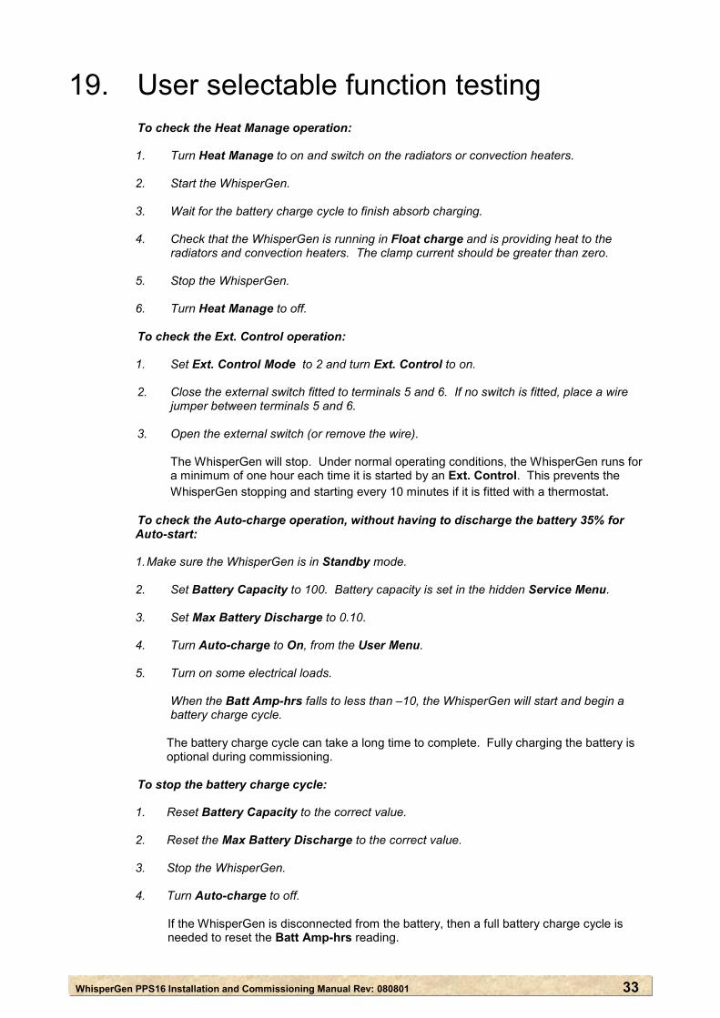
19. User selectable function testing To check the Heat Manage operation:
1. Turn Heat Manage to on and switch on the radiators or convection heaters. 2. Start the WhisperGen. 3. Wait for the battery charge cycle to finish absorb charging. 4. Check that the WhisperGen is running in Float charge and is providing heat to the
radiators and convection heaters. The clamp current should be greater than zero.
5. Stop the WhisperGen. 6. Turn Heat Manage to off. To check the Ext. Control operation: 1. Set Ext. Control Mode to 2 and turn Ext. Control to on. 2. Close the external switch fitted to terminals 5 and 6. If no switch is fitted, place a wire
jumper between terminals 5 and 6. 3. Open the external switch (or remove the wire). The WhisperGen will stop. Under normal operating conditions, the WhisperGen runs for
a minimum of one hour each time it is started by an Ext. Control. This prevents the WhisperGen stopping and starting every 10 minutes if it is fitted with a thermostat.
To check the Auto-charge operation, without having to discharge the battery 35% for Auto-start: 1. Make sure the WhisperGen is in Standby mode. 2. Set Battery Capacity to 100. Battery capacity is set in the hidden Service Menu. 3. Set Max Battery Discharge to 0.10. 4. Turn Auto-charge to On, from the User Menu. 5. Turn on some electrical loads. When the Batt Amp-hrs falls to less than –10, the WhisperGen will start and begin a
battery charge cycle. The battery charge cycle can take a long time to complete. Fully charging the battery is
optional during commissioning. To stop the battery charge cycle: 1. Reset Battery Capacity to the correct value. 2. Reset the Max Battery Discharge to the correct value. 3. Stop the WhisperGen. 4. Turn Auto-charge to off. If the WhisperGen is disconnected from the battery, then a full battery charge cycle is
needed to reset the Batt Amp-hrs reading.
WhisperGen PPS16 Installation and Commissioning Manual Rev: 080801 34
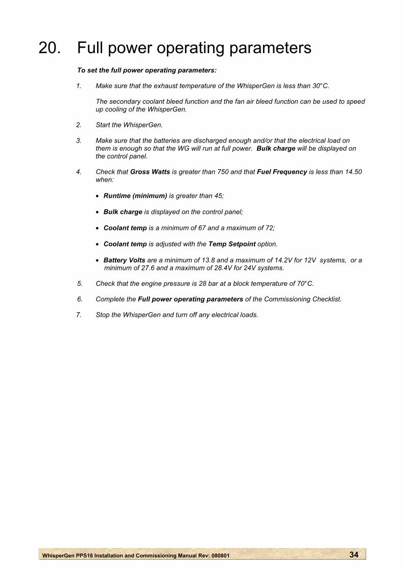
20. Full power operating parameters To set the full power operating parameters:
1. Make sure that the exhaust temperature of the WhisperGen is less than 30°C. The secondary coolant bleed function and the fan air bleed function can be used to speed
up cooling of the WhisperGen. 2. Start the WhisperGen. 3. Make sure that the batteries are discharged enough and/or that the electrical load on
them is enough so that the WG will run at full power. Bulk charge will be displayed on the control panel.
4. Check that Gross Watts is greater than 750 and that Fuel Frequency is less than 14.50
when: • Runtime (minimum) is greater than 45; • Bulk charge is displayed on the control panel; • Coolant temp is a minimum of 67 and a maximum of 72; • Coolant temp is adjusted with the Temp Setpoint option. • Battery Volts are a minimum of 13.8 and a maximum of 14.2V for 12V systems, or a
minimum of 27.6 and a maximum of 28.4V for 24V systems. 5. Check that the engine pressure is 28 bar at a block temperature of 70°C.
6. Complete the Full power operating parameters of the Commissioning Checklist.
7. Stop the WhisperGen and turn off any electrical loads.
WhisperGen PPS16 Installation and Commissioning Manual Rev: 080801 35
21. Completing commissioning and filling out the commissioning checklist.
To complete the commissioning procedure:
1. Start the WhisperGen and record the second StartFuel1 value at the end of the
commissioning checklist. There will be a slight difference between the two values. 2. Complete the Commissioning Details section at the back of the User’s Manual. 3. Complete the Commissioning Checklist in the Installation and Commissioning manual
and return it to the Whisper Tech Limited and the distributor.
WhisperGen PPS16 Installation and Commissioning Manual Rev: 080801 36
APPENDIX A: Recommended components for the coolant circuits
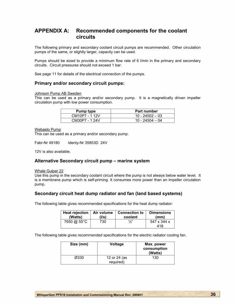
The following primary and secondary coolant circuit pumps are recommended. Other circulation pumps of the same, or slightly larger, capacity can be used. Pumps should be sized to provide a minimum flow rate of 6 l/min in the primary and secondary circuits. Circuit pressures should not exceed 1 bar. See page 11 for details of the electrical connection of the pumps. Primary and/or secondary circuit pumps: Johnson Pump AB Sweden This can be used as a primary and/or secondary pump. It is a magnetically driven impeller circulation pump with low power consumption.
Pump type Part number
CM10P7 - 1 12V 10 - 24502 – 03 CM30P7 - 1 24V 10 - 24504 – 04
Webasto Pump This can be used as a primary and/or secondary pump. Fabr-Nr 49180 Identy-Nr 35853D 24V 12V is also available. Alternative Secondary circuit pump – marine system Whale Gulper 22 Use this pump in the secondary coolant circuit where the pump is not always below water level. It is a membrane pump which is self-priming. It consumes more power than an impeller circulation pump.
Secondary circuit heat dump radiator and fan (land based systems) The following table gives recommended specifications for the heat dump radiator:
Heat rejection
(Watts) Air volume
(l/s) Connection to
coolant Dimensions
(mm) 7650 @ 55°C 730 ½” 547 x 344 x
418
The following table gives recommended specifications for the electric radiator cooling fan.
Size (mm) Voltage Max. power consumption
(Watts) Ø330 12 or 24 (as
required) 130
WhisperGen PPS16 Installation and Commissioning Manual Rev: 080801 37
Coolant The primary circuit coolant must contain a corrosion inhibitor because the engine is largely manufactured from aluminium alloy. If ethylene glycol is used as the corrosion inhibitor, a minimum of 35% undiluted glycol to 65% fresh water solution shall be used. It is essential that the primary coolant is clean and free fro debris. Foreign particles can obstruct internal coolant passages and damage the WhisperGen. Contaminated circuits should be fitted with sludge traps, upstream of the WhisperGen. Potable water only should be used in the primary circuit to cool the WhisperGen. A corrosion inhibitor must be added. APPENDIX B: Battery specification
A deep-cycle lead acid or gel battery with a minimum capacity of 200 ampere hours at 12V or 24V shall be used. The battery cable size shall be a minimum of 35mm². The maximum run length for the battery cable shall be: ● 4 metres for a 12V system; and ● 8 metres for a 24V system. If longer battery cables are required they shall be proportionally larger in size. For example, for 8 metre cables for a 12 volt system, the cable size shall be a minimum of 70mm².
WhisperGen PPS16 Installation and Commissioning Manual Rev: 080801 38
APPENDIX C: Recommendation for circuit breaker The recommended circuit breaker is Blue Seas type 7103 (125A), 30V or similar. A 200 amp fuse can be used with an isolating switch.