white paper blu-ray disc™ format · the recordable layer(s) for a recordable blu-ray disc™...
TRANSCRIPT

© Blu-ray Disc Association 2012. All rights reserved.
White Paper
Blu-ray Disc™ Format
1. B Physical Format Specifications for BD-R
6th Edition
December, 2012

White Paper Blu-ray Disc™ Format BD-R
Condition of Publication
2 © Blu-ray Disc Association 2012. All rights reserved.
COPYRIGHT All rights reserved. This document contains information that is proprietary information of the Blu-ray Disc Association and its members and may not be used, copied or distributed without the written permission of the Blu-ray Disc Association or its License Office. All other use, copying and distribution are prohibited. TRADEMARK Blu-ray Disc™, Blu-ray™, Blu-ray 3D™, BD-Live™, BONUSVIEW™, BDXL™, AVCREC™, and the logos are trademarks of the Blu-ray Disc Association. DISCLAIMER The information contained herein is believed to be accurate as of the date of publication. However, none of the Blu-ray Disc Association, its Members, or its License Office will be liable for any damages, including indirect or consequential, from use of the White Paper or reliance on the accuracy of this document. LICENSING License is required from the Blu-ray Disc Association for the application of the System Description Blu-ray Disc™ Format in both disc and equipment products. NOTICE For any further explanation of the contents of this document, or in case of any perceived inconsistency or ambiguity of interpretation, please consult with: Blu-ray Disc Association
License Office 10 Universal City Plaza, T-100, Universal City, CA 91608 U.S.A. Fax.: +1-818-763-9027 Web Site: http://www.blu-raydisc.info E-mail: [email protected]

White Paper Blu-ray Disc™ Format BD-R
INDEX
© Blu-ray Disc Association 2012. All rights reserved. 3
INDEX
1. Main Parameters of Recordable Blu-ray Disc™
2. Recording and playback technology 2.1 Track format 2.2 Recording and playback principles 2.3 Write strategy
2.3.1 N-1 write strategy 2.3.2 N/2 write strategy 2.3.3 Castle write strategy
2.4 Tilt Margin 2.5 Limit Equalizer 2.6 Measurement Results
3. BDXL™ technologies 3.1 Main parameters 3.2 Disc Structure 3.3 Write strategy and Extended Adaptive Mark Compensation 3.4 i-MLSE technology
4. Modulation Code and Error-Correction Code
4.1 Modulation Code 4.2 Error-Correction Code
5. Address format using Groove Wobbles 6. Disc Management
6.1 Defect Management and Logical Overwrite 6.2 Recording Management

White Paper Blu-ray Disc™ Format BD-R
1. Main parameter of Recordable Blu-ray Disc™
4 © Blu-ray Disc Association 2012. All rights reserved.
1. Main parameter of Recordable Blu-ray Disc™
Table 1.1 shows the main parameters of Blu-ray Disc™ Recordable (BD-R). To maximize capacity and performance, the main optical system parameters of the Blu-ray™ Recordable Disc include a laser diode with a wavelength 405 nm and an objective lens with a NA of 0.85. Additionally, the current maximum User-Data transfer-rate is 216 Mbps (6x) for SL (Single Layer) & DL (Dual Layer), and 144 Mbps (4x) for TL (Triple Layer) & QL (Quadruple Layer) which will be explained in Chapter 4. The Channel modulation is 17PP (Parity Preserving) and the recording area can be either On-Groove or In-Groove. Table 1.1:Main parameters for SL & DL
Recordable Blu-ray Disc™
Diameter 120 mm 80 mm
Capacity (SL) 25 GB, 27 GB (DL) 50 GB, 54 GB
(SL) 7.8 GB (DL) 15.6 GB
Wavelength (λ) of laser diode
405 nm
Recording Power (SL) : ≤ 6 mW (1x), ≤ 7 mW (2x), ≤ 10.5 mW (4x), ≤ 14 mW (6x) (DL) : ≤ 12 mW (1x), ≤ 14 mW (2x), < 18 mW (4x), < 22 mW (6x)
NA of objective lens 0.85 Cover Layer thickness 0.10 mm (Layer L0,SL), 0.075 mm (Layer L1)
Recording Area On-Groove / In-Groove Address method MSK (Minimum-Shift Keying) & STW (Saw-Tooth Wobble)
Rotation CLV (Constant Linear Velocity) Track Pitch 0.32 μm
Channel modulation 17PP
Minimum Mark length 0.149 μm for 25 GB, 50 GB0.138 μm for 27 GB, 54 GB
0.149 μm
Total efficiency 81.70 % User-Data transfer-rate 36 Mbps ~ 216 Mbps
Fig. 1.1 specifies the outline of the Groove geometries for On-Groove and In-Groove. The Groove is defined as the portion of the disc that is recorded by the Laser-Beam Recorder.
Fig. 1.1 Outline of Groove geometry

White Paper Blu-ray Disc™ Format BD-R
2. Recording and playback technologies
© Blu-ray Disc Association 2012. All rights reserved. 5
2. Recording and playback technologies 2.1 Track format The Track format of Recordable Blu-ray Disc™ is Groove-recording, i.e., recording data only On-Groove or In-Groove Tracks. For the Groove recording method, Lands are sandwiched between adjacent Grooves to block heat transfer between the Grooves during recording, preventing signal quality deterioration in one Groove Track due to the influence of recording data in an adjacent Groove Tracks with a narrow Track Pitch. The Track Pitch between Grooves in Recordable Blu-ray Disc™ is 0.32 μm. 2.2 Recording and playback principles
The Recordable Layer(s) for a Recordable Blu-ray Disc™ employ either organic or inorganic materials. For a Single-Layer Recordable Blu-ray Disc™, the thickness from the disc surface to the Recording Layer is 100 μm. For a Dual-Layer Recordable Blu-ray Disc™, the thickness from the disc surface to the Front Layer (Layer L1) is 75 μm, and to the Rear Layer (Layer L0) is 100 μm. For the Dual-Layer disc, the laser beam must be transmitted through the Front Layer for data recording/playback on the Rear Layer. While Recording Layer L0, the laser beam is severely out of focus for Layer L1 resulting in a very low optical density which prevents affecting the recording characteristics of Layer L1. Therefore, the Front Layer is required to provide an optical transmittance of 50% or more, regardless of its recorded state (whether data-recorded or blank).
The Recordable Blu-ray Disc™ specification allows for multiple variations in the recording capacity, to
allow user’s selection according to the disc purchased. According to the Specifications Book, the 120 mm Single-Layer type has two different discs with capacities of 25 and 27 GB, while the Dual-Layer type has capacities of 50 and 54 GB. The two different capacities of each type have been realized by using different linear recording densities, but all using the same Track Pitch. The minimum length (2T) of Marks recordable on a disc is 0.149 and 0.139 μm, in the order of the recording capacity. Additionally, the Recordable Blu-ray Disc™ specification allows for 80 mm discs using a single linear recording density. This results in capacities of 7.8 GB for Single-Layer and 15.6 GB for Dual-Layer 80 mm discs.
The basic recording/playback system for the Recordable Blu-ray Disc™ is shown in Fig. 2.2.1. The User Data, already properly formatted (ECC (Error-Correction Code) and other Sector Information added), is modulated or encoded into a 17PP (one seven Parity preserve/Prohibit RMTR) NRZI (Non-Return to Zero Invert) signal. This 17PP NRZI is sent to a write pulse compensator where the signal is modulated into a multi-pulse signal (see Fig. 2.3.1.1). By adjusting the leading edge of the first pulse and the trailing edge of the cooling pulse of the multi-pulse signal, we can control the amount of thermal accumulation relative to the Mark length, enabling the accurate placement of Mark edges. The pulse waveform thus modulated is sent to a laser driver circuit, which modulates the power of laser beam to record Mark/Space data on a Recordable Blu-ray Disc™. To play-back recorded data, the reproduced signal is fed through an Equalizer to the Phase Lock Loop (PLL). The output signal of the Equalizer is also fed to the Analog to Digital converter (A/D) to be converted to a digital signal using the PLL clock timing. The output of the A/D is then passed through a PRML (Partial-Response-Maximum-Likelihood) Channel to correct any initial bit errors, and output as a NRZI signal to demodulated from the 17PP code and any remaining errors corrected using the ECC (for more information see clause 4).

White Paper Blu-ray Disc™ Format BD-R
2. Recording and playback technologies
6 © Blu-ray Disc Association 2012. All rights reserved.
2
Fig. 2.2.1: Block diagram of BD drive
Optical Pick-up
Equalizer
Laser Driver
PLL
A/D
NA=0.85 / =406 nm
dataPRML
Write PulseCompensator
17PP BinaryData Modulator
Recordable Blu-ray DiscTM
recording
reproducing
This figure shows a block diagram of Recordable Blu-ray DiscTM drive.The 17PP modulated binary data is sent to the Write Pulse Compensator to control the mark edge position precisely. The output signal of Write Pulse Compensator goes through Laser Driver and Optical Pick-up. The Optical Pick-up has a spherical aberration compensator to focus on the both layers of the Dual-Layer disc.The reproduced signal was equalized and filtered and passed through PRML decoder to correct the in itial b it error.
Fig. 2.2.1 Basic recording/playback system of BD-R
As previously stated, the Recording Layer where the actual Marks and Spaces are formed employs either organic or inorganic materials. Fig. 2.2.2 shows the typical disc structures of Recordable Blu-ray Discs™. For example, Fuji Photo Film Co., Ltd. has successfully demonstrated BD-R that can be readily put into commercial production using organic materials. Furthermore, TDK has realized BD-R discs using inorganic materials (a Cu alloy layer and a Si layer). In addition to the type of inorganic materials used by TDK, it is also possible to use write-once phase change materials.
The mechanism of forming Marks on TDK’s media is described as follows. As the Recordable
Blu-ray Disc™ is irradiated with a train of modulated optical pulses of 2T, 3T and 4T as shown in Fig. 2.2.3, the recording Marks corresponding to their respective code lengths are formed on the disc. A part of the film (recorded Marks) where the laser beam is irradiated with higher power pulses will be heated and the two different films of Cu alloy and Si are mixed forming a CuSi -Alloy with lower reflectivity (Fig 2.2.4). The spaces between the Marks remain in their original state since the irradiation between the Marks is at a lower power.
This general method of using higher power irradiation to form Marks and lower power for Spaces is
consistent across both organic and inorganic materials; however the write pulse waveform will differ in each case. For the recorded optical disc of either organic or inorganic material, the Optical Pick-up using a focused laser beam reads differences in the physical characteristics (reflectivity) between the thus formed Marks and Spaces, thereby producing binary data in accordance with the reflectivity level.
Cover Layer Cover Layer
Protective Layer
Protective Layer
Reflective Layer
Reflective Layer
Substrate
Hard coat Hard coat
Substrate
Recording Layer(Dye)
Bonding Layer
Recording Layer(Si/Cu Alloy)
Inorganic type Organic type
Fig. 2.2.2 Disc structure

White Paper Blu-ray Disc™ Format BD-R
2. Recording and playback technologies
© Blu-ray Disc Association 2012. All rights reserved. 7
Fig. 2.2.3 Write Pulse Waveform
Fig. 2.2.4 TEM image of Recorded Mark on TDK’s BD-R disc
Regarding the organic materials, the recording and playback mechanism is similar to Dye-based DVD-R media. As is shown in Fig. 2.2.5, excellent recording Pit formation was obtained even at recording densities approximately five times greater than those of DVD-R media (equivalent to 25 GB capacity on a 12 cm-diameter disc). Some measurement results of recording/playback signal quality will be shown in 2.6.
Minimum-Mark length 0.149 µm, 0.138 µm
Mark

White Paper Blu-ray Disc™ Format BD-R
2. Recording and playback technologies
8 © Blu-ray Disc Association 2012. All rights reserved.
Fig. 2.2.5 SEM Photos of Recording Pits on Organic Dye-Based Optical Discs
Track Direction
In-Groove Recording On-Groove Recording

White Paper Blu-ray Disc™ Format BD-R
2. Recording and playback technologies
© Blu-ray Disc Association 2012. All rights reserved. 9
2.3 Write strategy
Three types of write strategies are defined in the Blu-ray Disc™ Recordable format; N-1 write strategy which requires one additional write pulse for each Channel-clock cycle beginning with a single pulse for a 2T Mark is applied for discs. N/2 write strategy which requires one additional write pulse for each 2 consecutive Channel-clock cycles is applied for discs. N/2 write strategy has a single write pulse for a 2T or 3T Mark, 2 write pulses for a 4T and 5T Mark, and so on. Castle write strategy which requires continued pulse with several power levels for each Mark is applied for discs.
In accordance with the characteristics of each Recording Layer of a disc, a disc manufacturer determines the write strategy parameters and embeds them in the HF modulated Groove Area and the Wobbled Groove Address of the disc.
2.3.1 N-1 write strategy
Fig. 2.3.1.1 schematically shows the N-1 write strategy for Blu-ray Disc™ Recordable format, which comprises pulse-modulated recording waveforms with four power levels of PW, PBW, PC and PS. Ttop denotes the duration of the first write pulses, dTtop the start time offset of the first write pulse from its reference position, TMP the duration of all following write pulses except the last pulse, TLP the duration of the last pulse and dTS the start time offset of the Space level from its reference position. Fig.2.3.1.1 shows an example of the write pulse waveform of a 4T Mark. The write pulse offsets (dTtop and dTS), the write pulse duration (Ttop, TMP and TLP) and the power levels (PW, PBW, PC and PS) are shown. To control Mark edge positions precisely, each parameter (dTtop, Ttop, TMP, TLP or dTS) is defined in 1/16 of the Channel-clock resolution.
PW
PS
NRZI 4TTw
dTtop
Ttop TMP
dTSPBW
TLP
PC
Fig. 2.3.1.1 N-1 write strategy
2.3.2 N/2 write strategy Fig. 2.3.2.1 schematically shows N/2 write strategy which comprises pulse-modulated recording
waveforms with four power levels of PW, PBW, PC and PS. Ttop denotes the duration of the first pulse, dTtop the start time offset of the first pulse from its reference position, TMP the duration of all following write pulses except the last pulse, TLP the duration of the last pulse, and dTS the start time offset of Space level from its reference position. Fig.2.3.2.1 shows an example of the write pulse waveform of 6T Mark. N/2 write strategy has one-half write pulse of Mark length. The write pulse offsets (dTtop and dTS), the write pulse duration (Ttop, TMP and TLP) and the power levels (PW, PBW, PC and PS) are shown. To control Mark edge positions precisely, each parameter (dTtop, Ttop, TMP, TLP or dTS) is defined in 1/16 of the system clock resolution.

White Paper Blu-ray Disc™ Format BD-R
2. Recording and playback technologies
10 © Blu-ray Disc Association 2012. All rights reserved.
Fig. 2.3.2.1 N/2 write strategy
2.3.3 Castle write strategy
Fig. 2.3.3.1 schematically shows the Castle write strategy which comprises pulse-modulated recording waveforms with four power levels of PW, PM, PC and PS. Ttop denotes the duration of the first pulse, dTtop the start time offset of the first pulse from its reference position, dTC the start time offset of the cooling pulse except the 2T write pulse, TLP the duration of the last pulse, and dTS the start time offset of the Space level from its reference position. Fig. 2.3.3.1 shows an example of the write pulse waveform of 6T Mark. The write pulse offsets (dTtop, dTC and dTS), the write pulse duration (Ttop and TLP), and the power levels (PW, PM, PC and PS) are shown. To control Mark edge positions precisely, each parameter (dTtop, Ttop, dTC, TLP or dTS) is defined by 1/16 of the Channel-clock resolution.
PMPS
6T
dTtop
PW
NRZI
Tw
Ttop
dTS PC
TLP
dTC
Fig. 2.3.3.1 Castle write strategy
6T
PW
PS
NRZI
Tw
dTtop
Ttop
dTS PBW
TMP
PC
TLP
6T
PW
PS
NRZI
Tw
dTtop
Ttop
dTS PBW
TMP
PC
TLP

White Paper Blu-ray Disc™ Format BD-R
2. Recording and playback technologies
© Blu-ray Disc Association 2012. All rights reserved. 11
2.4 Tilt Margin Fig. 2.4.1 shows the tangential and radial tilt margin characteristics of a Dual-Layer Recordable Blu-ray Disc™ on which data is recorded using adaptive Mark compensation and read out using PRML technology. The recording capacity is 50 GB. Both layers provide satisfactory bit error rate (bER) and tangential and radial tilt margins. The tilt margin of the Front Layer (Layer L1) is wider than that of Rear Layer (Layer L0), due to the thinner Front Layer Substrate and therefore less influence of tilt.
7
1.E-06
1.E-05
1.E-04
1.E-03
1.E-02
-1.2 -0.8 -0.4 0.0 0.4 0.8 1.2
Tangential Tilt [degree]
BE
R
1.E-06
1.E-05
1.E-04
1.E-03
1.E-02
-1.2 -0.8 -0.4 0.0 0.4 0.8 1.2
Radial Tilt [degree]
BE
R
Fig. 2.4.1: Dependences of bER on tilt angle
Layer L0
Layer L1
Layer L0
Layer L1
• This figure shows the dependences of bER on tilt angle for 50GB capacity.• Right side shows the radial tilt margin characteristics and left side shows the tangential tilt margin
characteristics.• At every graph, green bots are the results on Layer L0 and blue bots are results on Layer L1.• With PRML wide tilt margin was obtained in all conditions.• Radial tilt margins reached 0.7 degrees and tangential tilt margins attained 0.6 degrees.• Tilt margins on Layer L1 are wider than those on Layer L0 in both directions.• This results shows an influence of coma-aberration on Layer1 is smaller than that on Layer L0, because the
Cover Layer for Layer L1 is thinner than that for Layer L0.
Fig. 2.4.1 Tilt margins

White Paper Blu-ray Disc™ Format BD-R
2. Recording and playback technologies
12 © Blu-ray Disc Association 2012. All rights reserved.
Pre-Linear Equalizer
A/D
D D D
3D +
+
Limiter
In Out
Interpolate 1.5D
-k -k k k
SNR
SNR
Total noise level
Tmin.signal Tmin.signal Freq. Freq.
Disc noise
Disc noise
Boost around Tmin frequency
2.5 Limit Equalizer
Generally, the system for reading a playback signal uses a Linear Equalizer to improve the Signal-to-Noise Ratio (SNR) around minimum-length Marks and to suppress Inter-Symbol Interference. Disc noise exists mainly in a low-frequency region as shown in Fig. 2.5.1. When high frequencies around minimum-length Marks are selectively boosted using a Linear Equalizer, the minimum-Mark-length signal level can be markedly enhanced with only a little increase in the total amount of noise. That is, it is possible to improve the SNR by using a Linear Equalizer that boosts high frequency. However, since an excessive boosting of high frequencies causes an increase in Inter-Symbol Interference, a Conventional Linear Equalizer has a limitation to the improvement of the SNR.
Fig. 2.5.1 SNR improvement of Limit Equalizer
A Limit Equalizer is capable of boosting high frequencies without increasing Inter-Symbol Interference.
Fig. 2.5.2 shows the configuration of the Limit-Equalizer system for use in 17PP modulation. In this system, a Pre-Equalizer initially minimizes the Inter-Symbol Interference through the use of a Conventional Linear Equalizer as the Pre-Equalizer. The Limit Equalizer is located after the Pre-Equalizer.
Fig. 2.5.2 Configuration of Limit Equalizer
The Limit Equalizer has a similar construction as a Finite-Impulse-Response (FIR) Linear Equalizer,
except that the Limiter restricts the amplitude of part of playback signal. The FIR filter acts as a high-frequency-boosting Equalizer, and its gain is determined by coefficient “k.” The gain of a FIR filter
White Paper Blu-ray Disc™ Format BD-R
2. Recording and playback technologies
© Blu-ray Disc Association 2012. All rights reserved. 13
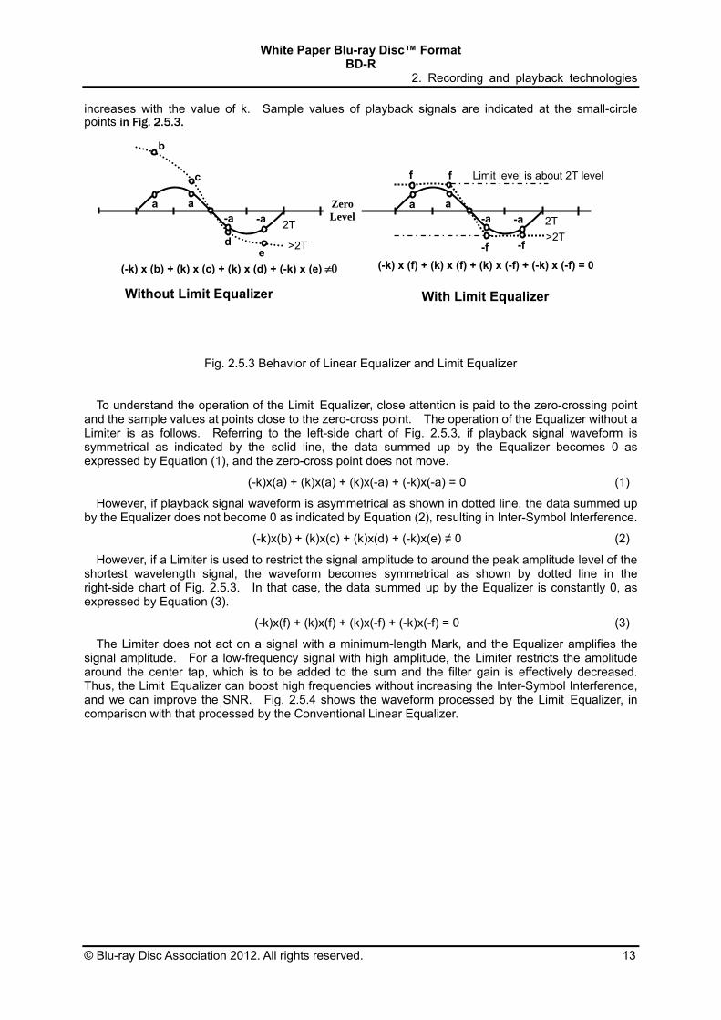
increases with the value of k. Sample values of playback signals are indicated at the small-circle points in Fig. 2.5.3.
Fig. 2.5.3 Behavior of Linear Equalizer and Limit Equalizer
To understand the operation of the Limit Equalizer, close attention is paid to the zero-crossing point
and the sample values at points close to the zero-cross point. The operation of the Equalizer without a Limiter is as follows. Referring to the left-side chart of Fig. 2.5.3, if playback signal waveform is symmetrical as indicated by the solid line, the data summed up by the Equalizer becomes 0 as expressed by Equation (1), and the zero-cross point does not move. (-k)x(a) + (k)x(a) + (k)x(-a) + (-k)x(-a) = 0 (1)
However, if playback signal waveform is asymmetrical as shown in dotted line, the data summed up by the Equalizer does not become 0 as indicated by Equation (2), resulting in Inter-Symbol Interference. (-k)x(b) + (k)x(c) + (k)x(d) + (-k)x(e) ≠ 0 (2)
However, if a Limiter is used to restrict the signal amplitude to around the peak amplitude level of the shortest wavelength signal, the waveform becomes symmetrical as shown by dotted line in the right-side chart of Fig. 2.5.3. In that case, the data summed up by the Equalizer is constantly 0, as expressed by Equation (3). (-k)x(f) + (k)x(f) + (k)x(-f) + (-k)x(-f) = 0 (3)
The Limiter does not act on a signal with a minimum-length Mark, and the Equalizer amplifies the signal amplitude. For a low-frequency signal with high amplitude, the Limiter restricts the amplitude around the center tap, which is to be added to the sum and the filter gain is effectively decreased. Thus, the Limit Equalizer can boost high frequencies without increasing the Inter-Symbol Interference, and we can improve the SNR. Fig. 2.5.4 shows the waveform processed by the Limit Equalizer, in comparison with that processed by the Conventional Linear Equalizer.
With Limit Equalizer Without Limit Equalizer
2T
>2T
2T
>2T
Limit level is about 2T level
a a -a -a
a a-a -a
b
c
d e
f f
-f -f
(-k) x (b) + (k) x (c) + (k) x (d) + (-k) x (e) (-k) x (f) + (k) x (f) + (k) x (-f) + (-k) x (-f) = 0
ZeroLevel

White Paper Blu-ray Disc™ Format BD-R
2. Recording and playback technologies
14 © Blu-ray Disc Association 2012. All rights reserved.
Fig. 2.5.4 Eye diagrams after Linear Equalizer and Limit Equalizer
Since the Blu-ray Disc™ standard adopts high-density recording and 17PP modulation, the Minimum-Mark length is shorter than for a conventional optical disc, leading to a low SNR. Viterbi decoding in the disc drive can compensate for the low SNR, to achieve good playback performance. However, since Viterbi-decoding output is the result after 1/0 determination and is poor in sensitivity, it is not suitable for use in evaluating optical discs in general. The jitter of signals processed by a Linear Equalizer is dominated by the component attributed to the noise of disc itself rather than the component attributed to the quality of recording Marks, making it difficult to determine whether or not the recording state is optimal. In this regard, a Linear Equalizer is not suitable for use in disc evaluation. The Blu-ray Disc™ system employs a Limit Equalizer to improve the SNR and to measure jitter for disc evaluation. With the Limit Equalizer, it is possible to determine the quality of recorded Marks with high sensitivity. 2.6 Measurement Results
This clause outlines some measurement results using the technologies explained in clause 2. Fig. 2.6.1 shows a satisfactory signal quality even when recording at a data transfer speed of 72 Mbps (equivalent to 2x BD-R recording) using an organic Dye material for BD-R disc.
Fig. 2.6.1 Eye Pattern of Reproducing Signal of Dye-Based BD-R after 2x recording
Fig. 2.6.2 shows the dependence of jitter on recording power at various recording speeds up to 216
Mbps for a 25 GB capacity. The jitter value was less than 6.6 % with low recording power (5.6 mW) even at the user recording rate of 144 Mbps, corresponding to 4 times the basic recording rate of 36 Mbps. Even for a 216 Mbps data transfer rate, jitter of 7 % can be obtained.
With Conventional Linear Equalizer With Limit Equalizer

White Paper Blu-ray Disc™ Format BD-R
2. Recording and playback technologies
© Blu-ray Disc Association 2012. All rights reserved. 15
Bit length: 112 nm (25 GB)
With cross talk After Limit Equalizer. Fig. 2.6.2 Dependence of jitter on recording power (Single-Layer disc)
Usually, recording power is directly proportional to recording speed with higher recording powers
required as the recording speed increases. However, the available maximum power is limited by the maximum power of current blue violet laser diode. Blu-ray™ Recordable addresses this issue through the combination of variable write strategies and the use of highly sensitive, inorganic write-once materials. The results obtained in Fig. 2.6.2 were achieved using the write pulse strategy for high-speed recording and adjusting the multi-pulse width and bias power level.
An OPC/Test Zone at the inner radius of the BD-R disc enables drives to perform recording tests
and/or Optimum Power Calibrations (OPC). Also a Drive Calibration Zone (DCZ) is included at the outer radius of the BD-R disc. The DCZ is
intended for optional drive calibration purposes. For example, the DCZ can facilitate higher speed recording at the outer radius.
4.0
6.0
8.0
10.0
12.0
4.0 5.0 6.0 7.0 8.0Write Power (mW)
Jitt
er (
%)
1X 2X 4X 6X

White Paper Blu-ray Disc™ Format BD-R
2. Recording and playback technologies
16 © Blu-ray Disc Association 2012. All rights reserved.
In addition to higher recording speeds, large capacity is also achieved for Blu-ray™ Recordable using Dual-Layer media. Examples of different recording stacks of Dual-Layer media are shown in Fig. 2.6.3.
Space Layer
PC Substrate
Layer 0
Cover Layer
Protective Layer
Protective Layer
Reflective Layer
Cu Alloy Layer
Si Layer
Protective Layer
Protective Layer
Cu Alloy Layer
Si Layer
Layer 1
Cover Layer
Layer L1
Layer L0
Spacer Layer
PC Substrate
Protective Layer
Si Layer
Cu Alloy Layer
Protective Layer
Protective Layer
Protective Layer
Cu Alloy Layer
Si Layer
Reflective Layer
Fig. 2.6.3 Cross section of TDK’s Dual-Layer BD-R disc.
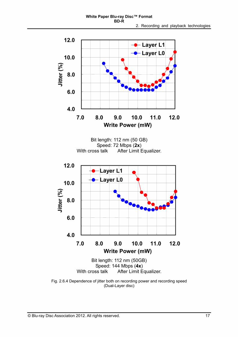
Fig. 2.6.4 shows the dependence of power and jitter on the recording rate from 36 Mbps to 144 Mbps.
The jitter value was less than 7 % even at the user recording rate of 144 Mbps.
4.0
6.0
8.0
10.0
12.0
7.0 8.0 9.0 10.0 11.0 12.0Write Power (mW)
Jitt
er (
%)
Layer L0Layer L1
Bit length: 112 nm (50 GB) Speed: 36 Mbps (1x)
With cross talk After Limit Equalizer
White Paper Blu-ray Disc™ Format BD-R
2. Recording and playback technologies
© Blu-ray Disc Association 2012. All rights reserved. 17
4.0
6.0
8.0
10.0
12.0
7.0 8.0 9.0 10.0 11.0 12.0Write Power (mW)
Jitt
er (
%)
Layer L0
Layer L1
Bit length: 112 nm (50 GB) Speed: 72 Mbps (2x)
With cross talk After Limit Equalizer.
4.0
6.0
8.0
10.0
12.0
7.0 8.0 9.0 10.0 11.0 12.0Write Power (mW)
Jitt
er (
%)
Layer L0
Layer L1
Bit length: 112 nm (50GB)
Speed: 144 Mbps (4x) With cross talk After Limit Equalizer.
Fig. 2.6.4 Dependence of jitter both on recording power and recording speed
(Dual-Layer disc)

White Paper Blu-ray Disc™ Format BD-R
2. Recording and playback technologies
18 © Blu-ray Disc Association 2012. All rights reserved.
As previously stated, the N/2 write strategy improves write quality at higher recording speeds. Fig..2.6.5 shows measurement results comparing the N-1 writing strategy and N/2 writing strategy using organic materials recorded at 72 Mbps (2X). In Fig. 2.6.5, the recording power versus jitter is shown with the results of Conventional Equalizer and Limit Equalizer. These results demonstrate wider power margins using the N/2 write strategy compared to the N-1 write strategy.
(a) N-1 writing strategy (b) N/2 writing strategy
Fig. 2.6.5 Dependence of jitter on recording power, writing strategy, and read equalizer
4
8
12
16
20
5 6 7 8 9 10 11 12
Pw (mW)
Jitte
r (%
)
CEQ
LEQ
4
8
12
16
20
5 6 7 8 9 10 11 12
Pw (mW)
Jitte
r (%
)
CEQ
LEQ

White Paper Blu-ray Disc™ Format BD-R
3. BDXL™ technologies
© Blu-ray Disc Association 2012. All rights reserved. 19
3. BDXL™ technologies BDXL™ technologies were developed to store a huge capacity of data in order to meet a rapidly
increasing demand for both professional usage and consumer production. In Blu-ray Disc™ Recordable Format (BDXL™) format both TL of 100 GB capacity and QL of 128 GB capacity were defined reflecting conventional media manufacturing technologies. In this chapter the following items are described, main parameters, disc structure, write strategy and Extended Adaptive Mark Compensation and i-MLSE (Integrated-Maximum-Likelihood-Sequence-Error-Estimation Technology.
3.1. Main parameters
Table 3.1.1. shows the main parameters of BD-R, including for both TL of 100 GB capacity and QL of 128 GB capacity format, main difference with legacy format are Cover-Layer-thickness distribution, capacity per layer, minimum-Mark length and evaluation index for signal quality. For both TL and QL 2X and 4X recording of 72~144 Mbps user transfer rate are specified.
BD-R
SL DL TL QL
Capacity 25 GB 50 GB 100 GB 128 GB Wavelength (λ) of laser
diode 405 nm
N.A. of objective lens 0.85
Cover-Layer thickness 100 μm 100 μm
(Layer L0) 75 μm
(Layer L1)
100 μm (Layer L0)
75 μm (Layer L1)
57 μm (Layer L2)
100 μm (Layer L0) 84.5 μm
(Layer L1) 65 μm
(Layer L2) 53.5 μm (Layer L3)
Capacity per layer 25 GB 25 GB 33.3 GB 32 GB Track format On-Groove
Address method MSK (Minimum-Shift Keying) & STW (Saw-Tooth Wobble) Rotation CLV
Track Pitch 0.32 μm Channel modulation 17PP
minimum-Mark length 149 nm 112 nm 117 nm Total efficiency 81.7%
User-Data transfer-rate 36 – 216 Mbps 72 – 144 Mbps Signal quality evaluation
index Limit Equalizer jitter i-MLSE using PR(1,2,2,2,1)
Write speed for media 1x, 2x, 4x (Optional), 6x (Optional) 2x, 4x
Table 3.1.1 Main parameters 3.2. Disc Structure
The disc structures of BD-R TL (Triple-Layer)/QL (Quadruple-Layer) discs are decided taking account of the following conditions;
To keep the basic concept of Blu-ray Disc™ format. Cover Layer should be as thick as possible to be durable against dust, scratch and finger prints.
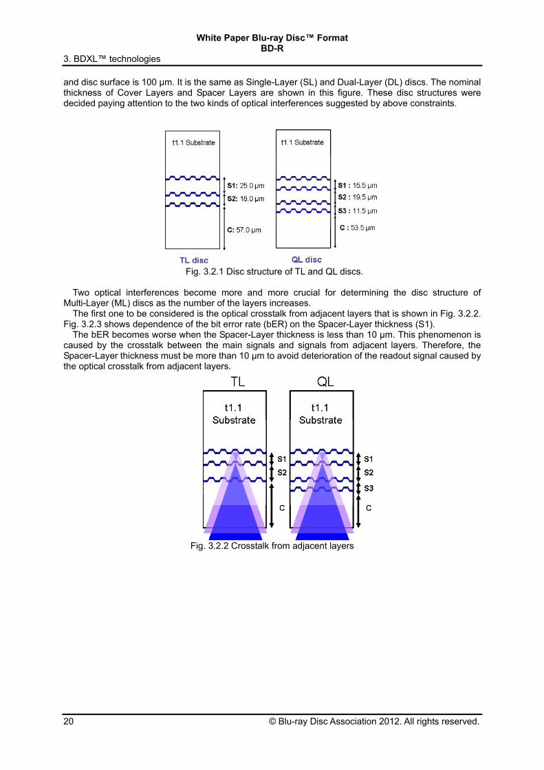
Fig. 3.2.1 shows an example of disc structure of a TL and a QL disc. The distance between Layer L0
White Paper Blu-ray Disc™ Format BD-R
3. BDXL™ technologies
20 © Blu-ray Disc Association 2012. All rights reserved.
and disc surface is 100 µm. It is the same as Single-Layer (SL) and Dual-Layer (DL) discs. The nominal thickness of Cover Layers and Spacer Layers are shown in this figure. These disc structures were decided paying attention to the two kinds of optical interferences suggested by above constraints.
Fig. 3.2.1 Disc structure of TL and QL discs.
Two optical interferences become more and more crucial for determining the disc structure of
Multi-Layer (ML) discs as the number of the layers increases. The first one to be considered is the optical crosstalk from adjacent layers that is shown in Fig. 3.2.2.
Fig. 3.2.3 shows dependence of the bit error rate (bER) on the Spacer-Layer thickness (S1). The bER becomes worse when the Spacer-Layer thickness is less than 10 µm. This phenomenon is
caused by the crosstalk between the main signals and signals from adjacent layers. Therefore, the Spacer-Layer thickness must be more than 10 µm to avoid deterioration of the readout signal caused by the optical crosstalk from adjacent layers.
Fig. 3.2.2 Crosstalk from adjacent layers

White Paper Blu-ray Disc™ Format BD-R
3. BDXL™ technologies
© Blu-ray Disc Association 2012. All rights reserved. 21
Fig. 3.2.3 Bit error rate dependence of Spacer Layer thickness.
The second one is the optical Inter-Layer interference. Fig. 3.2.4 shows the influence of optical path
difference between the main signal light and uninvited three-times-reflected signal light. Red dotted lines show the three-times-reflected lights. These lights are very weak. But once they focus on the photo detector, they interfere with the main signal. Fig. 3.2.5 shows the influence of the difference in the thickness between Spacer Layer (S1) and Spacer Layer (S2) on the readout signal. The disturbances are observed in the readout signal when the difference in the thickness of S1 and S2 becomes less than 1 µm. This optical Inter-Layer Interference occurs in any combination of thickness differences among Cover Layer and Spacer Layers.
Fig. 3.2.4 Optical Inter-Layer Interference.

White Paper Blu-ray Disc™ Format BD-R
3. BDXL™ technologies
22 © Blu-ray Disc Association 2012. All rights reserved.
Fig. 3.2.5 Influence of optical path difference between signal light and three-times-reflected signal light on readout signal.
Judging from above experimental results and presupposition of keeping basic concept of Blu-ray Disc™ format, disc structure of TL/QL discs are determined as follows;
Total thickness of Cover Layer and Spacer Layers shall be 100 µm Thickness of Spacer Layers shall be more than 10 µm Differences in thickness among Spacer Layers and Cover Layer shall be more than 1 µm Thickness of Cover Layer should be as thick as possible so that above conditions are fulfilled
The examples of disc structure shown in Fig. 3.2.1 fulfils above conditions.

White Paper Blu-ray Disc™ Format BD-R
3. BDXL™ technologies
© Blu-ray Disc Association 2012. All rights reserved. 23
3.3. Write strategy and Extended Adaptive Mark Compensation Two types of Write strategies are defined in the Blu-ray Disc™ Recordable format (BDXLTM); Extended N-1 write strategy and Extended Castle write strategy are applied for the discs. These write
strategies are based on N-1 write strategy and Castle write strategy respectively. As the recording density of BDXLTM is higher, a Mark/Space variation matrix is extended to 4 Marks x 4 Spaces to cancel Inter-Symbol Interference between Recording Marks. And Space adaptive parameters are expanded from only preceding Spaces to preceding and succeeding Spaces.
In accordance with the characteristics of each Recording Layer of a disc, a disc manufacturer determines the write strategy parameters and embeds them in the HF modulated Groove Area and the Wobbled Groove Address of the disc. 3.3.1 Extended N-1 write strategy
Fig. 3.3.1.1 schematically shows Extended N-1 write strategy which comprises pulse-modulated recording waveforms with four power levels of PW, PBW, PC and PS. Ttop denotes the duration of the first pulse, dTtop the start time offset of the first pulse from its reference position, TMP the duration of all following pulses except the last pulse, TLP the duration of the last pulse, dTLP the start time offset of the last pulse and dTS the start time offset of the Space level from its reference position. dTLP is added to control a trailing Mark edge position more precisely. The other parameters are the same as conventional N-1 write strategy. Fig. 3.3.1.1 shows an example of the write pulse waveform of a 4T Mark. The write pulse offsets (dTtop, dTLP and dTS), the write pulse duration (Ttop, TMP and TLP) and the power levels (PW, PBW, PC and PS) are shown. To control Mark edge positions precisely, each parameter (dTtop, Ttop, TMP, dTLP, TLP or dTS) is defined in 1/16 of the Channel-clock resolution.
dTLP
4T
PW
PS
NRZI
Tw
dTtop
Ttop TMP
dTS PBW
TLP
PC
Fig. 3.3.1.1 Extended N-1 write strategy
3.3.2 Extended Castle write strategy
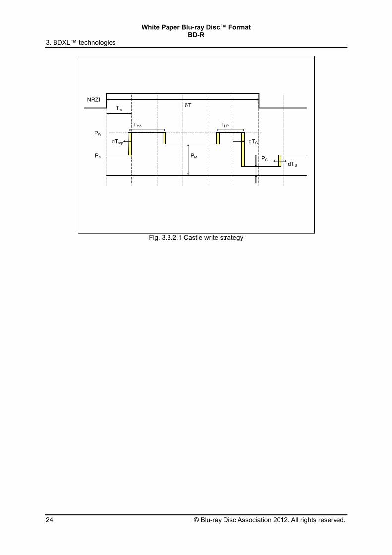
Fig. 3.3.2.1 schematically shows the Extended Castle write strategy which comprises pulse-modulated recording waveforms with four power levels of PW, PM, PC and PS. All parameters are the same as conventional Castle write strategy. Ttop denotes the duration of the first pulse, dTtop the start time offset of the first pulse from its reference position, dTC the start time offset of the cooling pulse except the 2T write pulse, TLP the duration of the last pulse, and dTS the start time offset of the Space level from its reference position. Fig.3.3.2.1 shows an example of the write pulse waveform of 6T Mark. The write pulse offsets (dTtop, dTC and dTS), the write pulse duration (Ttop and TLP), and the power levels (PW, PM, PC and PS) are shown. To control Mark edge positions precisely, each parameter (dTtop, Ttop, dTC, TLP or dTS) is defined by 1/16 of the Channel-clock resolution.
White Paper Blu-ray Disc™ Format BD-R
3. BDXL™ technologies
24 © Blu-ray Disc Association 2012. All rights reserved.
PMPS
6T
dTtop
PW
NRZI
Tw
Ttop
dTS PC
TLP
dTC
Fig. 3.3.2.1 Castle write strategy

White Paper Blu-ray Disc™ Format BD-R
3. BDXL™ technologies
© Blu-ray Disc Association 2012. All rights reserved. 25
3.4. i-MLSE technology Introduction
In Blu-ray Disc™ Recordable Format (BDXL™) the capacity per layer is raised up to 33.4 GB or 32.0 GB only by increasing the linear density. As a result, in BDXL™, the Inter-Symbol-Interference (ISI) of the readout signal becomes much stronger compared to the prior format that allows just 25 GB per layer. Therefore the readout signalprocessing needs to be improved. Also, the prior signal quality evaluation method using the Limit Equalizer technology has turned out to be no longer applicable.Integrated-Maximum-Likelihood-Sequence-Error-Estimation (i-MLSE), which is an alternative signal quality evaluation method for BDXL™, was newly developed and retains the stability and the precision in such a severe ISI condition of BDXL™. The evaluation method of i-MLSE stands on the detection principle of the Viterbi-Algorithm (VA) in the Partial-Response-Maximum-Likelihood (PRML) readout signal processing. Additionally, some contrivances can be incorporated to achieve the better correlation with the Symbol-Error-Rate (SER). For example, the tendency of error occurrences with the PR(1,2,2,2,1)ML readout in the BDXL™ is considered. Another feature of i-MLSE is that the mathematical expression is the same as that of Time-Interval-Jitter (TI-Jitter or Jitter, simply), which is the prior signal quality evaluation method. Consequently, the behavior of i-MLSE is very similar to that of the TI-Jitter. This helps people who evaluate the BDXL™ discs or systems for the first time to comprehend the meaning of measured values obtained through i-MLSE because the TI-Jitter has been used so long since the era of CDs and is very familiar to them.
Fig. 3.4.1: i-MLSE and SER correlation
Basic theory of i-MLSE i-MLSE is calculated from Sequenced-Amplitude-Margin (SAM) that indicates the reliability of VA. SAM is an instantaneous value that is defined as the path-metric differences between the Maximum-Likelihood-path (ML-path: decoded result in VA) and the Second-Likelihood-path (2nd-path) as shown in the left side figure of Fig. 3.4.2. In VA the path that has the smallest path-metric survives as the more-likelihood path at every state to which several branches are inflowing, as shown in the right side trellis diagram of Fig. 3.4.2. Therefore, the detection reliability of VA can be quantified by how smaller the path-metric of the ML-path compared to the rivalry paths’ path-metric, in other words, how large the SAM value is.
Readout Skew RT: Radial-tilt TT: Tangential-tilt CT: Cover-Thickness error DEF: Defocus
This figure shows measurement results of i-MLSE and SER for BDXL™ discs under various kinds of readout conditions. All plots including different kinds of readout conditions are approximately on the same curve. In other words, well-matched correlation performance of i-MLSE is demonstrated here.
1.E-06
1.E-05
1.E-04
1.E-03
1.E-02
1.E-01
8 10 12 14 16 18 20
SER
i-MLSE(%)
RT
TT
CT
DEF

White Paper Blu-ray Disc™ Format BD-R
3. BDXL™ technologies
26 © Blu-ray Disc Association 2012. All rights reserved.
Fig. 3.4.2: Calculation of SAM value
Generally, readout waveforms are distributed around ideal waveforms (i.e., ML-paths). In these cases,
the distribution of SAM values is revealed to be approximately a normal distribution which means SAM value is almost equal to the square Euclidean distance between ML-path and 2nd-path. By fitting the SAM distribution to the normal distribution we can calculate the error rate from the probability of appearance of the region in which SAM < 0. If the SAM distribution can be approximated as a single normal distribution from the viewpoint of prediction of error occurrences, the evaluated value of i-MLSE can be defined in completely the same manner as in the prior TI-Jitter. But actually, there are several error-dominant patterns which have different Euclidean distances and different variances (i.e. plural different normal distributions) in BDXL™. Therefore, to quantify the signal quality by a single value, it is required to evaluate contributions of the estimated errors from plural distributions with different variance and different mean value. In i-MLSE three groups of error-patterns are evaluated as error-dominant patterns as shown in the Table 3.4.1.
Calculation of i-MLSE For simplifying the numerical expression, we define normalized-SAM (ξk) for SAM of the k-th error-pattern as follows;
2
2
2 k
kkk
d
dSAM (3.4.1)
, where dk
2 represents the square Euclidean distance of the k-th error-pattern. i-MLSE is calculated in the following three steps. In the first place, for the purpose of quantifying the
Group Name Group 14 Group 12A Group 12B
Error Mode One bit shift Single 2T shift Consecutive 2T shift
Euclidean Distance (dk) 14 12 12
Truth and Error Bit Pattern (example)
T: 000001111 E: 000011111
T: 00000110000 E: 00001100000
T: 0000011001111 E: 0000110011111
Table 3.4.1 Evaluating error-patterns of i-MLSE
S00
S01
S10
S11
S00
S01
S10
S11
0/0
1/1
1/4
0/3
S00
S01
S10
S11
0/0
1/4
0/3
S00
S01
S10
S11
0/0
1/4
0/3
1/1
1/1
Maximum Likelihood Path(Detected Path)
2nd Likelihood Path(False Path)
Left figure shows how to calculate the SAM value and right figure shows the trellis diagram of VA. Although PR(1,2,2,2,1)ML with d = 1 run-length limited (i.e., ten states) is employed in the BDXL™ specification, simpler PR(1,2,1)ML with d = 1 run-length limited (i.e., four states) is assumed in these figures for ease of understanding of the concept of SAM.
3
1
23
1
2
iikik
iikik xTxFSAM

White Paper Blu-ray Disc™ Format BD-R
3. BDXL™ technologies
© Blu-ray Disc Association 2012. All rights reserved. 27
quality of the signal, mean value (ηk) of the minus side of ξk distribution with respect to its mean value (μk) is calculated (Fig. 3.4.3). Under the assumption of the normal distribution for ξk, the estimated bER of the k-th error-pattern (ebERk) and ηk has the relationship as follows;
kk
kkkk erfc
WebER
2
21
2 (3.4.2)
, where ρk denotes the frequency of the k-th error-pattern, Wk denotes the Hamming distance of the k-th error-pattern and erfc( ) denotes the complimentary error function. Then, the total estimated bER (ebERtotal) is obtained by adding each ebERk for all error-patterns. This manner is very straightforward, but the integration among the different error-patterns can be performed most accurately. Finally, i-MLSE (σi-MLSE) is obtained by converting ebERtotal to the equivalent normalized standard deviation (i.e. the jitter value) by following equation;
MLSEi
totaltotal
1
total
total1MLSEi
σ22
1erfc
2
ρbER
ρ
bER2erfc22σ e
e (3.4.3)
, where erfc-1( ) denotes the operation of the invert function of the complimentary error function.
μ
0
η=E[ζ|ζ<μ]
Fig.3.4.3: Signal quality estimation by one-sided mean value of the normalized SAM distribution
White Paper Blu-ray Disc™ Format BD-R
4. Modulation Code and Error-Correction Code for BD
28 © Blu-ray Disc Association 2012. All rights reserved.
4. Modulation Code and Error-Correction Code for Blu-ray Disc™(BD) 4.1. Modulation Code What is a Modulation Code?
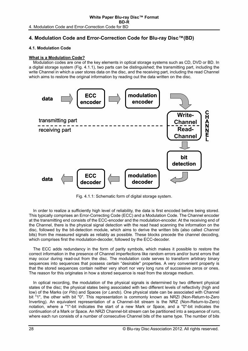
Modulation codes are one of the key elements in optical storage systems such as CD, DVD or BD. In a digital storage system (Fig. 4.1.1), two parts can be distinguished; the transmitting part, including the write Channel in which a user stores data on the disc, and the receiving part, including the read Channel which aims to restore the original information by reading out the data written on the disc.
ECCencoder
modulationencoder
CHANNEL
data
WRITEchannel
READchannel
bitdetection
modulationdecoderdata
ECCdecoder
transmitting part
receiving part
ECCencoder
modulationencoder
CHANNEL
data
WRITEchannel
READchannel
bitdetection
modulationdecoderdata
ECCdecoder
transmitting part
receiving part
Write-Channel
Read-Channel
Fig. 4.1.1: Schematic form of digital storage system.
In order to realize a sufficiently high level of reliability, the data is first encoded before being stored. This typically comprises an Error-Correcting Code (ECC) and a Modulation Code. The Channel encoder at the transmitting end consists of the ECC-encoder and the modulation-encoder. At the receiving end of the Channel, there is the physical signal detection with the read head scanning the information on the disc, followed by the bit-detection module, which aims to derive the written bits (also called Channel bits) from the measured signals as reliably as possible. These blocks precede the channel decoding, which comprises first the modulation-decoder, followed by the ECC-decoder.
The ECC adds redundancy in the form of parity symbols, which makes it possible to restore the
correct information in the presence of Channel imperfections like random errors and/or burst errors that may occur during read-out from the disc. The modulation code serves to transform arbitrary binary sequences into sequences that possess certain “desirable'' properties. A very convenient property is that the stored sequences contain neither very short nor very long runs of successive zeros or ones. The reason for this originates in how a stored sequence is read from the storage medium.
In optical recording, the modulation of the physical signals is determined by two different physical
states of the disc; the physical states being associated with two different levels of reflectivity (high and low) of the Marks (or Pits) and Spaces (or Lands). One physical state can be associated with Channel bit "1", the other with bit "0". This representation is commonly known as NRZI (Non-Return-to-Zero Inverting). An equivalent representation of a Channel–bit stream is the NRZ (Non-Return-to-Zero) notation, where a "1"-bit indicates the start of a new Mark or Space, and a "0"-bit indicates the continuation of a Mark or Space. An NRZI Channel-bit stream can be partitioned into a sequence of runs, where each run consists of a number of consecutive Channel bits of the same type. The number of bits
White Paper Blu-ray Disc™ Format BD-R 4. Modulation Code and Error-Correction Code for BD
© Blu-ray Disc Association 2012. All rights reserved. 29
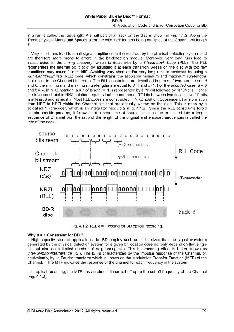
in a run is called the run-length. A small part of a Track on the disc is shown in Fig. 4.1.2. Along the Track, physical Marks and Spaces alternate with their lengths being multiples of the Channel-bit length T.
Very short runs lead to small signal amplitudes in the read-out by the physical detection system and
are therefore more prone to errors in the bit-detection module. Moreover, very long runs lead to inaccuracies in the timing recovery, which is dealt with by a Phase-Lock Loop (PLL). The PLL regenerates the internal bit "clock" by adjusting it at each transition. Areas on the disc with too few transitions may cause "clock-drift". Avoiding very short and/or very long runs is achieved by using a Run-Length-Limited (RLL) code, which constrains the allowable minimum and maximum run-lengths that occur in the Channel-bit stream. The RLL constraints are described in terms of two parameters, d and k: the minimum and maximum run-lengths are equal to d+1 and k+1. For the uncoded case, d = 0 and k = . In NRZ notation, a run of length m+1 is represented by a "1"-bit followed by m "0"-bits. Hence the (d,k)-constraint in NRZ notation requires that the number of "0"-bits between two successive "1"-bits is at least d and at most k. Most RLL codes are constructed in NRZ notation. Subsequent transformation from NRZ to NRZI yields the Channel bits that are actually written on the disc. This is done by a so-called 1T-precoder, which is an integrator modulo 2 (Fig. 4.1.2). Since the RLL constraints forbid certain specific patterns, it follows that a sequence of source bits must be translated into a longer sequence of Channel bits; the ratio of the length of the original and encoded sequences is called the rate of the code.
Channel-bit stream
source bitstream
NRZ (d,k)
NRZI (RLL)
BD-R disc
Fig. 4.1.2: RLL d = 1 coding for BD optical recording. Why d = 1 Constraint for BD ?
High-capacity storage applications like BD employ such small bit sizes that the signal waveform generated by the physical detection system for a given bit location does not only depend on that single bit, but also on a limited number of neighboring bits. This bit-smearing effect is better known as Inter-Symbol-Interference (ISI). The ISI is characterized by the impulse response of the Channel, or, equivalently, by its Fourier transform which is known as the Modulation Transfer Function (MTF) of the Channel. The MTF indicates the response of the channel for each frequency in the system.
In optical recording, the MTF has an almost linear roll-off up to the cut-off frequency of the Channel
(Fig. 4.1.3).

White Paper Blu-ray Disc™ Format BD-R
4. Modulation Code and Error-Correction Code for BD
30 © Blu-ray Disc Association 2012. All rights reserved.
MTFd = 1d = 2
MTFd = 1d = 2
Fig. 4.1.3: MTF for optical recording Channel as function of frequency (in arbitrary units, with the cut-off at “1”) with frequencies of pure tones … | nTd | nTd | … superimposed.
Therefore, short run-lengths in the Channel-bit stream, which lead to high-frequency signals, suffer most from ISI and are thus more prone to errors during read-out. One of the purposes of Run-Length-Limited coding is to impose constraints that do not allow these high-frequent bit-sequences. To illustrate this principle, we discuss the effect of employing three different d-constraints, for d = 0 (uncoded), d = 1, and d = 2, while maintaining the same density of source bits on the disc. So let T denote the common physical size of a source bit. Using a d-constrained code at a rate Rd, the physical Channel-bit size Td will necessarily satisfy Td = Rd T. Fig. 3.1.4 shows the respective Channel-bit lengths and the highest frequency in the system (which correspond to an alternation of runs of minimum run-length). Here, we of course have R0 = 1 in the uncoded case. Furthermore, we assume that practical codes are used that have rates R1 = 2/3 and R2 = 1/2, which are close to the maximal achievable code rates of 0.6942 and 0.5515, respectively. The minimum run-length for d = 1 equals 2T1 = 4/3T, which is larger than the minimum run-length T for d = 0; also, the minimum run-length for d = 2 amounts to 3T2 = 3/2T, which is larger than the minimum run-length for d = 1. Consequently, the highest frequencies fd in the system are
.3
1
6
1
8
3
4
1
2
1
2
2
1
10 TTRf
TTRf
Tf
This relation reveals the increasing low-pass character of the code for increasing d constraint, which is the major attractiveness of RLL coding. This becomes also clear from Fig. 3.1.3, which shows the MTF with the frequencies of the pure tones … | nTd | nTd | nTd | … for n = d+1, d+2, … superimposed.
However, note that the Channel-bit length (or timing window) decreases for increasing d constraint,
which leads to a greater sensitivity with respect to jitter or Mark-edge noise in the system. This counteracting effect favors the use of a lower d constraint. The practical choice for the d = 1 constraint in BD is the optimal compromise between mark-edge noise (lower d) and ISI (higher d). The k-constraint has been chosen to be k = 7, from which the acronym “17PP” has been derived.

White Paper Blu-ray Disc™ Format BD-R 4. Modulation Code and Error-Correction Code for BD
© Blu-ray Disc Association 2012. All rights reserved. 31
d=0• uncoded• Minimum Runlength :1T
T
channelbit length
min.runlength
d=2• Rate R2 = T2 / T = 1/2• Minimum Runlength : 3T2
3 T2T2
d=1• Rate R1 = T1 / T = 2/3• Minimum Runlength : 2T1
2 T1T1
d=0• uncoded• Minimum Runlength :1T
T
channelbit length
min.runlength
d=2• Rate R2 = T2 / T = 1/2• Minimum Runlength : 3T2
3 T2T2
d=1• Rate R1 = T1 / T = 2/3• Minimum Runlength : 2T1
2 T1T1
d = 0· uncoded· Minimum Run-length1T
d = 1· Rate R1 = T1 / T = 2/3· Minimum Run-length2T1
d = 2· Rate R2 = T2 / T = 1/2· Minimum Run-length3T2
min.
run-length
Channel-
bit length
Fig. 4.1.4 Channel-bit length and minimum run-length for different d constraints at same recording capacity.
Why 17PP “Parity-Preserving” Code?
All RLL codes used in optical recording are dc-free, that is, they have almost no content at low frequencies. We consider NRZI Channel bits bi with bipolar values ±1. A sequence b1, b2, … is called dc-free if its Running Digital Sum (RDS; the integral of the bipolar Channel–bit stream)
i
jji
bRDS
takes on only a limited number of different values. Then, the power spectral density function vanishes at DC. The dc-free property is needed for a number of reasons; (i) for separation of the data signal from disc noise such as fingerprints or dust, (ii) for control of the slicer level, and (iii) for the servo systems.
We shall now discuss a general method to achieve dc-control in RLL sequences. dc-control is performed via control of the Running Digital Sum (RDS). A very useful concept herein is the parity, the number of ones modulo 2, of a sequence of bits. Recall that an NRZ "1"-bit indicates the start of a new run in the (bipolar) NRZI bitstream. Hence, because of the 1T-precoder between NRZ and NRZI Channel-bit streams, each "1"-bit in the NRZ Channel-bit stream changes the polarity in the corresponding NRZI bitstream. Consequently, an odd number of ones in a segment of the NRZ Channel-bit stream reverses the NRZI polarity after that segment while an even number of ones leaves the polarity unchanged.
The above observation can be used for dc-control as follows. Suppose that for a certain segment of
the NRZ Channel-bit stream, we can choose between two candidate sequences, one with parity "0", the other with parity "1". Then the part of the NRZI Channel-bit stream after this segment will have a contribution to the RDS where the sign depends on which of the two sequences is chosen. The best choice is of course the one that keeps the value of the RDS as close to zero as possible. We refer to these segments as dc-control segments. In order to realize dc-control, we have to insert dc-control segments at regular positions in the bit stream. Such positions are referred to as dc-control points.
A clever and efficient method for dc-control, as used in the 17PP modulation code of BD, is via the
use of a Parity-Preserving code (Fig. 4.1.5). Such a code preserves the parity upon RLL encoding, that is, the parity of a source word is identical to the parity of the corresponding channel word. Single dc-control bits are inserted (at dc-control points) in the source bitstream. Changing a dc-control bit from 0 to 1 changes the parity in the source bitstream and hence also in the NRZ Channel-bit stream: this property enables the selection of the polarity of the NRZI Channel-bit stream, and thus allows for dc-control. The overhead required for each dc-control point in the 17PP code is exactly equal to one source bit, which amounts to the equivalent of 1.5 Channel bits. This makes the 17PP Parity-Preserving

White Paper Blu-ray Disc™ Format BD-R
4. Modulation Code and Error-Correction Code for BD
32 © Blu-ray Disc Association 2012. All rights reserved.
d = 1 code 25% more efficient at each dc-control point, compared with conventional methods for dc control.
Choose “best”
DC-free
Channel-bit stream
...
...
DC-control points
source bitstream
insertion of DC-bits
...
Parity-PreservingModulation Code
DC DC1/0
...
1/0
polarity “+”
polarity “-”or
= source bit
= channel bit
...
...
DC-control points
source bitstream
insertion of DC-bits
Parity-PreservingModulation Code
DC DC1/0
...
DC-bit = 0-
DC-bit = 1
1/0
Choose “best”
DC-free
Channel-bit stream
...
...
DC-control points
source bitstream
insertion of DC-bits
...
Parity-PreservingModulation Code
DC DC1/0
...
1/0
polarity “+”
polarity “-”or
= source bit
= channel bit
= source bit
= channel bit
...
...
DC-control points
source bitstream
insertion of DC-bits
Parity-PreservingModulation Code
DC DC1/0
...
DC-bit = 0-DC-bit = 0-
DC-bit = 1DC-bit = 1
1/0
Fig. 4.1.5: Principle of dc-control via Parity-Preserving modulation code.
The 17PP code has been designed with one additional favorable property in the sense that it prohibits
the occurrence of a large number of consecutive minimum run-lengths (2T) which is known as the RMTR (Repeated Minimum-Transition Run-length) constraint. The minimum run-lengths lead to low signal levels, and by restricting their occurrence, the read-out performance is improved. 4.2 Error-Correction format
In optical recording roughly two types of errors can be distinguished: single (or random) errors and burst errors. Single errors are caused by noise in combination with other sources of signal deterioration such as tilt of the disc or defocus of the laser spot on the disc. They are called single errors because they only affect one or two bytes. Burst errors are caused by defects on the disc surface like scratches, dust, fingerprints etc.
The Error-Correction system should be adapted to the physical properties of the medium on which the
data is stored. Blu-ray Disc™ is, due to its small spot, the thin Cover layer and the high numerical aperture, more sensitive to burst errors than for instance the DVD system. The same defect on a Blu-ray Disc™ will affect more data bits than on a DVD disc. The Error-Correction system of Blu-ray Disc™ should therefore be able to cope very well with long burst errors.
The maximum number of errors that can be corrected depends on the number of parity symbols
added. For each two parity symbols added, one error can be corrected. This assumes nothing is known beforehand about the error. If the location of an error within the code word is known beforehand, only the erased value of the error has to be calculated. For each parity symbol added, one erased value can be calculated, i.e. one erasure can be corrected. So it is advantageous for the Error Corrector to use prior knowledge of the error locations in the decoding process. Due to the nature of the errors, this is not possible for random errors, but it is very well possible for burst errors. It requires a burst indicator mechanism that can detect bursts of errors before the correction starts.
White Paper Blu-ray Disc™ Format BD-R 4. Modulation Code and Error-Correction Code for BD
© Blu-ray Disc Association 2012. All rights reserved. 33
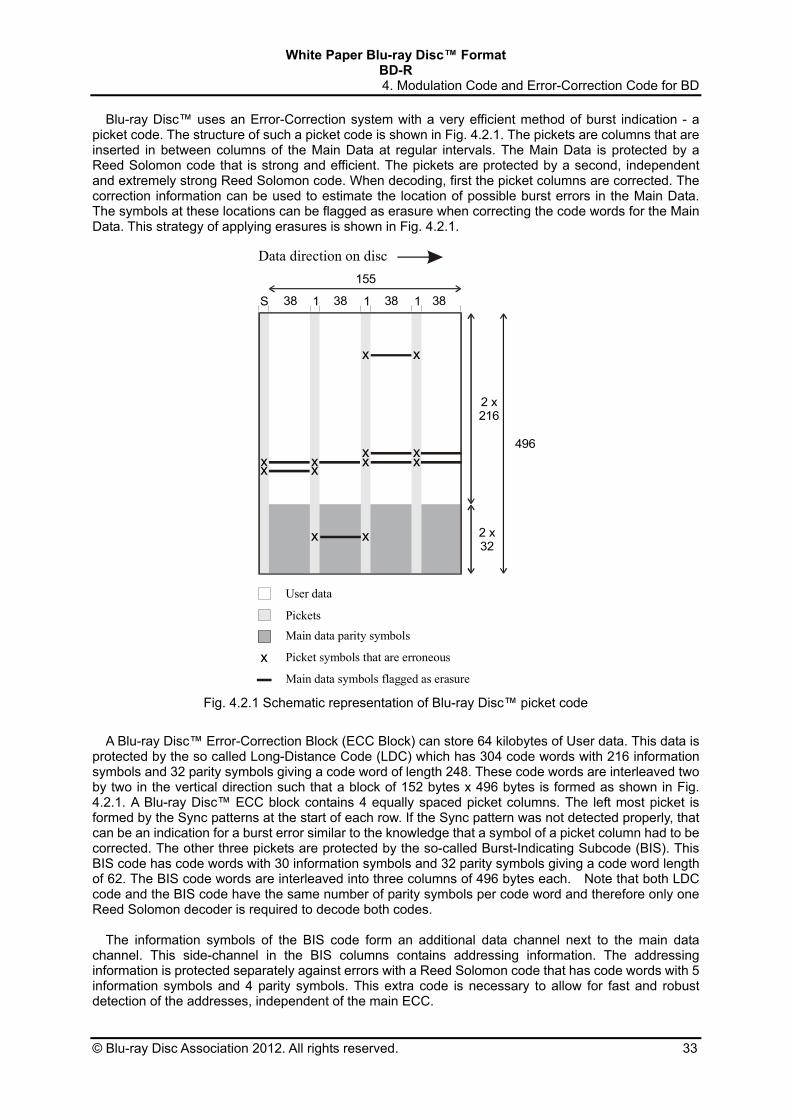
Blu-ray Disc™ uses an Error-Correction system with a very efficient method of burst indication - a picket code. The structure of such a picket code is shown in Fig. 4.2.1. The pickets are columns that are inserted in between columns of the Main Data at regular intervals. The Main Data is protected by a Reed Solomon code that is strong and efficient. The pickets are protected by a second, independent and extremely strong Reed Solomon code. When decoding, first the picket columns are corrected. The correction information can be used to estimate the location of possible burst errors in the Main Data. The symbols at these locations can be flagged as erasure when correcting the code words for the Main Data. This strategy of applying erasures is shown in Fig. 4.2.1.
x
x x
xxxxxxx
x x
Data direction on disc
x Picket symbols that are erroneous
Main data symbols flagged as erasure
Pickets
User data
Main data parity symbols
S 138 38
155
38
496
2 x216
2 x32
381 1
Fig. 4.2.1 Schematic representation of Blu-ray Disc™ picket code
A Blu-ray Disc™ Error-Correction Block (ECC Block) can store 64 kilobytes of User data. This data is
protected by the so called Long-Distance Code (LDC) which has 304 code words with 216 information symbols and 32 parity symbols giving a code word of length 248. These code words are interleaved two by two in the vertical direction such that a block of 152 bytes x 496 bytes is formed as shown in Fig. 4.2.1. A Blu-ray Disc™ ECC block contains 4 equally spaced picket columns. The left most picket is formed by the Sync patterns at the start of each row. If the Sync pattern was not detected properly, that can be an indication for a burst error similar to the knowledge that a symbol of a picket column had to be corrected. The other three pickets are protected by the so-called Burst-Indicating Subcode (BIS). This BIS code has code words with 30 information symbols and 32 parity symbols giving a code word length of 62. The BIS code words are interleaved into three columns of 496 bytes each. Note that both LDC code and the BIS code have the same number of parity symbols per code word and therefore only one Reed Solomon decoder is required to decode both codes.
The information symbols of the BIS code form an additional data channel next to the main data
channel. This side-channel in the BIS columns contains addressing information. The addressing information is protected separately against errors with a Reed Solomon code that has code words with 5 information symbols and 4 parity symbols. This extra code is necessary to allow for fast and robust detection of the addresses, independent of the main ECC.

White Paper Blu-ray Disc™ Format BD-R
5. Address format using Groove Wobbles
34 © Blu-ray Disc Association 2012. All rights reserved.
5. Address format using Groove Wobbles Address format using Wobbled Groove
The Blu-ray™ Recordable disc has the exact same address format as that of the Blu-ray™ Rewritable disc. The disc contains a single spiral Wobbled (slight radial deviations from a true spiral) Groove used to perform tracking control and generation of write-timing for the drive. In addition, the Wobbled Groove contains embedded addressing and auxiliary information on the unrecorded Track. The address information identifies Track positions across the entire Grooved Area on the disc while the auxiliary information contains information inherent to the disc. For embedding this information, the Groove of the BD-R is modulated by Wobbling. The amplitude of the Wobble modulation is approximately ± 10 nm in a radial direction of the disc.
The BD-R writes very small high-density Marks with precision. For this reason, the disc drive
requires a highly stable and accurate recording clock signal. Therefore, the fundamental frequency component of Wobbles is a single frequency and the Groove is smooth and continuous. Given a single frequency, it is possible to generate a stable writing clock signal with ease from filtered Wobble components. Since User Data is always written in sync with the Wobbles, the length of one Wobble period is always proportional to the Mark length of written data. Thus the disc capacity is naturally determined by the length of the Wobble period formed on the disc. (For example, the capacity of a Single-Layer disc is 25.0 GB if the Wobble length is 5.14 μm, and 27.0 GB if the Wobble length is 4.76 μm, corresponding to exactly 69 Channel bits per Wobble period.)
Some single frequency-based Wobbles are further modulated in order to provide additional timing
and address information. This modulation must be robust against various types of distortion inherent to optical discs. Roughly classified, the following four distortions can occur on optical discs.
(1) Noise: Groove noise is caused by the Recording Stack and the rough formation of tracking
Groove. Data crosstalk noise is caused by Recorded Data. (2) Wobble shift: A phenomenon where the position of Wobble detected by the disc drive relatively
shifts from the normal position, resulting in decreased detection sensitivity. The Wobble shift tends to occur immediately after seeking.
(3) Wobble beat: The Wobble beat is produced by Wobble crosstalk of adjacent Tracks. The cause of the Wobble beat is a shift in angular frequency of adjacent Wobbles in the CLV format.
(4) Defect: A local flaw such as dust or scratch on disc surface.
A fundamental requirement in the development of the address format of BD was to take measures against all of these different types of distortions. Consequently, BD uses a combination of two different Wobble modulation systems in a configuration producing synergistic effects without adverse side effects. This combination satisfies all the anti-distortion requirements, an outcome that is difficult to achieve using only one modulation system. More specifically, BD has adopted a completely innovative address system combining Minimum-Shift Keying (MSK) modulation and Saw-Tooth Wobble (STW) technology, as explained later. The address format making use of MSK and STW is highly stable against the four types of distortion owing to each basic shape of the wobble address format. Configuration of ADIP Unit and Wobble Groove shapes
Groove Wobbles, formed spirally on disc, can be divided into successive units of address information bits embedded in the Wobble, as shown in Fig. 5.1. These are known as the ADdress In Pre-Groove (ADIP) Unit. One ADIP Unit is comprised of 56 Wobbles. Fig. 5.2 shows a schematic diagram of the ADIP Unit expressing "ONE" and "ZERO" of one bit in address data by the MSK and STW combination.

White Paper Blu-ray Disc™ Format BD-R
5. Address format using Groove Wobbles
© Blu-ray Disc Association 2012. All rights reserved. 35
Caution; The amplitude of Wobbling is enhanced so that it helps understanding.
Track Pitch(0.32 m)
1 bit of address information = ADIP Unit(56 Wobble periods 0.3 mm)
Wobble period( 5 m)
groove
Fig. 5.1
For the tracking of the laser beam, continues spiral Groove is formed on the disc.The Groove is modulated with Wobbling by cosine, MSK and STW in order to store the address information.
Blu-ray DiscTM
5530 18
data_0
data_1
Monotone Wobbles ; cos(t) STW0 Wobbles ; cos(t)-0.25sin(2t)
STW1 Wobbles ; cos(t)+0.25sin(2t)MSK Wobbles ; cos(1.5t), -cos(t), -cos(1.5t)
Wobble # 12
Schematic representation of the ADIP Units for Data_0 and Data_1. An ADIP Unit has a length of 56 Wobbles, which contain the first MSK Mark for bit sync, the second MSK Mark characterized by the difference of the position and 37 STWs characterized by the difference of the slope for Data_0 or Data_1.
Fig. 5.2

White Paper Blu-ray Disc™ Format BD-R
5. Address format using Groove Wobbles
36 © Blu-ray Disc Association 2012. All rights reserved.
The basic Units of MSK and STW have the following shapes. The basic Unit of MSK Wobbles is
three Wobbles. The middle Wobble of the three has an inverted polarity in comparison with continuous cosine waves cos(ωt) (known as Monotone Wobble) and is sandwiched between cosine waves of a 1.5X frequency, cos(1.5ωt). MSK is made up of cosine instead of sine because, in the MSK modulation using phase inversion, smooth waveform connections will be achieved with adjacent Wobbles without a discontinuous section. As a result, MSK requires a small number of frequency bands. As MSK uses one type of waveform alone, differences in waveform position are used as information.
STW waveforms are classified into two types. The waveform of data ZERO has edges that rise
steeply towards the outer side of the disc and fall gently towards the inner side of the disc. Conversely, the edges of the waveform of data 1 rise gently and fall steeply. The shape resembles saw teeth and that is why STW was so named. Mathematically, STW is expressed by the addition of the fundamental wave cos(ωt) and the second harmonic sin(2ωt) with a quarter-amplitude. The polarity of the secondary sine component in the case of data ZERO is the inversion of data ONE. Characteristically, zero-cross points, as in the case of Monotone Wobbles, have no influence on the clock phase reproduced from the fundamental wave component. Although sharp saw teeth can be expressed by the incorporation of higher harmonic components, the limitation to the secondary component makes it possible to keep the required band narrow for the disc mastering unit and to prevent degradation in high-frequency components caused by other signals.
Every ADIP Unit starts with a MSK, as shown in Fig. 5.2. The starting MSK called "bit sync" serves
as an identifier for the ADIP start point. The difference in the position of the next MSK represents 0 or 1 of data. More specifically, there are successive Monotone Wobbles between the bit sync and the second MSK, the number being 11 for data 0 and 9 for data 1, giving a 2-Wobble difference in position. It should be noted that MSK utilizes local phase change of the fundamental wave. In other words, areas of no phase change must be predominant to generate a stable write clock and for Wobble detection. Those areas effectively use STW, for which the phase of the fundamental wave does not change. In an ADIP Unit, 37 Wobbles from the 18th to the 54th are modulated by STW. Wobbles representing data 0 have edges rising steeply, and those representing data 1 have edges rising gently and are provided extensively. In order to ensure increased address reliability, the same information is stored in a single ADIP Unit in different MSK and STW formats.
A series of 83 ADIP Units forms an ADIP word expressing an address. One ADIP word contains
12-bit auxiliary data, reference (explained later), Error-Correction Code, as well as 24-bit address information. The BD Wobble format allocates three ADIP words to each 64-Kbyte Recording Unit Block (RUB) of main data for writing. Detection Methods for and Characteristics of MSK and STW
The BD drive unit detects Wobble signals from Push-Pull signals. Fig. 5.3 shows an example of circuit configuration. The drive unit is allowed to use MSK and STW independently or simultaneously to identify ZERO or ONE of an ADIP Unit.
MSK and STW, although apparently different, can be detected using the same heterodyne circuits (consisting of a carrier multiplier, integrator, sample-and-hold, and comparator). Increased detection performance is achieved by a hybrid detection method in which integrals of MSK and STW are accumulated.
Their detection methods differ in that MSK uses the fundamental wave (957 KHz) as the carrier for
multiplication, while STW used the second harmonic (1,913 KHz). The only other difference is in the timing signal used to operate each circuit. MSK and STW are highly compatible with each other in terms of detection circuits.
MSK stores information in a local area making use of strong phase change of the fundamental wave and therefore has an excellent SNR. STW is not prone to performance degradation caused by positional shifts as its information is distributed in a wide area spanning 37 cycles. In contrast, MSK provides better position information as a bit sync for finding the head of an ADIP Unit. STW laid out in a wide area is insensitive and robust against local defects. An outcome of the combination of MSK and

White Paper Blu-ray Disc™ Format BD-R
5. Address format using Groove Wobbles
© Blu-ray Disc Association 2012. All rights reserved. 37
STW in an address format is the achievement of substantial robustness against different types of distortions, such as noise and defects, and satisfactory high performance for accurate positioning and against Wobble shifts.
Wobble signalfrom push-pull Integral
S&H
MSK+STW(Hybrid detection)
reset
sample
carrier ;
wobble#16.5
wobble#55
main component when MSK,second harmonic when STW
S&H MSK
sample
STW
Multiplier
ComparatorsSample & Hold
An example of the heterodyne detection circuit for the MSK marks and the STWs. Both of the MSK marks and STWs can be detected using the common circuit by only changing frequency of the carrier supplied to the multiplier.
Fig. 5.3
Reference ADIP Unit
Wobble beats, which are beats at the fundamental frequency of Wobbles, occur substantially as the Groove on BD is a narrow-pitched Groove. These beats modulate both the amplitude and phase of the detected single-frequency component. Consequently, detection quality of both MSK and STW degrades due to the beats. Hence the physical length of one Wobble cycle was optimized to minimize the influence of beats and was established to be equivalent to 69 writing Channel clock signals. Furthermore, reference ADIP Units, which are inserted at every 5 ADIP Units, can correct the influence of beats. The reference ADIP Unit is comprised of STW of data 0. Since the Unit is known to be 0 in advance, it becomes possible to correct a phase shift so that the detected value is precisely data 0. Reference: “Wobble-address format of the Blu-ray Disc”, S. Furumiya et al., JJAP, Vol. 42, No. 2B (February 2003)

White Paper Blu-ray Disc™ Format BD-R
6. Disc Management
38 © Blu-ray Disc Association 2012. All rights reserved.
6. Disc Management
The use of recordable DVD optical discs has become increasingly widespread because of their large capacity of up to 4.7 GB, cost effectiveness and good interchangeability. A blue laser design with 0.1 mm Cover thickness and Multi-Layer recording technology now expands this capacity to 100 GB over. Such high capacity media require an error free recording space and random recordability. A disc management system containing defect management and recording management has been developed for the BD-R disc. Defect management enables an error free recording space and logical overwrite (LOW), while recording management enables and controls either sequential recording or random recording on BD-R (see 6.2). This Logical OverWrite (LOW) feature simplifies file system designs by making Blu-ray™ Recordable discs behave similarly to Blu-ray™ Rewritable discs.
6.1. Defect Management and Logical Overwrite To provide an error free volume space to the file system, defect management methods have been
widely used for rewritable media. This part of the disc management system replaces defective Data Units with a correct version in a pre-assigned Spare Area. Such a replacement scheme has been carefully designed for BD-R taking into account the write-once characteristics of these media.
The BD-R disc has an Inner Spare Area (ISA) and Outer Spare Area (OSA) in each layer like BD-RE (Blu-ray Disc™ Rewritable) shown in Fig. 6.1.1. These areas are divided into Temporary Disc Management Areas (TDMAs) and available spare replacements. In general, one quarter of the Inner and Outer Spare Area is provided for TDMAs, leaving the remainder to replace defects. In addition, TDMAs are allocated in the Lead-in of Layer L0 and Lead-out of Layer L1. Temporary Disc Management Structures (TDMSs) are stored consecutively in the TDMAs. This construction allows many updates of the TDMS during use of the disc.(Fig. 6.1.2)
SpareArea
SpareArea
SpareArea
SpareArea
Layer L0
Layer L1
SpareArea
SpareArea
SpareArea
SpareArea
Layer L0
Layer L1
Fig. 6.1.1. Location of TDMAs on disc
A TDMS contains the basic disc management information. This consists of the Temporary Disc Definition Structure (TDDS), the Temporary Defect List (TDFL) and the recording management information. There are two mutually exclusive types of recording management information, SRRI and SBM. They will be explained in 6.2.
For quick accessing of the latest contents of a TDMS, the TDDS, which has pointers to the other
elements, is always recorded at the end of the TDMS at every update.

White Paper Blu-ray Disc™ Format BD-R
6. Disc Management
© Blu-ray Disc Association 2012. All rights reserved. 39
Fig. 6.1.2. TDMA contents.
The TDFL lists any defect locations and their corresponding replacement locations allocated by the defect management system. To reduce TDMA consumption, the TDFL is of variable size and does not have a list of usable spare locations. Rather, the TDDS contains the next available spare replacement location for each Spare Area.
At disc closure, the contents of the latest TDMS are copied into DMAs located at positions
corresponding to those in the BD-RE standard. Once this is done, because write-once recording on BD-R is permanent, it is impossible to modify the disc management information in the DMAs which contain the replacement information and the User Recorded Area. This feature can guard against unwanted modifications.
Since this defect management design for BD-R uses linear replacement, it is possible to employ it for
logical overwriting of already written User data, thus effectively mimicking a rewritable medium. Such logical overwriting (writing to the same LSN, but actually recording at a reassigned PSN by linear replacement) is treated in the similar way as defect management, i.e. the information about the redirections is stored in the same Defect List.(Fig. 6.1.3)
Fig. 6.1.3. LOW Replacement
Data A (La)
Physical Volume Space
Data A (Pa)
Logical Volume Space
Before LOW
Data A" (La)
Physical Volume Space
Data A (Pa)
Logical Volume Space
After LOW
Data A" update command at La
Data A" (Pb)
1. update by replacement2. Create Defect List: Pa -> Pb

White Paper Blu-ray Disc™ Format BD-R
6. Disc Management
40 © Blu-ray Disc Association 2012. All rights reserved.
6.2 Recording Management Legacy compatibility is one of the major goals of BD-R. To provide a compatible recording method to
legacy write-once media (e.g., CD-R, DVD-R, DVD+R) and to provide maximum recording compatibility among the BD disc family, the BD-R system provides two kinds of recording modes. They are Sequential Recording Mode and Random Recording Mode.
In the Sequential Recording Mode, existing sequential recording applications are easily modified for use with the BD-R disc. The BD-R drive makes use of a logical Track that is referred to as Sequential Recording Range (SRR) and logical sessions just like other sequential recording media, while still providing the flexibility of allowing simultaneous recording with up to sixteen open SRRs. This scheme is controlled with Sequential Recording Range Information (SRRI).
Unlike CD-R and other recordable optical media, for BD-R it is not required to fill up the Unrecorded Areas to make the disc readable by other BD drives such as BD-ROM. This feature will reduce the time for closure operation (i.e. Track/session/disc closing) in comparison to legacy sequential recording media. In addition, the linear replacement defect management scheme enables the logical overwrite of previously recorded User data on a BD-R disc.
One of the outstanding features of BD-R is the support of a Random Recording Mode. It is possible to record User Data randomly on a BD-R disc on a 64 KByte ECC Cluster basis. The BD-R drive applies a Space Bit Map (SBM) to manage Recorded/Unrecorded Areas during the Random Recording Mode. This Random Recording Mode in BD-R offers the same recording experience as for BD-RE.
Besides the provision of an error free volume space and a broad choice of recording modes, this design also creates an important improvement in the robustness of the disc management information structure. For correct retrieval of the User Data, additional information is provided to enable reconstruction methods designed to obtain the required information even in the case of possible damage to some of the disc management structures. Among this new information are an inconsistency flag for conformity checking, writing the defective Cluster address in the replacement Cluster and a padding Cluster for detection of a closed SRR with an unwritten area.
The most recent TDMS information including TDDS, TDFL and recording management information can be recovered through these reconstruction methods. This feature improves the robustness of the disc structure and also reduces the disc space needed for a disc management information update.