white paper: evolving technolgies for mobile front and backhauling
TRANSCRIPT
D-5143_Rev. A 1
Backhaul and FronthaulTechnologies
Evolving Technologies for Seamless Mobile Front and Backhauling
White paper
Edition 2015
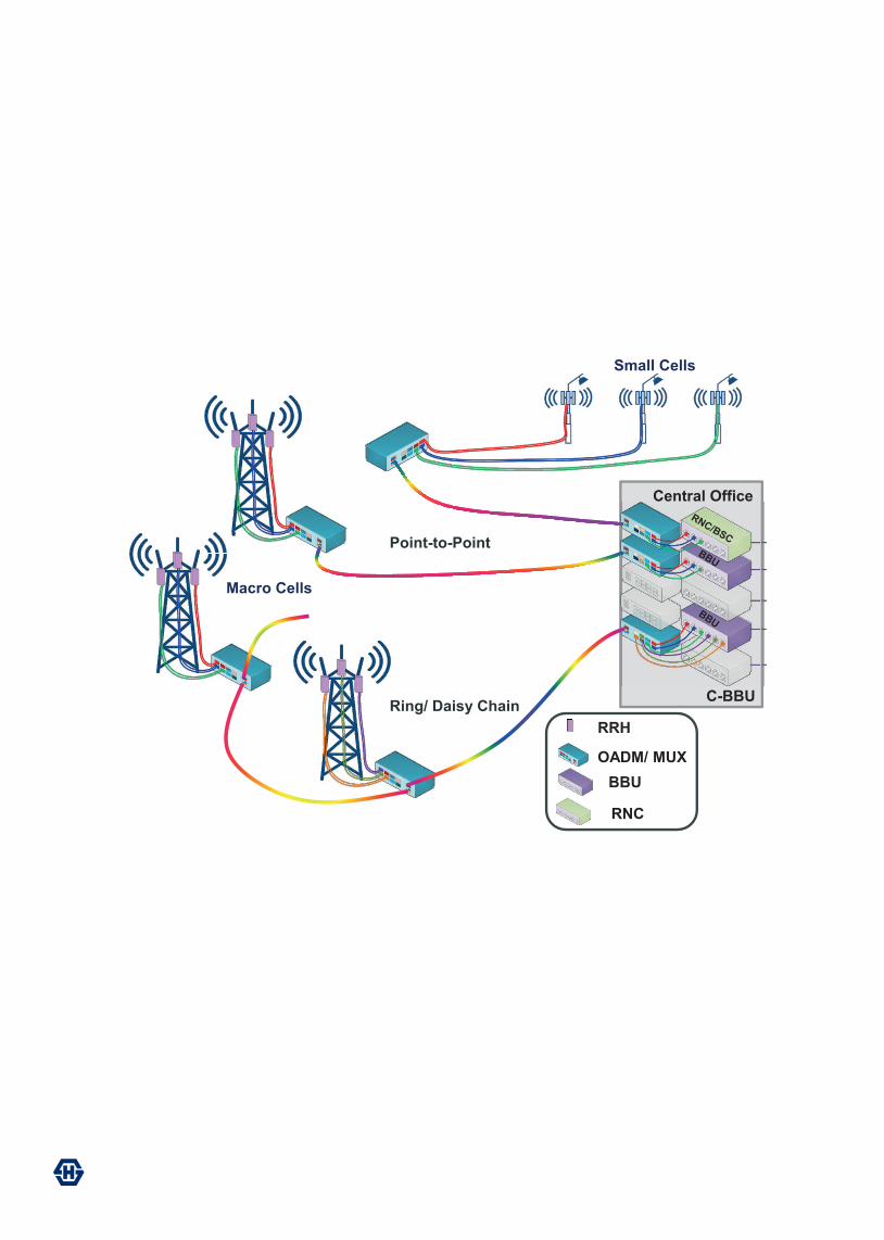
Ring/ Daisy Chain
Point-to-Point
Small Cells
Macro Cells
Central Office
RRH
OADM/ MUX BBU
C-BBU
RNC
D-5143_Rev. A 3
Backhaul and FronthaulTechnologies
Introduction
A recent Cisco VNI Global Mobile Data Traffic Forecast reported that in the next five years there will be 4 billion more mobile-ready devices and connections and the average mobile connection speed will increase 2.4 fold [1].
The Citrix mobile consumer survey in 2014 revealed that 54% of mobile subscribers would abandon a slow-loading page in less than 10 seconds. Furthermore, 63% of millennials were more likely to blame the mobile network for mobile video stalling [2].
With the advent of smart devices, cloud services, newer technologies for fixed and wireless connectivity and very impatient consumers, there is tremendous pressure to strengthen the access and mobile backhaul segment of the network. The copper and microwave connections to the towers can no longer endure the exploding capacity requirements. Fiber is fast becoming the de-facto solution to meet these demands [3].
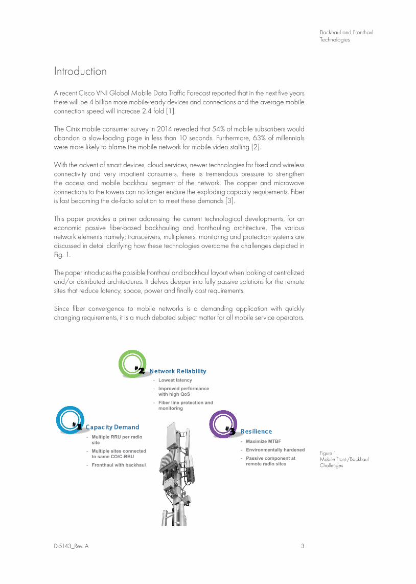
This paper provides a primer addressing the current technological developments, for an economic passive fiber-based backhauling and fronthauling architecture. The various network elements namely; transceivers, multiplexers, monitoring and protection systems are discussed in detail clarifying how these technologies overcome the challenges depicted in Fig. 1.
The paper introduces the possible fronthaul and backhaul layout when looking at centralized and/or distributed architectures. It delves deeper into fully passive solutions for the remote sites that reduce latency, space, power and finally cost requirements.
Since fiber convergence to mobile networks is a demanding application with quickly changing requirements, it is a much debated subject matter for all mobile service operators.
Figure 1 Mobile Front-/Backhaul Challenges
Fig1
C apa c ity Dema nd
N etwork R eliability
R es ilienc e
- Lowest latency
- Improved performance with high QoS
- Fiber line protection and monitoring
- Multiple RRU per radio site
- Multiple sites connected to same CO/C-BBU
- Fronthaul with backhaul
- Maximize MTBF
- Environmentally hardened
- Passive component at remote radio sites
Centralized Architecture
While fibers are mostly being deployed in the backhaul networks, which interconnects the baseband unit (BBU) to the core network, a novel approach of building flexible mobile networks has been pushed forward since a couple of years where fiber is also used from the base station to the antenna, which is called fronthaul [4].
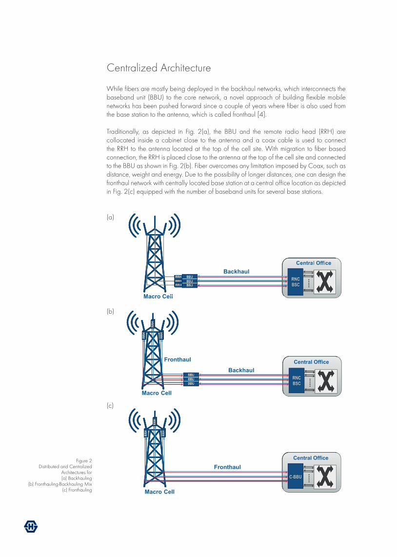
Traditionally, as depicted in Fig. 2(a), the BBU and the remote radio head (RRH) are collocated inside a cabinet close to the antenna and a coax cable is used to connect the RRH to the antenna located at the top of the cell site. With migration to fiber based connection, the RRH is placed close to the antenna at the top of the cell site and connected to the BBU as shown in Fig. 2(b). Fiber overcomes any limitation imposed by Coax, such as distance, weight and energy. Due to the possibility of longer distances, one can design the fronthaul network with centrally located base station at a central office location as depicted in Fig. 2(c) equipped with the number of baseband units for several base stations.
(a)
(b)
(c)
Fig 2 Central Office
Macro Cell
Central Office
Macro Cell
Central Office
Macro Cell
Backhaul
Backhaul
Fronthaul
Fig 2 Central Office
Macro Cell
Central Office
Macro Cell
Central Office
Macro Cell
Backhaul
Backhaul
Fronthaul
Fig 2
Central Office Fronthaul
Macro Cell
Figure 2 Distributed and Centralized
Architectures for (a) Backhauling
(b) Fronthauling-Backhauling Mix(c) Fronthauling
D-5143_Rev. A 5
Backhaul and FronthaulTechnologies
The architecture with the stacked BBUs at the central office or hostel to form a centralized BBU (C-BBU) is referred to as centralized architecture. This architecture aids in easy maintenance at the single location and provides improved security (no cabinets to break into) and reduces energy utilization. Furthermore, in LTE networks, the collocation of BBUs simplifies the X2 interface and also makes the associated latency and synchronization issues insignificant. The X2 interface provisions information exchange between BBUs for smooth handover and coordination.
While the connection between each RRH and BBU can be deployed with a dedicated fiber, the most efficient way would be via the deployment of wavelength multiplexing over a single fiber. An active wavelength division multiplexing (WDM) solution in fronthaul would have stringent signal synchronization requirements. Additionally, space and power limitation would dominate the design of the active system based network.
Passive WDM on the other hand provides low latency solution where colored transceivers are directly deployed in the RRH to provide the necessary WDM wavelength signal.
Network Offloading via Small-Cells and DAS
Once the mobile service provider (MSP) wants to deepen coverage and improve capacity in a targeted area, network offloading via distributed antennas systems (DAS) and small cells is recently gaining popularity as the alternative architecture to macro site expansion. DAS solution is also important where macro coverage is inferior.
A DAS network has a spatially separated antennas connected individually via fibers to the basestation or central office where the baseband processing occurs. The advantage of a DAS system is that it can be shared by multiple operators. Each of the operators then connect their own basestations to the shared distribution system [5]. A DAS can be implemented both indoors (iDAS) and outdoors (oDAS).
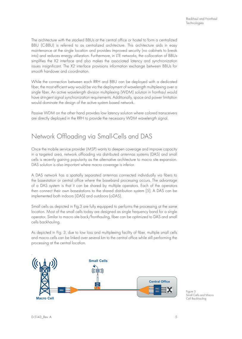
Small cells as depicted in Fig.3 are fully equipped to performs the processing at the same location. Most of the small cells today are designed as single frequency band for a single operator. Similar to macro site back/fronthauling, fiber can be optimized to DAS and small cells backhauling.
As depicted in Fig. 3, due to low loss and multiplexing facility of fiber, multiple small cells and macro cells can be linked over several km to the central office while still performing the processing at the central location.
.
Figure 3Small Cells and Macro Cell Backhauling
Fig 3
Central Office
Macro Cell
Small Cells
The fiber-based access technology has matured over years with passive optical network (PON) fiber-to-the-home applications. Though the penetration of fiber to wireless backhaul or fronthaul network is very recent, the technological maturity is well proven. One must however note that the optical elements as discussed in the following sections need to fulfill certain conditions specific to wireless environment to make the fiber-based wireless network resilient and future-proof.
Different Flavors of Transceivers
Transceivers are the key components of any network. Today grey optics at either 850nm or 1310nm with data rates up to 10Gb/s are mostly deployed on a simple point-to-point fronthaul fiber network and the MSP or carriers are increasing capacity per cell site by stacking more antennas [6]. Each of the antennas with its RRH then requires a dedicated fiber for fronthaul connection. Additionally, multiple of these sites with numerous RRH are connected to the C-BBU at the central office. Thus bandwidth demand is currently satisfied by addition of more fiber strands.
As mobile operators upgrade their networks to 4G LTE with supplementary small cells and DAS, fronthaul will be ubiquitous and installing new fiber will be deemed too expensive. Once the fiber reaches a cell site, the capacity can be simply increased by implementing colored transceivers and multiplexing technology. For passive front/ backhauling, a colored transceiver is directly connected to the RRH with fitting transceiver at the C-BBU using the common public radio interface (CPRI) or open base station architecture initiative (OBSAI) protocol.
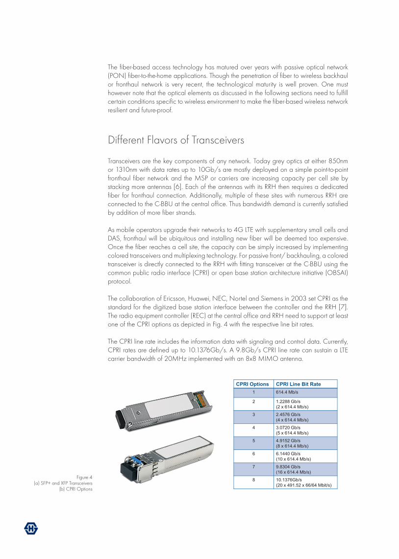
The collaboration of Ericsson, Huawei, NEC, Nortel and Siemens in 2003 set CPRI as the standard for the digitized base station interface between the controller and the RRH [7]. The radio equipment controller (REC) at the central office and RRH need to support at least one of the CPRI options as depicted in Fig. 4 with the respective line bit rates.
The CPRI line rate includes the information data with signaling and control data. Currently, CPRI rates are defined up to 10.1376Gb/s. A 9.8Gb/s CPRI line rate can sustain a LTE carrier bandwidth of 20MHz implemented with an 8x8 MIMO antenna.
Figure 4 (a) SFP+ and XFP Transceivers
(b) CPRI Options
Fig 4
CPRI Options CPRI Line Bit Rate 1 614.4 Mb/s
2 1.2288 Gb/s (2 x 614.4 Mb/s)
3 2.4576 Gb/s (4 x 614.4 Mb/s)
4 3.0720 Gb/s (5 x 614.4 Mb/s)
5 4.9152 Gb/s (8 x 614.4 Mb/s)
6 6.1440 Gb/s (10 x 614.4 Mb/s)
7 9.8304 Gb/s (16 x 614.4 Mb/s)
8 10.1376Gb/s (20 x 491.52 x 66/64 Mbit/s)
D-5143_Rev. A 7
Backhaul and FronthaulTechnologies
OBSAI came out of the collaboration between Hyundai, LGE, Nokia, Siemens, and ZTE in 2002. Similar to CPRI, OBSAI rates range from 728 Mbps to 6.8 Gb/s. Currently, CPRI has a higher market penetration than OBSAI. The link length between BBU and RRU with CPRI can be several tens of km. In densely populated areas or locations where wireless internet services are inferior, offloading of small cells and DAS can be designed by positioning additional colored transceiver with Ethernet protocol at the cell and colocation site. Ethernet speeds range from GbE up to 100Gb/s.
The transceivers at the remote sites however need to be robust and resilient to withstand extreme environmental conditions, as these locations will not all be environmentally hardened. Currently, all 2.45Gb/s coarse WDM (CWDM) wavelengths and eight 9.83Gb/s CWDM red lambda (1470nm-1610nm) CPRI transceivers are available for harsh environments with operating temperature ranging from -40 to +85°C. While designing a front/backhauling network, it is important to investigate the available form-factors, wavelengths, power budgets and most importantly if designing a passive network, the temperature range where the transceivers functions properly.
WDM for Higher Capacity
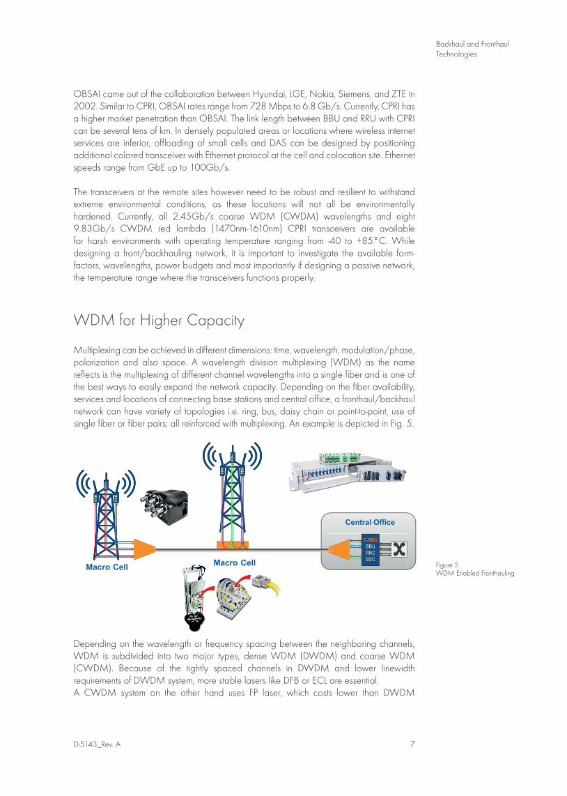
Multiplexing can be achieved in different dimensions: time, wavelength, modulation/phase, polarization and also space. A wavelength division multiplexing (WDM) as the name reflects is the multiplexing of different channel wavelengths into a single fiber and is one of the best ways to easily expand the network capacity. Depending on the fiber availability, services and locations of connecting base stations and central office, a fronthaul/backhaul network can have variety of topologies i.e. ring, bus, daisy chain or point-to-point, use of single fiber or fiber pairs; all reinforced with multiplexing. An example is depicted in Fig. 5.
Depending on the wavelength or frequency spacing between the neighboring channels, WDM is subdivided into two major types, dense WDM (DWDM) and coarse WDM (CWDM). Because of the tightly spaced channels in DWDM and lower linewidth requirements of DWDM system, more stable lasers like DFB or ECL are essential. A CWDM system on the other hand uses FP laser, which costs lower than DWDM
Figure 5 WDM Enabled Fronthauling
Fig5
Central Office
Macro Cell Macro Cell
counterparts. The transmit laser might often be used with a temperature controller, to assure that the central wavelength of the laser does not drift far from the operational bandwidth. The choice of CWDM or DWDM during the network design depends mainly on distance, number of channels and data rate required. Additionally, add/drop multiplexers make them flexible with respect to locations. SK Telecom in South Korean was one of the first operators to use WDM in fronthaul networks.
CWDM provides up to 16 channels while DWDM can carry 80 wavelengths (in C band), that can be extended to 80 more channels when considering the L band. With WDM technology, the capacity increase is limitless. However as cost plays a vital role in deployments, low cost DWDM technology with outdoor-hardened specification is still in research. CWDM based fronthauling is much more economically beneficial and as CWDM transceivers withstand the extreme conditions, are therefore today used in most of the new fronthaul installations.
Passive WDM is also gaining interest as it requires no power and management at the remote sites and thus does not generate extra OPEX. WDM can be built in extremely compact and robust housings as shown in Fig. 5 and is outside plant (OSP) compliant.
Protecting Front/Backhaul Network
Since the revenue per bit for mobile data service is very low, it is imperative to deploy a solution that is cost effective in both CAPEX and OPEX and that also represents a future proof technology for seamless communication. While cost can be an important deciding factor, optical fiber line protection for small cell to macro cell deployments also needs to be resilient to support harsh environmental conditions and any electrical power outages [8].
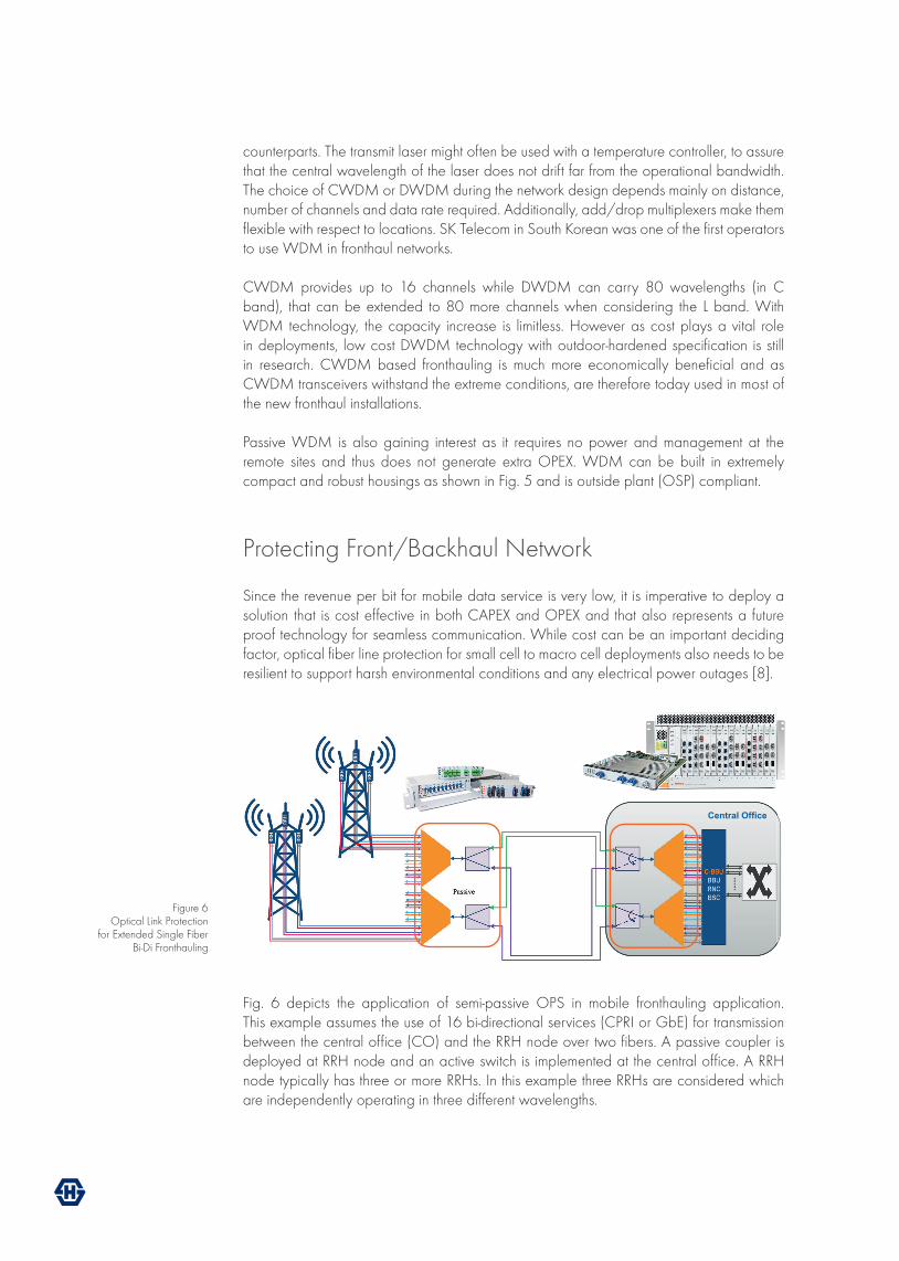
Fig. 6 depicts the application of semi-passive OPS in mobile fronthauling application. This example assumes the use of 16 bi-directional services (CPRI or GbE) for transmission between the central office (CO) and the RRH node over two fibers. A passive coupler is deployed at RRH node and an active switch is implemented at the central office. A RRH node typically has three or more RRHs. In this example three RRHs are considered which are independently operating in three different wavelengths.
Fig6
Central Office
Figure 6 Optical Link Protection
for Extended Single Fiber Bi-Di Fronthauling
D-5143_Rev. A 9
Backhaul and FronthaulTechnologies
The appropriate wavelength is achieved by inserting the corresponding transceiver at the RRH. With the aid of a multiplexer the three different wavelengths in three fibers are combined into a single fiber. The 3-dB coupler after the multiplexer splits the WDM signal into two working and backup line. At the central office, the active switch detects the signal in the working like and switches to the backup line when fault occurs.
Because of the use of purely passive coupler at the RRH end, with such a semi-passive OPS architecture, no power supply is required at the remote node thus minimizing the operational cost and making the design resilient to electrical power outages. There is also a possibility of passive remote monitoring and management via the implementation of a reflector at the RRH node when desired. This design is appropriate for harsh environment and extended temperature ranges and can support WDM or Optical Add/Drop (OADM) integration for point-to-point and ring topologies. The BBU unit at the central office has network management access to the switch to monitor and user defined threshold values.
Passive Monitoring for Front-/Backhauling
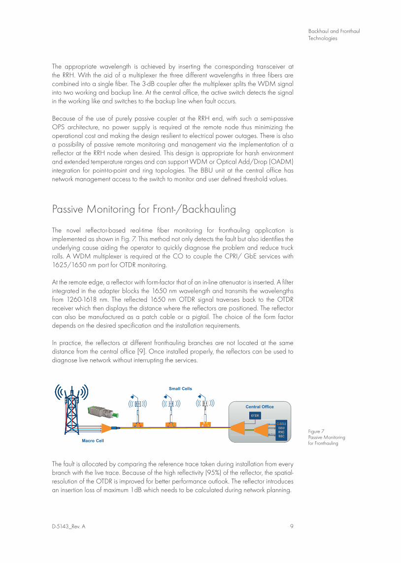
The novel reflector-based real-time fiber monitoring for fronthauling application is implemented as shown in Fig. 7. This method not only detects the fault but also identifies the underlying cause aiding the operator to quickly diagnose the problem and reduce truck rolls. A WDM multiplexer is required at the CO to couple the CPRI/ GbE services with 1625/1650 nm port for OTDR monitoring.
At the remote edge, a reflector with form-factor that of an in-line attenuator is inserted. A filter integrated in the adapter blocks the 1650 nm wavelength and transmits the wavelengths from 1260-1618 nm. The reflected 1650 nm OTDR signal traverses back to the OTDR receiver which then displays the distance where the reflectors are positioned. The reflector can also be manufactured as a patch cable or a pigtail. The choice of the form factor depends on the desired specification and the installation requirements.
In practice, the reflectors at different fronthauling branches are not located at the same distance from the central office [9]. Once installed properly, the reflectors can be used to diagnose live network without interrupting the services.
The fault is allocated by comparing the reference trace taken during installation from every branch with the live trace. Because of the high reflectivity (95%) of the reflector, the spatial-resolution of the OTDR is improved for better performance outlook. The reflector introduces an insertion loss of maximum 1dB which needs to be calculated during network planning.
Figure 7 Passive Monitoring for Fronthauling
Fig7
Macro Cell
Small Cells
Central Office
The Passive Advantage
With fast increasing mobile fronthaul/ backhaul deployments, it is important to select the technology that promises a good return on investment. Spectrally efficient passive mobile fronthauling and backhauling with the use of WDM wavelengths enjoys the following advantages:
• Increase in capacity per cell site with simple plug-and-play modules.• Economic advantage with lower CAPEX (< 50% compared to active) and lower OPEX
(support/maintenance, site rental and energy conservation).• Lower latency improving the maximum allowable distance.• Requires fewer resources w.r.t. space, energy, cooling with centrally located BBU.• Robust and resilient for outside plant application.• Complete transparency to carrier services, i.e., independent of transport, migration and
simple to long term changes.
Conclusion
In tomorrow’s online and interconnected world, we will see an unprecedented growth in data traffic requiring deployment of novel front/backhaul technologies with improved performance in harsh environments and with lower power consumption and lower cost.
Addressing these requirements, this paper sheds light on different temperature hardened colored transceivers, multiplexers in different form factors together with protection planning and monitoring that are an integral part of network design and planning while expanding wireless capacity and coverage. There is no single easy solution to every upgrade, but tackling the technical and business challenges step-by-step makes the back- and fronthaul evolution more simple and efficient.
About the Author
Susmita Adhikari has a M.Sc. in Digital Communication with over six years of research and product management experience from long-haul communication to metro. At HUBER+SUHNER Cube Optics, she works as a Product Placement Manager and ensures a good visibility of newly introduced products and network solutions via technical marketing and customer interactions.
D-5143_Rev. A 11
Backhaul and FronthaulTechnologies
Acronym
BBU base band unit C-BBU centralized BBU CAPEX capital expenditure CPRI common public radio interface CWDM coarse wavelength division multiplexing DAS distributed antenna system DWDM dense wavelength division multiplexing LTE long term evolution MSP mobile service provider OBSAI open base station architecture initiative PON passive optical network OPEX operational expenditure OSP outside plant OTDR optical time domain reflectometry RE radio equipment REC radio equipment controller RRH/U remote radio head/unit
References
[1] Cisco, “Cisco VNI Global Mobile Data Traffic Forecast, 2014 - 2019,” http://www.cisco.com/c/en/us/solutions/service-provider/visual-networking-index-vni/index.html~vniforecast 2015.
[2] Citrix, “Mobile Consumer Survey,” https://www.citrix.com/content/dam/citrix/en_us/documents/oth/citrix-mobile-consumer-survey.pdf 2014.
[3] P. McClusky and J. Schroeder, “Fiber-to-the-antenna: Benefits and protection requirements,” in Telecommunications Energy Conference (INTELEC), 2012 IEEE 34th International, pp.1-6, http://ieeexplore.ieee.org/stamp/stamp.jsp?tp=&arnumber=6374502&isnumber=6374450, Sept. 30 2012-Oct. 4 2012.
[4] “Seamless Communiation with Passive Optical Mobile Front and Backhauling”, HUBER+SUHNER Cube Optics, White Paper, D-5129, 2014.
[5] http://www.thinksmallcell.com/[6] P. Rigby, “Mobile fronthaul: a new optical opportunity”, Fibre Systems. Issue 6, Winter
2015.[7] http://www.cpri.info/[8] “Resilient Semi-Passive Optical Link Failure Protection”, HUBER+SUHNER Cube Optics,
White Paper, D-5129, 2015.[9] “Real-Time Monitoring of Passive Optical Networks”, HUBER+SUHNER Cube Optics,
White Paper, D-5134, 2015.

HUBER+SUHNER Cube Optics AGRobert-Koch-Strasse 3055129 MainzGermany
phone: +49-6131-69851-0 fax: +49-6131-69851-79 [email protected]
www.hubersuhner.comwww.cubeoptics.com
HUBER+SUHNER Cube Optics AG is certified according to ISO 9001.
WAIVERIt is exclusively in written agreements that we provide our customers with warrants and representations as to the technical specifications and/or the fitness for any particular purpose. The facts and figures contained herein are carefully compiled to the best of our knowledge, but they are intended for general informational purposes only.
D-5143 Rev. A