white phosphor nvg’s: how the army is “making owning the
TRANSCRIPT

White Phosphor NVG’s: How the Army is “Making Owning the Night” safer
The U.S. Army is arguably the greatest night fighting formation in history. On any given night, the Army has unquestionably more aircraft in-flight using night vision technology, flying more varied mission profiles than any other nation in the world. For generations of Army aviators and crew members, the night vision system of choice has been the AN/AVS-6 Aviator’s Night Vision Imaging System (ANVIS) green phosphorus night vision goggles. First introduced in 1985, ANVIS goggles have been used in every Army airframe around the world conducting training and combat operations. They enable the Army to own the night. But like all things, time and technology has caught up and passed the tried and true ANVIS.
Night OperationsAs the Army looks to refocus from nearly two
decades of counterinsurgency (COIN) operational threats to the more lethal threats found in executing multi-domain operations (MDO) and large-scale combat operations (LSCO), Army aviation flight profiles are adjusting to pre 9/11 low-level flight to counter emerging peer/near-peer integrated air defense systems (IADS). The threat presented by an IADS or when facing an anti-access/ area denied (A2AD) scenario, requires today’s aircrews to operate at lower altitudes, from increased ranges, and while under the cover of darkness. Aviation crews must execute their mission within a high threat system environment which the enemy has had decades to prepare for.
Age of current NVGThe current ANVIS uses the same Type 7 image
intensifier tube (IIT) introduced in 2002. When the 2002 fielding was complete, the Army issued over 16,902 Type 7 IIT to the force.
Having been initially installed nearly 20 years ago, the current ANVIS Type 7 IIT is beginning to reach its economic useful life (EUL) of 20 years. As the
tubes reach the EUL in FY22, units will begin to see an increase in NVG failure rates, decreases in overall tube performance, until finally, the tubes need replacement.
With the Type 7 IIT reaching their EUL, it presents an opportunity for units to replace their aging tubes with the high figure-of-merit (HFOM) white phosphorous Type 8 IIT.
Night vision goggle 101; what is a “Figure-Of-Merit” (FOM)?
The FOM of a night vision sensor is simply the product of its Signal to Noise Ratio (SNR) times its Resolution inline pair/mm (lp/mm). (FOM=SNR x Resolution) The higher the line pairs, the greater the visual acuity. The improvements in the microchannel plate (MCP) are how the HFOM IIT increases the line pairs and gives the user better visual acuity. Figure 1 below shows the resolution of a high modulation transfer function (MTF), or how well the IIT images every spatial frequency.
What is the interim solution?The Type 8 White Phosphor High Figure of Merit
(WP HFOM IIT) ANVIS:
• Visibly identical to the existing Type 7 IIT, the Type 8 WP HFOM IIT will require no additional training to install or operate. They are for all intent and purposes, functionally the same as the current IIT. With the improved MCP, the Type 8 HFOM WP IIT brings not only a new color
Figure 1. Relative resolution of image intensifier tubes. (Property of C5ISR)

2
phosphorous but other improvements.
• Type 8 HFOM IIT surpasses the figure of merit of the current IIT, 1800, with a figure of merit between 2300 and 2400. Although the visual acuity is about the same (20/25), it will mean better depth perception and improved contrast. The WP HFOM IIT offers better low-light level performance, particularly in low moon angle or no moon/ starlight only nights. Again, bringing a level of risk reduction that commanders can leverage for mission completion and aircrew safety.
• According to an Air Force Research Lab study conducted in 2017, the HFOM IIT provided approximately 30 percent greater photocathode sensitivity then legacy IIT (ACC Project 18-240R), other noticeable improvements are the decreased halo effect, approximately 0.65mm compared to the legacy .85mm requirement and increased SNR of 33 lp/mm from 28 lp/mm. Figure 2 below shows the difference in visual clarity in low light conditions between a current FOM IIT and HFOM IIT. Figure 3 below shows the reduced halo and resolution during high illumination as seen in a current FOM IIT versus a HFOM white phosphor IIT.
HD Tube characteristicsCurrent ANVIS systems use P43 green phosphor,
which phased out the P22 green phosphor used in older systems, and the HFOM IIT uses P45 white phosphor. Figure 4 below contrasts the spectral intensities of the white and green phosphors. Notice that the white phosphor (P45) nearly mirrors the green phosphor (P43), with the addition of the blue (400-450 nm) content. Figure 5 below shows the smaller halo size of the HFOM IIT and contrasts the white phosphor (P45) with the green phosphor (P43).
What is the near-term timeline?Before you rush to your nearest
goggle maintainer and pester them about getting the new IIT tubes, there are still a few kinks to work out. Namely, the tubes will require a qualification process through the Army. At the time of writing, the only HFOM tubes currently used by the Army are commercial off the shelf (COTS). According to Mr. Ronald Boisvert, Assistant Program Manager for ANVIS, Product Manager (PM) Soldier Maneuver Sensors, the testing to qualify the HFOM IIT is underway.
However, to support this effort, U.S. Army Colonel Ryan Coyle, the director for Training and Doctrine Command (TRADOC) Capability Manager for Aviation Brigades (TCM-AB), signed
Figure 2. Relative photocathode intensities of the current FOM (left) and HFOM (R) IIT green phosphor in low illumination conditions. (Photos courtesy of C5ISR)
Figure 3. Relative HFOM photocathode intensities of the white and green phosphors in high illumination conditions. (Photos courtesy of L3 Technologies)
Figure 4. Relative spectral intensities of the white and green phosphors. (TM 2017-12)

3
the authorization in January 2019, beginning the process of replacing the older IIT with HFOM IIT. Once the COTS IIT is qualified, the industry will begin producing tubes to meet the new standards. The two manufacturers can each produce approximately 2,300 HFOM IIT monthly.
Test/EvaluationsSeveral organizations have conducted evaluations
of the HFOM IIT, including the Army and Air Force Research Labs, the US Army Aeromedical Research Lab (USAARL), and the 160th Special Operations Aviation Regiment (SOAR). These have included bench tests and user-flight evaluations. While the bench tests did show a marked improvement of the HFOM Type 8 IIT over the legacy Type 6 and 7 IIT when compared, there was a nominal difference between the P45 white and P43 green phosphor tubes. Surprisingly, there was an overwhelming user preference for the P45 white tubes.
According to the USAARL study, “although the laboratory measurements did not find any significant differences between the two matching white and green phosphor ANVIS for resolutions, gain, halo sizes, automatic brightness control (ABC) responses, smear, etc., the flight assessments showed almost a unanimous preference for the white phosphor ANVIS. This suggests there are other factors considered by the flight evaluators that are not measurable or evaluated in the laboratory.” (USAARL Technical Memorandum (TM) 2017-12)
Currently, USAACE flight crews are operating under an interim airworthiness release (AWR) for testing, the last being issued by Aviation Engineering
Directorate (AED) for the CH-47 this past September. The interim AWR will be rescinded once the HFOM IIT is qualified. AED will include the HFOM IIT as part of the existing ANVIS AWR.
Supply/ ProductionAccording to the PM, the revised aviation
maintenance action message (AMAM) has been released and the HFOM tubes can be ordered through the PM, using Class IX Air unit funds. The Headquarters Department of the Army (HQDA) memo is in the final draft and is staffed, pending its release in the coming weeks.
Fielding PlanThe plan to get the new tubes into the combat
aviation brigades (CAB) is through attrition. Once a Type 7 IIT goes bad, it can be replaced with a Type 8 IIT. A CAB, using its Class 9 ground funding, can expect to pay roughly $2,600.00 for an improved HROM IIT. This means it will cost nearly $1.9 million to replace every IIT in a CAB. The ability to upgrade the ANVIS is already resident within the CAB’s aviation support battalion.
What is the future of night vision?The battlefield envisioned during MDO and
LSCO will be more complex than any currently encountered. Lower altitudes will drive a need for more “heads up and eyes out” systems. To meet this need, the industry is developing two systems; the enhanced night vision goggle binocular (ENVGB) and the integrated visual augmentation system (IVAS). These systems are projected to have integrated displays (e.g., think an integrated head-
Figure 5. Halo sizes of high FOM ANVIS on the green (left) and white (right) phosphor channels. (TM 2017-12)

4
https://breakingdefense.com/2020/01/v-280-tiltrotor-can-fly-unmanned-bell-says/
up display (HUD)) designed to increase situational awareness (SA) and get crews’ heads up and eyes out of the cockpit.
The estimated weight of the system is less than the current ANVIS, making them less taxing on flight crews. There are also plans to include an augmented reality capability to the IVAS that will provide synthetic terrain and flight cues to aid in flight under degraded visual environments. For crew chiefs and door gunners, these systems could provide target information or system status, giving them greater SA on the status of the mission and their aircraft.
ConclusionArmy aviation will continue to conduct aviation
operations during periods of darkness everywhere helicopters operate. They will be part of the force used to penetrate the enemy’s IADS and regain access to the areas denied during MDO. In order to continue to do this, aircrews require an updated night vision capability. That capability will be delivered by the white phosphorus high figure of merit image intensifier tubes being incorporated in today’s ANVIS night vision systems.
References ACC Project 18-240R, High Figure of Merit White and Green Phosphor Night Vision Goggle Update Force Development Evaluation, May 2018, Air National Guard Air Force Reserve Command Test Center, Tucson AZ
Rubinstein, J, Chambers, S, Stachowiak, C, Fedele, P, Starvis, K, Merritt, J, A Human-Performance Comparison of Green-Phosphor and White-Phosphor Night-Vision Goggles, Aug 2017, US Army Research Laboratory, Aberdeen Proving Ground, MD
MFR, Recommendation for Modification AN/AVS-6, Aviator’s Night Vision Imaging System (ANVIS) with White Phosphor Intensifiers, 4 Jan 2019, USAACE, Ft. Rucker AL
MFR, High FOM Green and White ANVIS Limited Laboratory and Flight Results, USAARL Technical Memorandum 2017-12, US Army Research Laboratory, 6 June 2017, Ft. Rucker, AL
Joseph W. SanteeCW5, AVFVL-CFT Survivability Tech AdvisorAMSO/ UH-60 SP/IERedstone Arsenal, AL

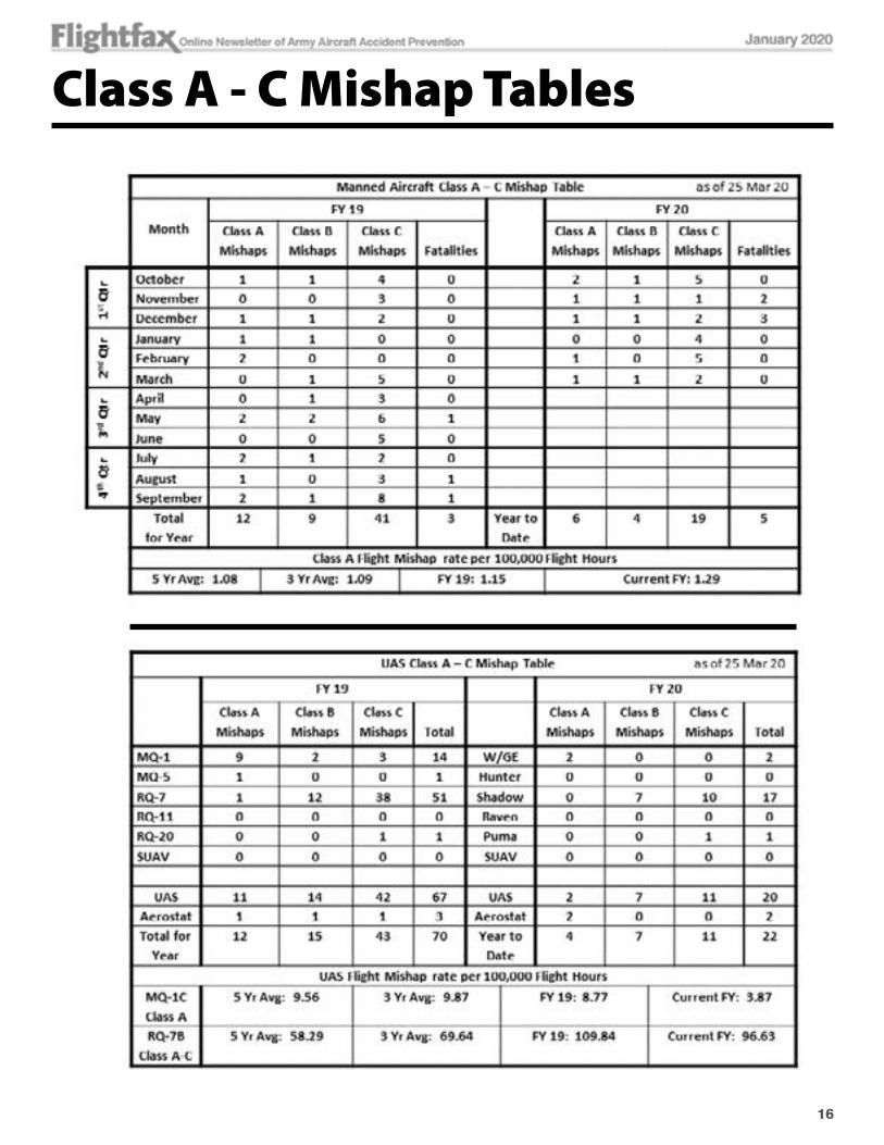
Manned Aircraft: Army aviation experienced 12 Class A, eight Class B and 44 Class C aircraft mishaps in FY19, a decrease of 31 percent from the 11 Class A, nine Class B and 73 Class C (total 93) reported in FY18. The manned Class A flight mishap rate (rotary wing + fixed wing) for FY19 was 1.15 (Class A flight mishaps per 100,000 hours of flight time), similar to the 1.19 rate recorded in FY18. The five-year rate stands at 1.10.
The Class A through C flight mishap rate for FY19 was 5.63, a 34 percent decrease from the 8.59 rate for FY18. This was primarily due to a 38 percent reduction in Class C mishaps reported in FY19. Additionally, there was a decrease in total fatalities from 6 in FY18 to 3 in FY19.
Class A Mishaps: There were 12 (10 flight, 2 flight-related) Class A mishaps, eight of which occurred at night. Three mishaps were forward deployed. Three mishaps were associated with degraded visual conditions (DVE). Three of the mishaps resulted in three fatalities (two U.S., one foreign).
Human error remains the leading causal factor in mishaps generally contributing to approximately 80 percent of all Army aviation accidents. For FY19, nine (75 percent) of the Class A mishaps had human error as a cause factor with three (25 percent) reported as materiel failure. Crew coordination factors were noted in nine of the Class A mishaps.
Three Class A materiel failure mishaps were recorded. One H-64 sprag clutch failure, one engine failure, and one H-47 fire during ground taxi. No fatalities were associated with these mishaps.
Class B Mishaps: Eight Class B incidents were reported, six flight, one flight-related and one aircraft ground. Six had a human error cause factor, one materiel failure and one environmental. A total of three mishaps occurred at night and three forward-
deployed. The Class B flight mishap rate was 0.69 Class B flight mishaps per 100,000 hours.
Class C mishaps: Forty-four (34 flight, nine ground, one flight-related) Class C mishaps were reported with 14 occurring at night. Cause factors included 28 human error, seven materiel failures, six environmental (one bird, wind, hail, storm damage, and two lightning), and three unknown or not yet reported. The Class C flight mishap rate was 3.91 Class C flight mishaps per 100,000 hours.
2019 breakdown by aircraft type:Synopsis of selected FY19 mishaps follows:
(*denotes night mission)
Manned Class A- H-64D: Aircraft crashed in rough terrain during rotational training. Aircraft drifted rearward into rising terrain. Both crewmembers exited the aircraft with minor injuries.
* H-64E: Aircraft suffered a dual sprag clutch failure in the main transmission at a hover resulting in a hard landing.
* H-72A: During night vision goggle (NVG) training aircraft drifted rearward. Tail rotor struck a tree.
- EO-5C: Aircraft landed gear up during practice emergency procedure training.
- Other RW: Aircraft descended into trees following an engine failure.
* H-60M: During NVG infiltration training to an elevated structure, the soldier exited the aircraft and fell 30 feet resulting in fatal injuries.
FY2019 Mishap Review
Class 2018 2019A 11 12
B 9 8
C 73 44
Total 93 64
Fatalities 6 3
5
Type Aircraft
Class A Class B Class C
H-60 3 4 18
H-64 4 1 8
H-47 2 1 4
H-72 1 0 5
Other RW 1 1 0
Fixed Wing 1 1 9

* H-47: Aircraft crashed during infiltration with brown-out conditions.
* H-64E: Aircraft landed hard under brown-out conditions to a field site. Damage to main and tail rotor system, target acquisition designator system (TADS)/pilot night vision system (PNVS) sights, and fuselage.
- H-47: During ground taxi, a hole in the hydraulic line caused misting fluid to catch fire from wire bundle chaffing.
* H-60M: During go around on NVG mission, one Soldier exited the aircraft while it was still airborne. One fatality.
* H-64D: While flying nap of earth (NOE), aircraft struck a large set of power lines. Aircraft landed hard with damage.
* H-60L: Aircraft crashed following the failure of the No. 1 engine at low airspeed and altitude; one fatality.
Unmanned aerial systems (UAS): There were 71 Class A through C mishaps
reported in FY19, an increase of 61 percent over the 44 in FY18. There were 12 Class A mishaps reported in FY19 compared to seven in FY18.
RQ-7B Shadow. A significant rise (92 percent) in mishaps occurred in the RQ-7B Shadow with a total of 52 Class A-C mishaps in FY19 compared to 27 reported the previous year. This reflected in the RQ-7B Class A-C flight mishap rate increasing from 43.34 mishaps per 100,000 hours in FY18 to a rate of 108.67 in FY19. Materiel failure accounted for over 60 percent of the cause factors in Shadow mishaps with human error manifesting in approximately 30 percent. The five-year rate is 58.29 for the RQ-7B.
MQ-1C Gray Eagle. For the MQ-1C Gray Eagle, the numbers increased from three Class A mishaps in FY18 to eight in FY19 resulting in a Class A flight mishap rate of 8.77 (Class A flight mishaps per 100,000 flight hours). The FY18 rate was 3.52.
The five-year Class A rate is 8.94. In FY19 human error accounted for approximately 60 percent of the Gray Eagle mishaps with 31 percent materiel failures. Failure to follow the checklist or designated procedures were prominent in human factors incidents.
2019 breakdown by aircraft type:
Synopsis of selected accidents (FY19):
UAS Class A- MQ-1C: Landing gear collapsed on touchdown. The gear was not in the fully extended position.
- MQ-1C: After takeoff, the aircraft was unable to sustain a climb to clear terrain. The aircraft was unable to take off and climb normally because of frost on the aircraft, which reduced lift and increased drag.
- MQ-1C: Aircraft crashed following a drop in fuel pressure then engine failure.
- MQ-5B: Aircraft crashed following dual-engine RPM anomaly and loss of altitude.
- RQ-7B: Landing aircraft struck a stationary aircraft parked on the runway. Lack of communication between co-located units.
- MQ-1C: Operating weight incorrectly entered instead of the actual weight. The autopilot provided inputs that caused the aircraft to crash.
- MQ-1C: Operating weight incorrectly entered (2,728 pounds) into the VSM preset window instead of the actual ramp weight (3,515 pounds). When the flight mode of the aircraft changed from takeoff to climb the autopilot forced a nose-down attitude causing the aircraft to impact the terrain.
Class 2018 2019
A 7 12
B 11 16
C 26 43
Total 44 71
6
Type Aircraft
Class A Class B Class C
MQ-1 9 2 3
MQ-5B 1 0 0
RQ-7B 1 13 38
RQ-20 0 0 1
Aerostat 1 1 1
Total 12 16 43

- MQ-1C: Crew experienced a loss of line of sight with UAS during the final approach and reported attempts for alternate ground and satellite terminal linkage were unsuccessful. Aircraft was recovered following crash landing with damage.
- MQ-1C: Crew experienced decreasing oil pressure followed by engine failure.
- MQ-1C: Aerial Vehicle (AV) suffered a No.1 alternator failure that led to a lost link.
- MQ-1C: Aircraft sustained damage on takeoff following reported abort by the automatic takeoff and landing system (ATLS). Aircraft departed the runway and came to rest on an adjacent runway.
Other UAS mishaps- RQ-7B: During the mission, the AV experienced a propulsion failure. The parachute was deployed and the AV has been recovered. (Class B)
- RQ-7B: AV experienced a suspected electrical failure resulting in a malfunction of the mission and flight computer systems. Intermittent power interruption to the Airborne Computer Equipment (ACE) box caused the internal system processor to fail and not recover. The AV sustained significant damage. (Class B)
- RQ-7B: Aircraft crashed following reported attitude anomalies and oscillations. The suspected cause of the mishap was foreign object debris (FOD) in the pitot tube line causing an imbalance of pressure inside the pitot-static system. This caused the airspeed to drop and resulted in the AV flight dynamics becoming uncontrollable. (Class B)
- RQ-7B: During recovery, the AV experienced a hard landing and bounced over the arresting pendants and the barrier net. Adverse tail wind occurred just prior to touchdown causing the AV to land 12 feet long with a hard landing. The AV continued to roll impacting a handrail and suffered significant damage. (Class B)
- RQ-20B: Reported lost link during flight. Aircraft was not recovered. (Class C)
Aerostat mishaps- Aerostat: Aerostat experienced a break-away while aloft at 4,100 feet above ground level (AGL) during reported 45-55 knot winds. Forecast winds were reported at 25 knots. (Class A)
- Aerostat: Damage occurred to the aerostat while it was docked for anticipated poor weather which culminated in 70 miles per hour (mph) wind conditions. (Class B)
- Aerostat: While the aerostat was 350-400 feet AGL, the aerostat’s power cord was accidently disconnected causing the aerostat to lose power and deflate. (Class C)
SummaryAs human error continues to remain the primary
cause related to mishaps, aviation leaders and Soldiers must stay keen on attention to detail in conducting their daily duties and aircraft operations. The following unit efforts can assist in driving down mishaps in FY20.
• Maximizing crew coordination during training events leads to better outcomes during missions and especially during mission situations where an emergency or an unforeseen event occurs. Taking the time to implement focused simulator training scenarios that provide aircrews with situations that are unforeseen promulgates in these crews effectively addressing situations in real missions that require maximum crew coordination.
• Rehearsing each mission provides immediate positive results for the proper conduct of the mission, for identifying critical points during the mission where crews must increase their communication, and for reducing confusion.
• Increase emphasis on briefing operations in DVE and brown-out hazards during takeoff and landings. DVE continues to be a Class A mishap producer. Apply training scenarios in a simulator that provides the unexpected for aircrews during brown-out operations.
• Emphasize training your aviators to think while performing emergency procedures. Focus on individual competencies (thinking through the situation) versus procedural (acting without thinking).
• During times of fewer flying hours, it may challenge proficiency versus just currency in individuals and crew training levels. Keep crews focused and maximize training opportunities and simulators.
• Take added precautions when crews are operating away from the parent headquarters.
7

Assist your teams and platoons who are task-organized supporting non-habitual units. Apply more deliberate controls on their operations and authorities for a period of time until the crews become familiar with the unit operating procedures.
Jon DickinsonAviation DivisionDirectorate of Assessments and PreventionUnited States Army Combat Readiness Center
8
Test, Measurement, and Diagnostic Equipment (TMDE)
There I was, a new 67R Apache maintainer tasked with conducting scheduled maintenance that required a few special tools from ground support equipment (GSE)/tool room. With little experience as a maintainer, I don’t know what I don’t know and overlooking the importance of ensuring my special tools have a current inspection sticker can be critical. Luckily my oversight was caught by the technical inspector (TI) when he arrived at the aircraft to ensure my work was completed.
Not only did I use a torque wrench that had exceeded its inspection date, but I also failed to document the serial number of the torque wrench and the torque required on my Department of the Army (DA) Form 2408-13-2 Related Maintenance Actions Record. This brings to light a few flaws in the quality assurance process. The tool room issued a tool outside its inspection window; it was not caught by the custodian nor me at issue. The systems we have in place are there to prevent human error, but it still happens. Discipline
and integrity are critical when maintenance is involved. I was not in a rush to complete the task, only young, not properly trained, supervised or aware of the importance of my role in the risk mitigation process.
The tool room is required to track all tools and those requiring TMDE inspections in accordance with Technical Bulletin (TB) 43-180, Technical

9
Bulletin Calibration and Repair Requirements for the Maintenance of Army Materiel. The tool room custodian tracks these items on a flow chart providing a required calibration/inspection schedule to help manage TMDE and ensure the tool is within calibration. Not all special tools are maintained by the tool room, so individuals need to be aware of what items are on their hand receipt and if it requires calibration and inspection. When a tool is issued out, the custodian should visibly:
• Inspect the TMDE
• Ensure the TMDE is serviceable and within calibration/inspection date
• Ensure recipient is aware the tool is within calibration/inspection date (note date for records)
• TMDE is in its protective case
If there is an issue with the tool, it should be removed from service and sent in for inspection. If at any time the calibrated item is dropped or damaged it should be returned to the tool room and reported to the custodian for repair.
Using the wrong torque wrench, or one not in calibration, can result in improper maintenance being conducted. The sequence of events from a simple nut not being properly torqued will, sooner or later, result in a maintenance issue or worse case, a catastrophic aircraft accident.
Attention to detail, no matter how small it may seem is vital to the entire maintenance process and the safe operation of aircraft and ground equipment. Leaders need to understand that the tool room custodian job is more than just a
sign in and sign out roster person. This seemingly unimportant job, if not managed correctly, can have devastating effects on Army aviation operations. So leaders, check your tool room and the custodian who operates it. Maintaining your TMDE in a serviceable condition is one of the keys to your unit accomplishing its mission.
CW4 Robert MoranAviation Accident InvestigatorAviation DivisionDirectorate of Assessments and PreventionUnited States Army Combat Readiness Center

10
Underwater Location and Recovery Operations of Aircraft Wreckage and Flight Data Recorders
This article provides an overview of the issues peculiar to underwater location and recovery operations of aircraft wreckage and cockpit voice and flight data recorders, as well as the expertise, procedures and, equipment needed to mount an effective response to such an accident. It is intended for use by all who might find it helpful, in the US Army and beyond, and in particular of course by air accident investigation authorities who might at any moment find themselves faced with the task of investigating the loss of an aircraft in these very challenging circumstances.
Lessons Learned and ConsiderationsThe lessons learned provide an
overview of the issues peculiar to underwater location and recovery operations, and the expertise, procedures, and equipment needed to mount an effective response to such an accident.
Any State that has a coastline, internal body of water, or aircraft on its national register flying over waters, may face the responsibility of having to conduct an investigation into the loss of an aircraft in its territorial waters or on the high seas. Fatal accidents with an underwater dimension occur regularly. When an aircraft comes down in water, whether at sea, in a lake or river, the first need - access to the accident site - is problematic in itself. The problems become greater as the water becomes deeper.
Underwater location and recovery has extremely challenging characteristics, and requires a well-planned and timely response, coordinated amongst many parties. Inadequate preparation or poor management of the initial investigative response has the potential to degenerate into a crisis, and can threaten crucial evidence.
Safety investigation authorities will not generally be able to conduct an investigation having an
underwater dimension without outside assistance. Relationships, therefore, need to be established in advance with potential partners and sources of assistance. Within the agencies’ safety investigation authority, these partners should include agencies with responsibilities for matters relating to the sea, the naval service, and the diplomatic service. It is especially important to have a procedure to secure rapid access to bathymetric and bathythermograph data, at least for national waters. Partnership relationships should also be established with colleagues in other safety investigation authorities.
Although advice should be taken from agencies such as the police, the U.S. Navy and Coastguard, overall control of the operation should always be retained by the safety investigation authority. Assistance may usefully be sought from other national investigation authorities who have recent experience of mounting similar operations.
It is also important to have information about where relevant equipment may be sourced. While it might be possible to borrow some equipment from partners, it may be necessary to enter into hire contracts for sea-going vessels, underwater craft, and other specialized or expensive equipment.

11
Contract details for suitable contractors, and an understanding of the kinds of equipment and expertise (for example, in diving) each can offer, should be part of the standing preparations for a possible underwater operation. Check-lists for underwater operations are important for planning purposes. But no two accidents are the same and detailed planning will inevitably be event-specific. Effective equipment and personnel may be expensive but they can reduce overall costs. “Employing an expert is expensive, but not as expensive as employing a non-expert.”
The VesselThe key factor in the selection of the vessel
and its onboard equipment is the nature of the location of the accident site: sea state conditions, probable depth, and the seabed environment. Other important factors will be the proximity of the nearest useful port and the availability of suitable vessels. Safety investigation authorities unused to underwater operations often underestimate the time it can take to get the necessary maritime assets into a position to start work. In considering the suitability of the vessels available, account should be taken of their capability to perform the required task in the time available, including their fitting out with specialized equipment such as acoustic devices for detecting 37.5 kHz signals and, when necessary, with a hull-mounted multibeam sonar for bathymetry of the seabed. Other considerations will be the vessel’s present location and availability, transit time to the accident site, and the entire charter cost, including the provision of equipment, and mobilization/ demobilization. Relatively small craft, for use in
operations on lakes, rivers and close inshore, is unlikely to be difficult to secure. For operations at sea, it is necessary to know where to find the appropriate kind of larger vessel. If no suitable State vessels are available an approach to the chartering market may be necessary, and consideration given to issuing a call for tenders. Ancillary issues may be the need for a helo-deck and any auditing or certification requirements.
Mobilization of large vessels with deep-water recovery capability can take time. There may be an advantage in taking a two-stage approach, first employing a smaller vessel able to reach the location quickly and begin the task of locating the Underwater Locator Beacons (ULBs), pending the arrival of a recovery vessel. The decision to dispatch the recovery vessel should only be made once the wreckage has been located, and the delay between its location and the departure of the vessel should be kept to a minimum. If the wreckage has not been located during the period in which the ULBs can be assumed to be transmitted, it will be necessary to proceed to another phase of location, using sonar equipment, which will normally correspond to different vessel requirements. Once the vessel has been selected and contracted, it is important that a good working relationship is established and maintained between the investigation team and the captain of the vessel.
The depth at which the aircraft wreckage and flight recorders are believed to be located will be the primary determinant of the recovery options. Air diving is feasible at depths up to 131 feet/40 meters and saturation diving up to 1,640 feet/500 meters.
However, for deep water and sustained operations, the use of a Remotely Operated Vehicle (ROV) is generally the best option. These are connected to the parent vessel by an “umbilical” carrying power and navigational and imagery capabilities. They come in many forms and sizes and may be equipped with one or more “manipulators” for working at the accident site. The use of an ROV permits the whole investigation team to view and exploit in real-time the images transmitted from the ROV to the parent vessel. It also facilitates the mapping of the accident site. A range of ROVs can be deployed in operations

12
at up to 19,685 feet/6,000 meters, and certain very specialized (and scarce) ROVs can be used below that depth. Another type of unmanned vessel available for underwater operations is the Autonomous Underwater Vehicle (AUV), which is a ‘search’ (rather than ‘grapple-and-recover’) tool. AUVs are not tethered to a parent vessel but are battery-powered and programmed to follow a defined search program, after which they surface and upload their findings to the control center. This may be aboard a vessel or in a road vehicle parked at the lake or riverside.
Some challenges in operations at sea are derived from the length of time which the investigation team may need to be out of physical contact with the shore. There is a need to give careful thought in advance to all of the types of equipment which may be required and to the specialist personnel needed aboard. Working vessels present particular health and safety issues for those not familiar with them. The investigation team should complete a risk assessment of the working environment in consultation with the vessel’s health and safety officer.
The planning process should include the configuration of accommodation and workspaces. The noise and movement of the vessel, the confined and less than perfectly clean spaces available to the investigation team, the presence of seawater and damp conditions, all make for a working environment which is hostile to individuals and to sensitive electronic equipment such as cameras and computers. A particular problem in operations at sea is the moment when a large piece of debris is lifted out of the sea and Archimedes’ principle is negated. This can lead to a sudden and dangerous increase in load, with the potential to damage the wreckage and lose evidence. There may be a need to counter this risk by providing additional tethering to the wreckage (to take any additional loads at key points) and the use of netting is particularly useful. The use of an active ‘heave-compensated’ crane can help in alleviating load variations on the lift line. The condition of the wreckage should be recorded before any recovery attempt is made, and likewise, any damage sustained during the lift.
The RecorderA ULB fitted to an aircraft flight recorder is
triggered by immersion in water. It will emit an ultrasonic pulse of 10 milliseconds, at 37.5 kHz and one-second intervals. The present ICAO requirement is for ULBs (“pingers”) to transmit for at least 30 days. They have a nominal audible range of 2 to 5 km, depending on parameters such as depth, water temperature, and sea conditions.
There is a benefit in beginning as soon as possible, using a small vessel to find the pinger(s), based on a preliminary review of the ‘loss’ data such as radar and the Aircraft Communications Addressing and Reporting System (ACARS). The search area may be refined later, as more data become available. The sonar search will begin only after the end of the pinger transmission period. The 37.5 kHz frequency is outside the audible spectrum for the human ear. Acoustic hydrophones ‘translate’ the signal into the audible spectrum, a process that does not exactly reproduce the original emission, which can be ‘polluted’ by the water environment and thus misprocessed. ULB signals can be picked up using acoustic hydrophones deployed singly as a hand-held unit, or in an array. Digitalization of the ULB signal by onboard software enables the ‘listening’ for the ULB to be done by a computer, rather than a human. Such an array may be deployed to good effect even in difficult sea conditions. However in shallow waters the amount of background noise may lead to the signal ‘spike’, experienced when the ‘ping’ is detected, not being prominent, and perhaps

13
missed. With such faint signals, difficulties may also be experienced when sounds emitted by the biological environment confuse the acoustic devices. Cetacean sound emissions typically take the form of swift ‘chirps’ over a wide spectrum of frequencies, which could at times be perceived as a short regular pinger signal, after being sampled and processed by acoustic devices. Towing a hydrophone array at a speed of 4 knots on a search grid of parallel tracks one nautical mile apart will enable forty square miles of sea to be searched in around 10 hours. The use of the vessel’s autopilot (if fitted) while following the search grid is valuable in countering the effects of strong crosswinds and crosscurrents. Strong currents may also cause wreckage and recorders to drift from their original location. Other systems for picking up and locating ULB signals may involve the repeated ‘dipping’ of a detector below the ‘seasonal thermocline’ (which separates the noisy mixed surface layer of water from the calm, relatively quiet, deeper water below), at different locations, to generate a triangulated homing point or the deployment of acoustic listening buoys equipped with GPS and UHF radio. For searches in very shallow waters with poor visibility, for example in a river or lake, grapple dragging by surface vessels and the use of metal detectors mounted on inflatable craft is an option.
RecoveryThe priority targets for the investigation team
during the recovery phase should be flight recorders,
aircraft debris/parts (including avionics components which may contain non-volatile memory), any human remains and personal effects. Wreckage observation and mapping are also important. When available, a photographic survey of the accident site enables its original state to be recorded before it is altered by diver or ROV interventions. It is necessary to select carefully, with opinions from all investigation parties considered, the aircraft debris and parts to be recovered, and to prioritize them, with a view to the overall investigation. The initial analysis of the FDR and CVR may assist in this selection process.
There is a case for recovering only those parts of the aircraft judged to be relevant to the investigation, especially if the aircraft wreckage is very large or fragmented. Divers or ROV operators might be given a ‘shopping list’ of those parts of the aircraft most desirable to recover, based on preliminary information gathered from recorders, sea bed images and aircraft data (such as manufacturers’ drawings, parts catalogs, wiring diagrams, and manuals). It is sometimes more straightforward to recover as much as possible, avoiding the difficulty of finding again particular items that may have been disturbed by underwater currents. The full wreckage may then be examined for its key elements in a more suitable environment. Storing wreckage on land can however pose a challenge, as hangar space is often scarce and in some jurisdictions, long-term storage space may not be available.

14
The recovery of aircraft wreckage is generally accomplished by the parts being rigged to a hoist and lifted by crane out of the water and onto the recovery vessel. Alternatively, the lift might in some cases be achieved by the attachment to the wreckage, by divers, of small ‘parachutes’, then inflated with compressed air by divers; care is needed to avoid inflatable items being punctured by sharp metallic edges on the wreckage.
The internal components of flight recorders recovered from underwater are vulnerable to corrosion, and should be kept in freshwater (deionized water) for transit and until they are opened. All wreckage recovered should be rinsed to remove saltwater and further anti-corrosion application of specialized products can help in preserving evidence.
In recovering an aircraft underwater there is frequently a need to deal with human remains. This poses special technical and psychological challenges beyond those associated with an accident site on land. This highlights the need to be prepared. There may be important legal reasons (such as passenger identification) for the recovery of bodies. The recovery of bodies is an operation that should not be improvised - material preparation, ample space, and good conditions are crucial. It is important to have available the necessary specialized equipment (such as refrigerated containers, and body bags) and any special expertise. Medical-psychological support may be needed, to manage the psychological risks related to the recovery of human remains.
Investigators can be faced with handling large amounts of data, in various formats and locations. Confidentiality issues should be considered, especially for data related to human remains. Strict procedures need to be developed, and a means of secure transmission implemented, between the various entities involved in the search. In most cases, a database containing as a minimum pictures, coordinates and descriptions of debris will be needed.
The loss of an aircraft in water may be followed by the leakage into the water of fuel, oil and other noxious fluids. It may be possible to contain and recover these, in order to avoid ecological harm. In shallow waters it may be feasible to surround the wreckage with special protective curtains or booms during an operation to recover the liquids, and
these curtains or booms may then be towed to land. Specialist assistance should be considered.
An investigation involving underwater recovery should document the operations so that other investigation authorities may benefit from the lessons learned. A short report could accompany the safety investigation final report. A decision to halt an underwater recovery operation should be the prerogative of the safety investigation authority, made after careful assessment of the possible safety benefits of continuing the operation, set against the expenditure of additional resources.
ConclusionThe need to conduct an investigation into the
loss of an aircraft in water is a real possibility for any agency that has a coastline, internal body of water, or has aircraft on its register which fly over international waters. Given the number of parties that may become involved, the need to select the right equipment and expertise, the potential for spiraling costs, and the challenges posed by operations at sea, any such investigation will require a very well planned and timely response.
This information provides advice on planning and preparing for such an investigation. It emphasizes the importance of establishing in advance useful partnerships and contacts, the value of checklists, the need to identify and source the necessary funding and expertise, and more generally for the investigation authority to have a good understanding of the tools and assets required for successful search and recovery operations.
The cost of these operations can be considerable and it is important that decision makers who control emergency funds are given realistic cost and time estimates. The challenges involved in conducting operations at sea should not be underestimated. There is often a thin line between success and failure and anything that can be done beforehand, in preparation and planning, will increase the chance of success.
Tim AshcomDAC, CVFDR Technician/Data AnalystDigital Collection Analysis and Integration (DCAI) Lab Division G3 United States Army Combat Readiness Center

15
Mishap Review - MQ-1C Oil Pump Failure While in level cruise flight, the
unmanned aircraft system (UAS) engine oil pump failed to produce sufficient oil pressure required to properly lubricate the engine. The engine oil pump failure resulted in increased friction, heat and component wear due to a lack of lubrication, which caused the engine to seize and the aircraft to make an unpowered descent and crash, destroying the aircraft.
HistoryTwo crews were scheduled to support
the assigned mission window of the accident flight. The accident crew was to launch the aircraft and execute mission tasks until relieved by the second crew several hours later, who would complete the mission and recover the aircraft. The accident crew executed the aircraft run-up and was preparing to taxi to meet take-off time, however, the crew identified an issue with the satellite communications (SATCOM) link, which delayed takeoff. Approximately, five minutes later, the SATCOM issue was resolved and UAS took off.
The UAS reached its operating altitude en route to the mission area. Thirty-four minutes later the engine oil pressure dropped from 56 to 48 pounds per square inch (psi). One hour later, the pressure decreased to 13 psi. The Oil Pressure Low warning message was observed by the aircraft commander (AC) and aircraft operator (AO) who then gave the return to base command (RTB). During RTB the engine oil temperature increased from 100 degrees Celsius to 147 degrees. Engine speed decreased then increased rotations per minute (RPM) then failed with an Engine Out warning message. The crew verified indications with maintenance and that RTB could not be completed, then commanded the UAS to self-destruct over an unpopulated area. The UAS carried out the command and nose-dived into the ground. The UAS was destroyed.
CrewThe AC had 1,400 hours in MTDS and 3,100 hours
total time. The AO had 220 hours in MTDS and 232 hours total time.
CommentaryThe UAS was maintained appropriately and no
evidence of improper procedures was found during the investigation. The MQ-1C engine oil pump failed to produce sufficient oil pressure required to properly lubricate the engine. The Board suspected the cause of the oil pump failure was due to the gears of the oil pump becoming rapidly worn, which led to a loss of oil pressure from the pump assembly. The engine oil pump failure resulted in increased friction, heat, and component wear due to a lack of lubrication, which caused the engine to seize and the aircraft to make an unpowered descent and crash, destroying the aircraft. Further evaluation to determine the exact failure mechanism of the engine oil pump was initiated and pending an engine tear-down analysis to verify the cause of the failure.
Material failure in this instance created a situation where the crew had no option but to command destruct the UAS. While the failure was out of the control of the AC and AO, this provides an instance of how systems can fail due to unforeseen reasons. The ability of the crew to respond correctly and timely may not have prevented the destruction of the UAS but it did allow them to properly troubleshoot and make informed risk decisions. This allowed the crew to dead stick the UAS to an unpopulated area prior to self-destruct to reduce the hazard to ground personal. The lesson is to remember that mechanical and electrical systems can fail and proper training and attention to detail can give you an amount of time to reduce your risk and increase your survivability by responding correctly to system failures.
16
Class A - C Mishap Tables

11
Blast From The Past: Articles from the archives of past Flightfax issues
Maintenance and use of night vision devices
Recent Army-wide standardization inspections and accident investigations have revealed deficiencies in maintenance and use of night vision goggles (NVGs) and the Aviator’s Night Vision Imaging System (ANVIS). The purpose of this article is to clarify requirements for modification, inspection, and use of AN/PVS-5 series NVGs and the ANVIS-6.
AN/PVS-5 series NVGs Modification. Only two modifications are
authorized for ANI PVS-5 series NVGs used in aviation operations. One is the modified faceplate (MFP) described in the U.S. Army Aviation Center booklet: AN/PVS-5, 5A Night Vision Goggle Aviator Modifications, dated 10 Jun 83.
The other modification authorized for AN/PVS-5 NVGs in aviation use is the GX-5 flip-up described in an April 1987 booklet published by the Aviation Life Support Equipment Project Manager’s Office, Aviation Systems Command (AVSCOM). The GX-5
17

18
fabrication instructions in TM 10-8415-206-12P on the SPH-4 helmet are incomplete. Do not use this reference to fabricate the GX-5.
No other modifications are authorized for AN/PVS-5 series NVGs in aviation use.
NOTE: See back page for how to order these booklets.
Testing and inspections. High/low level-light
resolution test (reference AVSCOM message 061200Z Oct 87, subject: Night Vision Goggle (NVG) Operations). Preventive maintenance checks and services (PMCS) include the high/low-level light resolution test, performed in accordance with TM 11-5855-238-20, on the TS-3895/UV ANVIS test set. This test must be performed at least every 90 days for AN/PVS-5 series NVGs in aviation use. AN/PVS-5 series NVGs for ground use only are to be tested at least every 120 days. For units with limited access to a TS-3895/UV test set, the alternate test procedure in PM-NVD message, 041500Z Feb 88, can be used in lieu of the resolution test at the stated intervals.
Preflight/pre-operational inspections. Ensure that NVGs with modified faceplates are correctly modified in accordance with USAAVNC booklet dated 10 Jun 83 (see photograph). (Reference AVSCOM SOF message 87-01, 280030Z Mar 87, subject: Night Vision Goggle Operation.) Ensure that the GX-5 mount and mount assembly are modified in accordance with the AVSCOM booklet dated April 1987. Inspect the mount and assembly for serviceability. A complete preflight check of NVGs must
be performed before each use. Ensure that all knobs and clamps move freely. Inspect the lens for excessive scratches and pits. Ensure that all straps and snaps are in good repair.
NOTE: Check the AN/PVS-5A MFP single battery compartment to see if the top edge is rolled over to the inside. Any rolled-over edge must be removed or the compartment may be too tight for easy installation and removal of the larger-diameter lithium batteries.
ANIAVS-6 ANVIS Testing and inspections.
There is a requirement to test the ANVIS for high/low-level light resolution, using the TS-3895/UV test set, at least every 30 days. The alternate test procedure is not to be used since the test set is always issued with the ANVIS. This test is part of the monthly PMCS. The high/low-level light resolution tests on NVDs must be recorded on permanent records. Each unit must develop their own maintenance forms and records for NVDs until appropriate forms are included in DA Pam 738-751. All operators of the TS-3895/UV test set must receive training on the proper operation of the test set. Each installation is required to set up training and maintain certification records on each operator.
Preflight/pre-operational inspections. The ANVIS preflight check is much like that of the AN/PVS-5 in that you must ensure proper operation of all knobs, clamps, and levers. Also, inspect the ANVIS mount, mount assembly, and tubes for cracks or breaks.
Other areas of concern Nitrogen purging. In addition
to the purging requirements specified in TM 11-5855-238-24 and TM 11-5855 263-30, nitrogen purging of the AN/PVS-5 series NVGs and AN/AVS-6 ANVIS is recommended at a minimum of every 90 days. This will increase image intensifier tube life. In humid climates, more frequent purging is highly recommended.
Inoperative focus adjustments. Some night vision devices inspected had inoperative objective and eyepiece focus controls and/ or improper
The AN/PVS-5 night vision goggle faceplate shown at the top of this photograph has been properly modified. The faceplate in the middle has had a 3/8 inch male snap installed in place of the original No. 16 snap. The rear portion of the faceplate at the bottom of the photograph has been cut too long, which leaves a 3/8-inch male snap on a weakened attachment point. Improper modifications like the ones pictured here are the most common errors found during an inspection of NVGs by evaluation and standardization personnel.

19
adjustment ranges. These focus controls had not been properly reassembled during or after maintenance. Maintenance for night vision devices must be performed in strict accordance with the appropriate technical manuals. Improper maintenance procedures can result in degraded performance of NVDs.
Use of rebuilt tubes in aviation AN/PVS-5 NVGs. CECOM message, 271800Z Apr 88, subject: AN/PVS-5 NVG Image Intensifier Tube MX-9916 Repair, states in paragraph 6 that tubes rebuilt by the Sacramento Army Depot (SAAD) are NOT to be used in aviation NVGs. SAAD-rebuilt tubes do not always meet aviation standards; only new tubes will be used to replace failed tubes in aviation NVGs.
Tube operation. Tube operation must be checked before each flight. If any of the following tube conditions exist, take appropriate action before using the NVDs. All unflyable conditions should be written up using the appropriate maintenance form so that corrective action can be taken.
NOTE: In high ambient light, such as a lighted room, use black objective lens caps with a small off-center pinhole to perform preflight evaluations. Shading. Both tubes should
portray a perfect circle. If shading is present, you will not see a fully circular image. Shading always begins on the edges and moves inward. Do not fly if shading is present. Replace the NVD.
Edge glow. Edge glow is a bright area (sometimes sparkling) in the outer portion of the viewing area. To check for edge glow, the
aviator can block out all light by cupping a hand over the lens. Do not fly if edge glow is present. Replace the NVD.
Bright spots. This condition is caused by a pinhole in the phosphorous screen. Spots may flicker or may appear constant. This can be checked by cupping a hand over the lens to block out all light. If bright spots or white dots are visible, do not fly. Replace the NVD.
Flashing, flickering, or intermittent operation. The NVD may appear to flicker on and off, or the output may flash. This can occur in one or both tubes. If there is more than one flicker, check for loose wires or battery cap or weak batteries. Do not fly unless this condition is corrected.
Black spots. Black spots or streaks are acceptable as long as they do not interfere with image viewing. No action is required if this occurs unless the spots or streaks are deemed excessive.
Fixed pattern noise (honeycomb). A faint honeycomb pattern occurs most often in high light levels or when viewing very bright lights. This condition is acceptable as long as the pattern does not interfere with image viewing or remains when in a dark environment.
Image distortion. This problem is more easily detected in low ambient light conditions when viewing the area illuminated by the infrared bandpass filtered light. Vertical objects such as trees or poles may appear to wave or bend when the aviator’s head and the NVDs are moved vertically or horizontally. Ground surfaces in the direction of hover may appear to swell or sink. Ensure you are
viewing through the center of the NVD when performing this check. Terminate flying with this NVD if this problem is encountered. This problem is in the intensifier itself and not in the optical lens.
Veiling glare. This condition-a loss or reduction of contrast-occurs only under certain circumstances. It is not readily apparent during a routine check of NVDs. The cause is an excessively scratched, pitted, or chipped objective lens. Dust, smudges, or fingerprints can also contribute to this condition; therefore, ensure the lens are clean. This condition can be compared to viewing automobile headlights or bright lights through a pink filter, head-on. However, veiling glare occurs when peripheral light strikes the defective lens of an NVD at an angle, and light scatters instead of passing straight through the lens. If this condition is present, replace the NVD.
Adjustment techniquesAdjusting interpupillary
distance. If NVD eyepieces are not properly aligned with the eyes, less than optimum resolution will be obtained. Proper alignment of the eyepieces is achieved when the distance between the tubes matches the distance between the user’s pupils. When the interpupillary distance of the NVD is properly adjusted, the edges of the images in both tubes will be clear. When the edges are clear, the resultant binocular view through the tubes may appear as a single circle or as two circles, overlapped and slightly displaced laterally. Adjust interpupillary distance while focused at infinity under dark lighting conditions,

20
with all lens caps removed. The following procedure should be used to adjust interpupillary distance.
• With the NVD mounted on the helmet, move the tubes away from the eyes as far as possible without losing the full field of view. This makes edge clarity easier to judge.
NOTE: If a full field of view cannot be attained with the AN/PVS-5 series MFP mounted to the helmet, make this adjustment before mounting the device to the helmet. The inability to get a full field of view is caused by too much distance between the user’s eyes and the eyepieces of the NVD. (ANVIS has sufficient aft adjustment to preclude this problem.) For a person with deep-set eyes, the MFP may not normally allow enough aft adjustment to get a full field of view. More aft adjustment can be achieved by elongating the holes in the sides of the MFP.• Move the tubes closer
together and farther apart. By closing one eye at a time, alternately observe the clarity of the edges of the circle with each eye. If the outside edges are blurred, the tubes are too close together. If the inside edges are blurred, the tubes are too far apart. If the upper or lower edges are blurred, the tubes should be tilted.
• Move the tubes closer to the eyes as desired for individual preference, without the eyelashes touching the eyepiece lenses. Recheck the tube tilt.
Adjusting binocular focus. Each NVD has a method for dioptric adjustment. This
adjustment is used to correct visual refractive errors such as myopia (nearsightedness) and hyperopia (farsightedness). For the AN/PVS-5 series, this is accomplished with the diopter adjust ring, and for the AN/AVS-6, it is accomplished with the eyepiece focus ring. When setting the dioptric adjustment, it is possible to achieve a clear image in each eye (monocular) and yet have a blurred image or develop eyestrain when viewing with both eyes (binocular). This occurs when the dioptric adjustment is set for one eye while the other eye is closed or covered. In this situation, the eyes will tend to accommodate to a nearer distance than infinity, typically 1 to 3 feet. Over-accommodation and/ or focus imbalance between the eyes can cause eyestrain and periodic blurred vision. To achieve a clear and relaxed binocular focus, the following sequence should be followed after focusing the tubes for each eye and after adjusting interpupillary distance.
• Focus at infinity and view a distant object.
• Slightly blur the image in one tube, left or right, with the focus knob (AN/PVS-5 series) or objective focus ring (AN/AVS-6). The amount of blur should allow recognition of general object shapes but not fine details in the blurred tube.
• With both eyes open, adjust the diopter adjust ring or eyepiece focus ring for the clearest image in the non-blurred tube.
• Return the blurred tube to infinity focus, blur the other tube, and repeat the process.
Counterweight systemThe counterweight system
consists of two elements: the weight bag and the counterweights.
Weight bag. The weight bag can be locally constructed from Nomex fabric, NSN 8305-00-935-6443. This high-temperature-resistant cloth may be requisitioned by the yard. A closing flap for the weight bag can be made by using Velcro fastener loop tape, NSN 8315-00-450-9837. A 2-inch by 3-inch piece of tape should be sewn on the back of the weight bag to attach the bag to the SPH-4 helmet. The weight bag needs to be large enough to easily accommodate the counterweights that will be placed in it, without causing the weight bag to bulge.
Counterweights. The following are some things that should be considered when choosing materials to use as counterweights.
• Multiple weights, such as buckshot in Ziploc pouches, are ideal for this purpose because the amount of weight can be easily adjusted for different helmet/I2 night vision systems configurations. This type of weight allows the weight bag to more easily conform to the contour of the helmet, providing a larger area of attachment and increasing retention. The chances that the weight bag will become a missile hazard if it is dislodged during a crash are also lessened by the use of buckshot in the weight bag.
• Tire weights, which are commonly used as counterweights, have sharp edges that reduce the life of

21
the weight bag. They can also become missile hazards.
Amount of counterweight. The amount of counterweight needed will vary among individuals and I2 systems. The recommended initial weight is 12 ounces for the ANVIS, 18 ounces for AN/PVS-5 series NVGs, and 22 ounces for the AN/PVS-5 series NVGs with full faceplate/day filter. These recommended weights serve as a starting point from which necessary adjustments may be made. Individuals should add or remove weight as needed to achieve best balance and comfort, but the attached bag should never weigh more than 30 ounces.
Counterweight variables. Many variables affect the amount of weight needed to counterbalance an I2 system. Variables that have a minor effect include helmet size, head shape, and helmet suspension type. The following factors have a major effect on the amount of counterweight required.
• Position of intensifier tubes-fore or aft. The farther away from the eyes the intensifiers are positioned, the more counterweight is required (Table 1).
• Mounting the weight bag high on the Velcro strip on the back of the helmet increases the amount of counterweight required (Table 1). To keep the amount of head-supported weight to a minimum, the weight bag should be attached low on the back of the helmet. If a dual battery pack is used, the battery pack preferably should be mounted vertically
above the weight bag. The Velcro on the back of the helmet should be increased to 6 inches in length to properly accommodate the counterweight and a vertically mounted dual battery pack.
• The flip-up feature of the GX-5 mount and the AN/ A VS-6 mount shifts the center of gravity of the goggle tubes forward and upward away from the head/helmet center of gravity. This increases the amount of counterweight required (Table 1). This requirement for additional weight mitigates the advantage of the flip-up feature to a certain extent, especially for the GX-5. Using the flip-up option may increase workload because of the out-of-balance system. The flip-up feature should not be used for extended periods.
When in the operational area, and before the mission begins, all flight crewmembers should view through the other crewmembers’ NVDs. This will serve to expose the crewmembers to the large acceptance differences that exist between like systems. The pilots at the flight controls should use the highest performance systems.
NVD batteries Lithium BA 5567/U batteries
have a longer usable life than mercury batteries. Therefore, the 10-hour limit that was based on mercury batteries has been increased to 15 hours for lithium batteries when used in a single battery compartment application. (See 13 Jul 88 Flightfax for safety tips on use and storage of NVG lithium batteries.)
NOTE: Lithium BA 5567/U batteries from lot number DAAB7-84-C-H331 are not to be used. These remanufactured batteries are oversized and they can become stuck in the single-battery compartment. AA alkaline BA-3058 batteries,
when stored properly, can provide sufficient power in the ANVIS universal battery pack for up to 22 hours of use. Age of the batteries and storage conditions may shorten the batteries’ useful lifespan.
In the original dual battery pack and the new universal battery pack, the same type of batteries must be used as primary and alternate. The low battery sensing circuit compares the battery in use with the spare. Because the mercury battery is
2.7 volts and the AA alkaline and lithium batteries are 3.0 volts, the light will give incorrect indications. Also, because the AA battery has a shallow light curve and the lithium has a sharp light curve, the lights may not function properly.
AN/AVS-6 ANVIS neck cord The reason for this cord
being on the ANVIS is probably that the AN/PVS-5 NVGs had a neck cord. Before making a

22
decision about removing these cords, aviation unit commanders should weigh the advantages and disadvantages of the neck cord with respect to their operational environment.
Disadvantages• When properly installed, the cord dangles at the
side of each eye, causing a distraction.
• If the cord is shortened to prevent such distraction and the ANVIS is dislodged during a crash, the shortened cord will cause the ANVIS to remain tethered in front of the pilot’s face. This defeats the breakaway feature of the ANVIS and
can result in facial injuries.
• Whether short or long, the neck cord makes mounting and dismounting of the ANVIS cumbersome.
AdvantagesIn a tight cockpit, such as those on the AH-1 or
OH-58, the pilot may inadvertently bump some part of the cockpit structure and dislodge the ANVIS. If this happens, the neck cord would prevent the ANVIS from falling loose in the cockpit.
Forum The changing nature of risk: AI in Army Aviation
Op-ed, Opinions, Ideas, and Information (Views expressed are to generate professional discussion and are not U.S. Army or USACRC policy)
Artificial intelligence or “AI” is the latest buzz word when discussing or delving into the future of military systems and training applications. While AI sounds like the answer to all future systems design and operation, it is important to understand what it actually is. In the article, Benefits & Risks of Artificial Intelligence, Max Tegmark refers to two types of AI. The first being weak AI or a narrow AI which would be designed to perform limited scope and well defined or narrow task. He gives examples such as an AI only executing a task of facial recognition or only driving a car. The second type of AI he termed general AI or artificial general intelligence (AGI)/strong AI. He eludes to the fact that narrow AI would outperform humans in a specific task while AGI would outperform humans at “nearly every cognitive task.”
Artificial intelligence in future Army systems and operations to meet peer and near-peer threats requires a commensurate level of effort to determine the changing nature of risk, particularly to Army aviation systems and operational effects. While narrow AI is available and incorporated into current technologies, AGI is still in the developmental phases and has great potential as a game- changing technology, while also producing game-changing risk.
Risk, Current and EmergingThere are numerous possibilities for the use of AGI in
Army aircraft (manned and unmanned) and operational systems in command and control of these assets. On a future battlefield with AGI enhanced systems, how will we manage the risk and what type of risks are to be managed? While traditionally we manage the risk to
mission, systems, and personnel, with the integration of AGI into our systems we should now be researching and developing how we would manage these AGI controlled systems.
For the current Army aviation operations and systems development, the management of risk remains status quo. We continue to utilize the risk-common operating picture (R-COP), mission briefings, and crew rehearsals and for systems, we use systems safety engineering and design. These measures have been the mainstay in Army aviation risk reduction methodology and have served the Army well. But with the emerging advances in technology and those seeking to develop and incorporate AGI into operational systems of the future, the current risk management processes fall short (e.g., the system doesn’t contain a dynamic risk assessment once autonomous).
What Considerations Are NecessaryFor all the good AGI can provide in reducing the

23
latency of man being necessary to make all the decisions, in this case, during combat against a peer or near-peer adversary, it still comes with risk. And by risk, I refer to the risk of AGI in terms of its ability to make decisions and develop its own plan based on the programming and algorithms which were designed into the system.
As we have seen over the last two decades it isn’t too great a possibility of networked systems to be hacked (i.e., 157 data breaches reported in the United States in 2005, 2011 Iran hacked a United States drone, 2019 Defense Information Systems Agency personal data breach). In the case of AGI autonomous systems such as a future Army aviation aircraft, this is a risk. If this were a future attack aircraft system in a manned or unmanned capacity, as an armed aircraft, if it were hacked it could certainly be used as an enemy weapon. How will we mitigate these risk?
With the use of an intelligent AGI, there are also possible implications to how we program it. With AGI, the ability of the intelligence to make decisions itself based on its program and algorithms requires sound pre-planning on what we program it to do. If for instance we program the AGI to destroy systems which have an offensive nature yet don’t include in the program a directive to not destroy friendly offensive systems, it could certainly of its own determination take action against any (including friendly) system it identifies as offensive. So how do we manage this, probably the most critical, risk to AGI programming and algorithms?
From just these two examples you can see how the nature of risk management for futuristic AGI incorporated aviation systems completely changes how we will reduce risk and what those risk are. As technology advances, AGI will become available at a future date. Its ability to take over roles which currently have a man in the middle will necessitate that we have a well thought out risk
management solution for the new manner of risk to mission, system, friendly forces and network security.
Conclusion As Army aviation moves forward with future vertical
lift development as one of the Army’s six main efforts, it as well could see the implementation of some form of AI into the systems designs. Whether this AI is narrow or AGI level, only time will tell. As Army Gen. John Murray, commander of the new Army Futures Command stated in the article “Four takeaways from the 4-star general at Army Futures Command” by Todd South, “AI is coming to the battlefield, it’s not a question of if, it’s when and who.” With the pressures of peer nations in full research and experimentation to develop AI systems, you can anticipate that Army Future’s Command will also be in that same push to develop and experiment with AI to maintain parity with possible adversaries. For Army aviation, what we can be certain about is the changing nature of risk management with the technology spiral to AGI systems. The time to research, design and proof the future risk management system for AI and AGI systems in Army aviation aircraft is now.
ReferencesTegmark, Max. Benefits & Risk of Artificial Intelligence. Future of Life Institute, 2019.
https://futureoflife.org/background/benefits-risks-of-artificial-intelligence/?cn-reloaded=1
South, Todd. Four takeaways from the 4-star general at Army Futures Command. Army Times, 2019.
https://www.armytimes.com/news/your-army/2019/05/07/four-takeaways-from-the-4-star-general-at-army-futures-command/
Jeff WarrenArmy Retired

Hot TopicsUnmanned Aircraft Systems (UAS) Readiness Reporting - The 5 W’s
Who: Parent-level Units (i.e., “AA” in the 5th and 6th positions for the unit identification code [UIC]) with Shadow or Gray Eagle UAS (e.g., Gray Eagle Companies, Heavy-Attack Reconnaissance Squadrons, Brigade Engineer Battalions in brigade combat teams [BCTs], Special Forces/Ranger Battalions) – Per AR 700-138, paragraphs 1-17, 1-18, and 2-3e, and AR 750-1
What: Units are required to submit their Army Materiel Status System (AMSS) reports to the Logistics Data Analysis Center (LDAC). Units accomplish this by uploading the Aircraft Notebook (ACN) generated monthly .xml file into the AESIP Army Enterprise Portal. Once inside, they will select the Army Enterprise Systems Integration Program (AESIP) SAP Portal, then Enterprise Material Status “EMS” tab, and then the “UAV Upload file” tool. Unit representatives must request access through AESIP for Enterprise Material Status (EMS) to be able to upload.
Where: All Units regardless of location or status of equipment in transit are required to report. Units must hand-carry Logistics Information System (LIS) Hardware (ACN Server and ACN Client) while in transit to meet this requirement.
When: Reporting dates/times are from 0001 on the 16th of the month to 2359 on the 19th of the month Central Standard Time (CST) – 96-hour report submission window. If units do not accomplish their upload within this time frame, as directed by the Department of the Army (DA), they still need to upload their .xml file as soon as possible. Please do not export the DA 7752 Readiness Report in PDF Format then change the file extension to an XML. AESIP/UAV Upload will not reject the submission; however, we here in PM UAS will reject it.
Why: From AR 700-138, paragraph 1-1: to aid in the development or modification of logistic policies, procedures, and strategies for equipment readiness (ER) sustainability.
From AR-700-138, paragraph 3-1, b: This regulation requires reporting of all Army aviation systems without exception.
From AR 700-138, paragraph 3-1, e, AR 700-138, para. 3-5: Aviation readiness reporting is essential to inform the senior leadership of the Army regarding the status of Army weapon systems and equipment on a monthly basis and will not be waived.
Further details: Anyone experiencing trouble with reporting should contact PM UAS, LMD, at the following email: USARMY Redstone Arsenal PEO AVN List UAS Fleet MGMT <[email protected]>
24

25
Mishap Briefs #85ROTARY WING
AttackH-6M Model • Pilot in command (PC) was demonstrating a low
collateral shot at an aerial gunnery range. Upon completion of the engagement, he conducted a hard right break away from the target. When recovering back to level flight, the PC failed to reduce the collective while applying left cyclic and pedal. The instrument page of the vertical instrument display system (VIDS) indicated an engine torque of 112.6 pounds per square inch (PSI) for 0.8 seconds. The crew immediately landed the aircraft at the rearm pad, cleared, shutdown, and notified the crew chief. (Class C)
Cargo H-47G Model • After loading
personnel and equipment, the aircraft began to ground taxi with the chock blocks installed at the aft right landing gear. When the aircraft attempted to taxi the aft right landing gear separated from the aircraft. The aft left landing gear was damaged during the event as well. The aircrew performed an emergency shutdown. (Class C)
UNMANNED
RQ-7BV2• During a training flight, the aircraft overheated
while ascending to relieve another aircraft. The crew immediately initiated the command to level flight at 70 knots (KTS). Flight level was approximately 1,000 feet mean sea level (MSL) when the aircraft was leveled off. Once the engine temperature cooled down, the aircraft commander (AC) initiated a climb and the engine overheated again. Flight level was approximately 2,000 feet MSL when the AC leveled off again.
During this level flight, the engine did not cool down. The AC initiated a return to base (RTB) command at that time to recover the aircraft. During the descent, engine temperature remained high indicating imminent engine failure. During the first auto-recovery process, the aircraft was unable to maintain the appropriate airspeed and was kicked out of the recovery process. The AC tried the recovery process a second time with no success. The aircraft was unable to maintain airspeed and altitude. The AC deployed the secondary landing system and the aircraft was recovered. (Class C)
• The AV began landing procedures and moved into a tactical automatic landing system (TALS) loiter. The crew chief (CE) verified visual contact with the AV and the landing crew started to acquire the AV for landing a few seconds later. At that time the crew received a link hit, regained link back for a couple of seconds, and then lost both primary and secondary links with the AV. The crew notified the CE and contacted air traffic control (ATC). ATC lost radar contact with the AV and link re-connect attempt with the secondary universal ground control station (UGCS) was unsuccessful. The AV was reported as down and the downed aircraft recovery team (DART) was initiated. (Class C)
RQ-20A Model • During flight operations, the aircraft lost link
roughly four times. The operators were able to regain control for enough time to change the mission parameters and attempted to fly the aircraft into a known gulch. Once the operators identified that the aircraft position was unknown, a recovery mission was initiated by the brigade combat team. The aircraft’s location is still unknown. (Class C)

Online newsletter of Army aircraft mishap prevention information published by the U. S. Army Combat Readiness Center, Fort Rucker, AL 36322-5363. DSN 558-2660. Information is for mishap prevention purposes only. Specifically prohibited for use for punitive purposes or matters of liability, litigation, or competition. Flightfax is approved for public release; distribution is unlimited.
26
Mishap Briefs #85AEROSTATPSS-T12• While aloft,
a Persistent Surveillance System – Tethered (PSS-T) Large System 12, came under a weather watch for lightning and thunderstorms within 25 kilometers. The crew requested to recover the PSS-T but the unit directed the crew to keep it aloft. The crew observed indicators of at least two lightning strikes. The second lightning strike severely burnt and damaged the tether resulting in an aerostat breakaway. The system ground control station displays indicated that both flight termination system valves were successfully activated. (Class A)
• While aloft, a Persistent Surveillance System Tethered (PSS-T) Large System 12, experienced reported turbulence and downdraft. The PSS-T crew had received a forecast wind value of 25KTS and received an advisory for surface winds and/or gust of 18KTS > 39KTS. The turbulence caused the starboard side fin to collapse and the PSS-T to nosedive. Pitch was minus 49.0 degrees, the roll was 40.5 degrees, the tension was 6,385 pounds when the tether snapped and resulted in a breakaway. (Class A)

THE AN/APR-39A AND YOU
1. What (V) APR-39A does your aircraft have installed as stated in the aircraft -10?
2. The APR-39A blade antennae senses which bands?
3. Where can you find the complete set of symbols and definitions for threat emitters?
4. What contains the classified portion of the system operational flight program (OFP) and the classified emitter identification data (EID) files?
5. What bands are considered hi-bands?
5 Questions
Radar Signal Detecting Set AN/APR-39A. The AN/APR-39A Radar Signal Detecting Set (RSDS) is a passive electronic warfare system that provides
visual and aural indications of the presence of and bearing to active radar transmitters. Each aircraft has the RSDS installed and there are different versions signified by a (V) followed by a number. The AH-64E has the (V)4, the CH-47F and H-60M have the (V)1 installed as indicated by the aircraft operators manuals (check your -10 for the most current dated material).
The RSDS detects those pulse radar signals usually associated with hostile fire control radars. The (V)4 detects radar signals operating in the C-D and E-M frequency bands. The (V)1 detects radar signals operating in the C-D and H-M bands. The bands are described in frequencies and indicators can be addressed in several ways. One is by military designated bands and another is by electronic countermeasures bands or ECM.
Your aircraft utilize the emitter identification data (EID) contained in the user data module (UDM) which is inserted into the digital processor. The UDM contains the classified portion of the system operational flight program (OFP) and the classified EID files. The complete set of symbols and definitions are contained in TM 11-5841-294-30-2. The APR-39A(V)1&4 blade antennae senses C-D lo-band radio frequencies (RF) from pulse radars. Each spiral antennae detects H-J and millimeter-wave (MMW) band regions (hi-band).
Your knowledge and training in the operational use and tactics associated with countering RF threat systems are paramount to Army and Army aviation mission success against the peer/ near-peer threats which you may compete against in combat operations. Go beyond your aircraft -10 and study the radar characteristics that you may have to go up against and the counter-tactics. Seek out your aviation mission survivability officer (AMSO) and take the time to spool up on how you can reduce your risk in future conflicts and help your crew to survive and the Army to complete the mission!
27
