wholesale & retail alarm systems
DESCRIPTION
Alarm system withplete professional 8 wireless zones and 8 wired zones. Engineering standard designed alarm panel is suitable for homes, villa, offices, shops, even on most floors.TRANSCRIPT

LCD Intelligent AlarmSystem
Mar, 2007 Publish
User¡s Manual
Please read this manual carefully before you operate

Table Of Contents1.System Introduction ------------------- --(2)------------------------------------------------------------2.Main Functions -------------------- -------------------------------------------------------------------(2)3.System Diagram --------------------------------------------------------------------------------------(3)4.System Installation --------------------------------------------------------------------------------- -(4)5.Program Guide ---------- ----------------------------------------------------------------------------- (9)
6.User Operation Guide ------------------- ------------------------------------------------------------(20)7.Technical Specification---------------- ---------------------------------------------------------------(25)8.Operate Precautions- ---------------------------------------------------------------------------------(25)9.Frequently Ask Questions ---------------------------------------------------------------------------- (26)10. Wireless PIR Detector ------------------------------------------------------------------------------(27)11. Wireless Door Sensor -------------------------------------------------------------------------------(30)12.Warning -----------------------------------------------------------------------------------------------(32)
Directive 00: Set/modify installer code --------------------------------------------------------------(9)Directive 01-09: Set/modify user code/master code ------------------------------------------------ (10)Directive 10-14: Set telephone number -------------------------------------------------------------- -(10)Directive 15-19: Set zone list to dial corresponding telephone number when alarming ------- (11)Directive 20: Set dialing mode------------------------------------------------------------------------- (12)Directive 21: Set telephone communication protocol ----------------------------------------------- (12)Directive 22: Set dialing times--------------------------------------------------------------------------(12)Directive 23: Set ringing times- ------------------------------------------------------------------------(12)Directive 24: Set ADEMCO accounts------------------------------------------------------------------(12)Directive 25: Set KS 6+2 accounts---------------------------------------------------------------------(12)Directive 26: Set wireless siren-------------------------------------------------------------------------(12)Directive 27: Open/Close phone line cut off report function --------------------------------------(13)Directive 28: Set timing communication zone list --------------------------------------------------- (13)Directive 30: Set zone attribute -------------------------------------------------------------------------(13)Directive 31: Set wired zone respond speed ---------------------------------------------------------- (14)Directive 32: Set circuit type for wired zone - --------------------------- ------------- ---------------(14)Directive 33: Set Alarm delay/Arm delay for appointed zones. -------------------- ---------------(14)Directive 34: Set inner siren alarm duration for appointed zones- ---------------------- ----------(15)Directive 35: Set linkage alarm output duration for appointed zones .--------------------- -------(15)Directive 36: Set the first group of Arm/Disarm timer for zone list --------------------------- ----(15)Directive 37: Set the second group of Arm/Disarm timer for zone list ------------------------- -(16)Directive 38: Correct date and time -------------------------------------------------------------------(16)Directive 41-48: Partition Register---------------------------------------------------------------------(16)Directive 50: Record ---------------- ----------------------------------------------------------------- - - (17)Directive 60: Register/delete remote controllers------------------------------------------------------(17)Directive 71-78: Register/delete detectors ------------------------------------------------------------(17)Directive 80: Come back to default state --------------------------------------------------------------(18)
1.System Introduction
2.Main Functions:
This system is a Telephone Networking Alarm Console with LED&LCD display, thereare 16 zones (8 wireless zones and 8 wired zones). It works with remotecontrollers (up to 8 remote controllers), various wireless (wired) detectors andwireless (wired) sirens. It can store 5 pre-set telephone numbers (fixed/mobiletelephone number and pager number). Once alarm happens, the alarm console willactivate on-site siren immediately; and dial pre-set telephone numbers at the same timeIt is widely used in residence, marketplace, finance system and enterprise.
2.1 It is easy to operate with 4*4 keyboard and lattice LCD display.2.2 Voice pre-recorded. It guides to operate by sound and correctly reports alarm
information when alarming.2.3 There are 8-wired zones and 8 wireless zones altogether, and they share with the
zone number.2.4 8 sub zones can be programmed independently. And the zone list can be set freely
in each sub zone, 8 remote controllers and 8 user's codes can separately programfor 8 sub zones to ARM/DISARM independently.
2.5 Code classification, 1 installer code, 1 master code, and 8 common user 's codes.Add 1 at the end of master code/ common user's code, and then it will becomeduress code.
2.6 Support to ADEMCO CONTACT ID communication protocol2.7 5 groups of telephone numbers (mobile and pager number) can be set. Dialing
type (tone or pulse) and appointed communication zone can be programmed.Arm/disarm, whether to report the information of system state can be set freely.
2.8 DTMF (double-tone multi frequency) and pulse dialing mode are available.2.9 It rushes to report alarm information when alarming (the line should be correctly
connected)2.10 Telephone line cut off or short-circuit will send an alarm. (Indicate sound or siren
are optional, this function also can be opened/closed).2.11 Dial the telephone number, which connected with main unit to arm/disarm and start
alarm on the spot function remotely through telephone or mobile phone.2.12 Automatically learn code between wireless PIR detector, remote controller and
.1. .2.
Telephone Network Intelligent Alarm System Telephone Network Intelligent Alarm System
What¡s included1 Main Unit
Double-end
8 Screw
. 1PC
3 Remote Controller 2PCS
5 Power Lead 1PC
7 2.2KΩLine-end Resistance PCS
9 Selftapping Screw 3PCS
11 Users Manual 1PC
2. Key 2PCS
. 4. Antenna 1PC
. 6. Telephone Line 1PC
. 8. PC
. 10. PC
. 12.Plastic Bolt 3PCS
2 S
Maintenance Card 1

.3. .4.
3.System Diagram
4.System InstallationThank you for choosing our products! As you known, any kinds of products, toassure its credibility and fully display all its functions, it should be installed and usedcorrectly. So we recommend installing by professional personnel. Otherwise, wehave no responsibility for any malfunctions caused by installing or using incorrectly.
Please contact with our local agency if you need our professional personnel!4.1 Install preparation
1. Firstly, make a scheme of all defense zones according to user¡s needs, andchoose suitable kinds of detectors.
2. Fix the setup places of all fittings, like alarm host ,detectors and sirens.3. Draw a setup map marking the types and specification of detectors and cable
conductors in all zones, and marking the different usages of all kinds of colorlines. Don¡t use the same color cables in different zones of the same system.(The scheme and the map should be filed for maintenance afterwards)Considering the factors as follows when making defense scheme and drawingthe map.
*After making sure the credibility of detector, it should be fixed in hide places, andthe alarm host should be fixed in a place where is easy to reach but not easy to befound, and there should have sockets nearby, it also should be near to telephoneline and within defense zone of detector. Siren or trumpet should be set in the bestplace. Emergency button should be set in the most convenience place.
*When installing wired detector, the cable should be fixed in hide place, like linegroove in ceiling. Don¡t use the same color cables in the different zones of the samesystem.
*There should be no big mental or other electrical applicants which can produceinterferes (like television ,air-condition,computer and micro-oven and so on) near tothe install place of alarm host and other wireless communication equipments.Otherwise, it will affect its normal wireless communication function.
*Considering all factors, which could cause interferes when adopting wirelessdetectors and wireless siren. Usually, in open area, the distance between the abovedetector, siren and alarm host can reach to 400m. The alarm host should be setindoors. Otherwise, in the course of transmitting, wireless signal may be absorbedor weaken by all equipment material indoors. Moreover, other signals of wirelessequipment may make interferes to this transmit signal. Therefore, the transmittingdistance is less than 400m when used indoors.
Note:
Main unit (each zone can be learned up to 3 detectors, so it can be learned up to 4detectors and 8 remote controllers altogether.)
2.13 Wired zone respond speed is 0ms-750ms, and the circuit types (Normal Open,Normal Close and line-end resistance) can be set freely to connect with all kindsof wired detector.
2.14 Two timers can be set to Arm/Disarm different zones independently.2.15 Alarm delay time (00-99 seconds) and Arm delay time (00-99 seconds) can be set
for appointed zones.2.16 It has completed self-check function, Main unit/detector disassembly, AC power cut,
backup battery lower of main unit and detector will activate alarming.2.17 Linkage with wired/wireless Siren2.18 Latest 30 pieces of alarm record (Alarm information, Month/Day/hour/minute) can be
recorded, and the user and time of the last arm time and the last disarm time can berecorded. If the records are over 30 pieces, then it will delete the preceding onesautomatically. User cannot change/delete the records.
2.19 Main unit and wireless PIR detector make communication in 26 hours to check if thereare communication malfunctions. If there are malfunctions, the main unit will alertcorresponding zone within 26 hours. (This function can be opened/closed)
2.20 Wireless detector reports to main unit for on/off. The report will be kept in record.2.21 Both AC220V and 12V/7Ah rechargeable battery supply power, usually, it charges the
backup battery automatically, and they switch automatically. The backup battery can workfor 24 hours or more in standby time. And it reports when power lower. To avoid batterydamaged, it adopts limited current discharge protection circuit.
2
5
Alarm Center Phone Mobile Phone B P
Wireless PIR
Wireless DoorSensor
Wireless SmokeDetector
Wireless GasDetector
Wired PIR
Wired DoorSensor
Wired SmokeDetector
Wired GasDetector
Wireless SirenEmergencyButton
RemoteControllerWired Siren
Monitor On SpotMonitor On Spot Alarm Console
Telephone Network Intelligent Alarm System Telephone Network Intelligent Alarm System
4. How to connect power lead with main unit:After opening the out cover of main unit, you will see three labelsnear to transformer, that are as following:
:Connect it with yellow line of power lead.N: Connect it with brown line of power lead.L: Connect it with blue line of power lead.

RW1 RW2
U1
J1
18V AC25 40VA-50 0H/6 Z
Battery
Black
RedConnect Socket
Volume
Power Auxiliary FuseAlarm Fuse
Note:* All fuses should use the samekind of fuse pipe to preventfrom fire occurrence
* Cut all power sources beforemaintenance
Wired zones line-connectioncan refer to picture 2
Programmable OutputtingInterface
Black is cathode
Red is anodePower-cut replaceequipment
12V DC 7AH Sealedlead battery
Power Auxiliary Interface
Red is anode
Black is cathode
Voltage 10-13.5VDCCurrent should not beyond 0.75A
Wired SirenVoltage 10-13.5VDCCurrent should not beyond 2A User phone Line-connection Box
Anti-tamper Interface
.5. .6.
(Connection picture 1)
4.2.1 Machine case installing*Firstly, take out alarm host form packing box, and open the cap with key.*Take out circuit board from machine case to avoid damaging it when fixingmachine case.
*Make a Pre-mode hole*Mark the install place of nail on the wall where the alarm host will be fixed.*Put the cable through pre-mode hole to fix machine case on the wall.*Return the circuit board and fix it firmly.The nail mounting the alarm console should be fasten and can bear three times ofweight of alarm console at least.
The alarm host should be connected with ground in order to makeanti-lightning strike circuit work normally.
When connecting, the line should be strictly connected according to the
Note:
4.2.2 Ground connection
4.2.3 Control line connection of alarm host
4.2 Start to install different uses of different color cables. Then spread the line according to thesetup map, and lead the cable to the place where the alarm host will be fixed.Then connect the line end with the alarm host. When connecting, the cable endshould be bared, and the length of bared should be equal to the connect portwhere will be inserted. It will cause poor contact if the line inserted is tooshort; and it will cause short circuit if the line inserted is too long. If more thantwo lines should be connected with the same end, then the bared line should betwisted firmly, then insert them into the hole. After that, screw the screw capfirmly to bear pulling strength.
The AC is a transformer with 18V, 25-40 VA 500V60Hz. Connect itssecondary with the AC end of alarm host. Don¡t connect its primary with thesocket controlled by switch. Don¡t connect it with the circuit with GFI. Afterconnecting all lines, power it on.The alarm host will indicate if the AC line cut off for 8 minutes. When there are
something wrong with program system, the alarm host will report that the AC is cutoff. And the alarm host also will report that it recovers after recovering for 4 minutes
To make sure the alarm host will work normally in case the AC is cut off, thealarm host should be connected with storage battery as picture 1. Connectingthe red line with the anode, and connecting the black line with the cathode.It will damage the battery if they are wrongly connected ,and it uses 12V 7Ahsealed storage battery. Don¡t use non-recharged battery or non-sealed storagebattery. We suggest changing the battery every 3 or 5 years.The alarm host will alarm if the voltage is lower than 10.5V. Moreover, it will
indicate if there are something wrong with program system, and when voltage islower than 8.5V, it will cut off the power supply to protect the battery. Don¡t connectthe battery before finishing all lines connection.
SW and C end are interfaces, which can be cut off. It provides equipments,which need to recover the cut off state after alarming, with +12VDC.The representative equipments include glass ¨broken sensor and smokedetector. AUX and C end are interfaces, which cannot be cut off. It can providewired fitting with +12V/500mA DC power. SW&D C end and AUX&C endare protected by fast thawing fuse (0.75A,3AG)
Bell&C is the siren outputting interface. It provides stable 12V DCpower when alarming. Fast thawing fuse F1(2A, 3AG) protects the interfacecircuit. When the current over 2A,then the fuse F1 will melt to cut off theconnection between alarm host and signal. Note the polarity before connecting.The anode is connected with the Bell end, and the cathode is connected with theC end as picture1. Note: if the fuse melts, please cut all alarm host power.
4.2.4 AC connection
4.2.5 Backup battery connection
4.2.6 Auxiliary to connect with power.
4.2.7 Siren outputting connection
Note:
Note:
Telephone Network Intelligent Alarm System Telephone Network Intelligent Alarm System

.7. .8.
After clearing all obstructions, change the fuse, and then power it on. Don¡tchange it with large capacity fuse.
NC.NO.COM are program alliance outputting interfaces, they can beprogrammed to control the switch of some electrical equipments when thereare alarms in some zones . NC is normal close end. And NO is normal openend, COM is common end. their interfaces can be connected with 1A120V AC/24VDC. If the power of being controlled equipments over interface loads, thecurrent condenser capability should be enlarged to avoid damaging the controlmain board.
Z1-Z8&C have 8 interfaces connecting with line in wired zones. In zone circuit,Z1-Z8 end is anode, C end is cathode, so when connecting, please pay attention tothe polarity of detector alarm output interface, So as not to damage other partsof apparatus. But there is no need to distinguish the polarities when fittingsare hand-pressing switch or foot-trampling switch.Every zone circuit can be programmed singly to different circuit types, like¡normal close¡.¡normal open¡ or ¡line end resistance¡.If it is programmed to
be¡normal close¡ or ¡normal open¡, the detector¡s alarm outputting interfacecan be connected directly with the both ends of zone circuit; If it is programmedto be ¡line end resistance¡, the correspondent zone circuit end should beconnected with 2.2K resistance(other zone circuits unused for the momentalso should be connected). Connection principles: normal open detector shouldbe connected parallelly with 2.2K resistance; normal close detector should beconcatenated with 2.2K resistance ( and the resistance should be as near to detectoras possible). In order to avoid zone circuit lines damaged(be cut off or short circuit),you had better program corresponding zone circuit to be ¡line end resistance¡. If bothresistance down-lead and out-line are connected with the same interface. They shouldbe twisted and screwed firmly, then inserted into the interface, and screw the nail firmlyIf resistance down-lead is wire-wrapped and connected with out-lines, it should besoldered after wire-wrapped connection. Moreover, the parts of resistance down-leadshould be as short as possible to avoid short circuit by touching with othermetals after twisted.When the detector need alarm host to provide power, theanode and cathode of the detector¡s power input interface should be separatelyconnected with SW and C interfaces or AUX and C interfaces.
4.2.8 Program alliance output connection
4.2.9 wired zones connection
Ω
Picture 2 . Wired zone connection diagram
AUX C Z1 C
+12V GND ALARM TAMPER
AUX C Z1 C
+12V GND ALARM TAMPER
AUX C Z1 C
+12V GND ALARM TAMPER
Normal Open End with resistance Normal Close End with resistance Normal Open End/ Normal Close Endwithout resistance
Connection ends of detector Connection ends of detector Connection ends of detector
Connection ends ofalarm host
Connection ends ofalarm host
4.2.10 Telephone line connection
4.2.11 Anti-tamper line connection
4.3 System Debugging
PHONE is the interface of telephone incoming line. LINE is extensioninterface. When alarming, in order to make alarm host reporting the alarminformation to the manage center and user ,LINE interfaces should beconnected with telephone incoming line. Extension and othertelecommunication equipments should be connected with PHONE interface.But don¡t oppositely connect with incoming line. They should be connected aspicture 1 .
TAMPER&C is the anti-tamper zone interface. It can be set two switches onthe case. One is to avoid opening the cap illegally; the other one is to avoidmoving or dissembling the alarm host.The install steps of anti-tamper switch
1.Adjust the anti-tamper switch in the right-under corner of case. As to theswitch used to prevent alarm host dissembling, its short-circuit end should beput through the small hole under board of case. As to the switch used toprevent cap opening, short-circuit end should be put to outer case.
2.Concatenate both anti-tamper switches, then connect the line end withTAMPER&C interface.
Firstly, check if all lines are correctly connected, next, connect with battery, andcover the case cap. Then connect with AC power to program. Lastly, test systemto check if all detector fittings can work normally and can communicatenormally with alarm host or if the alarm host can correctly perform all alarmfunctions.Then the system installation is finished.
Connection ends ofalarm host
Telephone Network Intelligent Alarm System Telephone Network Intelligent Alarm System

.9. .10.
5. Program Guide5.1Program
5.2 Program instruction
1). Program mode[SET] + [CODE] + [OK] + [Program Directive ] + [OK] +[Directive Index ] + [OK] + [Reset]
[SET] + [CODE] + [OK ]is used to enter program state.[SET] + [Installer¡s Code] + [OK ]is used to enter installer program state.[SET] + [Master¡s Code ] + [OK] is used to enter users program state.
2). The system can enter program state only in disarm state and can not receiveany alarm signals (including low power supplied of main unit).
3). In program state, it can¡t receive any alarm signals.4). Press ¡Reset¡ key can erase the latest inputs. Repeatedly press ¡Reset¡ key to
return to the last menu.5). If there are not any operations within 60 seconds in program state, the system
will exit automatically.6). Press ¡Reset¡key to scroll wanted program, or press corresponding program
indicative directly.7). In program state, the system can be programmed continuously.8). In program state, if you desire to change one Program Directive to the other
one, you should press ¡Reset¡ key ,then enter wanted directive.
Panel is in standby state (or repeatedly press ¡Reset¡ key to set panel in standbystate). Press [SET] key, the panel will indicate with ¡Please Enter Code¡. LCD displaywill show as picture 3. You are allowed to enter Installer Code or Master Code. Thenpress OK key. ¡Bi¡Bi¡¡means setup correctly, and enter program state. LCDdisplay show as picture 4. If the code you entered is incorrect, it will indicate with¡The code is incorrect, please re-enter¡. LCD display will show as picture 3. If wrongcode is entered three times continuously, the panel will occur on-site alarm and keyboardwill be locked for one minute automatically.
Note:
Enter program state
[ ]
Directive 00: Set/modify installer codeIn installer program state, Press[00] + [OK] . LCD display will show as picture 5.Enter[new code 6 digits] + [new code 6 digits] + [ OK ]. ¡Bi¡Bi¡¡means setupcorrectly. The LCD display will show as picture 6. Press ¡Reset¡key for moreprograms. For instance, if you want to change installer code to be ¡123456¡.
Directive 01-09: Set/modify user¡s code/master codeIn installer or master program state:Press[01]+[OK]+[users code 4 digits]+[users code 4 digits]+[OK] to set the 1st user codePress[02]+[OK]+[users code 4 digits]+[users code 4 digits]+[OK] to set the 2nd user codePress[03]+[OK]+[users code 4 digits]+[users code 4 digits]+[OK] to set the 3rd user codePress[04]+[OK]+[users code 4 digits]+[users code 4 digits]+[OK] to set the 4th user codePress[05]+[OK]+[users code 4 digits]+[users code 4 digits]+[OK] to set the 5th user codePress[06]+[OK]+[users code 4 digits]+[users code 4 digits]+[OK] to set the 6th user codePress[07]+[OK]+[users code 4 digits]+[users code 4 digits]+[OK] to set the 7th user codePress[08]+[OK]+[users code 4 digits]+[users code 4 digits]+[OK] to set the 8th user codePress[09]+[OK]+[master code 4 digits]+[master code 4 digits]+ [OK] to set master codeFor instance, set the new code ¡5678¡ to be the second user code.Enter installer or master program state:Press [02]+[OK]+[5678]+[5678]+[OK]The LCD display will show as below.
Note:
2:
1234 is master's code and there is no user's code by default.Directive 10-14: Set telephone numbers
1: User¡s code can not set to be the same, and also can not be the same as otherduress code.Press ¡#¡ after directive to delete user codeFor instance, you want to delete the 8th user codeIn installer or master program state, Press [08]+[OK] +[#]+[OK]
3: 1-8 user's codes and 1-8 remote controllers are defined to used by 1-8 users,and different users can operate corresponding zone independently.
In installer program statePress [10]+[OK]+[Phone NO.]+[OK]to set the 1st stored phone numberPress [11]+[OK]+[Phone NO.]+[OK]to set the 2nd stored phone numberPress [12]+[OK]+[Phone NO.]+[OK]to set the 3rd stored phone numberPress [13]+[OK]+[Phone NO.]+[OK]to set the 4th stored phone numberPress [14]+[OK]+[Phone NO.]+[OK]to set the 5th stored phone number
Press a ¡*¡ for 3 seconds to pause dialing. It is used for extension number andsemi-pager station. For instance, stored phone number 2532182*804. It means dial2532182 first, and stop for 3 seconds, then dial 804.
Telephone Network Intelligent Alarm System Telephone Network Intelligent Alarm System
Picture 3 Picture 4
Picture 7
Picture 5 Picture 6
Please press [00][+] [OK] [+[123456][+] [123456][ +] [OK]Installer Code default is ¡000000¡
Note:
C
C 0 00 0 0 0 0 0
C 0 01 2 3 4 5 6
C 0 25 6 7 8
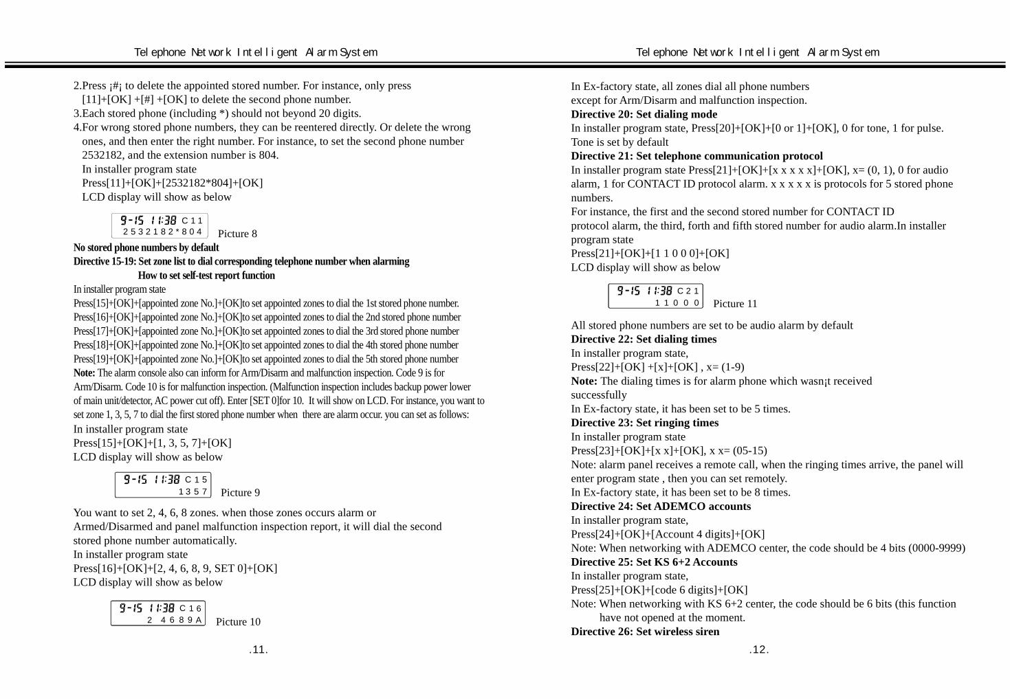
2.Press ¡#¡ to delete the appointed stored number. For instance, only press[11]+[OK] +[#] +[OK] to delete the second phone number.
3.Each stored phone (including *) should not beyond 20 digits.4.For wrong stored phone numbers, they can be reentered directly. Or delete the wrong
ones, and then enter the right number. For instance, to set the second phone number2532182, and the extension number is 804.In installer program statePress[11]+[OK]+[2532182*804]+[OK]LCD display will show as below
Picture 8No stored phone numbers by defaultDirective 15-19: Set zone list to dial corresponding telephone number when alarming
How to set self-test report function
Note:
In installer program statePress[15]+[OK]+[appointed zone No.]+[OK]to set appointed zones to dial the 1st stored phone number.Press[16]+[OK]+[appointed zone No.]+[OK]to set appointed zones to dial the 2nd stored phone numberPress[17]+[OK]+[appointed zone No.]+[OK]to set appointed zones to dial the 3rd stored phone numberPress[18]+[OK]+[appointed zone No.]+[OK]to set appointed zones to dial the 4th stored phone numberPress[19]+[OK]+[appointed zone No.]+[OK]to set appointed zones to dial the 5th stored phone number
The alarm console also can inform for Arm/Disarm and malfunction inspection. Code 9 is forArm/Disarm. Code 10 is for malfunction inspection. (Malfunction inspection includes backup power lowerof main unit/detector, AC power cut off). Enter [SET 0]for 10. It will show on LCD. For instance, you want toset zone 1, 3, 5, 7 to dial the first stored phone number when there are alarm occur. you can set as follows:
C 11 3 5 7
5Picture 9
In installer program statePress[15]+[OK]+[1, 3, 5, 7]+[OK]LCD display will show as below
You want to set 2, 4, 6, 8 zones. when those zones occurs alarm orArmed/Disarmed and panel malfunction inspection report, it will dial the secondstored phone number automatically.In installer program statePress[16]+[OK]+[2, 4, 6, 8, 9, SET 0]+[OK]LCD display will show as below
9C 1 6
2 4 6 8 A Picture 10
In Ex-factory state, all zones dial all phone numbersexcept for Arm/Disarm and malfunction inspection.
In installer program state, Press[20]+[OK]+[0 or 1]+[OK], 0 for tone, 1 for pulse.Tone is set by default
In installer program state Press[21]+[OK]+[x x x x x]+[OK], x= (0, 1), 0 for audioalarm, 1 for CONTACT ID protocol alarm. x x x x x is protocols for 5 stored phonenumbers.For instance, the first and the second stored number for CONTACT IDprotocol alarm, the third, forth and fifth stored number for audio alarm.In installerprogram statePress[21]+[OK]+[1 1 0 0 0]+[OK]LCD display will show as below
Directive 20: Set dialing mode
Directive 21: Set telephone communication protocol
C 11
21 000 Picture 11
All stored phone numbers are set to be audio alarm by default
In installer program state,Press[22]+[OK] +[x]+[OK] , x= (1-9)
Directive 22: Set dialing times
Note:
Directive 23: Set ringing times
Directive 24: Set ADEMCO accounts
Directive 25: Set KS 6+2 Accounts
Directive 26: Set wireless siren
The dialing times is for alarm phone which wasn¡t receivedsuccessfullyIn Ex-factory state, it has been set to be 5 times.
In installer program statePress[23]+[OK]+[x x]+[OK], x x= (05-15)Note: alarm panel receives a remote call, when the ringing times arrive, the panel willenter program state , then you can set remotely.In Ex-factory state, it has been set to be 8 times.
In installer program state,Press[24]+[OK]+[Account 4 digits]+[OK]Note: When networking with ADEMCO center, the code should be 4 bits (0000-9999)
In installer program state,Press[25]+[OK]+[code 6 digits]+[OK]Note: When networking with KS 6+2 center, the code should be 6 bits (this function
have not opened at the moment.
.11. .12.
Telephone Network Intelligent Alarm System Telephone Network Intelligent Alarm System
C 1 12 5 3 2 1 8 2 * 8 0 4
In installer program state,press[26]+[OK]+[wireless siren code 8 digits]+[OK]Note: The 8 digits siren code is marked at the back of siren if you want to erase sirencode, in installer program state,Press [26]+[OK]+[#]+[OK]No wireless siren code by default
In installer program state,Press[27]+[OK]+[0 or 1]+[OK].0 for close report, 1 for open report. Close report bydefault
In installer program state,Press[28]+[OK]+[zones 1-8]+[OK]For instance, you want to set 1, 2, 3, 4 zones to send a timing report to the main unit. Ininstaller program state,Press[28]+[OK] +[#]+[OK] to close timing communication.No timing communication by default
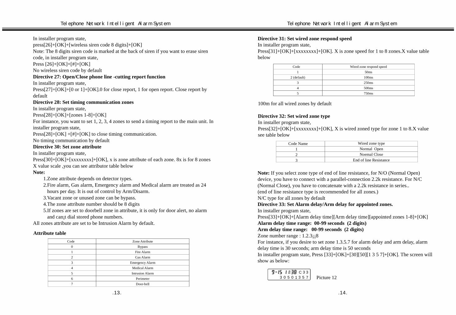
In installer program state,Press[30]+[OK]+[xxxxxxxx]+[OK], x is zone attribute of each zone. 8x is for 8 zonesX value scale ,you can see attributor table below
1.Zone attribute depends on detector types.2.Fire alarm, Gas alarm, Emergency alarm and Medical alarm are treated as 24
hours per day. It is out of control by Arm/Disarm.3.Vacant zone or unused zone can be bypass.4.The zone attribute number should be 8 digits5.If zones are set to doorbell zone in attribute, it is only for door alert, no alarm
and can¡t dial stored phone numbers.All zones attribute are set to be Intrusion Alarm by default.
Directive 27: Open/Close phone line -cutting report function
Directive 28: Set timing communication zones
Directive 30: Set zone attribute
Note:
Attribute tableCode Zone Attribute
0 Bypass1 Fire Alarm2 Gas Alarm3 Emergency Alarm4 Medical Alarm5 Intrusion Alarm6 Perimeter7 Door-bell
Directive 31: Set wired zone respond speedIn installer program state,Press[31]+[OK]+[xxxxxxxx]+[OK]. X is zone speed for 1 to 8 zones.X value tablebelow
Code Wired zone respond speed1 50ms
2 (default) 100ms3 250ms4 500ms5 750ms
100m for all wired zones by default
In installer program state,Press[32]+[OK]+[xxxxxxxx]+[OK], X is wired zoned type for zone 1 to 8.X valuesee table below
Directive 32: Set wired zone type
Note:
Directive 33: Set Alarm delay/Arm delay for appointed zones.
Alarm delay time range: 00-99 seconds (2 digits)Arm delay time range: 00-99 seconds (2 digits)
If you select zone type of end of line resistance, for N/O (Normal Open)device, you have to connect with a parallel-connection 2.2k resistance. For N/C(Normal Close), you have to concatenate with a 2.2k resistance in series..(end of line resistance type is recommended for all zones.)N/C type for all zones by default
In installer program state,Press[33]+[OK]+[Alarm delay time][Arm delay time][appointed zones 1-8]+[OK]
Zone number range : 1.2.3¡¡8For instance, if you desire to set zone 1.3.5.7 for alarm delay and arm delay, alarmdelay time is 30 seconds; arm delay time is 50 secondsIn installer program state, Press [33]+[OK]+[30][50][1 3 5 7]+[OK]. The screen willshow as below:
C 333 7100 5 3 5 Picture 12
.13. .14.
Telephone Network Intelligent Alarm System Telephone Network Intelligent Alarm System
Code Name123
Wired zone typeNormalNoemal
End of line Resistance
OpenClose
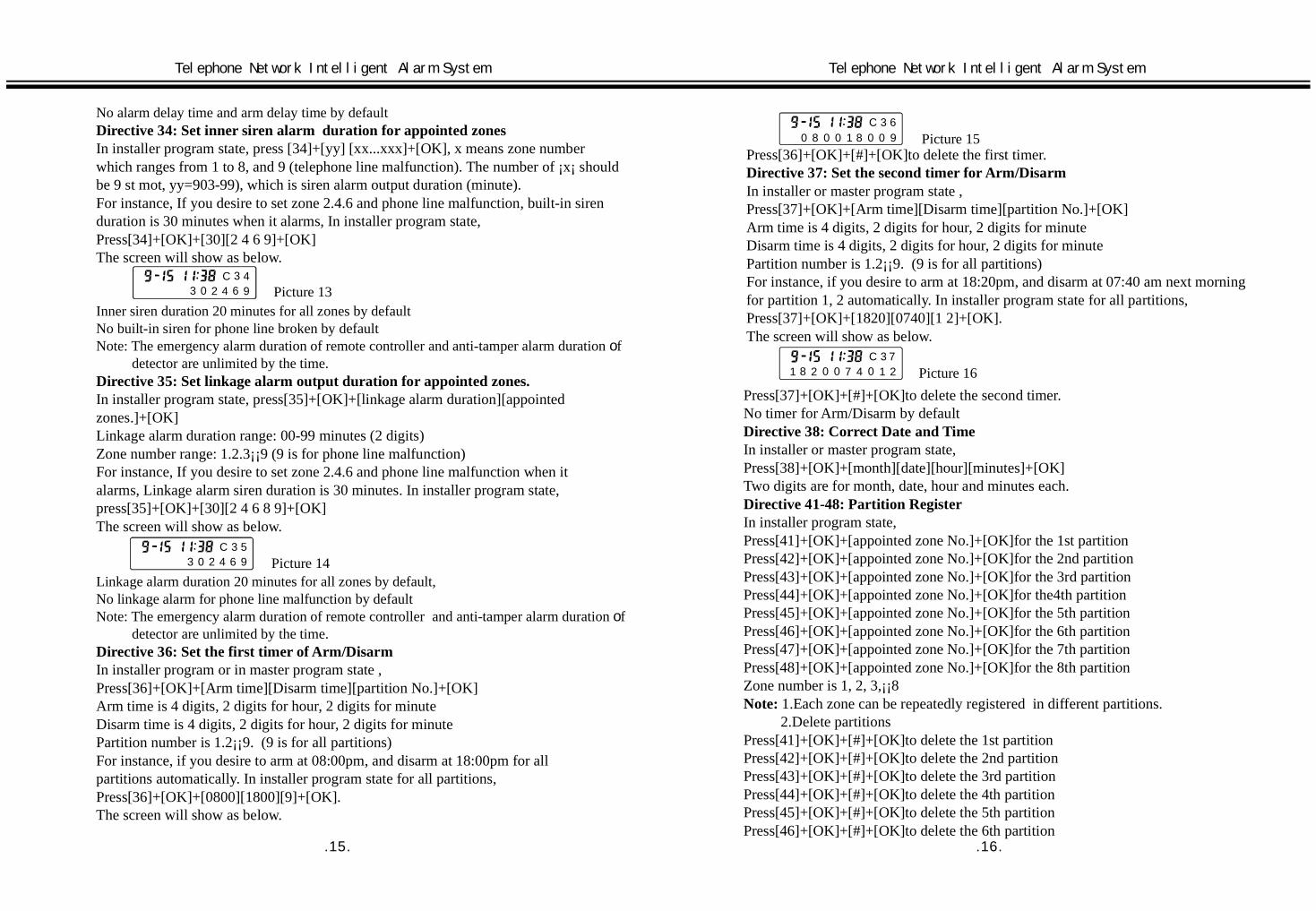
No alarm delay time and arm delay time by default
In installer program state, press [34]+[yy] [xx...xxx]+[OK], x means zone numberwhich ranges from 1 to 8, and 9 (telephone line malfunction). The number of ¡x¡ shouldbe 9 st mot, yy=903-99), which is siren alarm output duration (minute).For instance, If you desire to set zone 2.4.6 and phone line malfunction, built-in sirenduration is 30 minutes when it alarms, In installer program state,Press[34]+[OK]+[30][2 4 6 9]+[OK]The screen will show as below.
Directive 34: Set inner siren alarm duration for appointed zones
Inner siren duration 20 minutes for all zones by defaultNo built-in siren for phone line broken by defaultNote: The emergency alarm duration of remote controller and anti-tamper alarm duration f
detector are unlimited by the time.o
In installer program state, press[35]+[OK]+[linkage alarm duration][appointedzones.]+[OK]Linkage alarm duration range: 00-99 minutes (2 digits)Zone number range: 1.2.3¡¡9 (9 is for phone line malfunction)For instance, If you desire to set zone 2.4.6 and phone line malfunction when italarms, Linkage alarm siren duration is 30 minutes. In installer program state,press[35]+[OK]+[30][2 4 6 8 9]+[OK]The screen will show as below.
Directive 35: Set linkage alarm output duration for appointed zones.
Linkage alarm duration 20 minutes for all zones by default,No linkage alarm for phone line malfunction by defaultNote: The emergency alarm duration of remote controller and anti-tamper alarm duration f
detector are unlimited by the time.o
In installer program or in master program state ,Press[36]+[OK]+[Arm time][Disarm time][partition No.]+[OK]Arm time is 4 digits, 2 digits for hour, 2 digits for minuteDisarm time is 4 digits, 2 digits for hour, 2 digits for minutePartition number is 1.2¡¡9. (9 is for all partitions)For instance, if you desire to arm at 08:00pm, and disarm at 18:00pm for allpartitions automatically. In installer program state for all partitions,Press[36]+[OK]+[0800][1800][9]+[OK].The screen will show as below.
Directive 36: Set the first timer of Arm/Disarm
Press[36]+[OK]+[#]+[OK]to delete the first timer.
In installer or master program state ,Press[37]+[OK]+[Arm time][Disarm time][partition No.]+[OK]Arm time is 4 digits, 2 digits for hour, 2 digits for minuteDisarm time is 4 digits, 2 digits for hour, 2 digits for minutePartition number is 1.2¡¡9. (9 is for all partitions)For instance, if you desire to arm at 18:20pm, and disarm at 07:40 am next morningfor partition 1, 2 automatically. In installer program state for all partitions,Press[37]+[OK]+[1820][0740][1 2]+[OK].The screen will show as below.
Directive 37: Set the second timer for Arm/Disarm
Press[37]+[OK]+[#]+[OK]to delete the second timer.No timer for Arm/Disarm by default
In installer or master program state,Press[38]+[OK]+[month][date][hour][minutes]+[OK]Two digits are for month, date, hour and minutes each.
In installer program state,Press[41]+[OK]+[appointed zone No.]+[OK]for the 1st partitionPress[42]+[OK]+[appointed zone No.]+[OK]for the 2nd partitionPress[43]+[OK]+[appointed zone No.]+[OK]for the 3rd partitionPress[44]+[OK]+[appointed zone No.]+[OK]for the4th partitionPress[45]+[OK]+[appointed zone No.]+[OK]for the 5th partitionPress[46]+[OK]+[appointed zone No.]+[OK]for the 6th partitionPress[47]+[OK]+[appointed zone No.]+[OK]for the 7th partitionPress[48]+[OK]+[appointed zone No.]+[OK]for the 8th partitionZone number is 1, 2, 3,¡¡8
1.Each zone can be registered in different partitions.2.Delete partitions
Press[41]+[OK]+[#]+[OK]to delete the 1st partitionPress[42]+[OK]+[#]+[OK]to delete the 2nd partitionPress[43]+[OK]+[#]+[OK]to delete the 3rd partitionPress[44]+[OK]+[#]+[OK]to delete the 4th partitionPress[45]+[OK]+[#]+[OK]to delete the 5th partitionPress[46]+[OK]+[#]+[OK]to delete the 6th partition
Directive 38: Correct Date and Time
Directive 41-48: Partition Register
Note: repeatedly
.15. .16.
Telephone Network Intelligent Alarm System Telephone Network Intelligent Alarm System
C 3 43 0 2 4 6 9 Picture 13
Picture 14C 3
3 0 2 4 6 95
Picture 15C 3 6
0 0 900 08 81
7C 3
00 081 2 1472 Picture 16

Press[47]+[OK]+[#]+[OK]to delete the 7th partitionPress[48]+[OK]+[#]+[OK]to delete the 8th partitionFor instance, you appointed zone 1, 3, 5, 7 to register in the first partition. In installeror master program state ,Press[41]+[OK]+[1, 3, 5, 7]+[OK]for the 1st partitionThe screen display will show as below.
3.1-8 user's codes and 1-8 remote controllers are defined to be 1-8 users, and differentusers can operate corresponding zone independently
In installer program state,Press[50]+[OK]to enter the record menu, and press[0]+[OK]to start record messagefor 10 seconds. Close microphone to record and press [OK] to finish. Press[1]+[OK]to display record message. In record menu, press[0]+[OK]to record repeatedly.
In installer program state,Press[60]+[OK]to enter register remote controller menu, and enter code number1 to 8 for corresponding remote controller and [OK] key to confirm.In remote controller registering menu.Press[1]+[OK]to register the 1st remote controllerPress[2]+[OK]to register the 2nd remote controllerUp to 8 remote controllersIf the code is vacant, the screen will show as picture18 , if the code has beenregistered, It will show as Picture19Register a remote controller in vacant code, press Arm key on remote controller,¡Bi-Bi-¡ indicate register successfully. If the code have been registered, there is a¡Di¡¡ indicative alert ,in that menu, Press[#]+[OK]to delete the original registerfirstly, then register it the same as vacant code.Press[1]+[OK]+[#]+[OK]to delete the 1st remote controllerPress[2]+[OK]+[#]+[OK]to delete the 2nd remote controllerUp to 8 remote controllersIn installer program state,Press[69]+[OK]+[#]+[OK]to delete all registered remote controllers.
Directive 50: Record your message
Directive 60: Register/delete remote controller
Press[71]+[OK]to enter the1st zone register.Press[1]+[OK]to register the 1st sensorPress[2]+[OK]to register the 2nd sensorPress[3]+[OK]to register the 3rd sensorPress[72]+[OK]to enter the 2nd zone register.Press[1]+[OK]to register the 1st sensorPress[2]+[OK]to register the 2nd sensorPress[3]+[OK]to register the 3rd sensor¡¡ Up to 8 zone registersFor instance, register the third sensor in the second zone.In installer program state,Press[72]+[OK]to enter the second zone sensor register. Press[3]+[OK]to enterthe third code.Picture20 for vacant code, Picture21 for registered code.
Register a sensor in vacant code, trigger sensor to send a signal to alarm console,Bi-Bi-means register successfully.If the code has been registered, you have to delete it before registering new sensor.Press[#]+[OK]to delete previous registered, then register it the same as vacant code.In installer program state,Press[79]+[OK]+[#]+[OK]to delete all registered sensors.Press[71]+[OK]+ to enter the 1st zone register.Press[1]+[OK]+[#]+[OK]to delete the 1st sensorPress[2]+[OK]+[#]+[OK]to register the 2nd sensorPress[3]+[OK]+[#]+[OK]to delete the3rd sensorPress[72]+[OK]to enter the 2nd zone register.Press[1]+[OK]+[#]+[OK]to delete the 1st sensorPress[2]+[OK]+[#]+[OK]to delete the 2nd sensorPress[3]+[OK]+[#]+[OK]to delete the 3rd sensor ¡¡
In installer program state,Press[80]+[OK]+[#]+[OK], the alarm console will come back to default state.
Note: Both installer code and master code can be programmed for those marked¡*¡ in remark column. Others have to be programmed by installer code
Directive 80: Come Back To Default State.
5.3 Program Table
.17. .18.
Telephone Network Intelligent Alarm System Telephone Network Intelligent Alarm System
C 4 11 3 75 Picture 17
Picture 18 Picture 19
Picture 20 Picture 21
Note: 1: when learning remote controller, main unit will recognize automatically tosee if this code has been learned, if this remote controller has been learned,Then the main unit will refuse to learn this code, and it will make a ¡Di...¡ Sound.
2: After learning, you should test to see if this code has been learned successfully.
Directive 71-78: Register/delete sensorsIn installer program state,
3: 1-8 remote controller and 1-8 user¡s code are defined to be 1-8 users, and theycan separately operate in 1-8 sub zones.
C 6 0 C 6 0A C 9 0 A B
C 7 2 C 7 21 3 5 7 B C
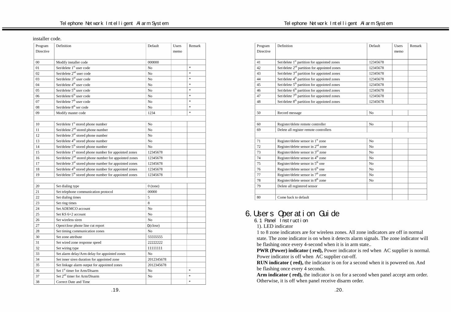
installer code.ProgramDirective
Definition Default Usersmemo
Remark
00 Modify installer code 00000001 Set/delete 1st user code No *02 Set/delete 2nd user code No *03 Set/delete 3rd user code No *04 Set/delete 4th user code No *05 Set/delete 5th user code No *06 Set/delete 6th user code No *07 Set/delete 7th user code No *08 Set/delete 8th ser code No *09 Modify master code 1234 *
10 Set/delete 1st stored phone number No11 Set/delete 2nd stored phone number No12 Set/delete 3rd stored phone number No13 Set/delete 4th stored phone number No14 Set/delete 5th stored phone number No15 Set/delete 1st stored phone number for appointed zones 1234567816 Set/delete 2nd stored phone number for appointed zones 1234567817 Set/delete 3rd stored phone number for appointed zones 1234567818 Set/delete 4th stored phone number for appointed zones 1234567819 Set/delete 5th stored phone number for appointed zones 12345678
20 Set dialing type 0 (tone)21 Set telephone communication protocol 0000022 Set dialing times 523 Set ring times 824 Set ADEMCO account No25 Set KS 6+2 account No26 Set wireless siren No27 Open/close phone line cut report 1(close)28 Set timing communication zones No30 Set zone attribute 5555555531 Set wired zone response speed 2222222232 Set wiring type 3333333333 Set alarm delay/Arm delay for appointed zones No34 Set inner siren duration for appointed zone 201234567835 Set linkage alarm output for appointed zones 201234567836 Set 1st timer for Arm/Disarm No *37 Set 2nd timer for Arm/Disarm No *38 Correct Date and Time *
41 Set/delete 1st partition for appointed zones 1234567842 Set/delete 2nd partition for appointed zones 1234567843 Set/delete 3rd partition for appointed zones 1234567844 Set/delete 4th partition for appointed zones 1234567845 Set/delete 5th partition for appointed zones 1234567846 Set/delete 6th partition for appointed zones 1234567847 Set/delete 7th partition for appointed zones 1234567848 Set/delete 8th partition for appointed zones 12345678
50 Record message No
60 Register/delete remote controller No69 Delete all register remote controllers
71 Register/delete sensor in 1st zone No72 Register/delete sensor in 2nd zone No73 Register/delete sensor in 3rd zone No74 Register/delete sensor in 4th zone No75 Register/delete sensor in 5th one No76 Register/delete sensor in 6th one No77 Register/delete sensor in 7th zone No78 Register/delete sensor in 8th zone No79 Delete all registered sensor
80 Come back to default
ProgramDirective
Definition Default Usersmemo
Remark
6.Users Operation Guide
1). LED indicator1 to 8 zone indicators are for wireless zones. All zone indicators are off in normalstate. The zone indicator is on when it detects alarm signals. The zone indicator willbe flashing once every 4-second when it is in arm state..
Power indicator is red when AC supplier is normal.Power indicator is off when AC supplier cut-off.
the indicator is on for a second when it is powered on. Andbe flashing once every 4 seconds.
the indicator is on for a second when panel accept arm order.Otherwise, it is off when panel receive disarm order.
6.1 Panel Instruction
PWR (Power) indicator ( red),
RUN indicator ( red),
Arm indicator ( red),
.19. .20.
11111111
0
Telephone Network Intelligent Alarm System Telephone Network Intelligent Alarm System

It is on when an emergency alarm occurs by pressingEmergency key on remote controller. It is off when the system is disarmed.Emergency indicator ( red),
1 2 3
654
7 8 9
0 #*
编程
确认
设防
复位
Z1 Z2 Z3 Z4
Z5 Z6 Z7 Z8
运行 交流 布防 紧急
Panel of alarm host diagram
LCD Keyboard
MIC LED Indicator
Box Lock
Speaker
2). LCD displayTwo lines for LCD display, up-line is for time and 3 characters, down-line is for 11characters display. After powered on ,it inspectsautomatically, and the LCD displayis for initialization (see picture 22)
Picture 22
Read alarm information on screen when system occurs alarm. For instance, a firealarm in the 8th zone (see picture 23below).
Picture 23
Alarm time ¡ September 15th , 11:38¡¡N01¡ is the first alarm record.¡Z08¡ is the 8th zoneFire means fire alarm.The screen can be scrolled for more alarm records,( scrolling once every 5 seconds)
is Arm keyis Disarm keyis Emergency key, on-site alarm will be
activated and dial all stored phones bypressing emergency alarm.
3). Remote controller
AntennaIndicator
Disarm
Arm
Emergency
KS-12A Remote Controller
4). Display content definition.
Display content Definition Display content DefinitionArm Arm Disarm DisarmTEL Error Telephone line
failureTEL Back Telephone line
come back tonormal
AC Loss AC power cut-off AC Back AC power comeback to normal
MBAT Low Main unit batterypower low
MBAT Back Main unit batterycome back tonormal
Zx Low(x=1¡ 8)
Sensor in x zonepower low
Zx L Back(x=1-8)
X zone sensorpower come backto normal
Zx Fire (x=1¡ 8) Fire alarm in x zone Zx Gas (x=1¡ 8) Gas leakage in xzone
Zx (x=1¡ 8)EMC
Emergency alarm inx zone
Zx (x=1¡ 8)Medical
Medical alarm inx zone
Zx (x=1¡ 8)Theft
Intrusion alarm in xzone
Zx Peri(x=1¡ 8)
Perimeter alarmin x zone
Zx Tamper(x=1¡ 8)
Tamper alarm in xzone
Zx Com err(x=1¡ 8)
Communicationfailure in x zone
Zx Open (x=1-8) X zone open infraredsensor
Zx Close (x=1-8) X close theinfrared sensor
Zx EMC(x=1¡ 8)
Emergency alarm inx user
Ux Duress(x=1¡ 8)
Duress alarm inx user
Host Tamper Main unit tamperalarm
5). Sound indicator
Indicator DefinitionA short ¡Bi-¡ Valid indicator for keyboard indicatorTwo short ¡Bi-Bi-¡ Program operation correctly or arm indicatorFour short ¡Bi-Bi-Bi-Bi-¡ Power on inspect--self or disarm indicatorA long ¡Di----¡ The wrong program indicatorA short ¡Di-¡ every second Phone line failure indicatorA short ¡Bi-¡ every two second Delay arm alert indicatorA short ¡Di-¡ every two second Delay alarm alert indicatorA long ¡Bi----¡ every 1 minutes Main unit battery low indicator
.21. .22.
Telephone Network Intelligent Alarm System Telephone Network Intelligent Alarm System
S
S
N 0 1Z 0 8 F i r e
Welcome

6.2 Code
6.3 Arm/Disarm
6.4 Alarm operation
It is used to set alarm console. Default code is ¡000000¡.It is used to Arm/Disarm/ modify user code/ correct date and
Arm/Disarm timer. Default code is ¡1234¡.system can be programmed up to 8 user codes (no user code by
default). With user code to Arm/Disarm corresponding partition.
It is composed of last digit of user code plus 1, (for example, the user code is¡1234¡. The duress code is ¡1235¡). If the last digit of user code is 9, the lastdigit of duress code shall be 0 (for example, the user code is 1239. the duresscode is 1230). The user code is used when users are in duress. The users cancancel alarm and disarm system by duress code, but the system also send outthe alarm information through telephone to ask for help at the same time.
1). The remote controller programmed to arm/disarm for different partitions.Press key to Arm, Press key to disarm.
2) Arm/disarm for different partitions on panel keyboard.the partition is in disarm state, press partition number and SET key.
For example, you want to quickly arm partition 8 (partition 8 is in disarm state),just press 8 and ¡SET¡ key on panel keyboard. ,Then the partition 8 is armed.
Note: you can arm all partitions by pressing ¡8¡,if the pa rtition you choose is in armstate, the indicate ¡enter the code¡
In standby time, press ¡set¡key,it will indicate that ¡pleaseenter code¡,then press [4 digits user code ]+[OK ].If the code you entered is the sameas the preset user code, it will enter disarm state, oppositely, it will enter arm state. Ifthe code is wrong, it will indicate that ¡The code is wrong ,please re-enter the code¡.If the code you entered is wrong for three times continuously, it will alarm on spotand lock the keypad for 1 minute.
: Different user code only can operate the corresponding zones. If you operateby entering master code, press [4 digits master code ]+[partition No] to arm/disarmthe different partitions. If the partition No is ¡9¡ or you don¡t enter any No, thatmeans you arm/disarm all partitions.
3). Arm/Disarm through timer.4). Arm/Disarm through remote telephone with user code or master code.
the user code Arm/Disarm is only for corresponding partition. Master coder isfor all partitions
During Arm operation, the sound ¡Bi- Bi-¡means Arm, the Armindicator light will be on and the corresponding zone will enter arm state. Forthe delay Arm zones, the panel won¡t enter arm state until delay time expired.During the delay time ,there is a sound ¡Bi-¡ very two seconds to alert users toleave before delay time arrive.
1). Intrusion alarmThe zone attribute in ¡Intrude Alarm or Perimeter alarm¡, They won¡t activateuntil alarm console in Arm state. So don¡t forget to ARM the alarm system
1)The installer code:2)Master code:
3)User code:
4)Duress code.
Quick Arm,
Routine Operations:
Note
Note:
Note:
before you leave the place.2) Emergency Alarm
Press key for emergency help in urgent situation, the alarm activate byemergency key will dial all stored phone numbers and start on-site siren.
3) Duress alarmWhen you are in dress by robber, press the duress code. The alarm system willbe disarmed, but send duress information through phone dialer.
If your system setup is in delay alarm state, the duress alarm will delay.During the time ,the console will be Di- Di- every two seconds. You can Disarmsystem.
1)ADEMCO alarm center processing automatically2)Users processing
When alarm console dials the phone number you set . It plays the recordedmessage your stored. And give you 5 seconds after displaying message.During 5 seconds, you are able to press 5#.4#.2# or 0# on your phone or mobilephone.Press 5# to display message you stored repeatedly.Press 4# to listen to 30 seconds sound from alarm console location. During thetime, any operation is ineffective. You are able to enter other commands(see appendix 4) after 30 seconds. If there are not any operations in 30 seconds,
the system will dial next phone number your set .Press 2# to deactivate alarm and disarm the alarm console. It will not dial otherphone numbers you stored any more.Press 0# to exit this call, and dial next phone number your stored. But system willdial this number later in turn.If you receive call from alarm console and no do any operations. It will displaymessage 5 times repeatedly and dial next phone number.
¡Ding-Dong, please attention!![Message you record], zonenumber and alarm attribute¡.
You are able to dial phone numbers that alarm console located through yourphone or mobile phone. When the ring times you set arrives, the alarm consolewill indicate that ¡Please enter code ¡, then you have to ent er user code and # onyour phone keyboard. (If no operation beyond 5 seconds, there is anotherindicator ¡Please enter code¡. It will repeat three times and then hang up.)One sound indicator ¡Du-¡ means the code is correct. Then you are able to enterdirective you wanted. If no operation beyond 30 seconds, the phone will be hungup. If incorrect code was entered three times continuously, the phone will behung up. You also be able to press 4# to listen to 30 seconds sound from alarm
Note:
Message format:
6.5 When you receive alarm
6.6 Remote setup
.23. .24.
Telephone Network Intelligent Alarm System Telephone Network Intelligent Alarm System

Appendix 4Directive Definition Command Definition1# Arm 2# Disarm3# Start up on-site siren 4# Listen to on-site sound6# Start up linkage device 7# Shut down linkage device8# Shut down on-site siren 0# exit
6.7 Record Inquiry
≤
≥400m)≥200m)
( ≥ )0℃-55℃ 40-70%
7.2≤5uA
≤10mw 433MHz
1)In standby time, press[1]+[OK]to read the latestArm record, LCD display will show as below. Thetime is the latest arm time. ¡U02¡tell you that it isarmed by the second user.
2)In standby time, press[2]+[OK]to read the latestDisarm record, LCD display will show as below.The time is the latest disarm time. ¡U02¡tell youthat it is disarmed by the second user.
3)In standby time, press[3]+[OK]to quickly read alarm record up to 20 pieces, andpress[*]or[#]for up or down pager
7.1 Alarm ConsoleSize:26.4cm X 26cm X 8cm (LXWXH) Excluding length of antennaWeight:3KG (Excluding backup battery)Power Supply:AC220V¡15%, Battey:12V/7AhAuxiliary Output Power: <550mASiren Output Current: < 1.5ATotal Output Current: 1.5A (the current of outer current should not over it)Wireless Working Frequency:433MHzWireless Communication Distance:The distance between PIR detector and alarm host (in open area

.27. .28.
1. wrongly connect bothnegative terminal and signalterminal for the zone that isnot sensor connected.
For the zones where have notsensor connected are asked toconnect signal terminal correctlyor bypass them.
Communication failure whilealarming or dialing
Telephone communicationprotocol is not programmed.
Program the telecommunicationprotocol rightly
The telephone can not dialwhile alarming
The telephone line and out lineare connected oppositely.
Correct the telephone hole and linehole .
Telephone Network Intelligent Alarm System Telephone Network Intelligent Alarm System
Wireless Infrared Sensor
User¡s ManualWireless Passive Infrared Sensor adopts advanced digit signalprocessing. It is with automatic temperature compensation technology, Lower poweralert and timing communication report. It detects human infrared heat energy to emitwireless digit signals to activate alarm host. It is advantage of low false alarm rate ,stable and easy installation.
1.Adopt dual infrared sensor, high sensitivity.2.Single-chip intelligent digit processing3.Double-channel intelligent signal processing4.Low power consumption design, static current 50¦A, anti-pet,
anti-electromagnetism interference and low false alarm rate .5.Three levels of sensitivity.6.Automatic temperature compensation7.Adapter DC9V-12V is available. Automatically switch between inner power and
external power.8.With power lower alert and send signal to alarm host to report.9.Timing communication report and ON/OFF report.
1. Main Functions And Features
≤
2. Technical Parameter
3. Component Description
1.Detective distance 8m2.Detective angle: 90¡3.Working Voltage: DC6V (4pcs No.7 dry batteries),
and external power (adapter):DC9V
33.92
≤
~12V.4.Working Current:Power supplied by battery, Standardcurrent≤50μA, Alarm currenct≤15mAPower supplied by the adapter, Standardcurrent≤5mA, Alarm currenct≤15mA
5.Blocked time when it is power on:100seconds6.Emission time: 3 seconds7.Emission Frequency: 43 MHz8.Emission power≤70mW9.Physical size: 110mm X 60mm X 45mm10.Working temperature:-25℃~+65℃
3.1 Working Mode:
A.Test Mode:
B.Standard Mode:
C.Power Saving Mode:
Note:3.2 Tamper:
There are three Modes of Switch¡Testing Mode, Standard Mode, PowerSaving mode.
After it sends a signal, the sensorwon¡t send a new signal until 5seconds. It is recommended todebug. This mode run morepower.
After it sends a signal, the sensorwon¡t send a new signal until 60seconds. It is recommended towork daily.
After it sends a signal, the sensorwon¡t send a new signal until 240seconds. It is used in marketingplace where have more people inand out.
The mode shall be changed in power off state (including batteries power).When DOS is opened or destroyed illegally, infrared detector
will send signals to alarm host and activate alarming. Tamper alarm canbe activated in 24 hours a day. Even the sensor is in power off state.
3.

Telephone Network Intelligent Alarm System Telephone Network Intelligent Alarm System
.29. .30.
Adjust switch to ¡ON¡ position, the detector will start towork, adjust switch to¡OFF¡ position, the detector will stop working andreport to the host at the same time.
DC9V~12V is available (polarity **), External powersupplied and inner power supplied can be changed automatically.
4.1.1 The infrared detector has the highest sensitivity when a human body movesparallel with the mirror surface and the sensitivity is the lowest when ahuman body moves vertically against the mirror surface. So the angle andheight against the horizontal surface should be noted during installation,which will greatly effect the range of the defense area. The height shall be2 meters or so and the angle against the wall should be parallel..
4.1.2 Stand off sunshine and other break-out light sources (e.g. car light)4.1.3 Stand off the warm or cold sources, e.g., warm air or cold air outlet, air
conditioning outlet, electric radiators, air cooling machines and etc. standoff the windows.
4.1.4 There are no barriers within the defended area of a detector.4.1.5 If infrared detector works in temperature which is near to human
temperature, the detective effect is inefficient. So in this instance, Infrareddetector is suggested to be installed in lower temperature in that area.
4.1.6 In interference instance, infrared detector is suggested to be adjusted tolower sensitivity position.
4.1.7 Infrared detector is asked to be stable on the wall.Open the top cover of detector, select the sensitivity level and working modeaccording to security requirements.
3.3 Power on/off:
3.4 External DC Input:
4.1. Installation Requirements
4.2 Install 4pcs No.7 batteries according to battery case remark..then adjustON/OFF switch to ¡ON¡ position, and fix it on the wall.
4. Installation Requirements And Diagram
1.Open cover as picture showsTop View
2. Transmitting Code Jumper Working Mode SelectNormal Mode Sensitivity 8m 6m
3.Press universal ballinto universal bearer.To void damaged,please energize onaverage.
4.Fix universal bracketwith nail on 2m overhorizontal.
5.Fix infrared detectorin universal bracket.
6.top view, adjustingdetector area rightand left,
7.side view, adjustingup and downinstallation finisheddetector
4.3. Indicator
4.4. Simulating Demo
5.Note
1. Instruction
Alarm Indicator: When alarm happens, alarm indicator will be flashing LowerPower Indicator: When power is low, lower power indicator will be on
After powered on for 100 seconds, human body motions by 0.75m/S by8-10m in distance. Its alarm indicator is on and it activates alarming, whichmeans the installation is right and success.
5.1.1 To make sure its sensitivity, infrared sensor is not allowed to be touched byhand. And it should be keep clear. If the surface is dirty, powering it off andclean it with a cotton ball dipped in 75% alcohol.
5.1.2 Test infrared detector periodically5.1.3 This infrared detector can prevent theft , but it don¡t promise there are no
any risks at all. For security, users are asked to use this products correctlyand improve daily alert
Wireless door sensor matches with a magnet. It sends alarm signals toalarm console when both parts separated. The door sensor is designed in micropower consumption with low power alert. The wireless transmitter adopts SAWF.It is much stable. The transmitting distance in open area can reach to 250m ormore.
Wireless Door SensorUser¡s Manual

Telephone Network Intelligent Alarm System Telephone Network Intelligent Alarm System
.31. .32.
Warnning: Limits of this safe system
As an advanced technical guard system, although it can reduce the occurrence oftheft. robbery and fire, it can not promise to have no any above-mentiond accidentshappens or have no any personnel casualty or property losses happens. And weinvite you understanding that any alarm system ,whether it is used in business or athome, it may alarm wrongly or failure to alarm because of various reasons.Karrssn remind you to pay attention to the following possible reasons:1.The system is not armed because of carelessness.2.User or installation personnel misunderstand the user¡s manual or operate
wrongly so that the system can not work normally.3.Intruder intrude the place where is beyond the detect areas or he can pass by
the alarm detector or make it malfunction. Passive infrared detector only cannot detect hidden places, like behind the wall. inside ceiling. inside floor. behindthe door. glass partition. glass door or behind the glazing .
4.The detect sensitivity of passive infrared detector will automatically changeaccording to the changed environment temperature .when the temperature ofprotected area reach to 32 -40 ,the performance of infrared detector(detect distance) will reduce. So we suggest you to check its workingperformance carefully when it reaches to such a temperature, and thenadjusting it.
5.There are no power or the battery is used out or damaged.6.The alarm trumpet is installed at the other side of the door closed,so it may
not be able to warn or wake the sleeper.7.There are something wrong with telephone line which transfer alarm signals
to the alarm center ,or the lines are busy so that it can not transfer signals intime.
8.When there are someone intrude ,the common reason why the system can¡talarm is that the system don¡t get abnormal maintenance . Like otherelectrical equipments , the electronic elements of this equipment also maybe damaged. Therefore, user should check the system periodically everyday.
9.Other unpredicted reasons.If you don¡t agree with the above clauses, within three days from you purchase,you can send it back if only it is not damaged, and we will refund all money.Otherwise, we view it as that you agree with the above clauses.You should know that the alarm equiptment is not insurance substitution .Sothe users must be carefull to protect your life and property.
℃ ℃
2. Installment
3. Note
4. Component Diagram
Remove the paper on double-faced glue on both door sensor and magnet. Gluesensor and magnet in proper place you want .Make sure the antenna of doorsensor is upright(up or down).