why stick with adhesives for quality in high-volume applications?
TRANSCRIPT

1
Why Stick with Adhesives for Quality in High-Volume Applications?
Gilbert B. Chapman II
Advanced Transportation Technologies and Tessonics Corporation
38671 Greenbrook Ct., Farmington Hills, Michigan 48331
248 324-5037
1. Introduction
Advances in materials and processes technologies provide opportunities to expand applications
for these technologies into manufacturing systems whenever improvements to cost, quality and
environmental impact can be realized and recognized. The implementation of these new or
emerging technologies often requires concomitant advances in manufacturing equipment and
methodologies; therefore windows of opportunity must be sought where these advances can be
justified. Furthermore, successful implementations require an optimal fit among the design,
material and process for each component implemented, as illustrated in Figure 1, and they must
fit, or meet the design intent, in the application. A graphic illustration of this second concept is
shown in Figure 2. This is especially true when these emerging materials and processes
technologies are applied in high-volume manufacturing environments where high quality and
low cost are essential elements for success.
Figure 1. There must be an optimal fit among processes, material and design.
A simple example of the application of this concept in adhesive bonding is that bond joints
must be located and designed to be loaded in shear in order to derive maximize benefit from
their performance, and the overlap area bonded must be sufficient to provide the required

2
performance, given the specifications of the adhesive material, its application process and
compatibility, the intended static and dynamic loads, as well as appearance and environment.
Figure 2. The design, material and process must fit the application.
Research in the physicals sciences and developments in materials engineering are essential
sources of knowledge in the development of new materials and processes used to build
vehicles and other engineering structures. Such research is also a significant source of
knowledge to support the development of a variety of adhesive bonding technologies and
materials-characterization technologies for evaluating the characteristics and integrity of
bonded components, structures and processes before, during and after use.
The research and development reported herein seeks to contribute to this knowledge, and add
support for a wider usage of the adhesive joining process by discussing the adhesive bonding
needs and requirements of a high-volume, cost-sensitive industry, and by presenting
nondestructive evaluation (NDE) technology that is useful in supporting quality and reliability
improvements in adhesive bonding. This dual approach thus offers a simultaneous pathway to
the enhanced performance and appearance of bonded structural components, as well as vehicle
weight reduction for improved energy efficiency and environmental quality.
2. The Need for Adhesive Bonds
Adhesive bonding provides a method of joining similar and dissimilar materials, and thus
allows vehicle designers and manufacturers wider options and more flexible choices in
materials, and material combinations, to optimize tvehicledesign and performance.
Adhesive bonding helps meet the need for vehicle weight reduction to improve fuel efficiency.
The use of advanced designs, materials and processes is increasing in order to accomplish
weight reduction for improved fuel efficiency. The increased use of these materials and
concomitant processes in transportation vehicles has resulted in more reliance on advanced

3
joining technologies to provide enhancement in the design, assembly and performance of
current components and vehicles. Among these advanced joining technologies, the use of
adhesive bonding has rapidly expanded. This expansion, although facilitated by advances in
technology, is motivated mainly by the unrelenting drive to reduce weight in order to conserve
energy. Moreover, the use of adhesive bonds to improve such thickness-related characteristics
as weld corrosion, vehicle stiffness, joint load distribution, vehicle noise and vibration, makes
this joining technology even more attractive, as material thickness is minimized to reduce
weight.
Adhesive bonding helps to improve quality in such areas as corrosion resistance, noise
reduction, vibration dampening, fatigue life extension, improved body stiffness and more
flexible styling, all without compromising the vehicle capacity, appearance and affordability to
which customers have become accustomed. There appears to be an empirical exponential
relationship between vehicle weight and fuel efficiency data, confirming that weight reduction
in the vehicle body can allow weight reduction in other vehicle components, such as the
chassis, power train and so on. Therefore, the use of adhesive bonding as a structural joining
method is expanding to support these advancements in materials and joining technologies. The
growth of adhesive bonding in fields such as aerospace, automotive, construction,
infrastructure, medical, packaging, sporting equipment and other applications has been
significant, and the demand for adhesives is expected to continue to increase [1].
3. Advantages of Adhesive Bonds
These attractive attributes of adhesive bonding, and its applicability to a wide spectrum of
materials, have contributed to its growth as a primary and secondary method of joining metal,
plastic and polymer composite materials to similar as well as to dissimilar materials. An
example of the latter is shown in Figure 3.
The expansion of adhesive bonding as a method of joining in vehicle body structures has also
grown as a result of the development and implementation of more improved adhesive bonding
technologies that lead to a more wide-spread use in rapid manufacturing and assembly
processes. Furthermore, other rapid joining methods, such as resistance spot welds and
mechanical fasteners, are augmented by the use of adhesive bonds that provide enhanced load
distribution in the joint, leading to a longer fatigue life and improved stiffness, noise and
vibration characteristics of the component or assembly. Adhesive bonding, with its enhanced
load distribution, also allows the use of thinner sheet metals and lighter body materials such as
aluminum, polymer composites and plastics, as these less-dense materials are implemented to
accomplish weight reduction.

4
Figure 3. An example of joining requirements placed on adhesives to assure the high-
quality performance and appearance of such a multi-material vehicle body component
made from polymer composite, metal and thermoplastic materials.
The needs and requirements of the high-volume, low-cost automotive industry, along with the
adhesive bonding research and development reported herein, should be helpful in guiding the
development and implementation of improved adhesive bonding technologies that fulfill the
needs and meet the requirements of high-volume, mass-production manufacturing operations,
such as the automotive industry, and thereby support the continuing development and
application of high-performance, lightweight, low-cost materials, and the processes associated
with producing, fabricating and joining them in a manner to accomplish weight reduction,
without sacrificing other desirable characteristics.
4. Problems with Adhesive Bonds
Because of these advantages, the growth of adhesive bonding as a joining methodology
continues in high-volume, mass-production operations such as the automotive industry. The
growth continues while the reliability of adhesive bond joints in automotive assemblies often
remains inconsistent. The many causes can be summarized into the following five categories:
1. Correct Chemistry
2. Proper placement of the adhesive
3. Full width delivery
4. Adhesion to the Substrate
5. Proper Cure

5
These five categories can be examined to identify a long list of variables that contribute to the
significantly large and unacceptable variations in bond-joint strength that occur after the
production process has been launched, and after process control and capability is established,
occur because adhesive bond quality is subsequently impacted by many factors with variability
not precisely controlled in the manufacturing environment. In fact, the variability of many of
these factors cannot be controlled in the manufacturing assembly facility where the adhesive
bonding process is performed, because they are determined in the supply chain where the
processes are performed before entering the domain of the manufacturing assembly facility. An
incomplete list of 16 such factors is shown here:
1. Adhesive-adherend (substrate) compatibility
2. Chemical state of the adhesive material
3. Mixing of the components of the adhesive material
4. Substrate surface condition (chemical, morphological, wetting)
5. Pre-through-post application environment (temperature, humidity, dust, etc.)
6. Application of the adhesive material for full bond coverage, quantity and location
7. Inter-penetration of adhesive into the adherend, wetting
8. Mechanical bonding of adhesive to the adherend
9. Molecular bonding of adhesive to the adherend
10. Adhesion strength between adhesive and adherend
11. Coordination, or fit, between mating contours
12. Adhesive curing conditions: temperature, pressure, time, chemistry, relative
movement
13. Constant clamping force to compensate for adhesive shrinkage during post-cure
cooling
14. Adhesion and/or cohesion of adherend surface layer to its sub-surface substrate
15. Tensile and shear cohesion within the adhesive layer
16. Subsequent assembly and painting process with thermal and mechanical
variations
The level of sensitivity of the effectiveness of the bonding process to most of these factors is
not completely known, but a significant fraction of these factors are known to vary in a typical
pre-production automotive supply chain, as well as in the manufacturing assembly
environment, and each factor, like links in a chain, can adversely affect the adhesive bond
quality.
An example of these wide variations in adhesive bond strength along a typical bond line is
shown in Figure 4. This example is from a bond-joint segment that is deemed to have
acceptable bonding, with a bond merit factor of 0.79 [2, 3, 4]. This adhesive bond joint test
data was acquired from lap-bonded specimens, tested in shear by tension loading, as
schematically illustrated on the left side of Figure 4, according to American Society for Testing
Materials (ASTM) Standards [5, 6]. Some sample sets have yielded results with coefficients of
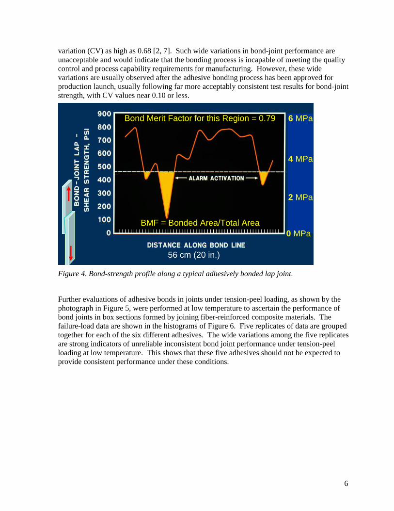
6
variation (CV) as high as 0.68 [2, 7]. Such wide variations in bond-joint performance are
unacceptable and would indicate that the bonding process is incapable of meeting the quality
control and process capability requirements for manufacturing. However, these wide
variations are usually observed after the adhesive bonding process has been approved for
production launch, usually following far more acceptably consistent test results for bond-joint
strength, with CV values near 0.10 or less.
6 MPa6 MPa
2 MPa
4 MPa
0 MPa
56 cm (20 in.)
l l l l l l l l l l l l l l l l l l l l l l l l l l l l l l l l l l l l l l l l l l l l l l l l l l l l l l l l l
Bond Merit Factor for this Region = 0.79
BMF = Bonded Area/Total Area
Figure 4. Bond-strength profile along a typical adhesively bonded lap joint.
Further evaluations of adhesive bonds in joints under tension-peel loading, as shown by the
photograph in Figure 5, were performed at low temperature to ascertain the performance of
bond joints in box sections formed by joining fiber-reinforced composite materials. The
failure-load data are shown in the histograms of Figure 6. Five replicates of data are grouped
together for each of the six different adhesives. The wide variations among the five replicates
are strong indicators of unreliable inconsistent bond joint performance under tension-peel
loading at low temperature. This shows that these five adhesives should not be expected to
provide consistent performance under these conditions.

7
Figure 5. Tool and specimen for testing bonds in box sections by tension-peel loading.
0.00
100.00
200.00
300.00
400.00
500.00
600.00
700.00
Loa d ( l bs)
1 2 3 4 5 6 7 8 9 10 11 12 13 14 15 16 17 18 19 20 21 22 23 24 25 26 27 28 29 30
Te st Numbe r
Load - Dynamic Tensile Test (-20F)Dynamic Tensile-Peel Test Failure Loads at -29 C
360 psi, 2.5 MPa
180 psi, 1.25 MPa
Histograms of Five Replicates for each of Five Adhesives Tested
Figure 6. Adhesive bond failure-load data from tension-peel testing six different
adhesives, using five replicates for each adhesive, at low temperature.

8
4.3 Types of Adhesive Bond-joint Defects To Be Expected
The specific causes and kinds of adhesive bond flaws rank high among those specific chemical,
physical and mechanical factors that must be identified and understood about adhesive bonding
mechanisms and anomalies that impact bond-joint performance. An examination of the causes
and kinds of adhesive bond flaws, and their impact on bond-joint performance is essential to
the selection of an effective NDE approach that will yield indications that correlate with bond-
joint performance in service. It is known that structural defects of the adhesive layer negatively
influence the integrity of the adhesive bond joint and decrease the strength of the assembly.
Defects such as voids, inclusions, discontinuities, delaminations, kissing unbonds, porosity, air
bubbles, micro-pores, micro-bubbles, micro-cracks, etc. can result from improper curing of the
adhesive or improper adherend surface preparation. Other anomalies such as variations in
bond-joint thickness, bond-line width, bond-line location, inhomogeneities, micro cracks and
micro fractures are also included.
Classification of many of these defect types can be found in the wide surveys given by Adams
and co-workers [8, 9] as well as Munns and Georgiou [10]. Adams and Cawley [9] classify
defects into two types according to their location: defects in the bulk of the adhesive layer and
defects on the adhesive–substrate interface. Furthermore, Adams and Drinkwater [8] describe
four basic types of defects in simple adhesively bonded systems: gross defects, poor adhesion,
poor cohesive strength, and “kissing” bonds.
Bulk defects within the adhesive layer cause a decrease of cohesive strength, because these
mechanical interferences with cohesion are detrimental to the cohesive binding, or bulk tensile
properties of the adhesive layer. Low cohesive strength of the adhesive material can also result
from chemical causes, such as an incomplete polymerization process in the adhesive that
reduces its tensile strength. Because thermoset adhesives are usually on-site activated cross-
linked polymers, this compositional defect involving no-missing-material could be caused by
sub-optimal adhesive stoichiometry, insufficient mixing, or improper cure of the adhesive.
These factors have critical impact on all stages and facets of adhesive performance.
Gross defects include voids, porosity, cracks, and disbonds. Voids and porosity are volume
elements within the adhesive bond joint from which adhesive is missing. They may be caused
by insufficient adhesive, trapped water vapor that emanated from adhesive that was cured by
the condensation polymerization process, or vapors that migrated into the bond line from
heated substrates during curing. Voids and disbonds can also arise as a consequence of the
thermal expansion, and subsequent contraction, of the adhesive bond joint during curing. As
the constrained bond joint is heated, the adhesive in it expands and the excessive volume
resulting from the expansion escapes from the joint. When contraction occurs upon cooling, the
hardened adhesive cannot return to maintain a full bond joint; hence voids and delaminations
may result. The tendency toward both these problems is common because most adhesives are
thermosets that are cured by heat while undergoing condensation polymerization and releasing
water vapor that contributes to void formation.
Another important cause of adhesive voids is the “spring-back” effect, which occurs when the
metal sheets that are joined pull apart, or spring back, after the applied holding force is
removed, but before the adhesive is cured. These “spring-back” voids can result in two
different situations at the first interface, and a third when the second interface is considered.
One is similar to missing adhesive, where the adhesive failed to wet the first interface, that is to

9
say one interface is coated with adhesive while the other is not. The other situation is where
adhesive is stuck to the first interface, but not to the second, or where the adhesive is stuck to
both first and second interfaces, but not continuously cohered between the two adherends.
Such voids generally extend over long regions and result in completely unbonded joint
segments. Moreover, the adhesive layer stuck to the first and/or second interface(s) will often
have an irregular, rough surface where it separated upon spring-back, and that rough surface
does not provide sufficient acoustic reflection to be detected. It is acknowledged by the high
attenuation that indicates a bond, but the lack of an echo from the second interface, because the
ultrasound cannot travel through the void to be reflected from the far adhesive-adherend
interface. The shape of these defects can differ on the indication images from different sides of
the sample due to its irregular reflective surface. Voids and/or unbonds caused by “pillowing”
of the sheet metal between spot welds or mechanical fasteners can manifest virtually all of the
characteristics of those caused by spring-back.
Cracks in the adhesive are often caused by residual stress in the bond joint due to thermal
shrinkage, applied stress that may exceed design load or mode, and/or low cohesive strength
resulting from sub-optimized adhesive chemistry or deficient curing of the adhesive.
Defects at the adhesive-adherend interface result in low adhesion strength. This may be the
result of a weakness at the adhesive–adherend interface or internal stresses within the
adhesively bonded joints. Such defects at the adhesive–adherend interface are usually derived
from practices in the bonding process that reduce the overall adhesion strength, or from
chemical agents and contaminants within the adhesive, within the adherend or in the
atmosphere. Or the poor adhesion may be caused by pre-contact partial curing of the exposed
surface of the adhesive. Poor adhesion can also be caused by the presence of low-molecular-
weight contaminants just below the substrate surface, where they can migrate into the interface
during or subsequent to curing.
Well-known sources of substrate surface impurities commonly encountered in the adhesive
bonding of polymers are: (1) mold-release agents, (2) low-molecular-weight substances in the
substrate that gradually diffuse to the adherend bond surface and thereby cause marked
decreases in adhesive strength and (3) chemical species, common to polyolefin surfaces, that
prevent adhesive wetting of the adherend until proper surface preparation is accomplished.
Consequently, poor adhesion can also caused by improper surface preparation of the adherend.
Hence, these defects also result from mechanical and chemical causes.
Disbonds usually result from poor adhesion. Although this term is sometimes used to describe
all regions of the bond joint that are not bonded, it is used here to describe only those unbonded
regions where adhesive is present and completely filling the bond joint, but not adhered to
either or both adjoining adherend interfaces. Disbonds can result from no wetting of the
adherend surface by the adhesive, from poor adhesion at the interface or from debonding due
to stresses imposed by mechanical, thermal, chemical and/or environmental factors.
The so-called “kissing unbonds” or zero-volume disbonds are areas where disbonded surfaces
are in contact, but not adhered or bonded. The physical principles that govern the transmission
and reflection of acoustic waves in solids, cause these acoustical NDE methods to be highly
effective in detecting voids and unbonded regions in adhesive bond joints. Unbonded regions
of the bond joint where adhesive is present and in contact with the adherend at both interfaces,
but not bonded at one or both of them, offer an often-discussed challenge to this acoustic

10
methodology. To address this challenge, it is necessary to clearly define terms often used in
NDE to describe these two undesirable states of adhesion, or lack thereof, that can occur when
the adhesive is in contact with both adherend interfaces, but provide virtually no bond, because
in one case there was no wetting of the adhesive on the surface of the adherend, and in the
other case, there was wetting, but no significant bonding occurred upon curing. In the latter
case, the weak bond that did occur often experiences “infant mortality” as it fails upon
exposure to the slightest mechanical stress, and even residual stress in the bond joint can cause
failure.
The “kissing unbonds” and “kissing bonds” are terms that have often been used in the
adhesive bond NDE community to describe either of these two states of adhesion, without
distinguishing between them. These terms will be defined and used here with a clear
distinction between them, because such a distinction is a prerequisite to understanding the
mechanisms that cause the two states and selecting NDE method(s) to detect either or both of
them. Here, the term “kissing unbonds” will be used to describe those unbonded regions of the
bond joint where adhesive is present and in contact with the adherend at both interfaces, but
not bonded to one or both of them. These unbonds can be easily detected acoustically and offer
no challenge to the application of the NDE approaches presented herein. On the other hand,
“kissing bonds” transmit acoustic energy, although not as well as good bonds, yet they are not
easily detected acoustically until those regions are exposed to minor mechanical stresses that
may convert them to “kissing unbonds” that are easily detected.
Mechanical bond-joint test data acquired in previous studies [2, 7], and further analyzed here to
support this concept of three states of adhesion in bond joints, are presented in Figures 7. The
histogram in Figure 7(a) shows the distribution of test data from 25 lap-joints tested to
Distribution of Adhesive Bond Joint Strength
0
2
4
6
8
10
12
14
1 2 3
Strength Interval
Nu
mb
er
1.6 – 2.7
(230 – 390)
0.04 – 1.6 MPa
(6 – 230 psi)
2.7 – 4.0
(390 – 585)
Bond Strength Interval
Num
ber
of F
ailu
res in S
trength
Inte
rval For Adhesion Failures Only
Figure 7(a) Adhesion strength distribution is bi-modal for bonds that survive
preparation.

11
failure in shear by tension loading. These failed by adhesion failure mode. The histogram in
Figure 7(b) shows the distribution of test data from 71 lap-joint specimens tested in shear by
tension loading to failure by all modes. The data in the first histogram show a bimodal cluster
of 12 values at low failure loads and 11 values at high failure loads, with only 2 of the 71 total
failures occurring at loads between the two modes. The data in the second histogram show the
same 12 values at low failure loads and 57 values at high failure loads. Both histograms show
that only two failures occurred between these two modal clusters. Data from the 25 adhesion
failures only are identified in the second histogram, and the conclusion drawn from all failure
modes shown in
Distribution of Adhesive Bond Joint Strengths
0
10
20
30
40
50
60
1 2 3
Nu
mb
er o
f D
ata P
oin
ts
1.6 – 2.6
(230 – 380)
0.04 – 1.6 MPa
(6 – 230 psi)
2.6 – 4.3
(380 – 620)
Bond Strength Interval
All
Failures
Adhesion
FailuresAdhesion
Failures
Num
ber
of F
ailu
res
in S
trength
Inte
rval For Adhesion Failures and All Failure Modes
All Failures
Figure 7(b). Adhesive bond-joint strength distribution is bi-modal for all failure modes in
fiber-reinforced plastic bond joints that survive preparation.
both histograms is the same, indicating a bimodal distribution of adhesion strengths. This
conclusion is also supported by lap-shear bond-test data from bonded steel specimens, shown
in the histogram plotted in Figure 7(c). The source and experimental parameters of these data
will be discussed further in chapter 6, where experiments that investigated the development of
adhesive bond joint strength as a function of cure temperature and time are reported. These
experiments also provide a better understanding of the cure chemistry and mechanisms that
contribute to such bimodal distributions.
Data representing the frequency of failure at no applied load are not shown on either histogram
because, in spite of the often observed existence of this zero-strength adhesion state, no such
bond joints are tested, either because they are already unbonded before sample selection of the
test specimens, or because they do not survived cutting during specimen preparation, and
therefore cannot be tested. Including these zero-strength kissing unbonds in an assessment of
adhesion states, the data would cluster near three strength levels, or adhesion states:

12
(1) The unbonded “kissing unbond” state, not shown here at 0 MPa (0 psi),
(2) The weak “kissing bond” state, shown here in the strength interval between 0.04 and 1.6
MPa (6 - 230 psi), and
(3) The strong bonded state, shown here in strength interval between 2.6 and 4.3 MPa (230 –
620 psi) that meets bond-joint requirements.
Note that the prevailing failure mode for all “kissing” states 1 and 2 was by adhesion failure.
When bond-strength data from kissing bonds, state 2, are included in the calculation of the
coefficient of variation (CV) for the distribution of strengths for all 25 adhesion failures,
ranging from 0.04 MPa to 4.0 MPa (6 to 585 psi), the CV = 0.69 and the mean is 2 MPa (295
psi). When the 14 bond-strength values less than 2.6 MPa (377 psi) are excluded from the
sample, the resulting CV = 0.13, with a mean of 3.4 MPa (498 psi); thus providing statistical
support, with greater than 97.5 % confidence, for the hypotheses that the two samples belong
to two different populations, because their means are separated by 3.11 standard deviations.
Only data for the adhesion failure mode were included in this
Distribution of Adhesive Bond-Joint Strength
0
1
2
3
4
5
6
7
Nu
mb
er
of
Fail
ure
s i
n S
tren
gth
In
terv
al
For Steel (Adhesion Failures Only)
0.02 – 1.2 1.2 – 5.2 MPa 5.2 – 6.2
Bond Strength Intervals
Figure 7(c). Adhesive bond-joint strength distribution is bi-modal for all failure modes in
steel bond joints that survive preparation.
statistical analysis, so that the results would be uncontaminated by other failure modes. Had all
failure modes been included, the separation of the means would have been greater, by a much
greater number of standard deviations, because the range of all the stronger bond strength data,
by all failure modes, is only 3 % greater for 32 data points instead of 11 data points for
adhesion failures only; hence the separation of the populations would be proven with even
greater confidence with the data that was contaminated by all failure modes.
Although these bond test data were acquired on polymer composites that were reinforced with
fiberglass and bonded with a popular two-part adhesive used for such applications in the
automotive industry, the observations and data supporting the argument for three bond states

13
hold for all adhesive-adherend combinations that have been experienced thus far. Data from
adhesively bonded steel specimens presented in the histogram shown in Figure 7(c), also
shows an obvious statistically significant separation between the weak and strong bonds.
Although the variation in curing time, that produced these bond-strength variations, was
consistent three-minute steps, the cure process manifested an expected dichotomy, having
cured bond strengths averaging 5.8 MPa, with a CV of 0.059. Therefore, three standard
deviations less than the mean strength equals 4.8 MPa, well above the population represented
by the remaining data from the weak bonds.
Kissing unbonds are easily detected in adhesively bonded steel and aluminum assemblies, but
kissing bonds are not, and are usually identified as bonds. State 1 can occur when the adhesive
fails to wet the adherend surface upon application, because of incompatible chemistry, or when
the adhesive surface to be mated to the adherend is pacified before contact with the adherend
by environmental agents or by excessive open time allowing initiation of green-state cure at the
exposed adhesive surface. State 2 can occur when the adhesive wets and bonds to a
contaminated adherend surface, or a surface that is poorly bonded to the adherend substrate.
State 2, kissing bonds, can be converted to state 1, kissing unbonds, by residual stresses
concomitant with post-cure cooling of the bonded assembly. This is a familiar factor
contributing to unbonds in regions where the bond joint geometry accentuates the residual
stress of the bond line upon post-cure cooling.
Additional discussions of adhesive bond issues and states of bonding encountered in
automotive applications have been put forth by Chapman [11]. An in-depth discussion of
surface preparation required for adhesion has been put fourth by Drzal, Bhurke, Rich, and
Askeland [12], in which the necessity of providing appropriate surface chemistry for bonding
is explained. A closer examination of the chemical and physical causes of kissing bonds and
kissing unbonds will be undertaken in a later section. While a detailed understanding of the
mechanisms of adhesion and the development and formation of adhesive mechanical properties
in the bond joint is very important, but as of now, no satisfying fundamental, universal
understanding of the relationship between the physics, chemistry, microstructure, and the
physico-mechanical properties of the materials by which adhesion to other materials is
accomplished can be reported here.
5. Can Pressure-Sensitive Tape Reduce Adhesive Bond Problems?
An attractive approach to bond quality improvement is to address and seek to solve each of the
problems identified in adhesive bonding. This approach requires an investigation of each of
the 16 factors listed in section 4 that impact adhesive bond quality, to determine what
alternatives can be implemented to provide improvements.
Six of these 16 factors can be removed or improved by the use of pressure-sensitive adhesive
tape, instead of liquid adhesive materials. These six are shown below in bold italic font.
1. Adhesive-adherend (substrate) compatibility
2. Chemical state of the adhesive material
3. Mixing of the components of the adhesive material
4. Substrate surface condition (chemical, morphological, wetting)
5. Pre-through-post application environment (temperature, humidity, dust, etc.)
14
6. Application of the adhesive material for full bond coverage, quantity and
location
7. Inter-penetration of adhesive into the adherend, wetting
8. Mechanical bonding of adhesive to the adherend
9. Molecular bonding of adhesive to the adherend
10. Adhesion strength between adhesive and adherend
11. Coordination, or fit, between mating contours
12. Adhesive curing conditions: temperature, pressure, time, chemistry, relative
movement
13. Constant clamping force to compensate for adhesive shrinkage during post-
cure cooling
14. Adhesion and/or cohesion of adherend surface layer to its sub-surface substrate
15. Tensile and shear cohesion within the adhesive layer
16. Subsequent assembly and painting process with thermal and mechanical
variations
A 37 % reduction in opportunities to introduce defects into the bonding process may
significantly reduce the number and severity of defects in the bond joint. Data supporting this
hypothesis cannot be presented here, because such information is not currently available to the
author. The lack of such data may be due to the lack of invitations into automotive production
facilities to perform or to implement NDE technology developed to attack and eliminate the
problem of premature pressure-sensitive adhesive tape (PST) failure, thus indicating that the
frequency of early occurrence of that problem must be very low, approaching zero. On the
other hand, the widespread use of PST in automotive assembly is not generally seen in
structural application. This may be due to the challenges concomitant with rapid, low-cost
automated delivery of the PST to the intended vehicle body bond joint location, and the
difficulty, either imagined or real, associated with spot welding through the PST.
One of the purposes of presenting this paper at this Conference is to outline to the PST supplier
community the opportunities and challenges concomitant with pressing PST technology into
service in automotive structural applications, and learn from the customer community more
about the advantages and limitations of PST in these applications.
The use of PST in the adhesive bonding applications shown on disassembled bond joints in
Figures 8, 9, and 10 would likely eliminate, or at least diminish, the adhesive application
anomalies shown. Although these irregular, narrow and thin adhesive patterns are rare,
eliminating them altogether would be even better. Especially if the elimination of the adhesive
anomalies could be accomplished without adversely impacting the current consistently high-
quality spot welding that is accomplished through the adhesive.

15
Figure 8. Disassembled weld-bond joint from sheet-steel vehicle body showing unintended
wavy adhesive pattern in regions 10, 11 and 2, with spot weld nuggets separating regions.
Figure 9. Narrowing adhesive in regions between spot welds
Figure 10. This narrow region of thinned adhesive along the bond joint does not adversely
impact bond joint performance after curing.
Note Regions 10,11 and12

16
The large adhesive voids appearing in the cross section of the fiber-reinforced plastic lap joint
shown in Figure 11 is caused by missing adhesive. It is highly unlikely that this could have
occurred with the utilization of a PST of designated width and thickness.
2
Section from Bond Joint of Adhesively Bonded
Fiber-Reinforced Truck Cab
Voids
Figure 11. Adhesively bonded fiber-reinforced plastic lap joint showing voids caused by
missing adhesive.
6. Monitoring to Minimize Adhesive Bond Problems
A method of monitoring adhesive bond quality should be implemented in the production
process as close to the bonding operation as practical in order to prevent proceeding with
defective assemblies, and to provide early feedback of bond-quality data to improve or
maintain an optimal bonding operation.
Because of these well-known and often-encountered variations, the adhesive bonding process
is frequently monitored during production by bonding flat test specimens for lap-shear testing
in tension loading, as shown in the lower left corner of Figure 4. These ideal flat specimens,
cut, bonded and cured for laboratory mechanical testing, are produced under better controls
than the more complex, thermally massive assemblies, and are virtually without residual
stresses induced by curvature and concatenation. They therefore cannot correctly represent the
bonding problems encountered in the production of actual parts, where the coordination and fit
of complex-contoured components poses a serious challenge to consistent adhesive bond
quality. For example, when the vehicle body structure constrains the adherend sheets, they
cannot accommodate the shrinkage of the adhesive layer that occurs upon curing because of
volume reduction during polymerization and thermal contraction. Moreover, the flat specimens
cannot capture nor represent the often-encountered problem of spring back that can pull
unconstrained bonds apart before and during curing.
Frequently, the results from these routine quality-control mechanical tests reveal the bond-
quality problems long after the flawed process has been allowed to produce an abundance of
poorly bonded parts that have passed through subsequent manufacturing operations and on into
the production output. These assemblies must then be found and quarantined for repair or
disposal. Moreover, the cost and waste associated with the value added to flawed assemblies
by subsequent manufacturing operations on inferior components, and a marginally effective

17
bond repair procedure, must also be considered. Therefore, these issues must be considered
when mechanical tests are sometimes considered as candidates for monitoring adhesive bond-
joint quality during manufacturing. Although mechanical bond tests are effectively utilized on
specifically designed specimens during testing to establish the statistical process control and
capability of the adhesive bonding process, these tests cannot be performed cost-effectively
and routinely on actual parts and assemblies that have complex configurations or geometric
features that do not lend themselves to such testing.
Mechanical tests, even proof tests that do not test to failure, usually destroy, deform, or
deteriorate the components, making them unfit or marginally compromised for subsequent
service. Mechanical tests are very valuable, in establishing the much-needed correlations
between NDE data and the mechanical performance of the bond joint.
6.1 The Need for Nondestructive Evaluation to Improve Adhesive Bonds
These issues expose the adhesive bonding process as one that is not yet robust enough to be
considered reliable, without the support of an effective, on-site NDE methodology to assure
that the necessary bond quality consistently meets the performance requirements of the
assembly. Indeed, the history of adhesive bond performance strongly indicates that the need for
a robust method of assuring that the required consistent level of adhesive bond integrity exists
in every bonded region. Therefore, until acceptable process control and process capability are
demonstrated over a sustained period, on actual production parts, NDE must be an essential
component of any plan to implement adhesive bonding as a primary or secondary joining
methodology in production, because in many such automotive applications, the performance,
service life, and appearance of bonded assemblies are, to a significant degree, dependent on the
integrity of their adhesive bonds. Furthermore, the need for NDE methods to assure the
integrity of adhesive bonds intensifies as the use of adhesive bonds in structural joining
applications continues to expand. Therefore a method of inspecting bonds for defects is
necessary to assure the desired durability and quality of these products.
NDE is also recognized as an essential asset in facilitating the establishment of process control
and process capability when new materials and/or processes are implemented in production. It
is an effective, efficient and often essential technology for (1) product development, (2)
maintaining production process optimization, (3) assuring product quality, (4) evaluating in-
service damage or deterioration, and (5) determining repair effectiveness. While the need for
NDE is evident in a wide spectrum of applications that are distributed throughout these five
stages of the vehicle development cycle, production and service life, the NDE method selected
for each application must be specific for that application and stage.
6.2 Selection of the preferred adhesive bond NDE approach
Several important factors must be explored and carefully considered in order to accomplish the
development and selection of the optimum NDE method for a specific application. These
factors include
(1) The capability for quantitative and qualitative characterization of the defect in the
assembly.
(2) Consideration of the types and locations of the defects to be expected, in order to select
a correct approach and to develop and implement an effective and efficient NDE
methodology.

18
(3) Consideration of the NDE method in the design, materials, production, and repair
processes.
(4) Awareness of the required speed and operational simplicity that will be acceptable in a
mass production application.
(5) Consideration of human factors and the culture of the application environment are
important, because they could pose an insurmountable barrier to a successful
implementation and are key contributors shaping the methodology.
The NDE approach selected in this study was guided by these five essential factors. These
factors directly impact the technical approach selected, because adhesive bond mechanisms,
designs and processes determine the type and geometry of the prevailing bond-joint anomalies
expected, and thereby their interaction with the probing energy.
A clear understanding of the chemical, physical and mechanical mechanisms by which
adhesive bonding is accomplished, as well as the chemical and mechanical stresses to which
these bonds are exposed during service, will significantly facilitate the selection of an optimal
nondestructive approach to effectively evaluate adhesive bond quality in the manufacturing
environment in such a way that will indicate bond joint performance in service.
Research and development objectives defined by requirements and constraints that determine
the requirements and constraints of the inspection methodology are essential to defining
research and development objectives and focusing resources and efforts in a way that when
such resources are expended, they will not only yield new scientific knowledge, but the new
knowledge created can be developed into a technology that will benefit society by meeting a
well-defined need. This is often referred to as “Technology Pull.” Customer requirements for
this research effort were established early with this approach and classified into three groups:
1. Instrument and operating procedure:
Commercial or “Turn-Key” availability to manufacturing personnel
Portability (small size or transportable)
User-friendly, operational simplicity
Minimal interference with production
Cost-effective, robust and reliable usage in manufacturing environment
2. Bond performance indicators:
Local bond integrity (LBI) index, measured over 1 to 3 cm [2, 7]
Bond merit factor (BMF) [2, 7], determined for a region of about 40 to 50 cm,
Graphic Display of bonded and/or unbonded regions
3. Correlation of NDE data with joint performance:
High correlation of NDE indicators with bond joint performance, as measured by
mechanical tests and actual in-service performance

19
These requirements must be reviewed and revised, as often as needed, in discussions between
researcher and customer.
These valuable interactions with the customer, and a review of NDE technologies, have
resulted in complementary ultrasonic methods for nondestructive evaluation (NDE) of
adhesive bonds. These methods have been selected for development in order to provide the
necessary effective and efficient bond quality assurance methodologies for an expected variety
of manufacturing application requirements. These methods provide improvements over
previous methods implemented in production, and cover the range of bond evaluation
situations, with the required capability and effectiveness for detection resolution and inspection
speed, as these requirements vary with the application.
6.3 Background summary of acoustic adhesive bond NDE techniques
Having acknowledged the many advantages that adhesive bonds offer in joining vehicle
components and assemblies, while also raising awareness of their limitations in providing
consistent bond joint quality, it is understandable why the implementation of structural
adhesive bonding is to be accompanied by NDE methodology for assuring bond-joint quality.
These methods are many and vary over a wide range of technical approaches and application
strategies. Although this background summary will focus on acoustic NDE techniques, it is
valuable to include an evaluation of the effectiveness and efficient of other NDE approaches,
so that the acoustic approach adopted for this research will not have resulted from a search that
was blindly restricted by a narrowly defined arbitrary acoustic paradigm.
These broader bond NDE techniques range from the early coin-tap test, where a well-tuned,
experienced ear listened to and analyzed the sound resulting from tapping the joints of a
bonded assembly, to the more sophisticated procedures where the acoustic vibrations or
thermal energy excited in the joint, and transmitted or reflected by it, get received and analyzed
electronically, and user-friendly results displayed. In the recent past, much progress has been
made in the development and improvement of these methods for the interrogation of
adhesively bonded structures.
Among the NDE techniques studied, acoustic techniques are primary effective tools for
nondestructive evaluation of adhesive bonds, because these methods derive their effectiveness
from the propagation of mechanical stress waves whose propagation characteristics are closely
related to the mechanical properties of the materials and interfaces through which they are
propagated and/or reflected. Thus they provide for the detection of voids, delaminations,
porosity, cracks, missing adhesive and lack of adhesion in the bond joints, as these anomalies
adversely affect the mechanical performance of the joint. Acoustic interrogation can also detect
the degree of cure within the adhesive, because the modulus of the adhesive is influenced by its
degree of cure, and hence an effect on the velocity and attenuation of the acoustic energy. The
potential for obtaining a great deal of information by the application of acoustic interrogation
methods to the investigation of adhesive bond joints explains why these methods have
experienced increasing attention given to them by a wide range of researchers.
Acoustical techniques allow for the measurement of not only important quantitative material
parameters such as the elastic modulus and mechanical energy loss, but also provide data from
which qualitative material characteristics can be obtained. Therefore, it is highly likely that
accurate information about the locations and types of structural anomalies, different types of
defects and their distributions can be detected, as well as the identification of their internal
20
structures. This would apply to any adhesively-bonded system, regardless of the nature of the
adhesive and adherend, in which the adhesive must provide the joint integrity for the whole
multilayered assembly. On the other hand, other methods may be less effective. For example,
moderate thermal transmission may exist across an interface where intimate thermal contact
occurs, as in “kissing unbonds”, but no molecular or microscopic mechanical coupling exists to
transmit acoustic energy or provide mechanical bonding in service.
The most common acoustic techniques, such as ultrasonic scans, resonant ultrasonic
spectroscopy, and Lamb-wave methods have been reviewed by E. Maeva, et. al [13], in which
an analysis of typical defects that can occur in adhesive joints was undertaken, along with an
examination of their causes and methods of detection. The findings and supporting theory
were presented and discussed in the review. The progress of the study of adhesion mechanisms
and the role of the interfacial properties and surface conditions in the adhesion process are also
discussed therein.
6.4 Two Complementary NDE Methods
The NDE methods reported herein are those that resulted from technology developments that
can be implemented in a manufacturing environment. Hence they focus on ultrasonic NDE
methods that can be implemented in a way that meets the requirements of the mass-production
environment concomitant with automotive manufacturing, and meet the quality and
productivity needs of the automotive industry, while satisfying the constraints of the business
enterprise, especially during the implementation of new or improved designs, materials and
processes. There are two such NDE methods reported. Each of them has advantages and
limitations that are discussed herein, and each has been used in a manufacturing environment.
1. A high-frequency ultrasonic pulse-echo method - The development of a 20 MHz pulse-
echo method for NDE of adhesive bonds is reported first [14]. It allows the assessment of bond
joints with adhesive as thin as 0.1 mm. This new method advances the state of the art by
providing a high-resolution procedure for in-plant assurance of bond integrity in regions with
narrow inspection access. The inspection procedure, resulting indications, the physics of their
origins, and the methodology for extracting interpretations from the indications will be
presented to show how the presence of bonds at the first interface, between the first metal layer
and the adhesive, are recognized by the increased attenuation rate of echoes reverberating in
the first metal sheet, and by echoes from the second adhesive interface. Bond integrity at the
second interface is evaluated by a phase-sensitive analysis of the echoes reflected from that
adhesive-metal interface. Application of this NDE methodologies to laboratory specimens and
to samples from production operations, as well as in the production facility, shows that joint
integrity at both interfaces can be robustly evaluated by the 20 MHz pulse-echo method, using
a 3-mm transducer element with a 6-mm diameter, 7-mm long standard delay line with
couplant. A 52-element array, with each element interrogating a 1-mm square region, can also
be used to provide a more graphic display of bond quality.
2. A low-frequency Lamb-wave propagation method - The high resolution of the 20 MHz
pulse-echo method complements this low-frequency 25 kHz Lamb-wave method that provides
higher inspection speed, while sacrificing detection resolution and information about which
bond-joint interface contains the unbonded region. This low-frequency method requires wider
bond-joint access, but is effective where bond joints materials do not offer a large acoustical
impedance mismatch at interfaces between joined adhesive-adherend layers. This gives an

21
advantage to the low-frequency 25 kHz Lamb-wave method when NDE of bonds in polymer
composite or plastic assemblies is required, because these materials have acoustic impedances
that are close to those of the adhesive. Furthermore, this technique can also be an effective
NDE method for joints in plastic assemblies joined by welding, joints in which acoustic
impedance mismatch does not exist.
The development of these two novel approaches to rapid and reliable evaluation of a variety of
adhesive/adherend materials and assemblies for their mechanical and physical properties is
reported, along with a discussion of the needs motivating the development and the physical
principles guiding the selection of each technical approach and forming the foundation on
which the technique effectively functions. The elucidation of physical principles is included so
that it can be seen how the physics determines the fit of the NDE technology to the need and
application. Hence, the discussion will provide insight onto the principles of physics that under
gird each technology, and will supply sufficient technical details to foster the implementation
of each NDE technique in other appropriate applications that may extend well beyond the
examples reported herein. Moreover, the report will seek to invite and encourage further
research to develop additional NDE technologies to meet the continually emerging needs in
materials research, process development and commercial production.
The development a larger comprehensive quality system, that will utilize NDE technology as
one of its components to provide early feedback of quality information to the process, will help
advance adhesive bonding technology to a level of materials and process reliability where
inspection will no longer be necessary.
7. Conclusion
Adhesive bonds are necessary for joining engineering materials in a wide variety of
applications, and are capable of providing reliable joining technology when compatible
designs, materials and processes are match with the application, and appropriate quality
assurance techniques are employed.
References
1. Automotive Coatings, Sealants & Adhesives at http://www.mindbranch.com/products/R154-1552.html
2. G.B. Chapman II, “A Nondestructive Method of Evaluating Adhesive Bond Strength in
Fiberglass Reinforced Plastic Assemblies”, Joining of Composite Materials, ASTM
STP 749, pp. 32 – 60, K. T. Kedwards, ed., American Society for Testing and
Materials, (1981).
3. G.B. Chapman II, “Nondestructive Inspection Technology for Quality Assurance of
Fiber-Reinforced Plastic Assemblies, SAE Transactions 91 (1982)
4. G.B. Chapman II, “Ultrasonic Tests for Automotive Composites”, Nondestructive
Testing Handbook: Section 18, Ultrasonic Testing Applications in the Transportation
Industries, pp. 669 – 693, Paul McIntire, editor. The American Society for
Nondestructive Testing, Columbus, OH, (1991).

22
5. American Society for Testing and Materials Standard D1002-01, Standard Test Method
for Apparent Shear Strength of Single-Lap-Joint Adhesively Bonded Metal
Specimens by Tension Loading (Metal-to-Metal), ASTM International.
6. American Society for Testing and Materials Standard D3163-01, 1979, Standard Test
Method for Determining Strength of Adhesively Bonded Rigid Plastic Lap-Shear
Joints in Shear by Tension Loading, ASTM International.
7. Gilbert B. Chapman II; “Quality Systems for Automotive Plastics”; Chapter 10 of
Composites Materials Technology – Processes and Properties, pp. 351-389,
Edited by P. K. Mallick and S. Newman, Hanser, (1990)
8. R.D. Adams and B.W. Drinkwater. Int. J. Mater. Prod. Technol. 14, 385 (1999).
9. R.D. Adams and P. Cawley. NDT Int. 21, 208 (1988).
10. I.J. Munns and G. A. Georgiou. Insight, 37, 941 (1995).
11. G.B. Chapman II, “Polymer Composites for Improved Energy Efficiency in the
Automotive Industry”, Proceedings of the Symposium on Physical Sciences and
Advanced Vehicle Technologies, Roman Gr. Maev, editor, Toronto, ON, CA, (June
2000).
12. L.T. Drzal, A.K. Bhurke, M.J. Rich, P. Askeland; “Surface Treatment of Plastics with
UV Light in Air to Improve Adhesion --- An Economical and Environmentally
Benign Process.” Proceedings of the 8th
International Coatings for Plastics
Symposium (2005)
13. Elena Yu. Maeva, Inna Severina, Sergiy Bondarenko, Gilbert Chapman, Brian O’Neill,
Fedar Severin, and Roman Gr. Maev; “Acoustical Methods for the Investigation of
Adhesively Bonded Structures: A Review”, Canadian Journal of Physics, Vol. 82,
No. 12, pp. 981-1025, (2004).
14. Chapman, Gilbert B. (II), “The Development of Ultrasonic Techniques for the
Nondestructive Evaluation of Adhesive Bonds in Sheet Assemblies” for partial
fulfillment of the Ph.D. requirements at the University of Windsor, Windsor, ON.
Published as a Dissertation. June 2007.
Acknowledgements
The opportunity, support, guidance, collaboration and cooperation provided by competent
colleagues at NASA-Lewis (now Glenn) Research Center, Ford Motor Company, Chrysler
Corporation, DaimlerChrysler Corporation, the University of Windsor’s Department of
Physics, and Tessonics Corporation is greatly appreciated.