wide range amplifier for turbulence measurements with...
TRANSCRIPT
C.P. No. 198 (16.272)
A.R.C. Technical Report
C.P. No. 198 (16.272)
A.R.C. Technlcal Report
MINISTRY OF SiPPLY
AERONAUTICAL RESEARCH COUNCIL
CURRENT PAPERS
Wide Range Amplifier for Turbulence Measurements with
Adiustable Upper Frequency Limit
H. Schuh, Dr.rer.nat. and D. Walker, B.Sc.
LONDON: HER MAJESTY’S STATIONERY OFFICE
1955
Price 4s. Od. net


C.P. No. 198
1J.D.C. No. 533.6.082.73
Report No. Aoro 2492
August, 1953.
ROYAL AIRCWT ESTABLISI-IMEE\TT ---m-e--
Wide Range AmpIdler for Turbulence Measurements With Adjustable Upper Frsquency Idrmt
Ii. &huh, Dr. rcr. nat., and
D. Walker, B.S.
Requxrements are discussed for an Iunpllfier slutable for subsonic and supersonx tdx&?nce work nxth hot xlres. Such an empllfier needs to have a constant gain at low frequencies, ad a gain rlslng In propor- tion to frequency at h& frequenmes, UI order to compensate for the the-1 lag of tho hot vzrc. A fairly sharp cut-off 1s required at the high frequency end, and it is desirable that this cut-off frequency should bc adJustable, so as to limit the bsnd width of the amplifier to no more than is essential, thus preserving the mexmwn ls~~l-Co-noise' ratlo. The smplifler should also be free of lntorforence arzsing from extexns.1 vibrations or from the popicr supply.
An ampllfior is descnbcd whch has a frequency range from 1.4 c/s to 50 Kc/s, dealrng xith a rango of the-1 time lag from 0.1 m.s. to 5 m.s. An iron dust-cord lnduotance IS used to @VC the required compensattlon for thermal lag, the circuit being a modifxation of Dryden's circuit. The upper frequency cut-off is adjustable jn s1x steps from 1.5 Kc/s to 50 Kc/s. The output can be applied to a thermocouple meter and to an osc~lloscopo, and the sensltivlty is such that full output is obtazned for 100 PV low frequency input, at a setting of 0.5 m.s. t3me lag. The output in thus case is about 5 volts giving an over&l gain 0f 50,000 for low ~requcnmes. The upper frequency ga=n for negligible nose lntcrference 1s about'l.6 x 106, The low lxmit of turbulence v&nch can be measured varies from 0.1% with1 m.s. time lag and 10 Kc/s ;;Eezfrequency out-off, to 5$ viith 5 m.s. thermal time lag and 50 Kc/s
- . These values can be decreased if necessary by the use of a transformer input.


LIST OFCONTiWE
Introduction
SE
4
Specification for Amplifier 5
General Features of Amplifier 7
Compensation Stage 8
Disturbance Level IO
5.1 Sources of Disturbance in the Amplifier 10 5.2 Apparent Noise Level of a !l'urbuleme Amplifier 11 5.3 Filter Design for Power Supply 12
6 Design of Amplifier 14
6.1 General 6.2 Low Frequency Considerations 6.3 High Frequency Considerations 6.4 Fdtering of Power Supply 6.5 Compensation Stage 6.6 Output Stage 6.7 Adjustment of Low Frequency Characteristics 6.8 Further Details of Amplifier
7 Discussion of Characteristics of Amplifier
List of Symbols
References
19
21
22
LIST OF APPENDICES Appendix
CircuitValues inFig. I
Apparent Noise Level of Various Valves as First Stage of Amplifier II
-2-

LIST OF II~STRATIOI%?
Circuit Dx+~rsm of .&npl~.f'ler
Crrauit For Compensd2.o~~ Stage
Calculated Frequency Ch;tructenst~c of Compcnsatron Circuit
Compcnsdtion SR'ltckLng Ar;-an,@rncnt
Sunple TKO-Stage R-C Filter
Posltxon of Filter ~.n First Stage
Substitu~c Diagram FOI R-C Coupling IX. Amplifier
Frequency Chdracterlstlc I?'or Attenwtxon of Disturbnncos From Power Supply
l?requency Charactorlstic of Uncompensated Amplifier at High Frequencies
Phase Convcrtcr Stage Orlglnnlly Used
Phase Converter Stage - Final V~rslon
An Amplifier Stage Wrth Powr Supply Filter %nd R-C COUpliIIg
LOii Frequency compencutlng chrcuit
Low Frcquonoy Compmsatm& Circuit Dlus R-C Coupling
Frcqucncy Chnractorxotic of Circuit of F~g.14
Frequency Characteristic of Clrcut of Flg.11t.
Falling Off w Ampliflcatxnn For Dxffcrent Freque~2cy Rmgcs. (Time Constant = 5.0 m.3.)
Falling Off In Ampl~flcnt~on For Different Frequency R3ngcs. (Tuna Constant = 1 .O m.s.)
Falling Off in Amplification For Ddferent Frequency ~w,Cs.
(Tuna Constant = 0.2 m.s.1
Low Frequency Characterlatico of Ampllfior
Apparent Noz~se-l.evel of Amp,l:Lfier
Amplitude Distortion of Ampldler
FW -d.
1
2
3
4
5
6
7
8
9
IO
11
12
13
IL
15
16
17
18
19
20
21
22
-3-
I Introduction
The ccnvont~cnal method of measuring turbulcncc is to use small wires, which are clcctrically heated and cxposcd to the air-streCem. Wma. fluc- tuations prcducc correspcnd2ng fluctuations in rate of cccling, in tcmporaturc and III electrical resistance of the tire. With suitable circuits, these fluctuations appear as voltage changes across the wire. The ratio of the vcltago produced, to the nmgnitudc of the vend fluctuation, varies vilth hcquency, because of the thermal lag of the hot v,irc. The nmplificr serves the dcublc purpcsc of cmplifynlg the mnall. vcltngcs produced by the wire, and of compensating for the lag of the hire in such a way that the combination of hot wrc and amplifier produces an output prcpcrticnnl to the ~2nd fluctuations.
Amplifiers for subsonic turbulence measurements have been described by Drjiden and Mock', &huh:!, Tcw1~end5 and others;
Kcv&3nay3, Schubauer and Klebancff~, B.A. these amplifiers are all sirmlar in function,
with a provision for compensating for the thermal lag of the hot and v&th a frequency range from 5 c/s to 5,000 c/s or 10,000 c/s.
tie,
The amplifier described in this report %a.s originally planned for turbulence wcrk at supersonic speeds, dlcre It is expected that an extended frequency range till1 bc roquwod. It yias however soon apparent, that with scme modification, the same equipment could be used also at subsonic speeds, and in its final version it is suitable for measuring subsonic wind. tunnel turbulence of low intensity.
The design of an amplifier for turbulence measurements presents varlcus problems, among xhicn the most important are thcsc of preventing self oscillation, ensuring a low noise-level, and designing a suitable ccmpcnsaticn stage.
Since tho rcspcnso of a hot wc.rc dccrcascs at high frequencies, that of the amplifier haa to incrcasc, so as to give a uniform cvcrall charactcnntic. Such a froqucncy characteristic in an amplifier involves some d‘angcr of self oscillation, and special precautions must be taken in screening both ~-hole stages and ir&.vidual components. The power supply to the amplifier should have a lov, impcdcnce, and in the present case, filters arc also used botvieen cc& stage and. the power supply.
The noise-lcwel of an amplifier results from disturbances in valves and resistanocs zn the early stages, end this limits the smallest turbu- lence Pihich can be measured. The noise-level IS kept as low as possible by the careful selection of those components. The ncise increases rapidly with increasing band-wdth however, and depends also on the frequency characteristic of the amplifier. Although very little is known about supcrscnic turbuloncc, it is expcctod that frequencies of up to 50,000 c/s may be produced. On the other hand, III a good subsonic vzCi tunnel it may be found that frequencies higher than 1,000 c/s arc of little xmpcrtsncc. Thus it is useful to bc able to linut the upper frcqucncy to no mcrc than is essential for each particular application. Circuits yr'cre thcrefcrc designed to cut-off tho upper frcquoncy at six pclnts rangmg from 1.5 Kc/s to 50 Kc/s.
Sovcml urcuits have been proposed to compensate for the theoretical fall off in sensitivity of a hot wire at high frequencies due to thermal lag. These circuits can be divided into two Mann chsses; those incoP pcrating a resistance and an induotancc in series and thcsc having a resistance and a condenser in parallel. In the former type, the impedance of the element increases with mcreasing frequency, and SC it can be u&l
-4-
directly as an anode load. The mpedance of a resistance and condenser m parailel, decreases dth ~ncreaslng frequency, and the element must be incor-pomted m a negatlvc feedback clrcut or in an ~mpedancc network, in order to give the correct freqwncy cbaracterist10. The circut used in this smpllflcr 1s a modifld form of the lnductancc clrcult, using an u-on dust-cored coil. The high frequency cut-off 3s effected by a parallel condenser, glvlng a resonance near the reqLurcd cut-off frequency. The resonance circtnt 1s damped by e. p&;m llcl resistance, and another rnductence In the cathoclo clrcuit glvos a further reduction above the resonance frc- quency, due to high negdtltlve feedback.
2 Spcclficotion for Ampllflcr --__
The specrflcntLon for the amplifier 1s determined by the rcqwwsments for turbuience measurements on the one hand, and the posslbllltles of nmpllflcr design on the other, As our knowledge of turbulence 1s rather limited, the spcclfication 18 to some extent a matter of op3nnlon. It is dete-ed by the following consCicrd.lons:
(I) Intensity and. frequency range of turbulence to bo measurd.
(2) Tlmc constant annd‘frequency distortion of the hot v.irc used.
(3) Output required from the amplifier.
(4) Need to avoid any lntcrfcrcncc by airborne noise or vibration.
Three main types of turbulence can bc a;stmguw.hed:
(a) High level turbulence such as 1s found behmd screens, m Rakes and in boundary layers. These mtensltles range fro]? s.bout $$ to lC$, (intensltles are mcnsured 2s root mc,ul sqmrcn of velocity fluctwt1on as a. pcrcentngc of mean speed) rind the frcqucnoles encountered lit between 2 c/s and 10,000 c/s s.pprox~mately.
(b) Wmnd tunnel turbulace, wlnc11 may be os 10~ as O.Ol$ for the best tunne136. In most casts, cn upper i'rcqucncy linut of 10,000 c/s socms to be sufficient. &u-ever, fluctwtlons of very low frequency have been observed, Down to 1 c/s, and even lowr frcqueacies may be of importance.
(c) Supersonic turbulence. Very llttlc J.S kno~,n about this type of turbulence. Xstmmtcs of frequency nngo are normally made by csswning that " _ pattern of turbulLncc 1s swqA along I-;rth the mean speed. If the pattern conslats of eddlcs 31th a dlsmotcr of $I, frcqucnmes as high as 50,000 c/s may occur, if the mean speed 1.9 the sonlo spocd. The lntcnnity of turbulcncc 1s likely to DC hlghcr than m subsonlc v;ind tunnels.
The range of turbulence lntenslty can conseqLlently be assumed to be 0.0-q to I@. In order to derzve the corresponding input voltages, asswnptlons have to be made about hot mrc sensltivlty. For measuring turbulence of the order of O.G-i$ at ordinary wmd tunnel speeds, (60-300 ft/sec), siutablc v,=res have bcon found to be approxzmatcly 0.02" long and 0 0002" dxm~otcr. . The Volta& producd over such a wire for O.Ol$ vrlnd fluctuation 1s about IO PV, If no reduction of scnsltlvlty due to thcznal tzme lag occurs. It was known, howvcr, from previous tut-bulcncc amplifier dcslgn, that It 1s difficult to measure inputs as low as thz3, oven vdth a band-ddth lirmtd to 10,000 c/s, because of nozsc mterfercnce. A transfoncr Input has been used before to overcome this dlfflculty, and it ~2s dccd.cd to use ths method again. This meant that the amplrfier itself could have a levier sensitivity, and 109 gV input to give full scale output, v,as the figure chosen. At the other extreme, with M input of sqjr IO mV, one stage 1s by-passed to avoid overloading and distortion.
-5-

The frequency range of the ampl~f~r wathout compensation pias fixed from about 1 c/s to 50,000 c/s vmth a drop in sensitavity of 3C$ at clther end. To extend. the frequency range of the amplafaer below 1 c/s would 3nvolvc considerable diffoculties in desagn and operation of the amplafier. On the other hand, the signzficanco of these lox frequencies in turbulence work as not yet clear. They probably contribute apprecaably to tho total onorgy only in low turbulence wind tunnels. In supersonic nind tunnels, froqucncies abovc 50,000 c/s may be Important, but the hot tire rcsponsc 1s unlno~-.n at frequencies as hagh as thas. At me&urn frequencies It was sufficient to consider the hmt capacity of the Bire, the relevant flow and twperature flclds bclng assumed to be the same as m thr: steady state. Thus cquataon (1) (set later) KU obtamcd. Iiow- OVW, for suffacicntly high frcyuonolco, the follo!mng effects %ill occur:
(a) A sort of thermal skin effect, whereby the temperature of the vmre 13 not constant over the oross section of the v.ire.
(b) Dynamac effects In tho flow field and the temperature field around tho hot w-ire.
A rough cstmte was mado m Rcf.7 of both effects, and according to this Lhcy occur above 30,000 c/s for a wire of about 0.0002" diameter. The upper frequency limit of the amplrfler &as thcrcfore fixed at 50,000 c/s.
The change XI scnsatavity of a hot \;Lre %>ith frcqucnoy, due to its thensal lag, as gavcn by:-
A = Ao ---
Jfl
(1)
+ (2x)* f2G
where A 1s the n%irc sensltavaty at the frcqucncy f, and A, at eero frcqucncy; z as the tune constmt, \vhich dcpcnds on v;iro diamotor, wnd speed and tcmpcrature. Th~.s ohango IXI scnsltzvlty 1s also nccompanicd by a phase sh-rft, but since only r.m.s. values are of lnterost m almost all turbulonoc me&surements, the phase angle is of little import3ncc. For a platanum Yilre of 0.0002" dlsmcter, 0nd vend speeds of 60-300 ft/sec., the time constant is bcticen 0.1 m.s. and 0.5 m.s. approximately. Wires smaller th6an 0.000-l" diameter are seldom used. For supersonac turbulcnco, tungsten lVares up to 0.0003" tiomcter arc likely to br. used. Sance the tame constant is approximately proportional to (d&&5/3, a range of time constant from 0.1 m.s. to 5 m.s. 1s consldorcd to bo sufficient.
The compensataon stage, v*mch as descrtbed more fully m Sectxon 4, contaans a suitable circut such that Its ampllfrcntaon as proportional
to Jl + (2X)2 1‘2 72 vmthan the deslrcd frequency rango; thus compcnsn-
tion 1s made for tho th0rmc.l lag as glvcn by equrrtlon (1).
The output of the amplifier serves two purposes; one is to gve a vlsualdasplay on a cathode ray tube, and the other 1s to feed a thermo- junction for measurement of root mean squares of anput voltages, A thermojunction 1s gcncrally used an oonncctlon vrith turbulence measurc- merits sznce the readmg of this ~nstrumcnt 1s independent of wavcfonn and frequency. The thcnnojunction used in thas ampllflcr has a nmximtnn currant of 5 m.a. Assurmng a workmg current of 1.5 m.a., the Input needed to the current ltitmg circuit in whch it is zncorporatcd is 5 v. This voltage i0 also adequate for USC as input to a cathode ray oscilloscope, and gives a total gain needed for the amplifier of 50,000.
-6-

An mpllfwr which v<orks v;;ell in an Llcctronic laboratory may be usclcss near o. nind tmcl, because of the large amount of vibration ‘and a1rbornc noise prcscnt. Ths IXIJ cause viblations of the inner systems of the valves and these in turn result in oltornating voltages at the output temma1s of the valves. Tho susco~>tib~lity of a wlvc to vibra- tion is knovzi as nncrophony, axl the ampliflcr must be reasonably free from the effects of microphonic vC~lvos.
3 General Features of Amnfier -----__ _-
This section deals viAth general considerations for the design of tho amplifier w-hoso circuit diagram is given in Fig.:. For more detailed considerations as to the value of individual components, see Section 6.
The amplifier consists of 6 stages vclth an end stage feeding o. thcrmo- junction, and a soparato end stage for an osc~lloscopr. The design of the ampllfwr is largely dctcrmined by two considerations: ensllnng tint no valve overloads, and matiawmga favourable ratio of signal to electronic noise throughout the amplifier.
The position of the compensation stage has to be carefully considered. With tho sompcnsation circuit used in this runplificr, it is not possible to avoid havmg a gain of less than one for the compensatL.on stage, for signals of 101-r frequency. Therefore, in th;s stage, the level of signal in the plate circuit should be well above the noise lcvcl of the next valve, and, at the same time, the signal voltage on the grid of the compensation valve should not be so hi& as to exooed the linear range of operation. These requirements are met by making the compons&ion stage tho third stago in the amplifier.
A reduction in sensitivity of an amplifier oan'bu cffcctcd by a potentiometer ('volume control') in the grid circut of one of the stages. Slrmlar oons:dcrations apply to the position of this potentiometer. If It were placed at the input of the ~~nplificr, it vrould rcduoc all input signals to the lcvcl of the smallest to be mcasurcd and consequently the signal-to-noise level would be unncoc ssarily unfavourable for the b.ighcr values of input. On the other hand, if plnccd at the grid of the and stage, It viould endanger the prcw.ous stages v,>th overloading. Both ill effects arc avoid013 by placing the potentiometer at the grid of the third stage. However, ats range of operation must be limited to a reduction in g;un by a factor of about 20; In order to reduce the sensitivity still further, tho first stage can be by-passed.
In order to achieve the necessary response at lov; frequencies, there arc no by-pass condensers to tho cathode resistances. Ths results in a drop in amplification for each stage. If all stages wcrc of the push- pull type, this drop in smpiification could be avoided mthodt ill effect on the low frequency characteristic of the amplifier, but the noise-level of the ampl~ficr viould tnon bo increased by a factor of approxznately {2.* This is one reason whjjr in tti n amplifier only the last two stagta arc of the push-pull type,
' Vith tvio mdcpcndcnt sources of clcctricity of random character, the rcsultwg voltage (or current) is the root of thti sum of the squares of each voltage (or current).
-7-

Each stage is connected to the power supply throu 1 dn electric filter which consists of a resistance and a condenser R-C filter). t;' This is one of factors which helps to prevent self oscillation in the amplifier. Another factor is careful screening of individual stages against each other. The B-hole amplifier is operated by cnc stabilised H.T. poser supply, and accumulators suPPly the valve heating current.
Microphony of the first valve is avoided by cercfully selecting a mmiat Lre valve ) and housing it 1~ a steel box which is suspended on rubber bands. The valve is completely soalcd 1.11 the box to avoid air- borne noise reaching it.
4 Compcnnatmn~
Among various altcmativcs, Drydcn's circuat8 (see Fig.&(a)) v6th a dust-cars coil as mductancc, W.S found to be suitable for compensating the thermal lag of a hot virc for a frequency range up to 50,000 c/s. It consists of ‘an inductancu L and a resistance R in series in the plate circuit of a valve; a time constant 'c = L/R.
its frequency characteristic is dLtcrmincd by If the valve is a pentode, the plate currant
is independent of the ~anodc load, and the output voltage of this stage
is proportional to the anode impedance L.C. R 4 + (7~)~ f2 72. If
z = L/R is equal to the tlrnc constant of the hot N&-c, the thermal lag (SC-C equation (1)) is accum&tcly compensated. Toroxial dust-core coils ccmbmc a suffkicntly high mductanco mth low losses. They arc small VI size, and conmcrcidly available. In Fig.2 a oirclut is shun vk~oh provides, in addition to the ccmpcnsaticn, a provision for adjusting the upper frcqucncy limit at 8-111. The rosistancc R culd inductance L form the ccmpcnscting clement at low frequencies. As the frequency rises, the condcnscr C gives a P.arallcl rcscnancc with the mductcncc L, the maxmm impedance being detcrmincd by the parallel resistance R . At the same time, the unpednncc in the cathcdc circuit increases dug to ID, thus giving a high negative feedback and the gain of the stage falls steeply nbovL the rcscncncc frequency. By a suitable choice of R,, C, h and the mutual conductcncc of the valve, gm, the gain of the stage f ollov~s the ideal g&n very cloacly, up to the rcson~ant frequency. In practlcc, thu resistance R in Fig.2 CM bc neglected in comparison ulith the lmpednncc of the coil L, for all but the lowest frcqucncics. In order to facilitate analysis, this resistance has been emitted in the follcw- ing discussum. Thus the ideal gain in this cast is propor-ticnal to
Jsf2 ,..e. to Rnfr,. The Impcdancc in the plate circLut is nm
a prallcl rcsoncncc circLut, consisting of an mductcncc L, a cond.cnscr and a rcsistancc
j = J-l): Rp' The impedance of this circuit is (nith w = 2xf
2 = I
L+- 1 (2)
+ &C
RP jwL
The plate current IS
(3)
-8-

where Eg 13 the grid voltage. gxven by:
The ampllficatlon of the stage is
Before comblnlng equatlone quantities are introduced:
and
with
-Fp=EE Eg. Eg
(2), (3) and (&), the folloumg dunensionless
WOL Y =
?- + RB gm
Then the complex quantity EP/Eg can be expressed by 11, 6, E and Y; Its modulus IS:
and Its argument
cp 2-tan = 25 -1 h - tan-l Efl- 1 " I:
An exsmnatlon of (5) shows that for 10%. frequenclcs
% =yq= wL # Eg 1 + RB
5n
-v-

This is the ideal gain, since A- 4. Rg is constant. em
For high frcquencios
32
I i E
becomes proportionalto 4 T12
and the circuit bchavcs as a simple f4
lov< ljass filtor. The quantities E and 6 can be suitably chosen to g~vc the best frequency charactzristic, ,vhich is one that follows closely the ideal compensation as far as somwhorc near r) = 1, and then falls rapidly. TKO possible cases suggested thomsulves:
(1) Terms in $ in the denominator of equation (5) to vanish*,
and I I z
to be equal to the idoal compensation at q = 1.
(2) Terms in n 2 and on & in the denominator of equation (5) to vanish.
1r1 case (I), the result is s z 1.27, 6 s 0.616, and m onsc (2) es6=1. Both cur-vcs arc show rn Pig.3. Obviously a curve v#Xth va1ucs of E and. 6 between these two acts of volucs viould bo bcttcr. T~LIS E = I.135 and 6 = O.&O8 &crc chosen for the. Lomplifiicr.
Ey using conventional filters, the skamc or better results could bo obtain&, but this mould involvo an additional stngc, and more circuit clcments; it 1s doubtful u;hctbcr this oxtm rcfincmcnt is worthwhile.
As 8 series 01" frequency ranges are wanted, some filter elements have to be made variable, end C, Rp and DR are changed in steps.
5 Disturbance Level
5.1 Sourceo of Disturbance in the Amplifier
As the highest sensitivity of this amplifier is deterrmned by the disturbance level, it is worthv&i.le to invcstigatc its various sources. Disturbances s..r~.t mainly in valves and rcsistanoos. a-2 two man SOU~CCS: electronic noise and mzwzophony.
In vdvcs, there The formor can
agam be sub-dlvidcd into shot and flicker cffcct. The shot cffcct is duo to the atomic struct~urc of electricity, and has a uniform frequency distribution. The flicker effect is duo to irrcgularitico in the emission of clecfrons; it is of large intensity at low froquencics, falls %ith increasing frequency, and is usually anal1 above 5,000 c/s* Microphony is due to tho vibrations of the electrodes in valves -v&rich are excited by airborne noise and vibrations. The noise in resistances is due to the thermal movement of the electrons in the resistance, It has a uniform frcquenoy distribution. In carbon rcsistsnces there is en additional disturbance due to the finite size of carbon granules; this appears when direct current passes through the rosistoncc.
A furthor source of disturbances is the povzr supply. The influence of these disturbances can howovtr be reduced by suitable filters. An estimate of the magnitudes involved is useful. It is cvidont from the dxuy7J.m of Big, 1, that the amplifier is most sensitive to disturbances
'* Kittzpiy~ng the brackets under the root in the denominator of equation (5) yields 1 + n2 [s2 + S2 - 23 + n4. [e2 (h2 - 2) + I] + T+ e2.
Terms in q2 vanish in tlvs expression if e2 + 6' - 2 = 0 and in n4
if e2 (S2 - 2) +I = 0.
- 10 -

of this iind through the high tension lead v;hach supplies the first stage, Roughly Y$ of the hagh tension voltage of 289 v lies on the grid of tho second stage, if no filter for the pcwcr supply is us& The input level to this stage is about 2 m.v. If disturbenccs of s of this value am L allowed & x IO' 6
the high tension of the power supply should be constant to titb3.n of its value, for disturbances rhich lie in the transmitted
frequency band of the amplifier. This 1s ,Pther a stringent ccnditlcn for the poxer supply, which dccs not socs to be fulfilled by stsnderd . equipent: whence the need for a suitable filter between each stage and the pcwcr supply.
5.2 &rent Noise Level of a Turbulence Amplifier
In crdcr to fmd the snallcst voltage v;hich can be measured by an cmplifier, it is custcmary to give the disturbances as equivalent voltages at the input of the amplifier, regardless of where they actually occur in the amplifier. This can be illustrated by the method of substitute circuits or diagrams. It 1s usual to substitute an amplifier with its disturbances by an ideal amplifier vxthcut internal disturbances, but with an eqmvalent scurcc at the input of the amplifier. It vii11 hcw- ever bc found in this case that another dafiniticn of an equivalent voltage is mere useful, 'Thus problem will new be investigated in more detail.
The voltage acrcsc the hct tire, e, vihich is prcduccd by the Rind fluctuations, is deternnncd by the sensitivity of the wire, the intensity of tind fluctuation U' and the frequency spectrum of the fluctuations. The sensitivity of the wire is dcfzned by
.
e s AU' (6)
Because of the thermal lag of the tire, A depends on the frequency f as given by equation (1) i.e.
A= AC
I + (27%))2 f2 72
The frequency spectrum of wind fluctuations is characterised by a function F(f) defined by:
d(U'*) = Uf2 F(f) df (7)
where d(U'2) is the turbulent enera between the frequencies f and f + df. With the help of (6), (7) and (I), the fcllcting equation can bo written
d(e2) 3 A,* d(U'*) AC2 UT2 F(f) df
1 + (27$2 f* 72 = 1 + (2x)2 f2 ,* (8) '
.
Finally, the voltage acrcss the nxrc is obtained by integrating equation (B), nhcnce
03
e2 = Ac* IJf2 F(f) df 1 +(2%)2f2.2
(9)
-11 -

This voltage is to bc compared with the clcctronic noise level at the input of the amplif'lor in orcr to fx-1~3. the smallest turbulcncc lcvol which can be measured. Honevcr, a comparison of this kind is of little use, since it depends also on the spcctrw of turbulcnoo lnstcacl of only on the properties of the measuring equipment. It ~~11 be shoxn that it is better to compare signal voltage and noise level at the output of the amplifier.
The ratio of output voltage to input voltage of the oompensatcd. amplifier is
c = co \I1 +(2x)2f2.2,
-5here Co is thl: oorrcsponding ratio at f = 0. The output voltago E, due to x+. fluctuations 3s given by
E2 i: UT2 Ao2 Co2
end the output voltage due to the mterml nose by f2
3&” = co2 J
K(f) [I + (242 f2 221 df fl
(11)
xherc R(f) is the function chxactcrising the frequency spectrum of tho equivalent noise voltngo at the input of the Nnplifier, end f the frequency limits of tho amplifier. The factor Cc in bo
1, f2 are h equations
is not relevant to the prob$em, end therefore both sides of equations (10) and (II) are divided by COG. the expression l&/C,
For the purposes of this report, vr‘e dofine as the apparent no.~se love1 of a turbulence
amplifier, since it gives a direct mtication of the lowcst mtonsity of turbulence which can bo mei*sucd, %ihcn compared \;lth the oxprcssion E/C,*.
Tho actualmcasurcmcnt of the apparent noise level is II&LO in tho follov;lng way: no input is applied to the amplifier, and the output due to the internal disturb;Lnocs is mcasureii, vihilc the compensation is set to a certain value of time constant '2'. Then the compensation is "svnitched off" and a signal is fe3 into the amplifier to give the same output. The amplitude of this signal is the quantity En/Co, that is the equivalent noise lcvol. "Sxitching off" the compensation means removing tho inductance in Dry&n's circuit (see Fig.&). In this amplifier it entails svm.tching out the inductance in the enodc cirout, and the one in the cathode circuit, thus giving a flat response at the low frequency value of the gain.
5.3 Filter Design for Povier Supply
The function of the power supply filter is twofold.
D (a) To roducc disturbances from the power supply.
* E/co =U' A, from cquatlon (IO), and A, villl be bourn for individual vrlres by calibration, thus giving U'. at least three times Fn/Co
In practice, E/C, nods to be in order that the noise shall have n negligible
ef:ect on the mcasurcmont of the turbulence.
- 12 -

(b) To avoid interference beti-een different amplifier stages through the common power supply.
Design considerations have only been based on the first of the filter functions, the second being automatically fulflllcd by the filters used he-e.
Two types of flltcr have been used; one cons7.sts of resistances and condensers only (s.~~plc R-C filters); the second uses neon tube voltago regulators m pl~cc of some condensers.
In Fig.5 a simple two stage low pass filter is shoihn. If the internal resistance of the solu‘ce providing the inpd voltage 1s small, and the filter Forks on a load whose rcslstance is large, compared with tho rosist- Rnoes of the filter, then the ratio of output voltage to input voltage is
J;;7lp2 +p4 (12)
where p = 2X fRC. In 33g~6,this filter 1s mserted betieen the power supply snd the fzrst stage. R
PI 1s the plate reslstsnce of the first
stage in which the valve used 1s a trio&. 75th an internal resistance R, for the valve, the flltcr works on a load Rp, + Ri which 1~1 practice is bigger than the rcslstsnccs of the filter. Thus expression (12) till be valid at least approxlmatcly. The rest of the ampllflcr incorporates a number of high pass fdtcrs, each of dich consists of a coupling con- denser and a grid leakage rcsudxmce; the correspondlng substitute dia- gram 1s shorn m F1y.7, vihcre each square symbolises an amplifier stnge. The ratio of output voltage to input voltage is
if B is the total ampliflccltion of all stages after the first one,
at frequencies for d&ch 1 <<R g'
m the number of stages, and 2X fCK
o- = ZxfCI<R $
. By multiplying exprcss=ons (12) .?nd (13), the ratio of amplifier ou put to input due to disturbances 1s
m P =
,/1,7 ;2 ,.;4 Jx2 (7 (14)
Dlsturbanccs of low froquencio s arc suppressed by the ampllfior pm or (a small) nti those of high frcqucnclc s by tha power supply filter f p large). By a suitable choice of a/p, the medlum frequencies can also be suppressed. In Flg.8, P/B is shown as a funotlon of frequenoy, for m = f+ and for three values of G/p. If the frequency spectrum of the power supply disturbances is !UKM-I, the nccossary filters supplying the first and. other stages can be dcsigned so that the disturbances are kept at the desired low level.
- 13 -

The by-pass condenser of the filter, which 1s directly in the plate circcat of a valve may have an influence on the frequency clmractcr~st$c of the amplafler. To illustrate this, consider Fig.12, where an amplaf~~er stage wdth a pc~er supply filter is sh0va-1. For sufflclcntly low frequcn- cios, the impedance of C, b-11 hc ccmparable sith
9 and hence the
amplrflcatlcn of thas stage ii111 rise with decreasing rcquency. Whether this influences approclably the frequency charactcnctic of the whclc amplifier, depends on the value of the tlmc constant Rp C,. As the low frequency cut off of the ampllfler 1s usually due to the actlcn of ccupllng, coupling condenser CK and grid leaksge renlstance Rg in each stage, there ~111 be practically no mflusncc on the frequency characteristic, if RR Cl 1s large compared filth Rg CR. For tlus smpllficr, the value of q, as required by ccnslderaticns of pcwer supply filtering, was usually big enough cc make Rp C, >> Rg CR. However, in scme of tho later stages, C, was ~urpcsely made much smaller, in order to lmprcvc the frequency chsracterlstlc of the smpllficr. This will be dealt Bith in Sectk7n 6.7.
With sultable v&~es for R and for the power supply voltage, some of the condensers C m Fxg.6 can be replaced by nccn tube voltage rcgulatcrs, whose dynamrc resistance varies ncccrdmg to type from 40-3oc R . Dy-nsmac reslstancc means thclr resistance to altcrnatmg voltages, and It 13 equal to ?&V/d1 if dV is a &an&c in voltage, and di the ccrrespcn&ng chcnge In current. Tho main advcntagc of using nccn tubes an filters is that thclr impedance 1s practically constant even at very low frequencies, v;hcn cthcmlsc very bulky condensers would have to be used. On the other hand, there is a danger that neon tubes may not bc sufficiently constant in cperatlcn, thus introducing new disturbances. Filters v&th necn tubes were found to bc satlnfactcry, although the tubes had to be selected; the amplifier with neon tubes has not been XI cpers.t.tlcn long cncugh to decide hew soon the tubes deterlcrate and need. replacing.
6 Desr~ of Ampllfler
6.1 General
In Sections 2 and j the spectilcaticn and general features of the ampliflcr have been dealt Pilth. As the clrcuts used arc either orthodox or have been described previously, the ccnslderaticns given her-c refer mainly to the actual values of components used. The suffix numbers given to the components refer to those used m Flg.1,
6 .Z LOX Frequency Ccnsideratlcns
The low frequency llrmt decried upon for the smplaflcr, dctcmnncs the values of the grid circuit time constants RI Cl, R7 "4, q4 CS Ctc. A value for this time constant has been obtained. by assuming
(a) 5 stages.
(b) At the frequency fc, an cvorall decrease of sensitivity to l/q2 times the value at me&urn frequencies.
(c) Equal dccrcasc zn sensitivity in each stage.
Then9
I T = J ‘15 2Xfc 2 - ,
- IL -
(Tho assumptaon of fave stages 1s made because the last stago has a ha&h negative feedback and consequently its deorcase an sensitivity at low frequoncios 1s much smaller than for an ordrnary stage nith the same grad oirctit tune constant).
For f, ; 3 c/s whrch vias fzst chosen in view of the intended use for suporsonlc Fork, the tome constant obtained 1s
7 = 0.125 sea.
In most cases, the values of R and C chosen to @VC this time constant PFCL'~ R = 500,oOoon and c = 0.25~~. The main exception was the oompcn- sstion stage. Hero the fall off is detcrrmned by tho resistor R,S and the condenser cl,. I$9 needs to be small compared vvith the internal rcsistanco of the valve, and lsrgc compared vrlth the compensation clcmcnts, viho.ch arc paraliel to it. At the same time, at must bo sm;rll enough to give a rcasonablo onodo voltago on valve V3, and the best comprcmiso vi-as found to be 62,OOo~; C.,, n-as consequently 2 uF.
When the frequency ltit was lowered to 1.4 o/s, the tome constants of all the grid circLutsweredoub1e.d to a value of 0.25 set except in the case of R.,g and ql; here it was found to be impracticable to increase either component, since,m tho case of the rcsistanco, tho.8 would change the operating conditions of valve V3 unfavourably, and in the case of tho condenser it I?iould involve too large a stray capacity. The extra dcoreasc in sensitivity m this otago w.s oomponsnted for in other stages by stitablc circuit 6.7).
s which nil1 bo described later (Scotion in a stilar %ay, the docronse m sensitavity in the farst stage
was arranged to be negligible do%n to 1.4 o/s; thus for measuring high levels of turbulence, the frrst stage con be by-passed without affecting the frequency charaoterrstic of the amplafior. Allowance was also made for the 10%; frequency fall off due to impedanoo in the screen circuits of the pentodss and the condonscrs C5, Cg, Cl6 and C2,+ were increased from 4 pJ? to GnF.
6.3 Hi& Frequency Considerations
The values of tho anode load rcszstances In the amplifier are detcr- mrncd by the high frequency out off required, smoe tha stray capacity across those resistances causes the fall off. Under the same assumptions as m Section 6.2, the timo ccnst&nt for the upper frequency lo.mit fl islo
with 'c ~1 Rs Co, xherc R, = Rp%i . Rp -r Ri'
vrhach is tho combination of Plato
rcsistenoe Rp ai~d mtornal rcslstance of tho valve, Ri, m parallel; Cs is the stray capacity. For fj i: 60,000 o/s and C, = 50ppF we obtain R, = 20,CCOC. In stages vm.th pentodes, thzz 1s equal to the plate reszstnnce. For the first stage, where a triode is used, the plate resistance may be higher. (RL = 30,OOOC).
- 15 -

.
Another factor vk~ch influences the high frequency fall off 1s the value of the potcntoorwter in the grid circuit of the compensation stage (Rl4). With this in any other position than full gain, the stray capa- citkes across the +zio halves of the potentiometer cause the attenuation to vary with frequency. The effect is reduced if the resistenoc of the potentiometer is decreased, but this in turn necessitates en increase'in the value of the condenser C8, so that the time oonstant may bo kept the sNne . A potentiometer of 250,OOOC WM found Lo altar the froqucncy charkoteristic only to a (see Frg.10) ;
rather szmll extent on changing the attenuation at the same time, 1 }cF for the condenser Cg does not
uwolve too bulky a condenser. In order to reduce the high frequency fall off, the loads from anode to followng grid wore lccpt as short as possible, and the cut off value ltiithout compilpcnnation was found to be 70,000 c/s.
6.4 Filtering of Power Supoly
The amount of filtering needed to out out 50 c/s ripple and low frequency jumps from the power supply, was dccidod empirically. Tho powor supply used is stabilised and has an mtornal impodancc of about 2% It incorporates izo noon tube voltago regulators ‘and those wore carefully scleotcd, as some of them se~mcd. to strike in an unstable fashion and give rise to violent periodic ~wnps. Even v<lth the best neon tubes, a certain smomt of disturbance reaches the output of the amplifier. This %-as concentrated in the low frequencies, as for these frequencies, the pow-or supply filtorivas the least cffcctivc. The by- pass oondcmors C2 and
? wore first of all chosen as 8 nF, but this
vVas fo,unmd to bo onsufficicn to rcmovc tho lov; frcqucnoy Jumping. They were increased to 16 pF each, and the resistances K and Rg mcreased from 15,OOOCto 33,OOOR. These values were sat-13 actory, although the d jumping was still noticeable. Neon tube voltage regulators were tried in place of C3 and C7 and using these, the resistances R could be reduced to 15,OOOC w.tiiout ill effcot, as long as t l?
and R6 o noon tubes
wsro cnr,-ying just lees than their full load currant, and fadty tubes yicro cllnnnatcd. The oompononts in tho filters wore altered slightly, aftonvards, to give ths correct lo\; frequonoy out off, (ooe &&ion 6.7) but the filtering was still adequate.
The present arrangement of the compensation stage, v,zth the anode coil snd assooiated components isolated from the H.T. supply by oondenscr Cl1 2 instoad of being directly in the anode circuit of the valve, has two man advantn~cs. Firstly, it provides exccllont filtonng of ripple and humps from the power supply. Tho pon‘r supply filter d.~scusscd in Section 5.j could net be used In on arrmgement t;jth the coil directly in the anode circuit, since the by-paso condenser (Cd in Fig.32) viould scnously effect the 10~ frequency performonce of that stage. scconaly, the losses of the anode coil are much less when it is carrying no dircot current, and so the rcsponso i s much nearer the idcal cast.
Filters 111 the later stages do not need to be as offioicnt as those in the earlier ones, and the oniy difficulty oxporicnccd was in the first pueh-pull stage. It occurred Liith the so-called "phase oonvcrtor stage" whore the single input stages change over to tho push-pull typo. Origin- ally, the circuit of Pig.10 wrs used. Here, the Plato resistance is sub-divided cold. a fraction m of the output is fed back to the grid of tho other valve in the pair. Howvcr, by following the grid circuit of vnlvc 11, it can be soen that any ripple of the powor supply appears to a full extent on the grid of that valve, whorens the signal is roduccd by a factor m, so that the ratio of ripple to input becomes rather unfavourable. (m being 80100). In Fig011 this difficulty is avoided by using a potentiometer, consistme, of Rs the plate resistance Rp,
and Rs/m, in parallel with by which both signal voltage and ripple are
reduced by the same amount. - 16 -

6.5 Compensation Stae
The component values m the compensation stage were modified from the original theoretlad values for three reasons: ;
(1) because of the effect of R.,9 'on high frequency performance. .
(2) in order to compensate fur some of the decrease m sensltivlty .
of the smplificr at high frequenclcs.
(3) because of the effect of the compcnsatlon resistance R20 on the low freqwncy ranges.
The Impdance of the anode aoil L2 and the p~~allcl condenser and res:stsnce, rises to about 20,OOOn at 50,000 c/s on the bighest frequency range. Compared wth this Impedance, the resistance RIG (62,OOOR) can- not be neglected as has been done in the theory outlined in Section 4. In order to compensate for the influence of R was increased for each range by an appropriate ' 2.iount.
the resistance R2, The rcszstanco
R21 vl-hlch is us& in the 50 Kc/s range was increased still furthar to compensate for the fall off in sensitivity of the rest of the ampllficr at high frequencies. The losses of the ooil L2 may have had some effect on the high frequency characteristics, but from the data given by the manufacturers this would only be of the order of 1%.
In the treatment of the frequency characteristic of the compensation stage, the compensation resistance R (see Fig.2) has been neglected. In doing so, It was assumed that the cut off frequency was lagh enough for R to be small compared v+dth the Impedance of the cod, over a considerable range below that frequency. HoFever, wth the lov; frequency ranges ths is not the case, and the actual frequency oharactorist~c differed from the one given by equation (5). The deviatlcn oonsistcd rralnly of en additional Increase in amplifier sensltlvlty at frequencies about 6% of the cut off frequency. In order to keep this Lncrease Bzthn reasonable limits, the resistance R21 v,as reduced for the 1.5 Kc/s, 3.1 Kc/s snd 6.25 Kc/s ranges. No adjustment w.s necessary zn the higher frequency ranges. The effect of the compensation resistance, R, is the more marked the hghcr its value, or, since z = I/k, the 1oEer the value of time constant z. (See Flgs.17, 18 and Iv).
6.6 Output Stage
The output stage 1s the same as previously used by James and !titchcl$'. It automatically protects the thermojunction by lirmting the current through it. The ma-urn current depends on the circLut elements, but a convenient way of adjusting it tithe certain lunlts is to change the resistance R&7. The thermojunction used here has a mexzd!m current of 5 m.a. end gives an output volzage of 10 m.V. D.C. for an input of 2,5 m.a.
6.7 AdJustment of LOP- Frequency Characteristic
It is not aluaJrs possible, and In some cases not even desirable, to spread the "falling off" m the frequency characteristic of sn smplifier evenly over all the stages. As has already been mentioned (Section 6.2j, ’ an extra decrease at low frequencies can not be avozded in the compensa- tlon stuge of this amplifier. Also, in order to incaswc high lcvcls of turbulence, the first stage has to be by-pass&; if tlus IS not to result . in a change in the overall frequency characteristic, the first stage must retain full sensitivity at lower frequencies than the rest of the amplifier.
-17 -
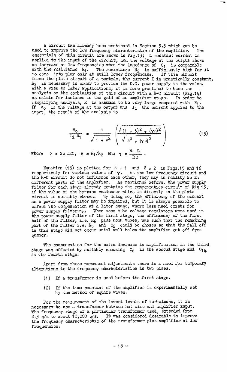
A circiut 1~s already been mentioned in Section 5.3 v;hich can be used to improve the 10~~ frequency character&io of the Nnplifier. ThC essenti&s of this circuit are shown in Fig.13; a constant currant is applied to the input of the circuit, and the voltage at the output shcvn an increase at low frequencies wheH tho impedance of Cl kth the rosistanco RI.
is ccmparablo The rcsistancc R2 is sufficiently high for it
ta corn0 into play only at fitill lower frcquencios. If this circuit forms the plate circuit of a pontcdc, the current I is practically constant. R2 is necessary in order to provide the D.C. power supply to the valve. With a view to later applications, it 1s more practical to base the analysis on the combination of this circuit tith a R-C circuit (hg.14) as exists for instance in the grid of an amplifier stage. In crdcr to simplifying snalysis, R is assumed to be very large ccmparcd with Pr.. If vc is the voltage at the output and I, the current applied to "he input, the result of the analysis is
(15)
RI ol where p = 2% fRC, 6 = Rj/R2 and y = K .
Equation (15) is plotted for S = 1 and 6~2 mFigs.15andl6 respectively for various values of y. As the low frequency circuit and the R-C circuit do not influcncc each other, they mey in reality be in different parts of the amplifier. As mentioned before, the pcwer supply filter for each stage already contain 8 the compensation circuit of Fig.13, if the value of the by-pass ccndenscr which is directly c.n the plate circuat is suitably chosen. By doing so, the efficiency of the circuit as a pcwcr supply filter may bo impaired, but it is akays possible to offect the compensation at a later ma&o, whcrc loss need exists for pcvier supply filtering. Vhen neon tube voltage regulators were used in the power supply filter of the first stage, the effimency of the first half of the filter, i.e. R6 plu 8 noon tubes, %as such that the remaining part of the filter i.e. R5 and C2 could be chosen so that the fall off in this stage did not occur until well bclcvrthe amplifier cut off fre- cp3ncy.
The ccmpensatccn for the extra decrease in amplification in the third stage was effected by suitably choosing C6 in the second stage and C74 in the f,burth stage.
Aprt from these permanent adjustments there is a need fcr tomporEUy alterations to the frequency characteristics in two cases,
(1) If a transformor is used before the,first stage.
(2) If tho time constant of the smplifier is cxperimsntally set by the method of' square waves.
For the measurement of the 1oEest levels of turbulence, it is necessary to use a transformer between hot v&ire and amplifier input. The frequency rango of a particular transformor used, extended from 2.3 c/s to about 10,000 c/s. It vas considered desirable to improve the frequency characteristic of the transformer plus amplifier at low frequencies.
-18-

The usual method of determining the time constant of a hot wire, is by superimposing on the constant heating current of the hot wire, a small alternating current vrith a square wave form. Due to the thermal lag of the hot wire, this wave form is distorted, but it is brought back to its original form by a correct setting of the time constant III the amplifier oomponsation stage. In order to avoid any additional distortions by the amplifier itself, rather stringent conditions hold for the phase shiftll, If a square wave is fed. into the amplifier tith the normal condenser C$b in the fourth stage, it is reproduced pVlth a slight tilt in the horizontal part of the vave form. Although allowance could be modo for this, it is more convenient to e-ate it in the emplif~cr by temporarily altering the oircuit.
For both purposes, i.e. improvement of the low frequency characteristio of the amplifier with transformer input, end rcduotion of phase shift tith a square ~vc input, tho low frequency compensation cirouit in the fourth stage has been used; tho condenser transformer input and by ($5 = 1 FF
C-p is replaced by 013 n.3 pF for or square wave compensation setting.
6.0 Furthor Details of Amplifier
The amplifier is housed in two separate shielded boxes; the first one contains the first three stages, and the second one the remaining stages, Individual stages are shielded from each other by oompartments vrithin the boxes, and the anode cand cathode coils are in separate mu-metal ClUlS, This shielding Yjas sufficient to prevent self oscillation under all operating con&tions but there was an interference between elements of the compensation stage which was notiocd by deviations from tho cal- culated frequency cheraoteristio. This was rmedied by placing the oom- pensation valve itself in a compartment, so that the grid was shielded from cathode and anode.
Interference due to microphony in the valve in the first stage, wa3
effeotivcly remove3 by using a miniature trio& and housing it zn a sealed steel oasmg suspended by rubber bands. A pentode of normal size in the second stage had too much microphony even when using selected valvos. A ndniaturc pentode suspended on rubber bands proved satisfactory, but if a new amplifier is built, it is recommended to house this valve also in a steel box. The third and fourth stages arc not so important, but cvon here, selected normal sizad pontodes wore used. It is probably advisable to use miniat-ure pentodes here too, because their microphony is generally less than that of on&nary siz& valves.
In order to avoid noise being produced by resistances, the 'grid stopper' resistances (R2, Rg, R15 etc) were kept as low as possible (about 600n). As plate resistance of the first valve, a %ire-wound resistor was chosen, in other to avoid the noise from a granular resis- tance when a direct current flows through it.
7 Discussion of Characteristics of Amplifier
Four curves are given for the low frequency characteristics of the amplifier vmthout compensation (Pig.20). One is for the amplifier as originally built lath a drop of 3% at 2.6 c/s. The second shows en mpmvemcnt in the lower frequency lindt from 2.6 c/s to I.4 c/s and the third shows the overall gain of 1 amplifier plus a transf'onncr Nith 25:l amplifioation. In this oaso, the compensating condenser Cl is matched into the fourth stage. The amount of over compensation is t ?l ought to be tolerable. A o-e is also given of amplifier plus transfolmc; without low frequency compensation, i.e. with condenser Cl& in circuit.
- 19 -

The curves of high frequency gtixn lnthout compensation were taken for the whole ampLflcr ("high gaxn" in Fsg.9) and for the emplifxer with first stage by-passed claw gain" xn P'ig.9). In each case, the frequency characteristic was taken for three settings of the potentxmetcr, R.,&; full gain, nuddle of tho potentiometer, snd a setting somewhere near the bottom of the potcntiameter. The first stage cau3cs an extra fall off, and the effeot of potentiometer setting 1s also quite noticeable. A3 the.opcration of the empl1fier 1s restricted by a filter whose highest frequency 1s 50,000 c/s, both effects are consxdered to be tolerable.
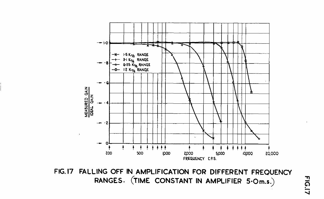
Figs. 17, 18 and 19 show the gain of the smpllfier with compensation, compared with the ideal gain, A, for a particular setting, constant, where
7, of the tune
A = A,Jl + (279” P .* >
AC msnt
is the gain at zero frequency, end f IS the frequency. The agrcc- 1s mthin a f% percent, up to the cut off frequency, accpt m the
case of the low value of time constent (Fig.19). This effect ha3 been explained m Scctlon 6.5 and yias considered to bc tola-&le.
The apparent noise level of the amplifier (see Section 5.2) is shown in F1g.21. Ths qusntlty varies apprcuably v;ith the bend width of the ampl1flcr and with the tlmc constant sottmg. Thus, for the low time constant of 0.2 m.s. and on the ranges lower than 6 Kc/s, the nolso level is less than IO PV. With a time constant of 5 m.s. ar.d 0~1 the 50 Kc/s range, however, the noise level rises to 1600 pV. The input voltage needs to be at least three times the noise level so that the increase in r.m.3. output due to noise shall not exceed 5%. Thus the ltits of input voltage set by the noise level appear to be IO-20 pV snnd 1+.8 m,v. for the two extreme settlngs of time constant and frequency band mentioned before. Disturbances from the power supply do not allow input voltages of less then 100 pV to be measured. With the transformer input, the maxlmum sensltlvity is 4 pV.
Fxg.22 shows that above a certain value, the current througn the thermojunctlon in the output stage cea3es to be proportionalto the empli- fier input. Thxs is due to the svnng mto the non-linear characteristics of the valves, where harmonics of the input frcqucncies arise. The linear range of the output is suffxcient for practical purposes; some non-linear range is unavoidable if the clrcluts are to protect the thermojunotion from ovcrloedmg. In Fig.22 a plot of the galvenometer rcad.mg used in con- junction nth the thcxmojunotlon is also given. About two thirds of the galvanometcr scale 1s wxtLn the linear range of the amplifier.
The question now ar~scs as to whether the specifications for the amplifier, as given in Section 2, have been fulfdled by the present ampliflor. It appears from this section, that this 13 so, as far as frequency range and filter performance are concerned. It should also be mentlonod that solf osmllatlon and microphony of valves were both avoukii. However, for supersonio turbulence work, where a large fre- quency range may be mvvolved, the sensitivity of the present nmpllfier may not be sufficlent,due to the high noise level. The noise level of the first valve, where the majority of the noise originates, can be expressed as an equivalent rnput resistance at the grid of the first valve. This reslstmce is about 3OOOn for the valve Used, ?dlerOas the lowest values arc about 300f12. This mesnns, expressed in input voltages, a reduction to about j/3 of the present value (tho eqmvalent re3istmce is proportionalto the square of the cquivalont input voltages). Several
- 20 -

other valves aerc used in turn in the first stage, and a table of thoir apparent noise levels is glvcn in Flg.23. They were used under the same oonditlons as the miniature triode (C.V.ljg), the valve permanently connected in the first stage, and it can be seen that there was little to be gained by using any of the other valves. The lower values of equivalent resistance can be obtained by using a triode vdth a high trans- conductance, which in turn roqwres a hxgh plate current. As the power supply falter requires a substantial voltage drop over the resistances n-hich it contains, an increase z.n plate current can only be obtained either by a much higher voltage po%ver supply (it need only be for the first stage) or by a reduction of the resistances in the filter. The latter would entail some restriction of the low frequency range. As one vjould expect the low frequency range not to be so important for supersonic turbulence, this seems to be a suitable way out. If the ne& arises, the best solution along these lines would be to build en extra first stage, perhaps \vith its own power supply. Alternatively, a transformer, dcsigxd to Cover tho require3 frequency range, ~0uJ.d give a lowr apparont noise level.
f
A
A,
z
L
R
RP
RB, +3
&l
j
EC3
Ep
w
WO
q
6
E
Y
=
5
LIST OF SYMBOLS
frequency
wire sensitivity at frequency f
mre sensltxvity at zero frequency
tune constant
inductance
resistance
cf. Section 4
cf. Fig.2
mutual conductance (cf. Section 4)
J-1
grid voltage
plate voltago
2xe
l/i‘55
w Wo /

Z
e
U'
F(f)
C
co
E
P
B, b, m
P
6
Y
go&
1
2
3
4
5
6
7
LIST OF SrmOLS (conta)
iJQX!dSJlCC!
voltage acrass hot wire
intensity of vind fl.uctuation
cf. equation (7)
(output voltage)/(input voltage)
c at f = 0
output voltage
2W RC
cf. equation (13)
amplifier output/input
v2 -l
(R, Cl)/(=) '
cf. equation (15)
Author
Mock, Dryden
&huh
Kov&znay
Schubauer, Klebanoff
lbwn.3 end
Schuh, T/inter
Schuh
Title, etc.
I Improved Apparatus for the Measurement of Fluctuations of Air Speed in Turbulent Flow N.A.C.A. Report No. L&8 1932
An Electrical Instrument for tibulence Measurement (m 6607 1944)
Some Improvements in Hot Wire Ancmometry (Hungaria Acta Physica Vo1.I No.3 1946)
Theory and Application of Hot Vire Instruments in the Investigation of Turbulent Boundary Layers (N.A.C.A./TIB/1071 1946) A.C.R. No. 5K27
Measurement of double and triple correlation derivatives in isotropic turbulence. Proc. Camb. Phil. Sot. 43 (560-570) 1947
R.A.E. 4 ft x 3 fti Experunental Low Turbulence Vind Tunnel Part II (R.A.E. Rep. Aero.2285) 6.R.C. 11,829 August, 1948.
Determination of the Sensitivity and Time Constant of Hot Kires for tibulence Measure- ments (Rep. and Transl. No.165 1946) A.R.C. 10,046
- 22 -

&. Author
a Dryden, Kueth
9 Tez¶nan
IO Te-
ll James, Mitchell
12 Spangenberg
REFERlIE% (Contd)
Title, etc.
The Measurement of Fluctuations of Air Speed by the Hot Wire hemometer N.A.C.A. Rep. No.320 1929
Radio Engineers' Handbook 1st edition 1943 page 356 and 357 Published by McGraw-Hill Book Co.
The same, page 414
Turbulence Measuring Apparatus B.&E. Tech. Note Inst.949 ARC. 9885. wch, I 946
Vacuum Tubes :st edition lVI+8 page 327. Published by McGraw-Rill Book Co.
- 23 -

RI :lOKn R2 62On R3 1 ooon R4. 3OKil
:; 33Kn 33Kfl
R7 51 OKfl % 6200 R9 3m RI o 2OKC-I RI1 150Kn RI 2 12KCl
Carbon Wire Wound Carbon Carbon Carbon Carbon Carbon Carbon Garb on Carbon Carbon Carbon Pot 2w Carbon Carbon Carbon Carbon Carbon Carbon Pot 2TV frcquenoy
Renge (see oompn. cu.-. values) Ion 6200
+ IV. Carbon 7 W. Carbon
1500n g W. Carbon I 201cn 1 W. Carbon
1 w.
jj;* I w: I w. 1 w. -+ vi. 3 w. 7; N 1 w: ; w. $ w. z w. Log $ PI. il- w f w : g w. 1 w.
Resxkances -
Carbon R26 Carbon R27
270m 1 OK0 62Irn 1 ooon LO6
R21 Varmble mth
R22 R23 R24 R25
APPYi2DIX I --
Clrcut Values m Fig.1
Condensers
Cl 0.25 CIF 35OV c2 16 IAF 350V C3 16 P 35ov C4 0.25 pF 35ov c5 4PF 35o.v c6 8 G' 35o-J c7 8 pF 35m Ca 0.5 PF 35ov CP 4PF 350n clo ‘3F 35OV cl1 35ov ( c12 Variable mth frequency
rmgo (see oompn. cir. values)
R2R28 R2v R30 R31 R32 R33
2% R36 R37 R38 R3s R4O R41 R42 %3 R44 %5 Q.6 R47
% R50 R51 '52
1 COKD IOKO 51OKn 33oon lOoI IMQ IOKO 47Kn
%-Z 5000n 15Kn 510KR 51 OKfl 1 ooon 47oon
tzon 5oon 390 f-l 22oQn 50000 51 OIin 5ooon 390n 12om 51m
L W. Carbon -? W. Carbon 5: F Vi. Carbon $ W. Carbon G- W. Carbon f W. Carbon f W. Carbon f w. cm-bon -4 W. Carbon 1 W. Carbon 3 w. Carbon 1 W. Carbon 1 W. Carbon f W. Carbon g W. Carbon -$ VT. Carbon T W. Carbon 1 W. Carbon Wire Wound Pot 4 y. Carbon 7 T.f. Cm-born p II. Carbon -q W. Carbon
W. Carbon % W. Carbon 9 W. Carbon 1 W. Carbon
Cl3 31.1F 35ov
2: 12 pF 35w 1 UF 35w
4'6 41.IF 35ov 0.25 I.@ 35m
350-J 35w
c20 0.25 pF 35OV c21 0.25 MB 350V c22 4 0 350V c23 0.25 PF 35~ Cu, 49 35ov '25 4 I-IF 35w
- 24 -
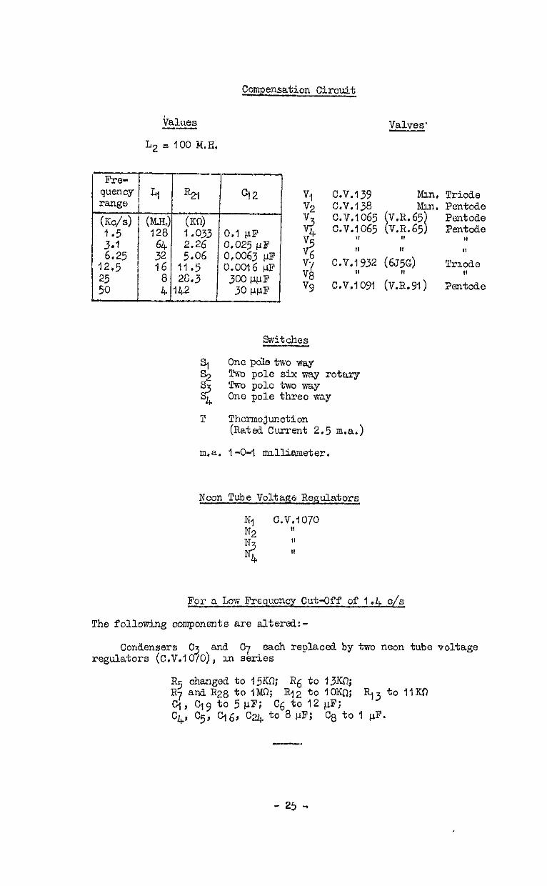
Compensation Circuit
iralues --
L2 = 100 M.H.
Valves'
Mm, Trio&e Mm. Pentado
Sxitchea
s, One pole two way S2 %o pole six xay rotary
f$ TKO pole txc w3.y One pole threo way
T Thcrmojunction (Rated Current 2.5 m-a.)
m.a. I-O-I mxlliameter.
Noon Tube Voltage Regulators
For a LOY; Frequency Cut-Off of I.& o/s
The following components are altered:-
Condensers C regulators ?
and c-f (C,V.lO 0),
each replaced by two neon tube voltage 3.n series
R5 changed to 15Kn; R6 to 13Kn; R7 and R28 to I?@; R12 to IOlin; R.,3 to llw) Cj, Cjv to 5@; '26 to 12 I.rF; C4, C5, q6, Cu, to a PF; Ca to I pp.
- 25 -

APP-mDIxII
Apparent Noiss Level of Varmuss Valves as first Stage of Aaplif3er
Valvo 3.1 Kc/'s 6.25 Kc/s 12.5 XC/S 25 KC/S 50 KC/S Range Range Rango. Range R=%c
c.v.139 (Min. Tnode) 4.9 pv 14.5 ccv 4Q w 109 I-IV 290 PV
C.V.138 as Trlodc 5.6 w 14iJv 38PV 97 PV 25o!Jv
A.C.100 Trio& 7 PV 17 PV 42 NJ 100 pv 250 PV
62J7 Trio& 22 pv 47 N 111 pv 270 PV
v.R.56 as Tridc 13.2 pv 40 WV 97 Pi 245 PV
- 26 -
Wt.2078.CP.188.K3 - Printed In Oreat Brstaln.


i.
I I
I VC V8 Q I + 280 Y ------------------ -------
;
FIG. I! , CIRCUIT DIAGRAM OF AMPLIFIER FOR 2.6 ‘/s TO 50,000 ‘/s

FIG. 2&4@ab)
4P
E P
FIG.2 SIMPLIFIED COMPENSATION STAGE.
L “t R
R r 0 0 COMPENSATION (b> COMPENSATION
‘IN” *OFF”
FIG.4(asb) COMPENSATION SWITCHING
ARRANGEMENT.

*5- /
-0 - l-9 -
keg-
)*7 -
IG-
xl -
Kl -
PHASE ANGLE
I.2 - LAG FROM I DEAL COMPENSATION
FIG. 3 CALCULATED FREQUENCY CHARACTERISTIC OF COMPENSATION CIRCUIT. &

FIG.56 8 7
R R
INPUT c =z c == OUTPUT
0 0
FIG.5 TWO STAGE R-C FILTER.
Rp,
~
t- C
R
I--- C
R
POWER
SUPPLY
FIG.6 POSITION OF FILTER IN IS1 STAGE.
FIG.7 SUBSTITUTE DIAGRAM FOR R-C COUPLING IN AMPLIFIER .

FIG. 8
- DO2
- o-01 .
--0005 -
ccl 72
z 0 -0-002 5
FIG. 8 FREQUENCY CHARACTERISTIC FOR z
ATTENUATION OF DISTURBANCES FROM
A POWER SUPPLY (SEE s~c.5.3)’

FIG. 9
.
- -9 LOW GAIN, FULL POTENTIOMETER LOW CAIN, BOT70M OF WlEHnOMET
s LOW GAIN, MIDDLE OF iUlENT!OMElE
-a8 HIGH @IN, FULL FOTENTIOMETE
8 HIGH GAIN, MIDDLE OF PDTENflCMETE 0 2 LOW GAIN : FIRST STAGE BY-PASSED z z-*7
\ z s
.
*. 6
1 I t t t ttttt t 1000 2000 4000 woo ema lop0 20,OW
fQd t ttttt @PJ w 'mpoo
FREQUENCY C/S
FIG.9 FREQUENCY CHARACTERISTIC OF ;
UNCOMPENSATED AMPLIFIER AT HIGH l
FREQUENCIES

FIG.IO& II
VALVE I r II
RK
RP
RP F
RC = RK -
RP =
m=
500 Kn
loo n
20 K ri
80-100
VALVE II II
FIG.10 PHASE CONVERTER STAGE ORIGINALLY USED.
VALVE I
R8
RP
1 q 2
0 OUTPUT
‘c--Q eaov
RP
I 1 VALVE n
N-J
RK. 100 .I\
Rs = IMrL
mm a0 -100
RP = ZOKJI,
FIG.11 PHASE CONVERTER STAGE FINALLY
USED.

FlG. I2.l3& 14
FIG. 12 AN AMPLIFIER STAGE WITH POWER
SUPPLY FILTER AND R-C COUPLING.
INPUT f
RI OUTPUT
FIG.13 LOW FREQUENCY COMPENSATING
CIRCUIT
vo
FIG.14 LOW FREQUENCY COMPENSATING
CIRCUIT PLUS R-C COUPLING.

Ii RI
~ 0.1 0.2 0.5 I.0 S.&f 5 IO 20 50 100
RC 3
FIG. 15 FREQUENCY CHARACTERISTIC OF CIRCUIT OF FIG. I4 . P G

.!k Ii RI
I I
‘6
I I IIIIIII -
P-2ITfRC
FIG. 16 FREQUENCY CHARACTERISTIC OF CIRCUIT OF FIG.14
-t t t t ttttt t t t t+t+tt t 200 500 wo woo 5poo qooo 20,000
FREQUENCY C P.S.
FIG.17 FALLING OFF IN AMPLIFICATION FOR DIFFERENT FREQUENCY RANGES. (TIME CONSTANT IN AMPLIFIER 500m.s.)

I \ \I
-a+ i-5 KyS RANGE -t- 5.1 Ky, RAN@ I\ \
@25 KS RANGE \ \ I 2 K y, RANGE
2SKy, RANGE SOKc/, RANGE \
\
‘2 \I
\\
\ I
c \< 1 IX
Ot
1
k t t tttttt t t t tttttt t t t tttttt 100 200 500 1000 2000 5000 lqo00 24000 5qocQ IOQOOO
FREQUENCY C RS.
FIG.18 FALLING OFF IN AMPLIFICATION FOR DIFFERENT FREQUENCY RANGES.
(TIME CONSTANT IN AMPLIFIER I-0 m.s)

100 zoo 500 1000 2000 5000 IQ000 ZQOOO 50,000 100,000 FREQUENCY C.P. 5.
FIG.19 FALLING OFF IN AMPLIFICATION FOR DIFFERENT FREQUENCY RANGES (TIME CONSTANT IN AMPLIFIER O-2 m-s.)
x 9 z

FIG. 20
I*4y, CUT OFF PLLIS COMPENSATE
TRANSFORMER INPUT 1*4y, CUT OFF pws f.uOwm@
TWNSFORMER INPUT
I i 4 6 8 IO 20 30 FREQJENCY Cls
FIG.20 LOW FREQUENCY CHARACTERISTICS
OF AMPLIFIER.
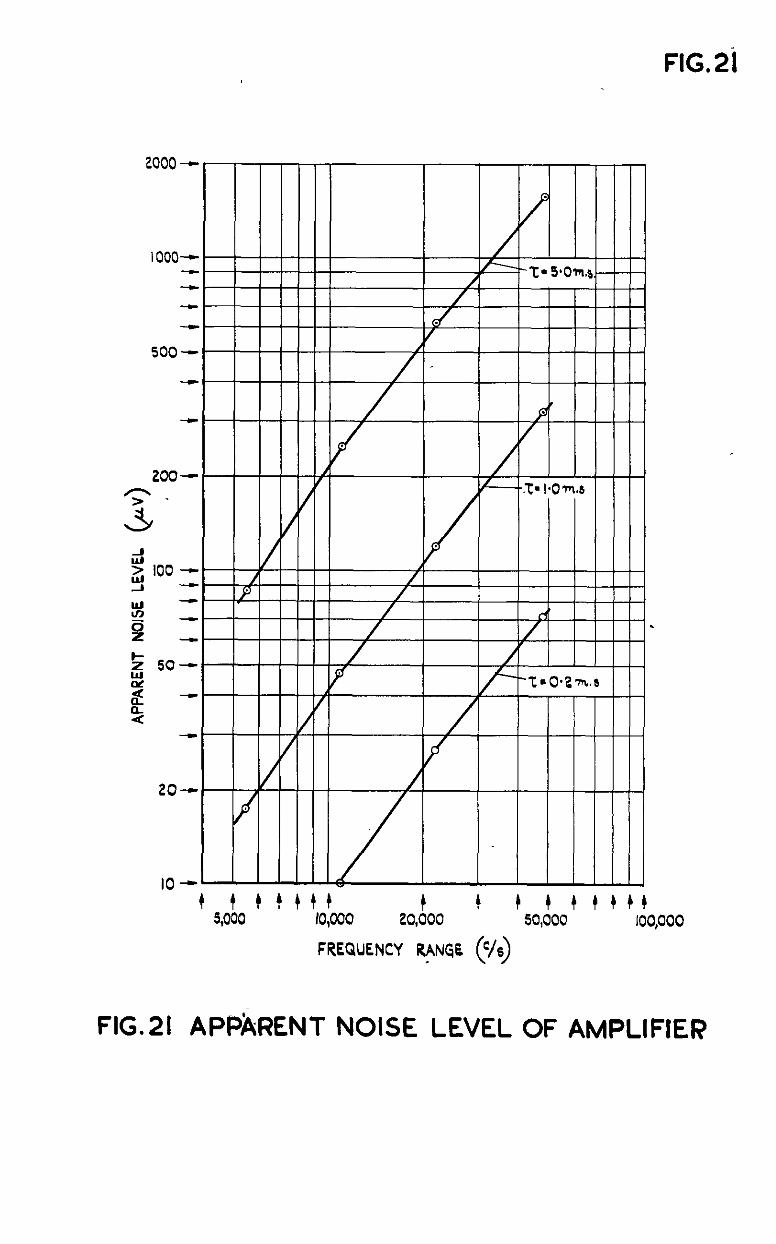
FIG. 2i
+ 5,olo + ’ ’ +,o+ooo t t FREcil”ENc~o’;L (c/s)
tso!oot t + c t t roo,ooo
FIG.21 APPkRENT NOISE LEVEL OF AMPLIFIER

FIG 22
-
0 “i” ,
AMPLIFIER INPUT VOLTAGE @R~ITRARY)
FIG.22 AMPLITUDE DISTORTION OF AMPLIFIER.


C.P. No. 198 (16.272)
A.R.C. Technlcal Report
Crown Copyrrght Reserved
York House, Kmgsway. LONWN, w c 2 : 423 Oxford Street, LONDON, w.1 P 0 Box 569, LONDON, s e.1
13a castle stnet. BDMB”RGH, 2 1 St. Andrew’s Crescent, CMWIPP 39 Km8 street, MANc-, 2 Tower lane. BRLPIUL, 1
2 Edmund Street, BIRMMOHAM, 3 80 Chxhester Street. BELFAST or from any Bookseller
1955
Price 4s. Od. net PRlNTED IN GREAT BRlTAlN
S.O. Cede No. 23-9037-98
C.P. No. 198