wide range displacement expressions for … · all of the specimens that appear in astm standard...
TRANSCRIPT

ADrA HL s^Q> TECHNICAU LIBRARY
AP^^yy,^ 3-6^
TECHNICAL REPORT ARLCB-TR-84025
WIDE RANGE DISPLACEMENT EXPRESSIONS FOR
STANDARD FRACTURE MECHANICS SPECIMENS
J. A. KAPP
G. S. LEGER
BERNARD GROSS
JULY 1984
US ARMY ARMAMENT RESEARCH AND DEVELOPMENT CENTER LARGE CALIBER WEAPON SYSTEMS LABORATORY
BENET WEAPONS LABORATORY VVATtRVLIET N.Y. 12189
APPROVED FOR PUBLIC RELEASE; DISTRIBUTION UNLIMITED

DISCLAIMEa
The findings In this report are not to be construed as an official
Department of the Amy position unless so designated by other author^
ized documents.
The use of trade nanie(s) and/or manufacture(s) does not consti-
tute an official indorsement or approval.
DISPOSITION
Destrcy this report when it is no longer needed. Do not return it
to the originator.

SECURITY CLASSIFICATION OF THIS PAGE (When Data Entered)
REPORT DOCUMENTATION PAGE READ INSTRUCTIONS BEFORE COMPLETING FORM
1. REPORT NUMBER
ARLCB-TR-84025
2. GOVT ACCESSION NO, 3. RECIPIENT'S CATALOG NUMBER
4. T\ri.E (and Subtitle)
WIDE RANGE DISPLACEMENT EXPRESSIONS FOR STANDARD FRACTURE MECHANICS SPECIMENS
5. TYPE OF REPORT & PERIOD COVERED
Final 6. PERFORMING ORG. REPORT NUMBER
7. AUTHORfsJ
J. A. Kapp, G. S. Leger, and Bernard Gross (CONT'D ON REVERSE)
8. CONTRACT OR GRANT NUMBERfs;
9. PERFORMING ORGANIZATION NAME AND ADDRESS
US Army Armament Research & Development Center Benet Weapons Laboratory, DRSMC-LCB-TL Watervllet, NY 12189
10. PROGRAM ELEMENT, PROJECT, TASK AREA a WORK UNIT NUMBERS
AMCMS No. 6111.02.H600.011 PRON No. 1A325B541A1A
11. CONTROLLING OFFICE NAME AND ADDRESS
US Army Armament Research & Development Center Large Caliber Weapon Systems Laboratory Dover, NJ 07801
12. REPORT DATE
July 1984 '3. NUMBER OF PAGES
25 14. MONITORING AGENCY NAME & ^DDRESS(II dlltereni from Controlling Olllce) 15. SECURITY CLASS, (of thla report)
UNCLASSIFIED
15a. DECLASSIFI CATION/DOWN GRADING SCHEDULE
16. DISTRIBUTION ST^JEMENT (of thla Report)
Approved for public release; distribution unlimited.
17. DISTRIBUTION STATEMENT (of the abstract entered In Block 20, If different from Report)
18. SUPPLEMENTARY NOTES
Presented at Sixteenth National Symposium on Fracture Mechanics, Columbus, Ohio, 15-18 August 1983. Published in proceedings of the symposium.
19. KEY WORDS (Continue on reverse aide if neceeaary and Identify by block number)
Fracture Mechanics Testing Methods Specimen Characterization
20. ABSTRACT fCozrffnue oa rwverma sfoto ff rtacea&ary and Identify by block number)
Wide range algebraic expressions for the displacement of cracked fracture mechanics specimens are developed. For each specimen two equations are given: one for the displacement as a function of crack length and the other for crack length as a function of displacement. All of the specimens that appear in ASTM Standard E-399 are represented in addition to the crack mouth displacement for a pure bending specimen. For the compact tension sample and the disk-shaped
(CONT'D ON REVERSE)
E>D FORM \ JAN 73 1473 EDrTlOM OF » MOV 65 IS OBSOLETE UNCLASSIFIED
SECURITY CLASSIFfCATIOK OF THIS PAGE (When Data Entered)

SECURITY CLASSIFICATION OF THIS PAGECHTian Data Entend)
7. AUTHORS (CONT'D)
G. S. Leger Graduate Student Mechanical Department University of New Mexico Albuquerque, NM 87106
Bernard Gross Materials Engineer NASA-Lewis Research Center Cleveland, OH 44135
20. ABSTRACT (CONT'D)
compact tension sample, the displacement at the crack mouth and at the load line are both considered. Only the crack mouth displacements for the arc-shaped tension samples are presented. The agreement between the displacements or crack lengths predicted by the various equations and the corresponding numerical data from which they were developed are nominally about three percent or better. These expressions should be useful in all types of fracture testing including J-];^, %, and fatigue crack growth.
SECURITY CLASSIFICATION OF THIS PAGEfWTien Data Entered)

TABLE OF CONTENTS
INTRODUCTION
PROCEDURE TO DEVELOP NONDIMENSIONAL DISPLACEMENTS
RESULTS AND DISCUSSION
Bending Samples
Pin-Loaded Specimens
Arc-Shaped Tension Specimens
CONCLUSIONS
REFERENCES
Page
1
1,
■ I:
6
9
12
14
15
TABLES
I. CRACK. NOTCH OPENING DISPLACEMENTS FOR PURE BENDING SAMPLE
II. CRACK MOUTH OPENING DISPLACEMENTS FOR THREE-POINT BEND SPECIMENS
III. LOAD LINE DEFLECTION OF THREE-POINT BEND SAMPLES
IV. DISPLACEMENT FOR COMPACT TENSION SAMPLES AND DISK- SHAPED TENSION SAt^lPLES
V. CRACK LENGTH AS A FUNCTION OF DISPLACEMENTS FOR COMPACT SAMPLES
VI. CRACK MOUTH DISPLACEMENTS AS A FUNCTION OF CRACK LENGTH FOR ARC TENSION SAMPLES
VII. CRACK LENGTHS AS A FUNCTION OF CRACK MOUTH DISPLACEMENTS FOR ARC TENSION SAMPLES
16
17
18
19
20
21
22
LIST OF ILLUSTRATIONS
1. A general two-dimensional cracked body.
2. The specimens for which displacement expressions were generated.
23
24

INTRODUCTION
In order to determiae the many fracture properties available to
characterize materials, several parameters of the specimens used must be
known. Foremost among these parameters is the crack length. Measuring
properties such as J-reslstance curves, K-resistance curves, and fatigue crack
growth rates, the crack length changes must be measured during the actual ' ,
test. Several techniques have been devised to measure crack growth by
Instrumenting the sample. Perhaps the simplest method is the so-called
"compliance" technique where the elastic compliance of the specimen is
measured by simultaneously measuring the load and displacement of the sample.
Since the elastic load-displacement characteristics of any cracked body are a
function of the elastic properties of the material tested and specimen
parameters including crack length, the elastic properties or the crack length
for any sample can be determined If the other is known.
Presented in this report are algebraic equations that allow for the easy
calculation of either crack length or elastic properties for many standardized
specimens.
In order to determine the elastic properties of the material from which
the specimen was laade, an expression which gives the load-displacement
characteristics as a function of crack length must be developed. Similarly,
to calculate the crack length, an expression must be developed where the crack
length Is a function of the load and displacement measured. Expressions of
both types were developed for all tVie standardized specimens in ASTM E-399 and
for a rectangular pure bending sample.
-'+!i

The expressions are developed by first establishing the appropriate
limiting displacements as the crack approaches zero length and as the
remaining ligament approaches zero. This is accomplished using the Paris
equation (ref 1) based on Castigliano's theorem. These limiting solutions
serve as guides when choosing a nondlmenslonal form of the specimen
displacements which has finite limits at short and long crack lengths.
Numerically determined displacements are then normalized to the nondlmenslonal
form derived from the limiting solutions, and multlvariable regression is used
to fit a polynomial to these data. The resulting algebraic equations
represent the displacement solutions nominally within three percent over a
wide range of specimen parameters.
PROCEDURE TO DEVELOP t^ONDlMENSIONAL DISPLACEMENTS
To determine an appropriate nondlmenslonal form of displacements for the
various specimens considered, Paris's application of Castigliano's theorem to
crack problems (ref 1) was used. For the general two-dimensional cracked body
shown in Figure 1, the displacement due at the location at the applied force F
in the direction of F Is:
2 a 3Kp 6„ = — / K_ da (1) * E' ap P aF
where Kp is the stress Intensity factor due to the force P, Kp is the stress
intensity factor due to the force F, and E' Is Young's Modulus (E) for plane
stress or E/(l-\>^) (v = Poisson's ratio) for plane strain.
^Tada, H., Paris, P., and Irwln, G., The Stress Analysis of Cracks Handbook, Del Research Corp., Hellertown, PA, 1973.
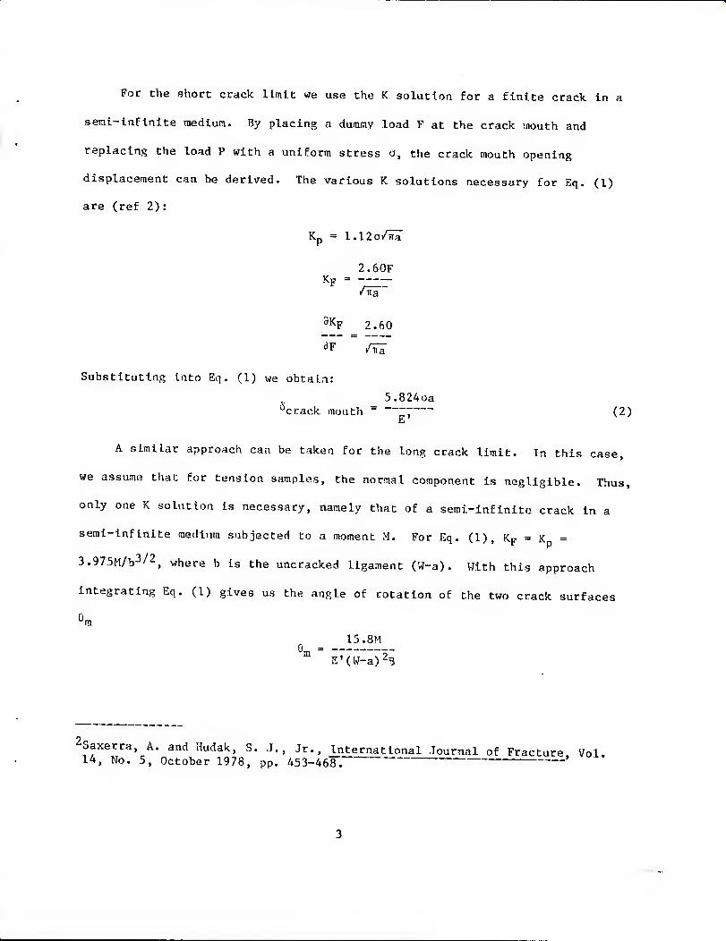
For the short crack limit we use the K solution for a finite crack. In a
seml-lnflnlte medium. By placing a dummy load F at the crack mouth and
replacing the load P with a uniform stress o, the crack mouth opening
displacement can be derived. The various K solutions necessary for Eq. (1)
are (ref 2):
Kp = 1.12a/il
2.50F Kp = -----
MTa
^% 2.60
Substituting into Eq. (1) wa obtain:
5.824aa '•'crack mouth ~ ~7 (2)
A similar approach can be taken for the long crack limit. In this case,
we assume that for tension samples, the normal component is negligible. Thus,
only one K solution is necessary, namely that of a serai-infinite crack in a
semi-Infinite medium subjected to a moment M. For Eq. (1), Kp = x =
3.975M/b3/2, where b is the uncracked ligament (W-a). With this approach
Integrating Eq. (1) gives us the angle of rotation of the two crack surfaces
K 15.8M
'm
E'(W-a)^B ■^ T7I/,.,_„N2.
-Saxerra, A. and Hudak, S. J., Jr., International Journal of Fracture Vol. 14, No. 5, October 1978, pp. 453-468.' -'

where 3 is the out-of-plane thickness of the specimen. The crack mouth
displacement Is estimated as the arc length swept out by Qj^ at the distance W,
or
15.8 HW
E'(W-a)^B "crack mouth ,77" ^~2r- '
Using Kqs. (1) and (2) xve can derive the appropriate nondimenstonal form
of displacement based on the loading conditions and specimen parameters of the
Individual samples being considered. This enables us to fit an expression to
the available data that gives the displacement as a function of crack length.
Manipulating these equations will result in a mathematical form of displace-
ments which is a function of crack length alone and has finite limits as the
normalised crack length (a/W) approaches both :^ero and one.
Developing an expression to calculate the crack length as a function of
measured dis.nlacements is not as straightforward as the above procedure. A
first approach would be to solve for crack length In either Eq. (2) or Eq. (3)
and use this as a aondiiuensional for/n of displacement. For example, Eq. (3)
can be written as: 1/2
a 15.3M '■■ - = 1 - (----:) (4)
which applies as 6 > "°, but when 5 goes to zero, Eq. (4) predicts a crack
length of negative infinity when it should give a value of zero. Equation (4)
can serve as guidance in selecting a form of nondiraensional displacement with
reasonable limits that can be used to accurately calculate crack length. We
assume that:
^ = f(5') (5)

6- = (6)
1 + ( -) E'BWfi
It is clear that as the displacement goes to zero, 5' also goes to zero
and as 6 goes to infinity, 6' goes to one. These limits enable the function
f(6') to be fit to the numerical data with great accuracy. A form of
displacement similar to Eq. (6), has been suggested (ref 2) for a compact
specimen.
Some variation of Eqs. (2), (3), and (6) is necessary when finding
expressions for the load line displacements of the three-point bend sample and
for the arc tension sample. But the resulting nondlmensional form of
displacements is only subtly different from the above.
RESULTS MD DISCaSSEON
All of the specimens studied are shown in Figure 2. Three cases for the
bending sample are presented: crack mouth opening displacement under pure
bending, crack mouth opening displacement, and load line deflection under
three-point bending. The three tension samples considered were the compact
tension, the disk-shaped compact tension, and the arc-shaped tension samples.
Expressions are presented for the load line displacement and the crack mouth
opening displacement for all the tension samples except the arc-shaped sample.
Only crack mouth opening was considered for this sample.
^Saxerra, A. and Hudak, S. J., Jr., International Journal of Fracture, Vol. 14, No. 5, October 1978, pp. 453-468.

Bending Samples
For the crack mouth opening displacement under pare bending, the short
and long crack limits using Eqs. (2) and (3) are:
11m E'BW6 = 2.212 (7)
a/W > 0 15.8M(a/W)
lira E'BW5(l-a/W)2 =1 (8)
a/W ^ 1 15.8M
Thus, we can represent the variation in displacements with (a/W) as
S'BW6(l-a/W)2 "Tr«M;"7m" ^ fPBCM(a/W) (9) 15 .8M(a/W)
Normalizing the numerical data for this sample (ref 3) according to Eq.
(9), fpRCM ^^^ found to be:
fpBCM(a/W) = 2.212 - 4.78 a/W + 7.37 (a/W) ^ + 0.0830 (a/W)'^
- 10.4 (a/W)'* + 5.53 (a/W)^ (10)
Representing a/W as a function of displacements, we used the following:
1 5- = (3^1)
1/2 15.8M '^ 1 + (--—)
E'BW6
a/W = f PBCK('5') (12)
Equation (12) has the limits of zero as a/W approaches zero and one as
a/W goes to one. Again, normalizing the numerical data f'pBCM can be
developed as
f'PBCM('5') = -0-986' + 5.1506-2 - 4.286'3l.116'^ (13)
Gross, B., Roberts, E., Jr., and Srawley, J. E., International Journal of Fracture Mechanics, Vol. 4, 1968, p. 267.
6

The accuracy of Eqs. (10) and (13) is demoastrated by the comparison
shown in Table I. In Eq. (10) the displacement can be represented within
± 1.5% for all a/W ratios, and the crack length can also be predicted within
± 0.7% W for any displacement from Eq. (13).
For the crack mouth opening displacement of the three-point bend sample,
the short and long crack limits are essentially the same as Eqs. (7) and (8).
The value of the moment is replaced by PS/4, thus these limits are
1 im E B o /1 / \ =2.212 (14)
a/W ^ 0 3.95P(S/W)(a/W)
lim ^^[^^^I'tl^ill = 1 (15) a/W ^ 0 3.95P(S/W)
The nondimensional form of displacement for fitting is then
E'B6(l-a/W)^ , ,' ,,, " 1 = f3PBCri(a/W) (16) 3.95P(S/W)(a/W)
f3P3CM(a/W) = 2.21 - 6.57 a/W + 17.9(a/W)^ -
26.6(a/W)^ + 19.9(a/W)'* - 5.86(a/W)^ (17)
To predict the crack length from displacement measurements, the same form
as above was utilized:
5, = i (18) 1/2
3.95P(S/W) ' 1 + ( )
/ E'B5
a/W = f'3PBCM(^')
f3PBCM(^') = -l-Oa^' + 6.006-2 _ 6.375'3 + 2.736''* - 0.3216'5 (^g)

Comparing Eqs. (17) and (19) with the numerical data (ref 3) in Table II
shows again that the regression equations fit the data within ±3.4%.
The load line deflection of the three-point bend sample requires more
algebra than the two cases already presented. With no crack present, the beam
will deflect due to the applied load. Thus the total deflection is the
deflection with no crack plus the additional deflection caused by the
introduction of the crack. The limiting solutions for the total deflection
^tot then are: lira P(S/W)^ 8.891P(S/W)2(a/W)'^
,5 = f (^0) a/W ^0 '^°'^ 4E'B E'B
lim P(S/W)^ 0.9875P(S/W) ;^^^ = + -5- (21)
a/W > 1 4E'B e'B(l-a/W)^
Fitting the numerical data we used the following form of nondimensional
deflection: EB^tot (S/W) (a/W)2 = + -—- f3PBLL(a/W) (22) P(S/W)'^ 4 (1-a/W)^-
f3PBLL(a/W) = 3.89 - 33.9 a/W + 68.5(a/W)^- - 68.1(a/W)3 + 25,6(a/W)'* (23)
Of the total displacement, the form used was
S. = 1 (24)
, .9875 ,^/2
E'B6tot S/W
P(s7w)2 4
(a/W) = f3PBLL(*') (25)
f 3PBLL('5') = 0.0997 - 0.5166' + 2.856'2 - 1.435'^ (26)
^Gross, B., Roberts, E., Jr., and Srawley, J. E., International Journal of Fracture Mechanics, Vol. 4, 1968, p. 267.

Table III compares the numerically determined load line displacements
(ref 1) with Eqs. (23) and (26) for the case when S/W = 4. As the table
indicates, the displacement as a function of a/W is accurate within ± 1.7% for
any a/W and the crack length can be predicted from displacements within about
± 0.4% for a/W > 0.2.
Pin-Loaded Specimens
Fitting expressions for the displacement of pin-loaded specimens is
somewhat more difficult than with bending samples. We are unable to use the
short crack limit because that requires knowledge of the short crack K
solution. In the compact tension and disk-shaped compact tension configura-
tions, Interactions with the pin loading holes must be considered when the
relative crack length Is less than about 0.2. Although the loading holes are
not a factor with the arc-shaped tension, the value of the radius ratio
{T2/VI) strongly affects K for that sample at short crack depths. We will
concern ourselves only with tlie displacement characteristics for tension
samples when a/W is greater than 0.2. Thus, only the deep crack limit is
considered. For both the compact tension and the disk-shaped compact tension,
Eq. (3) becomes
llm 15.8P 6 = -—- (27)
a/W ■>■ 1 E'B(l-a/W)'^
This suggests that an appropriate nondimenslonal form of displacement for
the compact specimen Is
E'B6(l-a/W)^ 1 = f(a/w) (28)
15.8P
It should be noted that Eq. (27) applies only for load line displace-
ments. Remember that Eq. (3) was derived from the rotation of the crack
^Tada, H., Paris, P., and Irwln, G., The Stress Analysis of Cracks Handbook, Del Research Corp., Hellertown, PA, 1973.

surfaces Oj^j, and tVie displacement was estimated as the arc length at a
distance W from the uncracked ligament. At the crack mouth, the displacement
would be the arc length approximated by 0^ x (W+A), where A Is the distance
from the load line to the crack mouth. Using this formulation would result In
a rather messy equation. For this reason we chose to use Eq. (28) as the non-
dimensional form of displacements and restrict the applicability of the
resulting expression to values of (a/W) less than 0.8.
Four polynomials were found using Eq. (28): load line displacements for
both specimen types and crack mouth displacements for both specimens. They
are:
Compact Tension - Load Line:
fCTLL(a/W) = 0-121 + l.21(a/W) - 0.159(a/W)^ - 1.47(a/W)-- + 1.30(a/W)'' (29)
Disk-Shaped Tension - Load Line: .
fr)XLl(a/W) "■= 0.104 + l.ll(a/W) - 0.262(a/W) •' + 0.0247(a/W)-^ (30)
+ 0.0223(a/W)''
Compact Tension - Crack Mouth:
fCTGM(a/W) = 0.631 + 0.178(a/W) + 1.96(a/W)2 - 3.99(a/W)-'' + 2.48(a/W)'* (31)
Disk-Shaped Tension - Crack Mouth:
fOTCM = 0-595 - 0.168(a/W) + 2.86(a/W)^ - 3.10(a/W)-^ + 1.26(a/W)'* (32)
Comparisons between the numerical data for compact tension samples (refs
3,4) and Eqs. (29) and (31), and the data for disk-shaped compact tension
•^Gross, B., Roberts, E., Jr., and Srawley, J. E., International Journal of Fracture Mechanics, Vol. 4, 1968, p. 267.
^Newman, J. C, Jr., "Stress-Intensity Factors and Crack-Opening Displacements For Round Compact Specimens," NASA TM 80174, National Aeronautics and Space Administration, Langley Research Center, Hampton, VA, 1979.
10

samples (ref 4) and Eqs. (30) aad (32) are shown In Table IV. The following
accuracy statements can be made based on these comparisons. For compact
tension load line displacements ±0.2% for 0.2 < a/W < 0.8; for compact tension
crack mouth displacements t 0.2% for 0.2 < a/W < 0.8; for disk-shaped compact
tension load line displacements ± 0.3% for 0.2 < a/W < 0.8; and for disk-
shaped compact tension crack mouth displacements ± 0.2% for 0.2 < a/W < 0.8.
To determine crack length as a function of displacements, we used the
following variation of Eq. (6):
5. = 1 (33) 15.8P ^^^
1 + ( --) EB6
(a/W) = f(5') (34)
Again, four polynomials were generated for the two samples each with two
displacement measuring locations. These equations are:
Compact Tension-Load Line:
a/W = -0.228 - 0.2526' + 4.606'^ - 4.416'3 + 1.295''+ (35)
Disk-Shaped Tension-Load Line:
a/W = 0.0896 - 1.816' + 7.616'2 - 7.196''^ + 2.306''^ (36)
Compact Tension-Crack Mouth:
a/W = -1.052 + 1.385' + 4.715'^ - 6.415'3 + 2.365''+ (37)
Disk-Shaped Tension-Crack Mouth:
a/W = -1.292 + 3.555' - 0.5896'2 _ 1.646.3 + o.9935'^ (38)
^Newman, J. C, Jr., "Stress-Intensity Factors and Crack-Opening Displacements For Round Compact Specimens," NASA TM 80174, National Aeronautics and Space Administration, Langley Research Center, Hampton, VA, 1979.
11

Table V gives the comparison between the numerical data for these two
specimens (refs 3,4) and the a/W values predicted by Eqs. (35) through (38).
From the table, it can be concluded that the statistical data Elts have the
following accuracies: compact tension-load line ± 0.3% for a/W > 0.2; disk-
shaped tension-load line t 0.1% for a/W > 0.2; compact tension-crack mouth
t 0.1% for 0.2 < a/W < 1.0; disk-shaped tension-crack mouth ± 0.2% for 0.2 <
a/W < 1.0.
Arc-Shaped Tension Specimens
Because of the many different geometries available for the arc-shaped
samples, the wide range expressions are somewhat more complicated. Again, we
are not able to use the short crack limit but not because of loading hole
Interactions, rather because of the curvature at the inner radius. The stress
at the inside radius is necessary to apply Eq. (2), which requires the curved
beam theory. The resulting nondimensional form of displacement is very
complex. Thus, the effects of the eccentric loading (the X/W dependence) and
the effects of radius ratio, r-i^/r2 must also be accounted for. The long crack
limit, Eq. (3) can be used and In terms of arc-shaped parameters we have:
lim E'B5(l-a/W)2 1 1- = 7.9 (39)
a/W ^ 1 (2X/W+l+a/W)
This nondimensional form of displacement accounts for the X/W dependence
for crack mouth displacements very nicely, but we still needed to account for
^Gross, B., Roberts, E., Jr., and Srawley, J. E., International Journal of Fracture Mechanics, Vol. 4, 1968, p. 267. ^Newman, J." C.~, Jr., "Stress-Intensity Factors and Crack-Opening Displacements For Round Compact Specimens," NASA TM 80174, National Aeronautics and Space Administration, Langley Research Center, Hampton, VA, 1979.
12

the rilr-y effects by some other means. Without the short crack limit,
empirical techniques were necessary. Using Eq. (39) to normalize the
available data generated for this report revealed that corrections for the
r-i^/r2 effect of no more than about ten percent were necessary. These
corrections are expressed in the following manner:
E'B6 2X/W+l+a/W = - f^,j,(,^ (a/W, ri/r2) P (l-a/W)-^
fATCM(a/W.^l/^2) = ^-^^ + ^"^-^5 a/W - 12.67(a/W)^- + 6.47(a/W)3 +
+ (l-a/W)0-'35(l-ri/r2)(0.8-0.5 ri/r2) (^0)
(\ comparison of the numerically generated displacements and Eq. (40) is
given in Table IV. The accuracy of the above expression can be stated as: for
K/W = 0 and 0.4 ^ ri/r2 < 0.91, t 2.9% for 0.2 < a/W < 0.8, and i 0.4% for
0.4 < a/W =i 0.5; for X/W = 0.5 and 0.4 < ri/r2 *^ 0.91, ± 3.6% for 0.2 < a/W <
0.8, and t 1.5% for 0.4 < a/W ^0.6.
For crack length as a function of displacement, we use a modification of
Eq. (6):
5. = 1 (41)
,7.9(2X/W + 1)P .-""^^
E'BC
This representation does not account for all of the X/W dependence or any
of the ri^/r2 effects. Again resorting to empirical methods, we can account
for these effects by modifying Eq. (41) as:
fi. = h 0.4 X/W + 0.016 + 0.017 ri/r2 (42)
,7.9(2X/W + 1)P y^ 1 +
E'S6
13

Using this fonn, tVie crack length can be expressed by:
a/W = -0.941o'+ 4.2536'2 - 3.4605'3 + 1.1466''+ (43)
where 6' is calculated by Eq. (42).
Table VII cotupares Eq. (43) with the expected values of crack length.
The errors as a percentage of W can be expressed as: for X/W = 0 and 0.4 <
ri/r2 < 0.91, ± 1.2% for 0.2 < a/W < 0.8, and +- 0.6% for 0.4 < a/W < 0.6; for
X/W = 0.5 and 0.4 < ri/r2 ^ 0.9, ± 1.9% for 0.2 < a/W < 0.8 and ± 0.6% for
0.4 < a/W "i 0.6.
CONCLUSIONS
Wide range displacement expressions for tnany standard fracture testing
specimens were generated by using limiting solutions to develop the proper
nondimensLonal form. These expressions can be used to determine displacements
when a/W is known or to determine crack length when the displacement and '
elastic properties of the specimen are known. These expressions iiay be useful
when using the "compliance" method as a passive means of monitoring crack
growth during fracture mechanics tests.
14
REFERENCES
1. Tada, H. , Paris, P., and Irwin, G., The^_Str^ss_Analy;sl^s__of__^
Handbook, Del Research Corp., HelLertown, P/^, 1973.
2. Saxerra, A. and Hudak, S. J., Jr., International Journal of Fractur^, Vol.
14, No. 5, October 1978, pp. 453-468.
3. Gross, B., Roberts, E., Jr., and Srawley, J. E., int_e£nationalJojiXnal^.^^^
Fracture jlechanlcs_. Vol. 4, 1968, p. 267.
4. Newman, J. C, Jr., "Stress-Intensity Factors and Crack-Openiag
Displacements For Round Compact Specimens," NASA TM 80174, National
Aeronautics and Space Administration, Langley Research Center, Hampton,
VA, 1979.
15

TABLE I. CRACK MOUTH OPENING DISPLACEMENTS TOR PURE BENDING SAMPLE
a/W
fpBCM (reE 3)
fpBCM (Eq. 10)
Error (%)
0__
2.212
2.212
.2
1.530
1.537
+0.5
.3
1.390
1.375
-1.1
1.281
1.285
-0.3
^5__
1.213
1.229
1.3
1.193
1.175
-1.5
.7
1.097
1.106
+0.8
1.0
1.0
1.015
1.5
■^'PBCM
a/W (Eq. 13)
Error (as % of W)
.4088
.1995
-0.1
.4798
.3026
+0.3
,5440
.4006
+0.1
.6090
.5010
+0.1
.6790
.6073
+0.7
.745
.7032
+0.3
1.005
+0.5
16

V)
g
G
ei
H a: w w u
M
33 H » s IS
M M
I
t
Ch o 00 o • 0^ O 1 o <J^ 1—» • • 1 » •
! ,-t O CM 1
1 1 .-1 —1 o +
1—f r-- 1 in CM a\ r-l
00 evi CM 1-1 CT\ • o O cn 1 00 P~- 00 o • ■ • I • • •
.—1 1-1 O 1 1 1
o o o 1
r-~ 00 1 cvl 1—1 m en 1 f^
in in i~- m 1 1 O c 1-1 r~- r-~ <t
o • • • ■ • I ^ !-< o
I o o en +
r-. -<t vO o 00 CM
VD 00 a^ ^ CJN • o o <t vD in 00 o • • • • •
l-l r-l o + o o o 1
<)• in ON ■-£> o in
in <s) m o o> • 1—1 1-1 vD VD ~d- in
1 <=> • • • • • • 1 r-t 1—( o + o o o
1
in t-~. r~- CO <t cr>
-* 00 CJ^ CO <JN • I—* i-< m in en o • • • • •
r-( ^ o + o o o
1
en CO
1
P^ 00 CJ^ ■*
CO r~- r^ vD o • £V] CM in <f en in o • • • • • •
1—1 1—1 O o o o +
a^ CM on <T\ o 00
PJ m CM o O 1 • -* -* CO -* CM 00
o • • • • • • 1-!
( 1—1 o
1 o o o +
1 o
r-l 1-1
CM CM 1-1
o
'
• CM
• o
o o o
r /"•V 1 y-X CTv I /-N r^ 1-1 ^x
1 '^ 1-1 t2
1 "-- • cr B-; 0) tr /-N w ^ w ^^ m *^-^ to ^ N—^ 6^ TO ^-^ 1 U-l S v_x s s 1 0) o
1 <^ u t-i 1 >-l P3 IJ 1 « CO o 1 ^^ O, o 1 a. P-. u en u fO m u 1 Wi *• u
14-1 M-l td t to in Cd
17

to
CO
o
o
H
M
M H
I
1 1
in r^ O <t 1
o 00 o o o • o> o> ro o o <3- r-t • • • » • •
o o O +
.-t r-l o
o> 00 r-~ .-J
U~l o .-1 o ool (vl c>) r^ TO 00 CN|
t-4 .-1 .-1 1
o o o +
-* en fN CM
i-l r-t ■<f o f^
IT) in r~- r-~ CJ
• • • o • « • 1
t-4 r-l O O o +
in vD 0^ r-j
O C^l vO O 00 CO i-j vO vC m .-1 r-l .-1
+ o O o
+
M in in 1—1
in in ON O in T—^ »—( in in o) • • • o • • •
C^l c^l o o o +
1^ vD OS O
O a\ r-l O -3- ^ in in in <r t-l • • • • • • •
pg Cvl o 1
o o ?
m o 00 o
r^ in t^ o T-t CO <Ni C^l in <r CO • • • » • • O
CO (^ o 1
o o +
-a- l~^ rr\ o
CVI in o <r o fsj f^ ro • t«-l cvi r-l
1 . . • o • • • <r -a- + o o o
+ 1
1 - o <» 00 o «;
• 00
o 1 1 1
/-s /^>^ VD
^N ro CM /-^ 1 -^ tN »
j IM • cr ^; 1 0) cr /'^ Cd j I-l w r-l Nw' to I ^""^ N—'
U-l J J J (U J ■-J >J 1-1 )J CQ ^ OQ 03 o v.^ OJ o a. cu S-l en VJ
fn m u * u M-4 IM bl •o IH w
18

TABLE IV. DISPLACEMENT FOR COMPACT TENSION SAMPLES AND DISK-SHAPED TENSION SAMPLES
a/W
^CTLL (ref 4)
fCTLL (Eq. 29)
Error (%)
^DTLL (ref 4)
foTLL (Eq. 30)
Error (%)
fCTCM (ref 4)
fCTCM (Eq. 31)
Error (%)
^DTCM (ref 4)
foTCM (Eq. 32)
Error (%)
0.3465
0.3470
+0.1
0.3159
0.3158
0
0.7170
0.7170
0
0.6459
0.6458
.3
0.4411
0.4405
-0.1
0.4154
0.4134
-0.3
0.7722
0.7732
+0.1
0.7121
0.7123
.4
0.5195
0.5188
-0.1
0.5086
0.5082
-0.1
0.8239
0.8239
0
0.7906
0.7905
.5
0.5842
0.5838
-0.1
0.5984
0.5980
-0.1
0.8661
0.8663
0
0.8722
0.8723
.6
0.6408
0.6407
0
0.6846
0.6839
-0.1
0.9015
0.9030
+0.2
0.9521
0.9527
+0.1
.7
0.6992
0.6980
-0.2
0.7672
0.7664
-0.1
0.9426
0.9429
0
1.029
1.030
+0.1
.8
0.7671
0.7671
0
0.8471
0.8461
-0.1
1.000
1.001
±0.1
1.103
1.105
+0.2
19
.^

03
CO
H o
s 8 o b
en
o
o o o o
0
c
H y £
I
> 1 m r^ -a- ■JD LTl a^ r^ ON
■<f CO r-- crs o O (—1 0^ o o c- ON UO o in O
in' vO -* f—1 \0 <t O ^£> in i-i -r; ^M- o j .' • • • • • • • • •
t o o o 1
o O o o o + o O
r-^ t—( ,—t ii-i o CV| ^ 00 un CNl r-i G^ CNl 1-1 (^ CO 1 <!■ o -.-r C^ o O ON ON
1 ": CO <r cj m m r-l vr> <h 1—^ in CO 1—)
t ^ o o + o o O
1 o o o
+ O o o
(T. r-i o o vO m vO CO
O fO 0^ (—! O o vO r--
«} O r- o un o <!• 0^
! '^' ^ ro ro -* CO o m r^ 1—J in Cvl r^
i ^ o O +
o o r^ O o 4-
O O
? 1
c^ LO vD C^ M ■<r »—I m
1 1
(-, 1^ CN 0^ -t o r-( o^ CM c^ »-H 0^ 1—1 o o c^
1 i^i <!■ .-j r^ <r ,-1 o in C^l o in f~-i r-t
1 ■ . « ■ > • • • • • •
1
O O 1
o o o o O Q o 1
1 1 ! 1
! - >-\ /•^^ ^-s
! -* r^ <^
'—N <t ^^ -* /^^
I '^ in ^'^ U-J vO X—V U-1 r~~ /^-N H-J r-~ •-^
a> n~i s 01 r^ t? 0) ro 5: QJ ro 3: ^ U u U
^ • S-J s^' • 6<' s—^ • ^S *—^ » e-" 1 tr cr ^^-^ cr N_^ cr
-J r^ J tJ 5: M r: W J ^-rf' 1-1 ^1 U u "^-^ u u v-^ u
H o H o H O H o U IS u Q ;3- u u S 1-1 a 1-^ >-'
u -^^ u » u •■ "'^ ^ 1
rt w '•'j rt w ^o rt cx; iO ca w
r
20

TABLE VI. CRACK MOUTH DISPLACEMENTS AS A FUNCTION OF CRACK LENGTH FOR ARC TENSION SAMPLES
E'B6 2X/W+l+a/W
P (1- a7w)2
X/W = 0
(.a/ w,!.]^/ "-If
a/W
0.2 0.3 0.4 0.5 0.6 0.7 0.8
ri/r2 = 0.9091 E'B<S/P 5.119 9.504 16.58 29.21 54.38 113.5 292.2
Eq. (40) 4.999 9.367 16.56 29.33 54.57 113.5 295.9
ERROR (%) -2.3 -1.4 -0.1 +0.4 +0.4 0 +1.3
r]^/r2 = .6667 EVB6/P 5.356 9.843 17.07 29.98 55.67 115.8 302.6
Eq. (40) 5.323 9.696 17.04 30.07 55.81 115.8 301.4
ERROR (%) -2.3 -1.5 -0.2 +0.3 +0.3 0 -0.4
r]^/r2 = 0.5 E'B6/P 5.621 10.17 17.54 30.63 56.77 117.7 304.9
Eq. (40) 5.456 10.01 17.51 30.78 57.00 118.0 306.7
ERROR (%) -2.9 -1.5 -0.2 +0.3 +0.4 +0.3 +0.6
X/W = 0.5
ri/r2 = 0.9091 E'B6/P 8.848 16.24 27.97 48.52 88.80 181.8 458.6
Eq. (40) 9.165 16.57 28.39 48.37 88.69 180.2 460.3
ERROR (%) +3.6 +2.0 +1.5 +0.7 -0.1 -0.9 +0.4
x\lr2 = .6667 E'B6/P 9.300 16.91 28.39 50.00 91.16 185.9 475.3
Eq. (40) 9.592 17.16 29.21 50.11 90.69 183.9 468.9
ERROR (%) +3.1 +1.5 +1.0 +0.2 -0.5 -1.0 -1.4
ri/r2 = 0.5 E'B6/P 9.788 17.53 29.83 51.32 93.17 189.1 479.2
Eq. (40) 10.00 17.71 30.01 51.30 92.63 187.5 477.2 ERROR (%) +2.2 +1.0 +0.6 -0.1 -0.6 -0.9 -0.4
21

TABLE VII. CRACK LENGTHS AS A FUNCTION OF CRACK MOUTH DISPLACEMENTS FOR ARC TENSION SAMPLES
,P[2X/W+I] u = [i -r
E''B6 ;---j -t- U.'ty S./W -1- 'J.i jio -t- u.^ Ji/ r;i^/r2
a/ 'W = f(6 •)
X/W =0.0
ri/r2 = 0.9091
E'B6/P 0.2 0.3 0.4 0.5 0.6 0.7 0.8 Eq. (43) .203 .304 .401 .498 .598 .703 .812 ERROR (%W) +0.3 +0.4 +0.1 -0.2 -0.2 +0.3 +1.2
ri/r2 = .6667 E'B6/P 0.2 0.3 0.4 0.5 0.6 0.7 0.8 Eq. (43) .205 .305 .400 .496 .595 .699 .808 ERROR (%W) +0.5 +0.5 0 -0.4 -0.5 -0.1 +0.8
ri/r2 = 0.5 E'B6/P 0.2 0.3 0.4 0.5 0.6 0.7 0.8 Eq. (43) .209 .306 .400 .594 .594 .696 .804 ERROR (%W) +0.9 +0.6 0 -0.6 -0.6 -0.4 +0.4
X/W = 0.5
vilvo = 0.9091 E'B5/P 0.2 0.3 0.4 0.5 0.6 0.7 0.8 Eq. (43) .206 .305 .400 .496 .597 .704 .819 ERROR (%W) +0.6 +0.6 0 -0.4 -0.3 +0.4 +1.9
r]^/r2 = .6667 E'Bo/P 0.2 0,3 0.4 0.5 0.6 0.7 0.8 Eq. (43) .208 .306 .400 .495 .595 .701 .816 ERROR (%W) +0.8 +0.6 0 -0.5 -0.5 +0.1 +1.6
ri/r2 = 0.5 E'B6/P 0.2 0.3 0.4 0.5 0.6 0.7 0.8 Eq. (43) .213 .308 .401 .495 .594 .698 .812 ERROR (%W) +1.3 +0.8 +0.1 -0.5 -0.6 -0.2 +1.2
22

Figure 1. A general two-dimensional cracked body.
23

>
T
ci. -o^ ^o^-
u
m
0)
m c o •H
«
i <u u
PH
o ■ H
u o
qn
to c 0) 6
•H o tl>
o H
0)
■ H
24

TECHNICAL REPORT INTERNAL DISTRIBUTION LIST
NO. OF COPIES
CHIEF, DEVELOPMENT ENGINEERING BRANCH ATTN: DRSMC-LCB-D 1
-DP ^- ". .' 1 -DR 1 -DS (SYSTEMS) 1 -DS (ICAS GROUP) 1 -DC 1
CHIEF, ENGINEERING SUPPORT BRANCH . ATTN: DRSMC-LCB-S .; 1
-SE - • ■" . ■-. ..; ~ ,.- ■/"'''-:--■ ^
CHIEF, RESEARCH BRANCH ATTN: DRSMC-LCB-R -2:
-R (ELLEN FOGARTY) 1 -RA ■ " .1 -RM ■ 2. -RP ' ['. ■ 1 -RT -^;.'/.' _■ - I
TECHNICAL LIBRARY 5 ATTN: DRSMC-LCB-TL
TECHNICAL PUBLICATIONS & EDITING UNIT 2 ATTN: DRSMC-LCB-TL
DIRECTOR, OPERATIONS DIRECTORATE I
DIRECTOR, PROCUREMENT DIRECTORATE • 1
DIRECTOR, PRODUCT ASSURANCE DIRECTORATE 1
NOTE: PLEASE NOTIFY DIRECTOR, BENET WEAPONS LABORATORY, ATTN: DRSMC-LCB-TL, OF ANY ADDRESS CHANGES.

TECHNICAL REPORT EXTERNAL DISTRIBUTION LIST
NO. OF COPIES
NO. OF COPIES
12
ASST SEC OF THE ARMY RESEARCH & DEVELOPfffiNT ATTN: DEP FOR SCI & TECH THE PENTAGON WASHINGTON, D.C. 20315
COMMANDER DEFENSE TECHNICAL INFO CENTER ATTN: DTIC-DDA CAMERON STATION ALEXANDRIA, VA 22314
COMMANDER US ARMY MAT DEV & READ COMD ATTN: DRCDE-SG 5001 EISENHOWER AVE ALFJCANDRIA, VA 22333
COMMANDER ARMAMENT RES & DEV CTR US ARMY AMCCOM ATTN: DRSMC-LG(D)
DRSMC-LCE(D) DRSMC-LCM(D) (BLDG 321) DRSMC-LCS(D) DRSMC-LCU(D) DRSMC-LCW(D) DRSMC-SCM-O (PLASTICS TECH
EVAL CTR, BLDG. 35IN)
DRSMC-TSS(D) (STINFO) DOVER, NJ 07801
DIRECTOR BALLISTICS RESEARCH LABORATORY ARMAMENT RESEARCH & DEV CTR : US ARMY AMCCOM ' ATTN: DRSMC-TSB-S (STINFO) ABERDEEN PROVING GROUND, MD 21005
MATERIEL SYSTEMS ANALYSIS ACTV ATTN: DRSXY-MP 1 ABERDEEN PROVING GROUND, MD 21005
NOTE: PLEASE NOTIFY COMMANDER, ARMAMENT RESEARCH AND DEVELOPMENT CENTER, US ARMY AMCCOM, ATTN: BENET WEAPONS LABORATORY, DRSMC-LCB-TL, WATERVLIET, NY 12189, OF ANY ADDRESS CHANGES.
1 1 1 1 1 1 1
COMMANDER US ARMY AMCCOM ATTN: DRSMC-LEP-L(R) ROCK ISLAND, IL 61299
COMMANDER ROCK. ISLAND ARSENAL ATTN: SMCRI-EN^l (MAT SCI DIV) ROCK ISLAND, IL 61299
DIRECTOR US ARMY INDUSTRIAL BASE ENG ACTV ATTN: DRXIB-M ROCK ISLAND, IL 61299
COMMANDER US ARMY TANK-AUTMV R&D COMD ATTN: TECH LIB - DRSTA-TSL WARREN, MI 48090
COMMANDER US ARMY TANK-AUTMV COMD ATTN: DRSTA-RC WARREN, MI 48090
COMMANDER US MILITARY ACADEMY ATTN: CHMN, MECH ENGR DEPT WEST POINT, NY 10996
US ARMY MISSILE COMD REDSTONE SCIENTIFIC INFO CTR ATTN: DOCUMENTS SECT, BLDG. 4484 REDSTONE ARSENAL, AL 35898
COMMANDER US ARMY FGN SCIENCE & TECH CTR ATTN: DRXST-SD 220 7TH STREET, N.E. CHARLOTTESVILLE, VA 22901

TECHNICAL REPORT EXTERNAL DISTRIBUTION LIST (CONT'D)
NO. OF COPIES
COMMANDER US ARMY MATERIALS & MECHANICS
RESEARCH CENTER ATTN: TECH LIB - DRXMR-PL WATERTOWN, MA 01272
COMMANDER US ARMY RESEARCH OFFICE ATTN: CHIEF, IPO P.O. BOX 12211 RESEARCH TRIANGLE PARK, NC 27709
COMMANDER US ARMY HARRY DIAMOND LAB ATTN: TECH LIB 2800 POWDER MILL ROAD ADELPHIA, MD 20783
DIRECTOR US NAVAL RESEARCH LAB ATTN: DIR, MECH DIV
CODE 26-27, (DOC LIB) WASHINGTON, D.C. 20375
COMMANDER AIR FORCE ARI^MENT LABORATORY ATTN: AFATL/DLJ
AFATL/DLJG
EGLIN AFB, FL 32542
METALS & CERAMICS INFO CTR BATTELLE COLUMBUS LAB 505 KING AVENUE COLUMBUS, OH 43201
NO. OF COPIES
1 1
COMMANDER NAVAL SURFACE WEAPONS CTR ATTN: TECHNIC.AI. LIBRARY
CODE X212 DAHLGREN, VA 22443
NOTE: PLEASE NOTIFY COMMANDER, ARMAMENT RESEARCH AND DEVELOPMENT CENTER, US ARMY AMGCOM, ATTN: BENET WEAPONS LABORATORY, DRSMC-LCB-TL, WATERVLIET, NY 12189, OF ANY ADDRESS CHANGES.