wideband spectral measurement using time-gated · pdf filevirtex 6 xilinx fpga on the vector...
TRANSCRIPT

22 High Frequency Electronics
High Frequency Design
Spectral measure-ments for some of the latest communication standards like IEEE 802.11, LTE and LTE-Advanced, such as spec-
tral emission mask (SEM) and adjacent chan-nel leakage ratio (ACLR), require wide band-width acquisitions. Traditionally, such spec-tral measurements can be performed using tuneable narrowband analyzers and work well when the signal is continuous since the signal is present throughout the measure-ment duration. If the signal is a burst, as in the case of TDD/ 802.11ac, the problem of acquiring a spectrum at frequencies farther away in frequency from the main signal band introduces a challenge as the main signal may not be present at the time of acquisition. For measurement purposes, these bursts are usually generated periodically.
This article discusses multiple methods that can be used to acquire such wide band-width periodic signals. The concept of gating the spectrum on a reference trigger and how periodic triggering and gated acquisition can be combined to create a time-gated spectral acquisition to perform wideband spectral analysis is also discussed.
The implementation of this solution is using the NI PXIe-5644R vector signal trans-ceiver is also discussed. With a programmable Virtex 6 Xilinx FPGA on the vector signal transceiver, test engineers can program and
implement the triggering and custom algo-rithms required for the time gated spectrum acquisition.
IntroductionRF instruments have traditionally had a
flaw that is only now being exposed by engi-neers testing complex chipsets and consumer devices. That flaw is closed firmware. Simple applications such as frequency domain trig-gering, FFTs or servoing can be difficult to implement on a traditional boxed instrument since these customized measurements require access to the instrument’s locked firmware. The move toward RF instruments based on user-programmable field-programmable gate arrays (FPGA) allows engineers to develop their algorithms for use on the instrument, rather than having to rely on the test instru-ment vendor. This article shows how to imple-ment such custom algorithms using open FPGA-based instruments that can be pro-grammed with NI LabVIEW FPGA software.
Introducing the Vector Signal TransceiverThe new NI PXIe-5644R is redefining
instrumentation by allowing access to low level firmware. This instrument combines four instruments - a vector signal generator, a vector signal analyzer, digital I/O and a pro-grammable FPGA - into one. This high perfor-mance instrument provides access to code implemented on the FPGA through LabVIEW FPGA. Users have access to code from the
Multiple methods can be used to acquire wide
bandwidth periodic signals.
Wideband Spectral Measurement Using Time-Gated Acquisition Implemented on a User-Programmable FPGA
By Raajit Lall, Abhishek Rao, Sandeep Hari, and Vinay Kumar
Spectral Measurement
24 High Frequency Electronics
High Frequency Design
Spectral Measurement
highest layer of instrument control to the lowest layer of register level programming.
The vector signal transceiver enables custom applica-tions that are not possible using traditional boxed instru-ments. This paper discusses gated spectral acquisition using the vector signal transceiver; however many other applications such as servoing, DUT control, FFTs / aver-aging and real time spectrum analysis, among others, are also possible through the vector signal transceiver.
Spectral Mask MeasurementsOne of the latest communication standards, IEEE
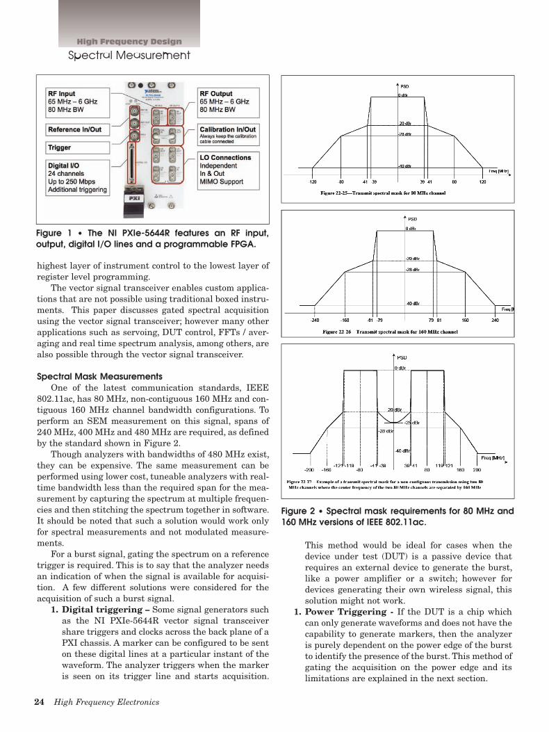
802.11ac, has 80 MHz, non-contiguous 160 MHz and con-tiguous 160 MHz channel bandwidth configurations. To perform an SEM measurement on this signal, spans of 240 MHz, 400 MHz and 480 MHz are required, as defined by the standard shown in Figure 2.
Though analyzers with bandwidths of 480 MHz exist, they can be expensive. The same measurement can be performed using lower cost, tuneable analyzers with real-time bandwidth less than the required span for the mea-surement by capturing the spectrum at multiple frequen-cies and then stitching the spectrum together in software. It should be noted that such a solution would work only for spectral measurements and not modulated measure-ments.
For a burst signal, gating the spectrum on a reference trigger is required. This is to say that the analyzer needs an indication of when the signal is available for acquisi-tion. A few different solutions were considered for the acquisition of such a burst signal.
1. Digital triggering – Some signal generators such as the NI PXIe-5644R vector signal transceiver share triggers and clocks across the back plane of a PXI chassis. A marker can be configured to be sent on these digital lines at a particular instant of the waveform. The analyzer triggers when the marker is seen on its trigger line and starts acquisition.
This method would be ideal for cases when the device under test (DUT) is a passive device that requires an external device to generate the burst, like a power amplifier or a switch; however for devices generating their own wireless signal, this solution might not work.
1. Power Triggering - If the DUT is a chip which can only generate waveforms and does not have the capability to generate markers, then the analyzer is purely dependent on the power edge of the burst to identify the presence of the burst. This method of gating the acquisition on the power edge and its limitations are explained in the next section.
Figure 1 • The NI PXIe-5644R features an RF input, output, digital I/O lines and a programmable FPGA.
Figure 2 • Spectral mask requirements for 80 MHz and 160 MHz versions of IEEE 802.11ac.
26 High Frequency Electronics
High Frequency Design
Spectral Measurement
1. Periodic Triggering – The rest of this article focuses on a unique method that combines the con-cept of gated acquisition and periodic triggering to overcome the limitations of wide band acquisition.
Power Trigger-Based Gated AcquisitionIn the absence of an external indicator of the presence
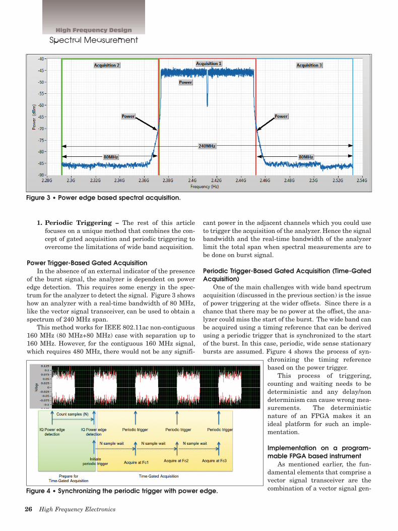
of the burst signal, the analyzer is dependent on power edge detection. This requires some energy in the spec-trum for the analyzer to detect the signal. Figure 3 shows how an analyzer with a real-time bandwidth of 80 MHz, like the vector signal transceiver, can be used to obtain a spectrum of 240 MHz span.
This method works for IEEE 802.11ac non-contiguous 160 MHz (80 MHz+80 MHz) case with separation up to 160 MHz. However, for the contiguous 160 MHz signal, which requires 480 MHz, there would not be any signifi-
cant power in the adjacent channels which you could use to trigger the acquisition of the analyzer. Hence the signal bandwidth and the real-time bandwidth of the analyzer limit the total span when spectral measurements are to be done on burst signal.
Periodic Trigger-Based Gated Acquisition (Time-Gated Acquisition)
One of the main challenges with wide band spectrum acquisition (discussed in the previous section) is the issue of power triggering at the wider offsets. Since there is a chance that there may be no power at the offset, the ana-lyzer could miss the start of the burst. The wide band can be acquired using a timing reference that can be derived using a periodic trigger that is synchronized to the start of the burst. In this case, periodic, wide sense stationary bursts are assumed. Figure 4 shows the process of syn-
chronizing the timing reference based on the power trigger.
This process of triggering, counting and waiting needs to be deterministic and any delay/non determinism can cause wrong mea-surements. The deterministic nature of an FPGA makes it an ideal platform for such an imple-mentation.
Implementation on a program-mable FPGA based instrument
As mentioned earlier, the fun-damental elements that comprise a vector signal transceiver are the combination of a vector signal gen-
Figure 3 • Power edge based spectral acquisition.
Figure 4 • Synchronizing the periodic trigger with power edge.

28 High Frequency Electronics
High Frequency Design
Spectral Measurement
erator (VSG) and vector signal analyser (VSA) with a shared FPGA for real-time signal processing and control. This is in contrast to traditional solutions, that either use two discrete instruments or wireless test sets that just combine the instruments in a common chassis. The pro-grammable FPGA of the vector signal transceiver has many benefits over implementing the algorithms required for time gated spectrum acquisition.
Single cycle time loop – The programmable FPGA on the vector signal transceiver can be clocked up to 200
MHz, allowing users to implement algorithms with a 5 ns iteration time. This is especially useful for detection of signals and implementation of triggers since the 200 MHz clock provides the timing accuracy required for time gated spectral acquisition. Figure 5 shows a single cycle timed loop implemented in the FPGA. Complex algo-rithms such as FFTs, triggering and decimation can also be implemented in the FPGA.
Reconfigurable/open firmware – The vector signal transceiver architecture consists of multiple, program-mable software layers, which enable the programmer detailed access to the complete software stack. This architecture includes multiple instrument design librar-ies, which allow programmers to configure the hardware through typical RF instrumentation parameters (e.g. attenuation, frequency, resolution bandwidth and span settings), and are disaggregated so that individual librar-ies can be interchanged without breaking dependencies on one another. In addition, the FPGA code aggregates multiple instrument design libraries into a specific design, with space reserved for additional user or applica-tion logic. Similarly, the host interface presents the FPGA capabilities in a familiar, logical fashion, though it is extendable to expose additional user-provided FPGA functionality. Figure 6 shows the generation and analysis software stack. The host VIs make calls to the FPGA and provide data. The FPGA VIs perform digital signal pro-cessing (DSP), triggering and acquisition control for analysis and base card configuration, waveform sequenc-ing, and DSP for the generation engine as well.
ImplementationOnce the signal is acquired and down-converted, the
IQ samples are available on the FPGA for processing. After the detection of a power trigger, a counter on the FPGA counts the number of samples until the next trig-ger occurs. The following algorithm lists out the steps for trigger generation:
1. Tune the local oscillator (LO) to the carrier fre-quency
Figure 5 • Single cycle timed loop provides enhanced timing accuracy.
Figure 6 • Open firmware software stack of vector signal transceiver.

September 2012 29
2. Detect the start of burst3. Start counter on FPGA4. Detect the next start of burst5. Reset the counter and register the count N6. Every time the counter reaches N, reset and send
internal trigger to the acquisition engine.Now, users can tune the LO of the analyzer to a differ-
ent frequency and wait until the periodic trigger sends the trigger to start acquiring. The accuracy of the counter is equal to the accuracy of the sample clock used by the analyzer. This method removes the limitation for span, in the case of simple gated spectrum, and the carrier fre-quency that can be tuned to is dependent on the frequen-cy range supported by the analyzer.
Figure 7 shows the signal process-ing performed on the acquired signal using NI LabVIEW system design soft-ware in a 120 MHz derived clock domain on the FPGA.
ConclusionThe combination of periodic trig-
gering and gated spectrum analysis, also known as time gated spectrum analysis, can do measurements such as spectrum emission mask for 802.11ac contiguous 160 MHz bandwidth (requiring a span of 480 MHz) using narrower bandwidth analyzers. Figure 8 shows the power spectral density obtained using the time-gated spec-trum. This method can be applied for other spectral measurements for wide band standards such as LTE Advanced.
Moreover, the programmable FPGA-based architecture of the NI PXIe-5644R vector signal transceiver allows engineers not only to imple-ment their own algorithms for time-gated spectrum analysis, but also mod-ify these algorithms, thus nullifying the
dependence on instrument vendors for such customized measurements.
Also, the programmable FPGA on the NI PXIe-5644R VST provides the timing accuracy and flexibility needed to implement the triggering and counting algorithms required for time gated spectral measurements.
About the Authors:The authors work at National Instruments, where
Raajit Lall is a Product Manager; Abhishek Rao is a Software Engineer; Sandeep Hari is a Software Engineer; and Vinay Kumar is a Software Engineer.
Figure 7 • Acquisition and processing of RF data using LabVIEW on FPGA.
Figure 8 • Power spectral density of IEEE 802.11 ac signals with contiguous and non-contiguous 160MHz (80MHz + 80MHz) configurations.