wilwood 2009 technical catalog
TRANSCRIPT

Revised:Revised:9 April 20099 April 2009

WARNING: The user or installer of any product from this catalog must determine its suitability for their intended purpose or application
www.wilwood.com
i
•W
HA
T’S
NE
WA
TW
ILW
OO
D•
WHAT’S NEW AT WILWOODWilwood never rests. We have been designing, testing and manufacturing new and improved items to enhance yourperformance automotive needs. On these pages are some of the highlights and where to find detailed informationon each product.
DynaPro Calipers - The next generation of full detail machined forged billet calipers with common mounting toupgrade from the traditional Dynalite series.
DynaPro Radial Mount - Page 32
DynaPro Six Piston - Page 34
DynaPro 5.25” Lug Mount - Page 36
DynaPro 3.50” Narrow Lug Mount - Page 38
DynaPro Single - Page 44
GM Metric - Cast Iron D154Replacement Calipers Page 51
Superlite 4 - FSL4 and FSL4/ST Forged BilletDifferential Bore Calipers - Page 28
W4AR - W6AR - W6AR/STForged Billet Radial Mount CalipersCaliper Page 12
CPB - Combination Parking BrakeHydra-Mechanical Caliper Page 45
GP 310 Color Motorcycle Calipers - Page 52

Brakes are critical safety components, see warnings and disclaimer on page 133
www.wilw
ood.com
ii
•W
HA
T’S
NE
WA
TW
ILW
OO
D•
Stealth - “Invisible” Motorcycle Brakes - Page 55
MPS - Mirror Polished StainlessRotors for Harley-DavidsonMotorcycles - Page 54
Brake Line Valve - Electric Shut Off Valve For Oval TrackPage 100
ProSpindle - 2” Drop Forged SteelSpindle for Mustang II BasedSuspensions - Page 112
Smart Pads - 3 New BPSeries Compounds For StreetAnd Track Pages 56 - 57
Black Electro Coat SRP Rotors withA New Revolutionary Coating That HasGreat Corrosion Resistant CharacteristicsPage 74 - 76

WARNING: The user or installer of any product from this catalog must determine its suitability for their intended purpose or application
www.wilwood.com
iii
•TA
BL
EO
FC
ON
TE
NT
S•
TABLE OF CONTENTSCalipers . . . . . . . . . . . . . . . . . . . . . . . . Pages 1-55Caliper Information . . . . . . . . . . . . . . . . . . . . . . . . . . . . . . . . . . . . 1STR Radial Mount . . . . . . . . . . . . . . . . . . . . . . . . . . . . . . . . . . . . 2P6R Radial Mount . . . . . . . . . . . . . . . . . . . . . . . . . . . . . . . . . . . . 4Integra 6R Radial Mount . . . . . . . . . . . . . . . . . . . . . . . . . . . . . . . 6Grand National GN lll, GN lll/ST . . . . . . . . . . . . . . . . . . . . . . . . . 8Forged TC 6R . . . . . . . . . . . . . . . . . . . . . . . . . . . . . . . . . . . . . . 10W6A / W4A Radial Mount . . . . . . . . . . . . . . . . . . . . . . . . . . . . . . 12Superlite SL6R, SL6R/ST Radial Mount . . . . . . . . . . . . . . . . . . 14Superlite SL4R/ST Radial Mount . . . . . . . . . . . . . . . . . . . . . . . . 17Superlite SL6R/4R Radial Mount for 14" Rotors . . . . . . . . . . . . . .18Superlite SL6, SL6/ST . . . . . . . . . . . . . . . . . . . . . . . . . . . . . . . 20Superlite SL4, SL4/ST . . . . . . . . . . . . . . . . . . . . . . . . . . . . . . . 24Forged Superlite, FSL4 . . . . . . . . . . . . . . . . . . . . . . . . . . . . . . 26Forged Superlite, FSL4, FSL4/ST Differential Bore . . . . . . . . . . . 28D8-4 . . . . . . . . . . . . . . . . . . . . . . . . . . . . . . . . . . . . . . . . . . . . . 29aIR-GT4R Radial Mount . . . . . . . . . . . . . . . . . . . . . . . . . . . . . . . . 30Powerlite . . . . . . . . . . . . . . . . . . . . . . . . . . . . . . . . . . . . . . . . . . 31DynaPro, DynaPro-13 Radial Mount DPR . . . . . . . . . . . . . . . . . . 32DynaPro 6 Lug Mount, DP6 . . . . . . . . . . . . . . . . . . . . . . . . . . . . 34DynaPro Lug Mount , DP. . . . . . . . . . . . . . . . . . . . . . . . . . . . . . 36Billet Narrow Mount DynaPro, NDP . . . . . . . . . . . . . . . . . . . . . . 38Narrow Mount Dynalite, NDL . . . . . . . . . . . . . . . . . . . . . . . . . . . 40Forged Dynalite, FDL . . . . . . . . . . . . . . . . . . . . . . . . . . . . . . . . 42Billet DynaPro Single, DPS . . . . . . . . . . . . . . . . . . . . . . . . . . . . 44Combination Parking Brake . . . . . . . . . . . . . . . . . . . . . . . . . . . . 45GP 320 . . . . . . . . . . . . . . . . . . . . . . . . . . . . . . . . . . . . . . . . . . . 46Dynalite Single Floating Mount, DLSF . . . . . . . . . . . . . . . . . . . . 47Kart / Jr. Dragster . . . . . . . . . . . . . . . . . . . . . . . . . . . . . . . . . . . 48PS-1 . . . . . . . . . . . . . . . . . . . . . . . . . . . . . . . . . . . . . . . . . . . . . 48GM lll Floating Mount . . . . . . . . . . . . . . . . . . . . . . . . . . . . . . . . . 49GM Metric Floating Mount . . . . . . . . . . . . . . . . . . . . . . . . . . . . . 50GM Iron Metric Floating . . . . . . . . . . . . . . . . . . . . . . . . . . . . . . . 51Motorcycle (including rotors) . . . . . . . . . . . . . . . . . . . . . . . . . . . . 52Stealth Motorcycle Brake System . . . . . . . . . . . . . . . . . . . . . . . . 55
Brake Pads . . . . . . . . . . . . . . . . . . . . . Pages 56-65Compound Guide . . . . . . . . . . . . . . . . . . . . . . . . . . . . . . . . . . . 56Pad Bedding Procedure . . . . . . . . . . . . . . . . . . . . . . . . . . . . . . 57Pad Diagrams and Applications . . . . . . . . . . . . . . . . . . . . . . . . 59
Rotors . . . . . . . . . . . . . . . . . . . . . . . . Pages 66-81Rotor Information. . . . . . . . . . . . . . . . . . . . . . . . . . . . . . . . . . . . 66SV-GT Staggered Directional Vane. . . . . . . . . . . . . . . . . . . . . . . 67GT Directional Vane . . . . . . . . . . . . . . . . . . . . . . . . . . . . . . . . . 68HD Directional Vane . . . . . . . . . . . . . . . . . . . . . . . . . . . . . . . . . 70UL Directional Vane. . . . . . . . . . . . . . . . . . . . . . . . . . . . . . . . . . 71UL Straight Vane . . . . . . . . . . . . . . . . . . . . . . . . . . . . . . . . . . . . 72ULD Drilled Straight Vane . . . . . . . . . . . . . . . . . . . . . . . . . . . . . 73ULS Scalloped Straight Vane . . . . . . . . . . . . . . . . . . . . . . . . . . 73SRP Performance Drilled and Slotted . . . . . . . . . . . . . . . . . . . . 74Disc / Drum for Internal Parking Brakes . . . . . . . . . . . . . . . . . . 76Dynamic Mount Steel. . . . . . . . . . . . . . . . . . . . . . . . . . . . . . . . . 78Fixed Mount Steel . . . . . . . . . . . . . . . . . . . . . . . . . . . . . . . . . . . 79Aluminum . . . . . . . . . . . . . . . . . . . . . . . . . . . . . . . . . . . . . . . . . 80Rotor Bedding-in . . . . . . . . . . . . . . . . . . . . . . . . . . . . . . . . . . . . 81

Brakes are critical safety components, see warnings and disclaimer on page 133
www.wilw
ood.com
iv
•TA
BL
EO
FC
ON
TE
NT
S•
Rotor Mounting Hats and Plates . . . . Pages 82-87Dynamic Mount Plates . . . . . . . . . . . . . . . . . . . . . . . . . . . . . . . . 82GT Series Dynamic Mount Hats . . . . . . . . . . . . . . . . . . . . . . . . 83GT Series Fixed Mount Hats . . . . . . . . . . . . . . . . . . . . . . . . . . . 84HD Series Fixed Mount Hats . . . . . . . . . . . . . . . . . . . . . . . . . . . 86Open Wheel Live Axle Clamp . . . . . . . . . . . . . . . . . . . . . . . . . . 87
Wide 5 Hubs . . . . . . . . . . . . . . . . . . . . Pages 88-90Starlite “55” . . . . . . . . . . . . . . . . . . . . . . . . . . . . . . . . . . . . . . . . 88Starlite Wide 5 . . . . . . . . . . . . . . . . . . . . . . . . . . . . . . . . . . . . . . 89Wide 5 Hub Parts and Accessories. . . . . . . . . . . . . . . . . . . . . . . 90
Rotor Bolt Kits . . . . . . . . . . . . . . . . . . . . . Page 91
Pedal Assemblies . . . . . . . . . . . . . . . Pages 92-98Floor Mount Pedals . . . . . . . . . . . . . . . . . . . . . . . . . . . . . . . . . . 92Forward Swing Mount Pedals . . . . . . . . . . . . . . . . . . . . . . . . . . 93Reverse Swing Mount Pedals. . . . . . . . . . . . . . . . . . . . . . . . . . . 94Remote Brake Bias Adjuster . . . . . . . . . . . . . . . . . . . . . . . . . . . 9660 Degree Balance Pedal Assembly . . . . . . . . . . . . . . . . . . . . . 96
Master Cylinders, Fluids & Controls . . Pages 99-110Proportioning Valves . . . . . . . . . . . . . . . . . . . . . . . . . . . . . . . . . 99Pressure Gauge . . . . . . . . . . . . . . . . . . . . . . . . . . . . . . . . . . . . 99Line Shut-Off Valve . . . . . . . . . . . . . . . . . . . . . . . . . . . . . . . . . . 100Self Bleed Lines and Check Valves . . . . . . . . . . . . . . . . . . . . . . 101Compact “Short” Combination Master Cylinders . . . . . . . . . . . .101aCombination Remote Master Cylinders . . . . . . . . . . . . . . . . . . 101bHigh Volume Aluminum Master Cylinders . . . . . . . . . . . . . . . . . 102Compact Remote Reservoir Master Cylinders . . . . . . . . . . . . . . 103Clutch and Small Brake Master Cylinders . . . . . . . . . . . . . . . . . 103Tandem Integral Reservoir Master Cylinders . . . . . . . . . . . . . . . 104Kart / Jr. Dragster Master Cylinder . . . . . . . . . . . . . . . . . . . . . . 104Combination Remote Tandem Master Cylinder . . . . . . . . . . . . . 105TM1 Tandem Master Cylinder . . . . . . . . . . . . . . . . . . . . . . . . . . 106Aluminum Tandem Chamber Master Cylinders. . . . . . . . . . . . . . 107Residual Pressure Valves . . . . . . . . . . . . . . . . . . . . . . . . . . . . . 108Slave Cylinder . . . . . . . . . . . . . . . . . . . . . . . . . . . . . . . . . . . . . 108EXP 600 Plus and Hi-Temp° 570 Fluid . . . . . . . . . . . . . . . . . . . 110
Thermlock® Pistons . . . . . . . . . . . . . . . . Page 109T1 and T2 Type Thermlock® Pistons . . . . . . . . . . . . . . . . . . . . . 109
Plumbing Kits and Components . . . . . . . Page 111Fitting and Adapters . . . . . . . . . . . . . . . . . . . . . . . . . . . . . . . . . 111Stainless Braided Flexlines . . . . . . . . . . . . . . . . . . . . . . . . . . . . 111
Steering . . . . . . . . . . . . . . . . . . . . . . Pages 112-114Wilwood ProSpindle . . . . . . . . . . . . . . . . . . . . . . . . . . . . . . . . . 112Rack and Pinion . . . . . . . . . . . . . . . . . . . . . . . . . . . . . . . . . . . . 114Quick Release Steering Wheel Hubs . . . . . . . . . . . . . . . . . . . . 114
Bolt-On Brake Kits . . . . . . . . . . . . . Pages 115-127Kit Group Overview . . . . . . . . . . . . . . . . . . . . . . . . . . . . . . . . . 115Application Index by Fitment Code . . . . . . . . . . . . . . . . . . . . . .123
Trouble Shooting / Tech Tips . . . . . Pages 128-132
WARNING: The user or installer of any product from this catalog must determine its suitability for their intended purpose or application
www.wilwood.com
v
•IN
TR
OD
UC
TIO
N•
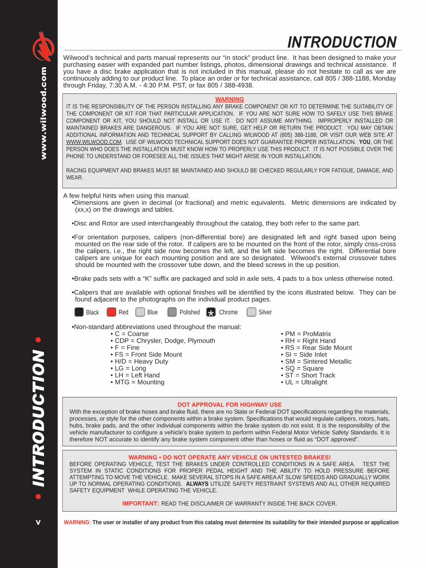
INTRODUCTIONWilwood’s technical and parts manual represents our “in stock” product line. It has been designed to make yourpurchasing easier with expanded part number listings, photos, dimensional drawings and technical assistance. Ifyou have a disc brake application that is not included in this manual, please do not hesitate to call as we arecontinuously adding to our product line. To place an order or for technical assistance, call 805 / 388-1188, Mondaythrough Friday, 7:30 A.M. - 4:30 P.M. PST, or fax 805 / 388-4938.
A few helpful hints when using this manual:•Dimensions are given in decimal (or fractional) and metric equivalents. Metric dimensions are indicated by(xx,x) on the drawings and tables.
•Disc and Rotor are used interchangeably throughout the catalog, they both refer to the same part.
•For orientation purposes, calipers (non-differential bore) are designated left and right based upon beingmounted on the rear side of the rotor. If calipers are to be mounted on the front of the rotor, simply criss-crossthe calipers, i.e., the right side now becomes the left, and the left side becomes the right. Differential borecalipers are unique for each mounting position and are so designated. Wilwood’s external crossover tubesshould be mounted with the crossover tube down, and the bleed screws in the up position.
•Brake pads sets with a “K” suffix are packaged and sold in axle sets, 4 pads to a box unless otherwise noted.
•Calipers that are available with optional finishes will be identified by the icons illustrated below. They can befound adjacent to the photographs on the individual product pages.
•Non-standard abbreviations used throughout the manual:• C = Coarse• CDP = Chrysler, Dodge, Plymouth• F = Fine• FS = Front Side Mount• H/D = Heavy Duty• LG = Long• LH = Left Hand• MTG = Mounting
• PM = ProMatrix• RH = Right Hand• RS = Rear Side Mount• SI = Side Inlet• SM = Sintered Metallic• SQ = Square• ST = Short Track• UL = Ultralight
WARNING • DO NOT OPERATE ANY VEHICLE ON UNTESTED BRAKES!BEFORE OPERATING VEHICLE, TEST THE BRAKES UNDER CONTROLLED CONDITIONS IN A SAFE AREA. TEST THESYSTEM IN STATIC CONDITIONS FOR PROPER PEDAL HEIGHT AND THE ABILITY TO HOLD PRESSURE BEFOREATTEMPTING TO MOVE THE VEHICLE. MAKE SEVERAL STOPS IN A SAFE AREAAT SLOW SPEEDS AND GRADUALLY WORKUP TO NORMAL OPERATING CONDITIONS. ALWAYS UTILIZE SAFETY RESTRAINT SYSTEMS AND ALL OTHER REQUIREDSAFETY EQUIPMENT WHILE OPERATING THE VEHICLE.
IMPORTANT: READ THE DISCLAIMER OF WARRANTY INSIDE THE BACK COVER.
DOT APPROVAL FOR HIGHWAY USEWith the exception of brake hoses and brake fluid, there are no State or Federal DOT specifications regarding the materials,processes, or style for the other components within a brake system. Specifications that would regulate calipers, rotors, hats,hubs, brake pads, and the other individual components within the brake system do not exist. It is the responsibility of thevehicle manufacturer to configure a vehicle's brake system to perform within Federal Motor Vehicle Safety Standards. It istherefore NOT accurate to identify any brake system component other than hoses or fluid as “DOT approved”.
Polished Chrome*
WARNINGIT IS THE RESPONSIBILITY OF THE PERSON INSTALLING ANY BRAKE COMPONENT OR KIT TO DETERMINE THE SUITABILITY OFTHE COMPONENT OR KIT FOR THAT PARTICULAR APPLICATION. IF YOU ARE NOT SURE HOW TO SAFELY USE THIS BRAKECOMPONENT OR KIT, YOU SHOULD NOT INSTALL OR USE IT. DO NOT ASSUME ANYTHING. IMPROPERLY INSTALLED ORMAINTAINED BRAKES ARE DANGEROUS. IF YOU ARE NOT SURE, GET HELP OR RETURN THE PRODUCT. YOU MAY OBTAINADDITIONAL INFORMATION AND TECHNICAL SUPPORT BY CALLING WILWOOD AT (805) 388-1188, OR VISIT OUR WEB SITE ATWWW.WILWOOD.COM. USE OF WILWOOD TECHNICAL SUPPORT DOES NOT GUARANTEE PROPER INSTALLATION. YOU, OR THEPERSON WHO DOES THE INSTALLATION MUST KNOW HOW TO PROPERLY USE THIS PRODUCT. IT IS NOT POSSIBLE OVER THEPHONE TO UNDERSTAND OR FORESEE ALL THE ISSUES THAT MIGHT ARISE IN YOUR INSTALLATION.
RACING EQUIPMENT AND BRAKES MUST BE MAINTAINED AND SHOULD BE CHECKED REGULARLY FOR FATIGUE, DAMAGE, ANDWEAR.
Black Blue SilverRed
Brakes are critical safety components, see warnings and disclaimer on page 133
www.wilw
ood.com
1
•C
AL
IPE
RS
•CALIPER INFORMATION:
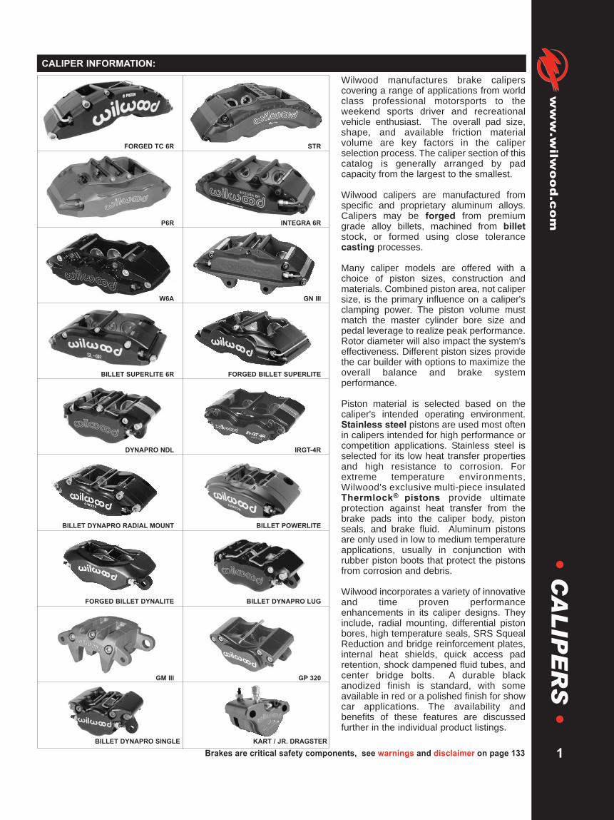
Wilwood manufactures brake caliperscovering a range of applications from worldclass professional motorsports to theweekend sports driver and recreationalvehicle enthusiast. The overall pad size,shape, and available friction materialvolume are key factors in the caliperselection process. The caliper section of thiscatalog is generally arranged by padcapacity from the largest to the smallest.
Wilwood calipers are manufactured fromspecific and proprietary aluminum alloys.Calipers may be forged from premiumgrade alloy billets, machined from billetstock, or formed using close tolerancecasting processes.
Many caliper models are offered with achoice of piston sizes, construction andmaterials. Combined piston area, not calipersize, is the primary influence on a caliper'sclamping power. The piston volume mustmatch the master cylinder bore size andpedal leverage to realize peak performance.Rotor diameter will also impact the system'seffectiveness. Different piston sizes providethe car builder with options to maximize theoverall balance and brake systemperformance.
Piston material is selected based on thecaliper's intended operating environment.Stainless steel pistons are used most oftenin calipers intended for high performance orcompetition applications. Stainless steel isselected for its low heat transfer propertiesand high resistance to corrosion. Forextreme temperature environments,Wilwood's exclusive multi-piece insulatedThermlock® pistons provide ultimateprotection against heat transfer from thebrake pads into the caliper body, pistonseals, and brake fluid. Aluminum pistonsare only used in low to medium temperatureapplications, usually in conjunction withrubber piston boots that protect the pistonsfrom corrosion and debris.
Wilwood incorporates a variety of innovativeand time proven performanceenhancements in its caliper designs. Theyinclude, radial mounting, differential pistonbores, high temperature seals, SRS SquealReduction and bridge reinforcement plates,internal heat shields, quick access padretention, shock dampened fluid tubes, andcenter bridge bolts. A durable blackanodized finish is standard, with someavailable in red or a polished finish for showcar applications. The availability andbenefits of these features are discussedfurther in the individual product listings.
FORGED TC 6R STR
P6R INTEGRA 6R
W6A GN III
BILLET SUPERLITE 6R FORGED BILLET SUPERLITE
DYNAPRO NDL IRGT-4R
BILLET DYNAPRO RADIAL MOUNT BILLET POWERLITE
FORGED BILLET DYNALITE BILLET DYNAPRO LUG
GM III GP 320
BILLET DYNAPRO SINGLE KART / JR. DRAGSTER

WARNING: The user or installer of any product from this catalog must determine its suitability for their intended purpose or application
www.wilwood.com
2
•C
AL
IPE
RS
•STR RADIAL MOUNT CALIPER
Caliper Highlights:Wilwood's STR radial mount caliper is the result of extensivetesting and development focused on overcoming racing'smost demanding high temp conditions. There are nobrake tests tougher than stock cars racing on thelegendary short tracks and road courses likeMartinsville and Watkins Glen. The STR caliperis engineered to maximize braking underthese extreme conditions.
The development of the STR caliper began withFEA structural design and stress analysis. Thegoal was to achieve a highly efficient clampingforce with the lowest amount of deflection and fluiddisplacement resulting in a firm, consistent pedal feel for the driver. Thecaliper accommodates the widest, most thermally efficient rotor ever built. Extensiveprototype testing and development has minimized structural deflection and volume displacement on thiscaliper and support components. The STR easily outperforms other short track systems in comparison testing withvastly superior heat management.
Weighing just 10.38 pounds, the STR features a six piston differential bore configuration that is easily matched withcommon pedal ratios and master cylinder bore sizes. The size, and location of each piston effectively varies thepressure load to compensate for natural temperature changes that occur over the length of the pad. This assures flatpad wear during extreme heat build-up on long green flag runs. Wilwood's exclusive Thermlock® T2 pistonsdramatically reduce heat transfer from the pads to the caliper body, piston seals, and fluid. This not only maintainssafe and manageable caliper operating temperatures, it also keeps the heat in the pads where it can be properlyremoved by the rotor. A total of ten pre-loaded bridge bolts provide unmatched strength. The center bridge barprovides additional strength, and also accommodates quick and easy pad changes without caliper removal.Two-piece bleed assemblies enable hot bleeding without the risk of seat damage in the caliper body. All fluid tubesare vibration dampened to resist stress fractures and reduce the possibility of damage from track debris. Not only isthis caliper stronger than mono-block designs, it is far easier and faster to service at the track.
The STR caliper uses PolyMatrix 9330 type brake pads in the compounds most suited to severe duty competition.
Wilwood’s unique Thermlock® T2 Short Track Piston isstandard in our STR calipers, for complete details and across-section line drawing, please refer to page 109.
1.62” (41,9 mm) Diameter - Order P/N: 200-73981.25” (31,8 mm) Diameter - Order P/N: 200-7402
NOTES: (1) REFERENCE FRONT OF MANUAL FOR GENERAL ORDERING INFORMATION
CALIPER ORDERING INFORMATION:(1)
FRONT MOUNT PART NO. REAR MOUNT PART NO.BORE SIZE DISC WIDTH RH LH RH LH
1.62 / 1.25 / 1.25” 1.62” 41,1 mm 120-7482-FS 120-7483-FS 120-7482-RS 120-7483-RS41,1 / 31,8 / 31,8 mm
CALIPER MOUNTING BRACKET KIT 7.80” (198,1) RADIAL TO 5.25” (133,4) GT LUG - P/N: 250-7426
THERMLOCK T2 SHORT TRACK PISTON:

CALIPER THERMLOCK SQ RING BLEED SCREW CROSSOVER SELF-BLEED BRIDGE BRIDGE WEAR MOUNT BOLTPART NO. PISTON KIT (6 PK) KIT (4 PK) TUBE KIT (2 PK) TUBE (EA) BAR KIT PLATE (EA) AND SHIM KIT
120-7482 200-7402 (1.25”) 130-5660 220-6069 190-7547 190-7507 300-7546 300-7490 230-7031200-7398 (1.62”)
120-7483 200-7402 (1.25”) 130-5660 220-6069 190-7547 190-7507 300-7546 300-7490 230-7031200-7398 (1.62”)
DISC ROTATION
1.62 (41,1)
PISTON
1.25 (31,8)
PISTON
1.25 (31,8)
PISTON
11.76 (298,7)
7.80 (198,1)
MOUNT CENTER
DIMENSIONS FOR USE WITH
A 12.88 (327,2) X 1.62 (41,1) DISC
NOTE: RIGHT HAND, REAR MOUNT
CALIPER SHOWN - INLET FITTING: 1/8-27 NPT
4.15 (105,4)
2.29 (58,2)
MOUNT
HEIGHT
DISC/WHEEL CENTERLINE
2.00 (50,8)
MOUNT OFFSET7.18 (182,4)
OUTSIDE RADIUS
3.32 (84,3) 3.32 (84,3)
TOP OF FRICTION MATERIAL AND
DISC O.D. TO BE FLUSH
1.62 (41,1)
DISC WIDTH
.675 (17,1)
.190 (4,8)
7.80 (198,1)
5.25 (133,4)
MOUNT CENTER
.45 (11,4)
MOUNT HOLE
Brakes are critical safety components, see warnings and disclaimer on page 133
www.wilw
ood.com
3
•C
AL
IPE
RS
•STR CALIPER, MOUNTING DIMENSIONS:
SERVICE PARTS ORDERING INFORMATION:
RADIAL CALIPER TO LUG MOUNT ADAPTER BRACKET, PART NUMBER 250-7426 - STEEL:
2.77
(70,4)
5.98 (151,9) 1.18
(30,0)
AXLE SET P/N PAD TYPE / COMPOUND15A - 7509K 9330 A PolyMatrix15H - 8119K 9330 H PolyMatrix
STR BRAKE PAD TYPE 9330 - PAD VOLUME = 13.2 CU. IN.:
WARNING: The user or installer of any product from this catalog must determine its suitability for their intended purpose or application
www.wilwood.com
4
•C
AL
IPE
RS
•P6R RADIAL MOUNT CALIPER
FRICTION PAD
LOAD SURFACE
SEAL
CONTACT
SURFACE
INNER
SHIELD
THERMLOCK T2 PISTON CROSS-SECTION
OUTER
SHELL
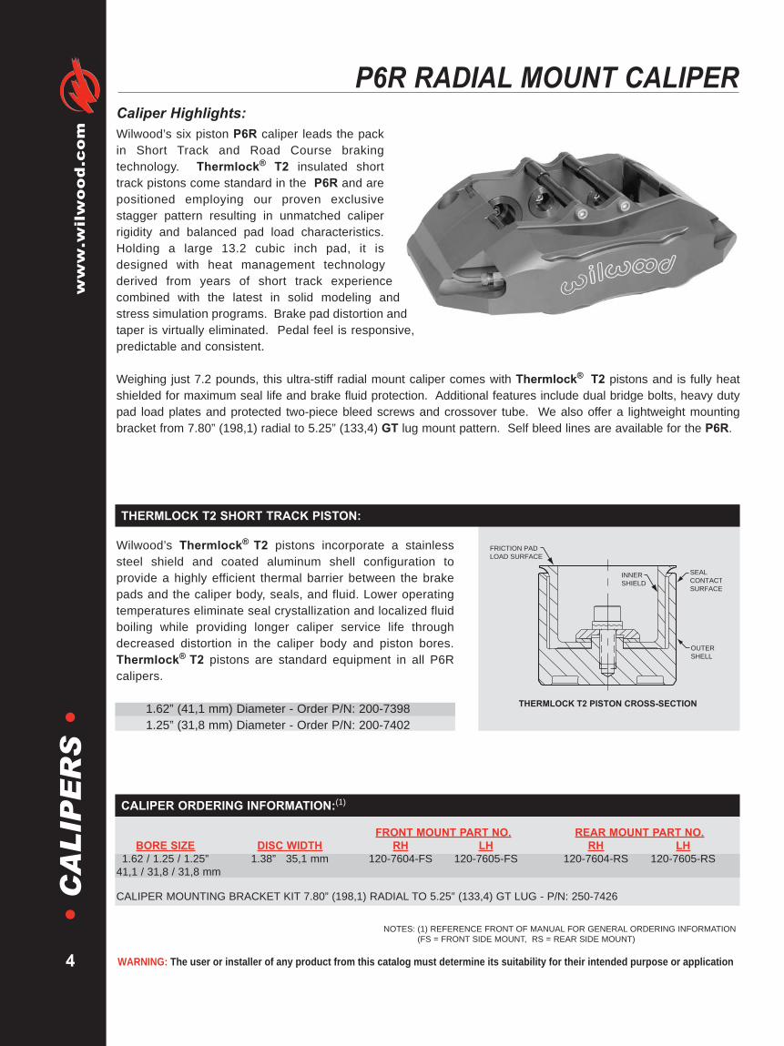
Caliper Highlights:Wilwood’s six piston P6R caliper leads the packin Short Track and Road Course brakingtechnology. Thermlock® T2 insulated shorttrack pistons come standard in the P6R and arepositioned employing our proven exclusivestagger pattern resulting in unmatched caliperrigidity and balanced pad load characteristics.Holding a large 13.2 cubic inch pad, it isdesigned with heat management technologyderived from years of short track experiencecombined with the latest in solid modeling andstress simulation programs. Brake pad distortion andtaper is virtually eliminated. Pedal feel is responsive,predictable and consistent.
Weighing just 7.2 pounds, this ultra-stiff radial mount caliper comes with Thermlock® T2 pistons and is fully heatshielded for maximum seal life and brake fluid protection. Additional features include dual bridge bolts, heavy dutypad load plates and protected two-piece bleed screws and crossover tube. We also offer a lightweight mountingbracket from 7.80” (198,1) radial to 5.25” (133,4) GT lug mount pattern. Self bleed lines are available for the P6R.
Wilwood’s Thermlock® T2 pistons incorporate a stainlesssteel shield and coated aluminum shell configuration toprovide a highly efficient thermal barrier between the brakepads and the caliper body, seals, and fluid. Lower operatingtemperatures eliminate seal crystallization and localized fluidboiling while providing longer caliper service life throughdecreased distortion in the caliper body and piston bores.Thermlock® T2 pistons are standard equipment in all P6Rcalipers.
1.62” (41,1 mm) Diameter - Order P/N: 200-73981.25” (31,8 mm) Diameter - Order P/N: 200-7402
NOTES: (1) REFERENCE FRONT OF MANUAL FOR GENERAL ORDERING INFORMATION(FS = FRONT SIDE MOUNT, RS = REAR SIDE MOUNT)
CALIPER ORDERING INFORMATION:(1)
FRONT MOUNT PART NO. REAR MOUNT PART NO.BORE SIZE DISC WIDTH RH LH RH LH
1.62 / 1.25 / 1.25” 1.38” 35,1 mm 120-7604-FS 120-7605-FS 120-7604-RS 120-7605-RS41,1 / 31,8 / 31,8 mm
CALIPER MOUNTING BRACKET KIT 7.80” (198,1) RADIAL TO 5.25” (133,4) GT LUG - P/N: 250-7426
THERMLOCK T2 SHORT TRACK PISTON:

Brakes are critical safety components, see warnings and disclaimer on page 133
www.wilw
ood.com
DISC ROTATION
1.62
(41,1)
PISTON
1.25
(31,8)
PISTON
1.25
(31,8)
PISTON
11.02 (279,9)
7.80 (198,1)
MOUNT CENTER
DIMENSIONS FOR USE WITH
A 12.88 (327,2) X 1.38 (35,0) DISC
NOTE: RIGHT HAND, REAR MOUNT
CALIPER SHOWN - INLET FITTING: 1/8-27 NPT
4.32 (109,7)
2.12 (53,8)
MOUNT
HEIGHT
DISC/WHEEL CENTERLINE
1.75 (44,5)
MOUNT
OFFSET
7.23
(183,6)
OUTSIDE
RADIUS
3.04 (77,2) 3.04 (77,2)
TOP OF FRICTION MATERIAL AND
DISC O.D. TO BE FLUSH1.38 (35,1)
DISC WIDTH
.675 (17,1)
.190 (4,8)
7.80 (198,1)
5.25 (133,4)
MOUNT CENTER
.45 (11,4)
MOUNT HOLE
2.77 (70,4)
5.98 (151,9) 1.18
(30,0)
CALIPER THERMLOCK SQ RING BLEED SCREW CROSSOVER SELF-BLEED BRIDGE BRIDGE WEAR MOUNT BOLTPART NO. PISTON KIT (6 PK) KIT (4 PK) TUBE KIT (2 PK) TUBE (EA) BOLT KIT PLATE (EA) AND SHIM KIT
120-7604 200-7402 (1.25”) 130-5660 220-0627 190-5669 190-5604 230-6819 300-5712 (R/H) 230-7031200-7398 (1.62”) 300-5713 (L/H)
120-7605 200-7402 (1.25”) 130-5660 220-0627 190-5669 190-5604 230-6819 300-5712 (R/H) 230-7031200-7398 (1.62”) 300-5713 (L/H)
5
•C
AL
IPE
RS
•P6R RADIAL MOUNT CALIPER, MOUNTING DIMENSIONS:
AXLE SET P/N PAD TYPE / COMPOUND15A - 5742K 9930 A PolyMatrix15H - 8107K 9930 H PolyMatrix
SERVICE PARTS ORDERING INFORMATION:
RADIAL CALIPER TO LUG MOUNT ADAPTER BRACKET, PART NUMBER 250-7426 - STEEL:
P6R BRAKE PAD TYPE 9930 - PAD VOLUME = 13.2 CU. IN.:

WARNING: The user or installer of any product from this catalog must determine its suitability for their intended purpose or application
www.wilwood.com
6
•C
AL
IPE
RS
•INTEGRA 6R RADIAL MOUNT CALIPER
Caliper Highlights:Wilwood’s six piston Integra 6R caliper utilizessophisticated Finite Element Analysis, StressSimulation and Heat Management programs toprovide a powerhouse of stopping performanceweighing just 5.50 pounds. The Integra 6R caliperemploys our proven exclusive piston stagger patternresulting in unmatched caliper rigidity and balancedpad load characteristics; brake pad distortion andtaper is virtually eliminated. The fully heat shieldeddesign provides phenomenal heat protection for aconsistent, responsive pedal throughout the longestraces.
Three different pad and rotor combinations are utilized with this caliper depending on race requirements: short track/road course, intermediate track and super speedways or qualifying. With the Integra 6R caliper, brake performanceis maximized while maintaining the lowest possible unsprung weight. All Wilwood Integra calipers come standardwith Thermlock® T2 insulated short track pistons for maximum heat protection.
We also offer a lightweight mounting bracket, either aluminum or steel from 7.09” (180,0) radial to 5.25” (133,4) GTlug mount pattern. Self bleed lines are also available for these calipers.
NOTES: (1) REFERENCE FRONT OF MANUAL FOR GENERAL ORDERING INFORMATION(FS = FRONT SIDE MOUNT, RS = REAR SIDE MOUNT)
CALIPER ORDERING INFORMATION:(1)
FRONT MOUNT PART NO. REAR MOUNT PART NO.BORE SIZE DISC WIDTH RH LH RH LH
1.62 / 1.25 / 1.25” 1.38 / 1.31 / 1.25” 120-5690-FS 120-5691-FS 120-5690-RS 120-5691-RS41,1 / 31,8 / 31,8 mm 35,1 / 33,3 / 31,8 mm
CALIPER MOUNTING BRACKET KIT 7.09” (180,0) RADIAL TO 5.25” (133,4) GT LUGALUMINUM BRACKET P/N: 250-5687STEEL BRACKET P/N: 250-7423
FRICTION PAD
LOAD SURFACE
SEAL
CONTACT
SURFACE
INNER
SHIELD
THERMLOCK T2 PISTON CROSS-SECTION
OUTER
SHELL
Wilwood’s Thermlock® T2 pistons incorporate a stainlesssteel shield and coated aluminum shell configuration toprovide a highly efficient thermal barrier between the brakepads and the caliper body, seals, and fluid. Lower operatingtemperatures eliminate seal crystallization and localized fluidboiling while providing longer caliper service life throughdecreased distortion in the caliper body and piston bores.Thermlock® T2 pistons are standard equipment in all Integracalipers.
1.62” (41,1 mm) Diameter - Order P/N: 200-73981.25” (31,8 mm) Diameter - Order P/N: 200-7402
THERMLOCK T2 SHORT TRACK PISTON:
Black
1.62
(41,1)
PISTON1.25 (31,8)
PISTON
1.25 (31,8)
PISTON
DISC ROTATION
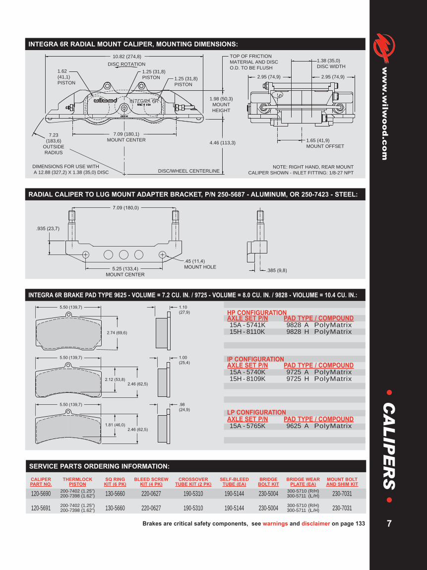
10.82 (274,8)
7.09 (180,1)
MOUNT CENTER7.23
(183,6)
OUTSIDE
RADIUS
1.98 (50,3)
MOUNT
HEIGHT
4.46 (113,3)
DISC/WHEEL CENTERLINE
TOP OF FRICTION
MATERIAL AND DISC
O.D. TO BE FLUSH
1.65 (41,9)
MOUNT OFFSET
1.38 (35,0)
DISC WIDTH
2.95 (74,9)2.95 (74,9)
DIMENSIONS FOR USE WITH
A 12.88 (327,2) X 1.38 (35,0) DISCNOTE: RIGHT HAND, REAR MOUNT
CALIPER SHOWN - INLET FITTING: 1/8-27 NPT
.935 (23,7)
.385 (9,8)
7.09 (180,0)
5.25 (133,4)
MOUNT CENTER
.45 (11,4)
MOUNT HOLE
2.46 (62,5)
5.50 (139,7) .98
(24,9)
2.46 (62,5)2.12 (53,8)
1.81 (46,0)
5.50 (139,7) 1.00
(25,4)
2.74 (69,6)
5.50 (139,7) 1.10
(27,9)
CALIPER THERMLOCK SQ RING BLEED SCREW CROSSOVER SELF-BLEED BRIDGE BRIDGE WEAR MOUNT BOLTPART NO. PISTON KIT (6 PK) KIT (4 PK) TUBE KIT (2 PK) TUBE (EA) BOLT KIT PLATE (EA) AND SHIM KIT
120-5690 200-7402 (1.25”) 130-5660 220-0627 190-5310 190-5144 230-5004 300-5710 (R/H) 230-7031200-7398 (1.62”) 300-5711 (L/H)
120-5691 200-7402 (1.25”) 130-5660 220-0627 190-5310 190-5144 230-5004 300-5710 (R/H) 230-7031200-7398 (1.62”) 300-5711 (L/H)
Brakes are critical safety components, see warnings and disclaimer on page 133
www.wilw
ood.com
7
•C
AL
IPE
RS
•INTEGRA 6R RADIAL MOUNT CALIPER, MOUNTING DIMENSIONS:
HP CONFIGURATIONAXLE SET P/N PAD TYPE / COMPOUND15A - 5741K 9828 A PolyMatrix15H - 8110K 9828 H PolyMatrix
IP CONFIGURATIONAXLE SET P/N PAD TYPE / COMPOUND15A - 5740K 9725 A PolyMatrix15H - 8109K 9725 H PolyMatrix
LP CONFIGURATIONAXLE SET P/N PAD TYPE / COMPOUND15A - 5765K 9625 A PolyMatrix
SERVICE PARTS ORDERING INFORMATION:
RADIAL CALIPER TO LUG MOUNT ADAPTER BRACKET, P/N 250-5687 - ALUMINUM, OR 250-7423 - STEEL:
INTEGRA 6R BRAKE PAD TYPE 9625 - VOLUME = 7.2 CU. IN. / 9725 - VOLUME = 8.0 CU. IN. / 9828 - VIOLUME = 10.4 CU. IN.:
WARNING: The user or installer of any product from this catalog must determine its suitability for their intended purpose or application
www.wilwood.com
8
•C
AL
IPE
RS
•GN III AND GN III /ST CALIPERS
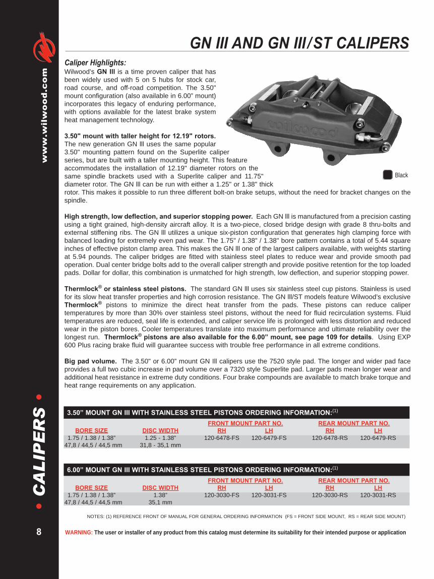
Caliper Highlights:Wilwood’s GN lll is a time proven caliper that hasbeen widely used with 5 on 5 hubs for stock car,road course, and off-road competition. The 3.50"mount configuration (also available in 6.00” mount)incorporates this legacy of enduring performance,with options available for the latest brake systemheat management technology.
3.50" mount with taller height for 12.19" rotors.The new generation GN lll uses the same popular3.50" mounting pattern found on the Superlite caliperseries, but are built with a taller mounting height. This featureaccommodates the installation of 12.19" diameter rotors on thesame spindle brackets used with a Superlite caliper and 11.75"diameter rotor. The GN lll can be run with either a 1.25" or 1.38" thickrotor. This makes it possible to run three different bolt-on brake setups, without the need for bracket changes on thespindle.
High strength, low deflection, and superior stopping power. Each GN lll is manufactured from a precision castingusing a tight grained, high-density aircraft alloy. It is a two-piece, closed bridge design with grade 8 thru-bolts andexternal stiffening ribs. The GN lll utilizes a unique six-piston configuration that generates high clamping force withbalanced loading for extremely even pad wear. The 1.75" / 1.38" / 1.38" bore pattern contains a total of 5.44 squareinches of effective piston clamp area. This makes the GN lll one of the largest calipers available, with weights startingat 5.94 pounds. The caliper bridges are fitted with stainless steel plates to reduce wear and provide smooth padoperation. Dual center bridge bolts add to the overall caliper strength and provide positive retention for the top loadedpads. Dollar for dollar, this combination is unmatched for high strength, low deflection, and superior stopping power.
Thermlock® or stainless steel pistons. The standard GN lll uses six stainless steel cup pistons. Stainless is usedfor its slow heat transfer properties and high corrosion resistance. The GN lll/ST models feature Wilwood’s exclusiveThermlock® pistons to minimize the direct heat transfer from the pads. These pistons can reduce calipertemperatures by more than 30% over stainless steel pistons, without the need for fluid recirculation systems. Fluidtemperatures are reduced, seal life is extended, and caliper service life is prolonged with less distortion and reducedwear in the piston bores. Cooler temperatures translate into maximum performance and ultimate reliability over thelongest run. Thermlock® pistons are also available for the 6.00” mount, see page 109 for details. Using EXP600 Plus racing brake fluid will guarantee success with trouble free performance in all extreme conditions.
Big pad volume. The 3.50" or 6.00” mount GN Ill calipers use the 7520 style pad. The longer and wider pad faceprovides a full two cubic increase in pad volume over a 7320 style Superlite pad. Larger pads mean longer wear andadditional heat resistance in extreme duty conditions. Four brake compounds are available to match brake torque andheat range requirements on any application.
3.50” MOUNT GN III WITH STAINLESS STEEL PISTONS ORDERING INFORMATION:(1)
FRONT MOUNT PART NO. REAR MOUNT PART NO.BORE SIZE DISC WIDTH RH LH RH LH
1.75 / 1.38 / 1.38” 1.25 - 1.38” 120-6478-FS 120-6479-FS 120-6478-RS 120-6479-RS47,8 / 44,5 / 44,5 mm 31,8 - 35,1 mm
6.00” MOUNT GN III WITH STAINLESS STEEL PISTONS ORDERING INFORMATION:(1)
FRONT MOUNT PART NO. REAR MOUNT PART NO.BORE SIZE DISC WIDTH RH LH RH LH
1.75 / 1.38 / 1.38” 1.38” 120-3030-FS 120-3031-FS 120-3030-RS 120-3031-RS47,8 / 44,5 / 44,5 mm 35,1 mm
NOTES: (1) REFERENCE FRONT OF MANUAL FOR GENERAL ORDERING INFORMATION (FS = FRONT SIDE MOUNT, RS = REAR SIDE MOUNT)
Black

.45 (11,4)
MOUNT HOLE
"D1"
(NOTE 3)
MOUNT HEIGHT
(NOTE 2)
10.70 (271,8)
DISC ROTATION
1.75 (47,8)
PISTON
1.38 (35,1)
PISTON1.38 (35,1)
PISTON
"E"
OUTSIDE
RADIUS
"A"
BOLT CIRCLE
RADIUS
MOUNT
CENTER (NOTE 1)
TOP OF FRICTION MATERIAL
AND DISC O.D. TO BE FLUSH
DISC WIDTH
2.67 (67,8)2.67 (67,8)
DISC/WHEEL CENTERLINE
"A" BOLT CIRCLE RADIUS
3.50" MOUNT
3.50 (88,9)
6.00" MOUNT
4.23 (107,4)
4.42 (112,3)
4.53 (115,1)
DISC
DIAMETER
12.19 (309,6)
12.72 (323,1)
13.00 (330,2)
"E"
OUTSIDE RADIUS
6.92 (175,8)
7.10 (180,3)
7.19 (182,6)
NOTE 1: MOUNT CENTERS 3.50" (88,9) OR 6.00" (152,4)
NOTE 2: 3.07" (77,9) FOR 3.50" MOUNT CENTER MODELS
3.11" (79,0) FOR 6.00" MOUNT CENTER MODELS
NOTE 3: 3.50" MOUNT "D1" = (DISC DIAMETER/2) - 3.07 (77,9)
6.00" MOUNT "D1" = (DISC DIAMETER/2) - 3.11 (79,0)
NOTE 4: RIGHT HAND, REAR MOUNT CALIPER SHOWN
INLET FITTING: 1/8-27 NPT
"B"
MOUNT OFFSET
1.56 (39,5)
1.56 (39,5)
"B"
MOUNT OFFSET
DISC
WIDTH
1.25 (31,8)
1.38 (35,1)
2.53 (64,3)
5.99 (152,1) .80
(20,3)
Brakes are critical safety components, see warnings and disclaimer on page 133
www.wilw
ood.com
9
•C
AL
IPE
RS
•GN III CALIPER, MOUNTING DIMENSIONS:
AXLE SET P/N PAD TYPE / COMPOUND15A - 5736K 7520 A PolyMatrix15B - 3993K 7520 B PolyMatrix15E - 6101K 7520 E PolyMatrix15Q- 6879K 7520 Q PolyMatrix150 - 9425K 7520 10 BP-10 Smart Pad150 - 9417K 7520 20 BP-20 Smart Pad
CALIPER SQ RING BLEED SCREW CROSSOVER SELF-BLEED BRIDGE BRIDGE WEAR COTTERPART NO. PISTON KIT (6 PK) KIT (4 PK) TUBE KIT (4 PK) TUBE (EA) BOLT KIT PLATE (EA) PINS (10 PK)
120-3030 200-7516 (1.38”) 130-3084 220-0627 190-3664 190-3615 230-3029 300-3053 180-0053200-7531 (1.75”)
120-3031 200-7516 (1.38”) 130-3084 220-0627 190-3664 190-3615 230-3029 300-3053 180-0053200-7531 (1.75”)
120-6478 200-7516 (1.38”) 130-3084 220-0627 190-3664 190-3615 230-3029 300-3053 180-0053200-7531 (1.75”)
120-6479 200-7516 (1.38”) 130-3084 220-0627 190-3664 190-3615 230-3029 300-3053 180-0053200-7531 (1.75”)
SERVICE PARTS ORDERING INFORMATION:
GN III BRAKE PAD TYPE 7520 - PAD VOLUME = 6.9 CU. IN.:
2.53 (64,3)
5.99 (152,1) .65
(16,5)
AXLE SET P/N PAD TYPE / COMPOUND15A - 10648K 7516 A PolyMatrix15E - 10228K 7516 E PolyMatrix150 - 9605K 7516 20 BP-20 Smart Pad
GN III BRAKE PAD TYPE 7516 - PAD VOLUME = 5.0 CU. IN.:
WARNING: The user or installer of any product from this catalog must determine its suitability for their intended purpose or application
www.wilwood.com
10
•C
AL
IPE
RS
•TC 6R FORGED RADIAL MOUNT CALIPER
CALIPER ORDERING INFORMATION:(1)
FRONT MOUNT PART NO. REAR MOUNT PART NO.BORE SIZE DISC WIDTH RH LH RH LH
1.88 / 1.62 / 1.62” 1.38” 35,1 mm 120-8909-FS(2) 120-8910-FS(2) 120-8909-RS(2) 120-8910-RS(2)47,8 / 41,1 / 41,1 mm1.75 / 1.38 / 1.38” 1.38” 35,1 mm 120-8907-FS(2) 120-8908-FS(2) 120-8907-RS(2) 120-8908-RS(2)44,5 / 35,1 / 35,1 mm1.62 / 1.12 / 1.12” 1.25” 31,8 mm 120-9138-FS(2) 120-9139-FS(2) 120-9138-RS(2) 120-9139-RS(2)41,1 / 28,4 / 28,4 mm
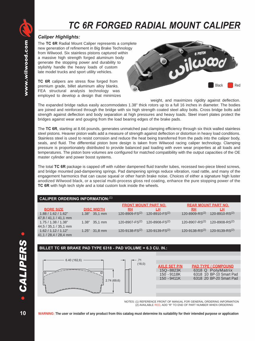
Caliper Highlights:The TC 6R Radial Mount Caliper represents a completenew generation of refinement in Big Brake Technologyfrom Wilwood. Six stainless pistons captured withina massive high strength forged aluminum bodygenerate the stopping power and durability tostylishly handle the heavy loads of customlate model trucks and sport utility vehicles.
TC 6R calipers are stress flow forged frompremium grade, billet aluminum alloy blanks.FEA structural analysis technology wasemployed to develop a design that minimizes
weight, and maximizes rigidity against deflection.The expanded bridge radius easily accommodates 1.38" thick rotors up to a full 16 inches in diameter. The bodiesare joined and reinforced through the bridge with six high strength coated steel alloy bolts. Cross bridge bolts addstrength against deflection and body separation at high pressures and heavy loads. Steel insert plates protect thebridges against wear and gouging from the load bearing edges of the brake pads.
The TC 6R, starting at 8.66 pounds, generates unmatched pad clamping efficiency through six thick walled stainlesssteel pistons. Heavier piston walls add a measure of strength against deflection or distortion in heavy load conditions.Stainless steel is used to resist corrosion and reduce the heat being transferred from the pads into the caliper body,seals, and fluid. The differential piston bore design is taken from Wilwood racing caliper technology. Clampingpressure is proportionately distributed to provide balanced pad loading with even wear properties at all loads andtemperatures. The piston bore volumes are configured for matched compatibility with the output capacities of the OEmaster cylinder and power boost systems.
The total TC 6R package is capped off with rubber dampened fluid transfer tubes, recessed two-piece bleed screws,and bridge mounted pad-dampening springs. Pad dampening springs reduce vibration, road rattle, and many of theengagement harmonics that can cause squeal or other harsh brake noise. Choices of either a signature high lusteranodized Wilwood black, or a special multi-process gloss red coating, enhance the pure stopping power of theTC 6R with high tech style and a total custom look inside the wheels.
NOTES: (1) REFERENCE FRONT OF MANUAL FOR GENERAL ORDERING INFORMATION(2) AVAILABLE RED, ADD “R” TO END OF PART NUMBER WHEN ORDERING
Black Red
2.74 (69,6)
6.40 (162,6) .71
(18,0) AXLE SET P/N PAD TYPE / COMPOUND15Q- 8823K 6318 Q PolyMatrix150 - 9118K 6318 10 BP-10 Smart Pad150 - 9411K 6318 20 BP-20 Smart Pad
BILLET TC 6R BRAKE PAD TYPE 6318 - PAD VOLUME = 6.3 CU. IN.:

2.56 (65,0)
MOUNT
HEIGHT
"D1"
TOP OF FRICTION MATERIAL
AND DISC O.D. TO BE FLUSH
SMALL
PISTON
SMALL
PISTON
.52 (13,2)
13.16 (334,3)
"C"
OVERALL WIDTH
LARGE
PISTON
DISC WIDTH
1.92 (48,8) 1.92 (48,8)
"B"
MOUNT OFFSET
"E"
OUTSIDE RADIUS
8.27 (210,1)
MOUNT CENTER
DISC/WHEEL CENTERLINE
DIMENSIONS "D1" = (DISC DIAMETER/2) - 2.56 (65,0)
NOTE:
RIGHT HAND REAR MOUNT CALIPER SHOWN
INLET FITTING: 1/8-27 NPT
DISC ROTATION
DISC
DIAMETER
16.00 (406,4)
14.00 (355,6)
"E"
OUTSIDE RADIUS
8.81 (223,8)
8.14 (206,8)
"C"
OVERALL WIDTH
5.41 (137,4)
5.29 (134,4)
DISC
WIDTH
1.38 (35,1)
1.25 (31,8)
"B"
MOUNT OFFSET
1.65 (41,9)
1.58 (40,3)
6 PISTON
Brakes are critical safety components, see warnings and disclaimer on page 133
www.wilw
ood.com
11
•C
AL
IPE
RS
•BILLET TC 6R CALIPER, MOUNTING DIMENSIONS:
Radial mount adapter brackets are used in Wilwoodbrake kits to provide a secure and precise method ofattaching the TC 6R caliper to the factory mountbosses on the original spindle. For a list of specificavailable applications, consult the Wilwood Bolt-OnBrake Kit catalog, or visit the kit section of ourwebsite @ www.wilwood.com.
RADIAL CALIPER ADAPTER BRACKETS:
CALIPER SQ RING BLEED SCREW CROSSOVER BRIDGE BRIDGE WEARPART NO. PISTON KIT (6 PK) KIT (4 PK) TUBE KIT (4 PK) BOLT KIT PLATE (EA)
120-8907 200-7528 (1.75”) 130-3084 220-6069 190-9172 230-9171 300-8893 (R/H)200-7518 (1.38”) 300-8894 (L/H)
120-8908 200-7528 (1.75”) 130-3084 220-6069 190-9172 230-9171 300-8893 (R/H)200-7518 (1.38”) 300-8894 (L/H)
120-8909 200-9060 (1.88”) 130-9173 220-6069 190-9172 230-9171 300-8893 (R/H)200-7520 (1.62”) 300-8894 (L/H)
120-8910 200-9060 (1.88”) 130-9173 220-6069 190-9172 230-9171 300-8893 (R/H)200-7520 (1.62”) 300-8894 (L/H)
120-9138 200-7520 (1.62”) 130-5972 220-6069 190-9201 230-9200 300-8893 (R/H)200-8439 (1.12”) 300-8894 (L/H)
120-9139 200-7520 (1.62”) 130-5972 220-6069 190-9201 230-9200 300-8893 (R/H)200-8439 (1.12”) 300-8894 (L/H)
SERVICE PARTS ORDERING INFORMATION:

WARNING: The user or installer of any product from this catalog must determine its suitability for their intended purpose or application
www.wilwood.com
12
•C
AL
IPE
RS
•W6A / W4A RADIAL MOUNT CALIPERS
Caliper Highlights:The W6A forged six piston caliper and W4A four piston caliperdeliver heavy duty stopping power for the road or track. Bothcalipers incorporate race technology into a body design withwidespread adaptability. Radial mounting, two options for pistonvolume, and a rotor diameter ranging from 12.19" to 14.25" givethese calipers the versatility necessary to suit all types of heavyweight braking requirements.
The W6A/W4A body is the product of FEA computer design andstress flow forging technology. FEA technology allows thedesigner to test the prototype in a computer environment to determine theoptimal structural design within the dimensional parameters of the component. Stressflow forging produces a part with the internal grain structure of the metal aligned in the direction of the flow of the body contour. Theresults are a caliper with superior clamping efficiency and ultimate strength against fatigue, stresses, and distortion under load.
These calipers generates big brake clamping force with six or four differential bore stainless steel pistons. Stainless steel is used forits high resistance to corrosion and low thermal conductivity that reduces the heat transfer from the pads. The differential bore patternbalances pad loading to help maintain even pad wear. High temperature bore seals provide long service life and maintain theirresilience to provide positive piston retraction on release. Two options for overall piston volume make it simple to match the caliperswith master cylinder output and rear caliper size for correct bias proportioning.
The performance of theW6A/W4A is enhanced with SRS bridge plates, snap-ring locked pad retainer pins, recessed two-piece bleedscrew assemblies and dampen mounted fluid transfer tubes. SRS bridge plates eliminate all bridge wear caused by pad gouging.The spring-loaded action of the plates also eliminates pad rattle. Snap ring clips lock the pad pins in place to provide positive retentionand allow easy service without caliper removal. The bleed screws are recess mounted for protection against impact and debris. Thefluid tubes are dampen mounted to protect them from fatigue or damage from vibration or debris. Calipers are anodized in high lusterblack to protect from corrosion and maintain their high-tech appearance. The W6A/W4A is also available with a gloss red finish orother custom Wilwood color by order.
NOTES: (1) REFERENCE FRONT OF MANUAL FOR GENERAL ORDERING INFORMATION(2) AVAILABLE RED, ADD “R” TO END OF PART NUMBER WHEN ORDERING. FOR OTHER CUSTOM WILWOOD COLORS, CONTACT THE FACTORY.(3) THESE CALIPERS COME WITH THERMLOCK PISTONS.
.67
(17,0)
2.87 (72,9)
5.87 (149,1)AXLE SET P/N PAD TYPE / COMPOUND15A - 9977K 6617 A PolyMatrix15B - 9978K 6617 B PolyMatrix15H - 9979K 6617 H PolyMatrix150 - 9488K 6617 10 BP-10 Smart Pad150 - 9489K 6617 20 BP-20 Smart Pad150 - 9980K 6617 30 BP-30 Smart Pad
W6A / W4A BRAKE PAD TYPE 6617 - PAD VOLUME = 5.2 CU. IN.:
W6A CALIPER ORDERING INFORMATION:(1)
REAR MOUNT PART NUMBERBORE SIZE DISC WIDTH RH LH
1.75 / 1.38 / 1.38” 1.25” 31,8 mm 120-9398-RS(2) 120-9399-RS(2)44,5 / 35,1 / 35,1 mm1.62 / 1.12 / 1.12” 1.25” 31,8 mm 120-9402-RS(2) 120-9403-RS(2)
41,1 / 28,4 / 28,4 mm1.62 / 1.12 / 1.12” 1.25” 31,8 mm 120-10224-RS(2,3) 120-10225-RS(2,3)
41,1 / 28,4 / 28,4 mm
W4A CALIPER ORDERING INFORMATION:(1)
REAR MOUNT PART NUMBERBORE SIZE DISC WIDTH RH LH1.88 / 1.62” 1.25” 31,8 mm 120-9679-RS(2) 120-9680-RS(2)
47,8 / 41,1 mm1.62 / 1.38” 1.25” 31,8 mm 120-9681-RS(2) 120-9682-RS(2)
41,1 / 35,1 mm
Black Red

7.09 (180,1)MOUNT CENTER
SMALL PISTONW6A ONLY
LARGE PISTONW6A AND W4A
SMALL PISTONW6A AND W4A
DISC ROTATION10.96 (278,4)
8.02 (203,7)OUTSIDE RADIUS
2.09 (53,1)MOUNTHEIGHT
DISC/WHEEL CENTERLINE
TOP OF FRICTION MATERIALAND DISC O.D. TO BE FLUSH
1.25 (31,8)DISC WIDTH
1.82 (46,2)MOUNT OFFSET
5.03 (127,8)
2.48 (63,0) 2.21 (56,1)
DIMENSIONS FOR USE WITHA 14.25 (362,0) X 1.25 (31,8) DISC
NOTE: RIGHT HAND, REAR MOUNTCALIPER SHOWN - INLET FITTING: 1/8-27 NPT
Brakes are critical safety components, see warnings and disclaimer on page 133
www.wilw
ood.com
13
•C
AL
IPE
RS
•W6A / W4A CALIPER, MOUNTING DIMENSIONS:
Radial mount adapter brackets are used in Wilwoodbrake kits to provide a secure and precise method ofattaching the W6A / W4A caliper to the factory mountbosses on the original spindle. For a list of specificavailable applications, consult the Wilwood Bolt-OnBrake Kit catalog, or visit the kit section of ourwebsite @ www.wilwood.com.
RADIAL CALIPER ADAPTER BRACKETS:
CALIPER SQ RING BLEED SCREW CROSSOVER PAD RETAINING BRIDGE WEARPART NO. PISTON KIT (6 PK) KIT (4 PK) TUBE KIT (2 PK) KIT (2 PK) PLATE (EA)
120-9398 200-7531 (1.75”) 130-3084 220-6069 190-9875 180-9874 300-5876200-7516 (1.38”)
120-9399 200-7531 (1.75”) 130-3084 220-6069 190-9875 180-9874 300-5876200-7516 (1.38”)
120-9402 200-7519 (1.62”) 130-5972 220-6069 190-9875 180-9874 300-5876200-7513 (1.12”)
120-9403 200-7519 (1.62”) 130-5972 220-6069 190-9875 180-9874 300-5876200-7513 (1.12”)
120-10224 200-7553 (1.62”) 130-5972 220-6069 190-9875 180-9874 300-5876200-7556 (1.12”)
120-10225 200-7553 (1.62”) 130-5972 220-6069 190-9875 180-9874 300-5876200-7556 (1.12”)
W6A CALIPER SERVICE PARTS ORDERING INFORMATION:
CALIPER SQ RING BLEED SCREW CROSSOVER PAD RETAINER BRIDGE WEARPART NO. PISTON KIT (4 PK) KIT (4 PK) TUBE KIT (2 PK) KIT (2 PK) PLATE (EA)
120-9679 200-7521 (1.88”) 130-5100 220-6069 190-9875 180-9874 300-5876200-7519 (1.62”)
120-9680 200-7521 (1.88”) 130-5100 220-6069 190-9875 180-9874 300-5876200-7519 (1.62”)
120-9681 200-7519 (1.62”) 130-9873 220-6069 190-9875 180-9874 300-5876200-7516 (1.38”)
120-9682 200-7519 (1.62”) 130-9873 220-6069 190-9875 180-9874 300-5876200-7516 (1.38”)
W4A CALIPER SERVICE PARTS ORDERING INFORMATION:

WARNING: The user or installer of any product from this catalog must determine its suitability for their intended purpose or application
www.wilwood.com
14
•C
AL
IPE
RS
•BILLET SUPERLITE SL6R RADIAL MOUNT CALIPERS
NOTES: (1) REFERENCE FRONT OF MANUAL FOR GENERAL ORDERING INFORMATION(2) AVAILABLE IN RED, ADD “R” TO END OF PART NUMBER WHEN ORDERING(3) THESE CALIPERS MAY ALSO BE USED WITH 1.10” THICK ROTORS AND 7416 TYPE 16MM THICK PADSFS = FRONT SIDE MOUNT, RS = REAR SIDE MOUNT, SI = SIDE INLET
Caliper Highlights:The billet SL6R series adds the versatility and convenience of radial mounting to this widely popular caliper group.Radial mounting simplifies adaptation and provides two planes of adjustment for accurate alignment over the disc.These calipers integrate "Big Brake" style with Wilwood's latest technology to generate big stopping power in extremeenvironments over a broad range of vehicle applications.
The key to the superior performance of the SL6R comes from the extremely durable and efficient body design.Starting at 4.84 pounds it is the product of computer generated solid modeling and FEA stress analysis technology.Full length stiffening ribs and a reinforced radial transition from the piston bore housings to the closed end bridgeshas produced the strongest SL caliper bodies ever built. When compared to open bridge calipers that use tube orstand spacers between the body halves, the closed end bridge design is measurably stronger with less separation ordeflection under load. Additional strength and resistance to deflection comes from the four high-strength steel endbridge bolts. A fifth center bridge bolt provides even more overall strength and easy access to the pads without theneed to remove the caliper from the mount.
A unique six-piston differential bore configuration provides balanced loading for even pad wear in sustained high heatenvironments. The standard SL6R calipers feature one-piece stainless steel pistons. Stainless is used for its slowheat transfer properties and high resistance to corrosion. The SL6R/ST models feature Wilwood's exclusiveThermlock pistons. This multi-part piston design creates a highly efficient thermal barrier to further reduce heattransfer from the pads to caliper body, seals, and fluid. Cooler temperatures translate to longer service life and lesschance for heat induced pedal fade.
In addition, each SL6R is equipped with SRS bridge plates. SRS plates eliminate all bridge wear caused by padgouging and extend the service life of the caliper. The spring-loaded action of the SRS plates also eliminates padrattle and dampens the harmonic vibrations that contribute to pad squeal. Two piece bleed screws and dampenedfluid tubes are recess mounted to shield them from track debris and other potential damage sources. Hightemperature, square faced bore seals provide the largest possible sealing area and controlled piston retraction onrelease. The full range of Wilwood pad compounds is available to match the brake response and heat range of anycompetition or sports driving application.
Calipers in this group feature a full width reinforced riboutboard body for maximum strength when caliper to hubor caliper to wheel clearance is not an issue. Thesecalipers are primarily used for asphalt stock cars, roadracing, and other competition applications with small 5on 5 or other OE type lug patterns. The caliper bridgeradius will clear rotors from 11.75" to 13.00" in overalldiameter. Each caliper in this group uses 7420 type20mm thick pads. Specific mounting and body widthdimensions can be found in the chart on page 16.
BILLET SL6R AND SL6R/ST:
SL6R WITH STAINLESS STEEL PISTONS CALIPER ORDERING INFORMATION:(1)
FRONT MOUNT PART NO. REAR MOUNT PART NO.BORE SIZE DISC WIDTH RH LH RH LH
1.62 / 1.12 / 1.12” 1.25” 31,8 mm 120-6115-FS(2) 120-6116-FS(2) 120-6115-RS(2) 120-6116-RS(2)41,1 / 28,4 / 28,4 mm1.62 / 1.12 / 1.12” 1.00” 25,4 mm 120-6113-FS 120-6114-FS 120-6113-RS 120-6114-RS41,1 / 28,4 / 28,4 mm1.62 / 1.12 / 1.12” .81” 20,6 mm 120-6111-FS(3) 120-6112-FS(3) 120-6111-RS(3) 120-6112-RS(3)41,1 / 28,4 / 28,4 mm
Black Red

2.43 (61,7)
.80
(20,3)
4.74 (120,4)
Calipers in this group feature a reduced width outboardbody to provide additional clearance between the caliperface and the wheel or hub. These calipers were originallybuilt for use with wide 5 hubs, but have found their way toOE performance "Big Brake" conversions, road racing,and other close fit wheel applications. The caliper bridgeradius will clear rotors from 11.75" to 13.00" in overalldiameter. Each caliper in this group uses 7420 type 20mmthick pads. Specific mounting and body width dimensionscan be found in the chart on page 16.
Brakes are critical safety components, see warnings and disclaimer on page 133
www.wilw
ood.com
15
•C
AL
IPE
RS
•
AXLE SET P/N PAD TYPE / COMPOUND15A - 5938K 7420 A PolyMatrix15B - 5939K 7420 B PolyMatrix15C - 6853K 7420 C PolyMatrix15E - 6084K 7420 E PolyMatrix15H - 8114K 7420 H PolyMatrix15Q- 6829K 7420 Q PolyMatrix150 - 8854K 7420 10 BP-10 Smart Pad150 - 9416K 7420 20 BP-20 Smart Pad150 - 9864K 7420 30 BP-30 Smart Pad150 - 8323K 7420 SM For Titanium Rotor
SL6R/ST WITH THERMLOCK® PISTONS CALIPER ORDERING INFORMATION:(1)
FRONT MOUNT PART NO. REAR MOUNT PART NO.BORE SIZE DISC WIDTH RH LH RH LH
1.62 / 1.12 / 1.12” 1.25” 31,8 mm 120-6143-FS 120-6144-FS 120-6143-RS 120-6144-RS41,1 / 28,4 / 28,4 mm1.62 / 1.12 / 1.12” 1.25” 31,8 mm — — — 120-6201-SII41,1 / 28,4 / 28,4 mm1.62 / 1.12 / 1.12” 1.00” 25,4 mm 120-6141-FS 120-6142-FS 120-6141-RS 120-6142-RS41,1 / 28,4 / 28,4 mm
BILLET SL6R AND SL6R/ST WITH NARROWED OUTBOARD BODY:
SL6R BRAKE PAD TYPE 7420 - PAD VOLUME = 4.9 CU. IN.:
NARROW SL6R WITH STAINLESS STEEL PISTONS CALIPER ORDERING INFORMATION:(1)
FRONT MOUNT PART NO. REAR MOUNT PART NO.BORE SIZE DISC WIDTH RH LH RH LH
1.62 / 1.12 / 1.12” 1.25” 31,8 mm 120-7761-FS 120-7762-FS 120-7761-RS 120-7762-RS41,1 / 28,4 / 28,4 mm
NARROW SL6R WITH THERMLOCK® PISTONS CALIPER ORDERING INFORMATION:(1)
FRONT MOUNT PART NO. REAR MOUNT PART NO.BORE SIZE DISC WIDTH RH LH RH LH
1.62 / 1.12 / 1.12” 1.25” 31,8 mm 120-6385-FS 120-6386-FS 120-6385-RS 120-6386-RS41,1 / 28,4 / 28,4 mm
NOTES: (1) REFERENCE FRONT OF MANUAL FOR GENERAL ORDERING INFORMATION(2) THESE CALIPERS MAY ALSO BE USED WITH 1.10” THICK ROTORS AND 7416 TYPE 16MM THICK PADSFS = FRONT SIDE MOUNT, RS = REAR SIDE MOUNT, SI = SIDE INLET
Black

DISC
DIAMETER
11.75 (298,5)
12.19 (309,6)
12.72 (323,1)
12.88 (327,2)
13.00 (330,2)
"E"
OUTSIDE RADIUS
6.65 (168,9)
6.81 (173,0)
7.00 (177,8)
7.07 (179,6)
7.13 (181,1)
DISC
WIDTH
1.38 (35,1)
1.25 (31,8)
1.10 (27,9)
1.00 (25,4)
.81 (20,6)
"B"
MOUNT OFFSET
1.80 (45,7)
1.80 (45,7)
1.70 (43,2)
1.70 (43,2)
1.58 (40,1)
NOTE 1: DIMENSION FOR WIDE 5 HUB APPLICATION IS 2.13 (54,1)
NOTE 2: RIGHT HAND REAR MOUNT CALIPER SHOWN.
INLET FITTING: 1/8-27 NPT
RADIAL MOUNT BRACKETS ARE AVAILABLE
DIMENSION "D1" = (DISC DIAMETER/2) - 1.62 (41,1)
1.62 (41,1)
MOUNT HEIGHT
"D1"
DISC WIDTH
"B"
MOUNT OFFSET
1.12 (28,4)
PISTON(S)
1.62 (41,1)
PISTON
5.98 (152,0)
MOUNT CENTER
"E"
OUTSIDE
RADIUS
DISC/WHEEL CENTERLINE
9.44 (239,8)
DISC ROTATION
TOP OF FRICTION MATERIAL AND DISC O.D. TO BE FLUSH
2.35 (59,7)
SEE NOTE 1
2.35 (59,7)
6 PISTON
WARNING: The user or installer of any product from this catalog must determine its suitability for their intended purpose or application
www.wilwood.com
16
•C
AL
IPE
RS
•BILLET SUPERLITE SL6R RADIAL MOUNT CALIPERS
SL6R CALIPER, MOUNTING DIMENSIONS:
CALIPER SQ RING BLEED SCREW CROSSOVER SELF-BLEED BRIDGE BRIDGE WEARPART NO. PISTON KIT (6 PK) KIT (4 PK) TUBE KIT (4 PK) TUBE (EA) BOLT KIT PLATE (EA)
120-6111 200-7519 (1.62”) 130-5972 220-6069 190-5973 — 230-5976 300-5922 (R/H)200-7513 (1.12”) 300-5923 (L/H)
120-6112 200-7519 (1.62”) 130-5972 220-6069 190-5973 — 230-5976 300-5922 (R/H)200-7513 (1.12”) 300-5923 (L/H)
120-6113 200-7519 (1.62”) 130-5972 220-6069 190-5974 — 230-5977 300-5922 (R/H)200-7513 (1.12”) 300-5923 (L/H)
120-6114 200-7519 (1.62”) 130-5972 220-6069 190-5974 — 230-5977 300-5922 (R/H)200-7513 (1.12”) 300-5923 (L/H)
120-6115 200-7519 (1.62”) 130-5972 220-6069 190-5975 190-8310 230-5978 300-5922 (R/H)200-7513 (1.12”) 300-5923 (L/H)
120-6116 200-7519 (1.62”) 130-5972 220-6069 190-5975 190-8310 230-5978 300-5922 (R/H)200-7513 (1.12”) 300-5923 (L/H)
120-6141 200-7553 (1.62”) 130-5972 220-6069 190-5974 — 230-5977 300-5922 (R/H)200-7556 (1.12”) 300-5923 (L/H)
120-6142 200-7553 (1.62”) 130-5972 220-6069 190-5974 — 230-5977 300-5922 (R/H)200-7556 (1.12”) 300-5923 (L/H)
120-6143 200-7553 (1.62”) 130-5972 220-6069 190-5975 190-8310 230-5978 300-5922 (R/H)200-7556 (1.12”) 300-5923 (L/H)
120-6144 200-7553 (1.62”) 130-5972 220-6069 190-5975 190-8310 230-5978 300-5922 (R/H)200-7556 (1.12”) 300-5923 (L/H)
120-6201-SI 200-7553 (1.62”) 130-5972 220-6069 190-5975 190-8310 230-5978 300-5922 (R/H)200-7556 (1.12”) 300-5923 (L/H)
120-6385 200-7553 (1.62”) 130-5972 220-6069 190-5975 190-8310 230-5978 300-5922 (R/H)200-7556 (1.12”) 300-5923 (L/H)
120-6386 200-7553 (1.62”) 130-5972 220-6069 190-5975 190-8310 230-5978 300-5922 (R/H)200-7556 (1.12”) 300-5923 (L/H)
120-7761 200-7519 (1.62”) 130-5972 220-6069 190-5975 190-8310 230-5978 300-5922 (R/H)200-7513 (1.12”) 300-5923 (L/H)
120-7762 200-7519 (1.62”) 130-5972 220-6069 190-5975 190-8310 230-5978 300-5922 (R/H)200-7513 (1.12”) 300-5923 (L/H)
SERVICE PARTS ORDERING INFORMATION:
Wilwood’s unique Thermlock® T2 Short Track Piston isstandard in our STR calipers, for complete details and across-section line drawing, please refer to page 109.
1.62” (41,9 mm) Diameter - Order P/N: 200-75531.12” (28,4 mm) Diameter - Order P/N: 200-7556
THERMLOCK T2 SHORT TRACK PISTON:

Brakes are critical safety components, see warnings and disclaimer on page 133
www.wilw
ood.com
17
•C
AL
IPE
RS
•BILLET SUPERLITE 4R/ST RADIAL MOUNT CALIPER
2.43 (61,7)
.80
(20,3)
4.74 (120,4)
AXLE SET P/N PAD TYPE / COMPOUND15A - 5938K 7420 A PolyMatrix15B - 5939K 7420 B PolyMatrix15C - 6853K 7420 C PolyMatrix15E - 6084K 7420 E PolyMatrix15H - 8114K 7420 H PolyMatrix15Q- 6829K 7420 Q PolyMatrix150 - 8854K 7420 10 BP-10 Smart Pad150 - 9416K 7420 20 BP-20 Smart Pad150 - 9864K 7420 30 BP-30 Smart Pad150 - 8323K 7420 SM For Titanium Rotor
Caliper Highlights:The Billet Superlite 4R/ST is an extremely rigid, four piston, radialmount design that incorporates Wilwood’s latest technology in brakesystem heat management. With its small piston volumes and large padcapacity, it is ideally suited for rear brake applications in severe dutyoval track and road course competition.
The BSL4R/ST body is a product of FEA design and stress analysistechnology. It is configured for use with 1.25" thick rotors and thesubstantial pad volume of the 7420 style brake pad. Starting at 5.32pounds it is the perfect balance between high strength, low deflection, andoverall lightweight. Each caliper is fitted with stainless steel pad load plates toreduce wear and provide the smoothest pad operation. A center bridge bolt adds tooverall caliper strength and gives easy access to the top loaded pads.
Thermlock® T1 pistons are used to minimize the direct heat transfer from the brake pads. Thisconfiguration has been documented to reduce caliper temperatures by more than 30% without the need forfluid recirculation systems. Use EXP 600 Plus racing brake fluid to guarantee trouble free performance in all extreme conditions.
BSLR bracket kits are used to install the BSLR4/ST calipers in place of most 3.50" lug mount calipers. Radial mounting simplifiesservice in the field and the bracket kits provide two planes of adjustment for precise alignment over the disc.
SL4R/ST BRAKE PAD TYPE 7420 - PAD VOLUME = 4.9 CU. IN.:
NOTES: (1) REFERENCE FRONT OF MANUAL FOR GENERAL ORDERING INFORMATION
CALIPER ORDERING INFORMATION:(1)
FRONT MOUNT PART NO. REAR MOUNT PART NO.BORE SIZE DISC WIDTH RH LH RH LH
1.3 /1.12” (44,5/28,4) 1.25” 31,8 mm 120-6541-FS 120-6542-FS 120-6541-RS 120-6542-RS1.25/1.12” (31,8/28,4) 1.25” 31,8 mm 120-6543-FS 120-6544-FS 120-6543-RS 120-6544-RS
Black
DIMENSION "D1" = (DISC DIAMETER/2) - 1.62 (41,1)
DISC
WIDTH
1.25 (31,8)
"B"
MOUNT OFFSET
1.80 (45,7)
NOTE: RIGHT HAND REAR MOUNT CALIPER SHOWN. LEFT HAND CALIPER
HAS BLEED SCREW AND CROSSOVER TUBE REVERSED.
INLET FITTING: 1/8-27 NPT
1.62 (41,1)
MOUNT HEIGHT
"D1"
DISC WIDTH
"B" MOUNT OFFSET
SMALL PISTONLARGE PISTON
5.98 (152,0)
MOUNT CENTER"E"
OUTSIDE
RADIUS DISC/WHEEL CENTERLINE
9.44 (239,8)
DISC ROTATION
TOP OF FRICTION MATERIAL AND DISC O.D. TO BE FLUSH
2.41 (61,2) 2.41 (61,2)
DISC
DIAMETER
11.75 (298,5)
12.19 (309,6)
12.72 (323,1)
12.88 (327,2)
13.00 (330,2)
"E"
OUTSIDE RADIUS
6.65 (168,9)
6.81 (173,0)
7.00 (177,8)
7.07 (179,6)
7.13 (181,1)
SL-4R
BILLET SUPERLITE 4R/ST RADIAL MOUNT CALIPER, MOUNTING DIMENSIONS:
CALIPER SQ RING BLEED SCREW CROSSOVER SELF-BLEED BRIDGE BRIDGE WEARPART NO. PISTON KIT (4 PK) KIT (4 PK) TUBE KIT (4 PK) TUBE (EA) BOLT KIT PLATE (EA)
120-6541 200-7554 (1.38”) 130-7218 220-6069 190-5975 190-8310 230-5976 300-5922 (R/H)200-7556 (1.12”) 300-5923 (L/H)
120-6542 200-7554 (1.38”) 130-7218 220-6069 190-5975 190-8310 230-5976 300-5922 (R/H)200-7556 (1.12”) 300-5923 (L/H)
120-6543 200-7555 (1.25”) 130-7221 220-6069 190-5975 190-8310 230-5976 300-5922 (R/H)200-7556 (1.12”) 300-5923 (L/H)
120-6544 200-7555 (1.25”) 130-7221 220-6069 190-5975 190-8310 230-5976 300-5922 (R/H)200-7556 (1.12”) 300-5923 (L/H)
SERVICE PARTS ORDERING INFORMATION:

WARNING: The user or installer of any product from this catalog must determine its suitability for their intended purpose or application
www.wilwood.com
18
•C
AL
IPE
RS
•BILLET SL6R/4R RADIAL MOUNT CALIPERS FOR 14” DISCS
SL6R CALIPER ORDERING INFORMATION:(1)
FRONT MOUNT PART NO. REAR MOUNT PART NO.BORE SIZE DISC WIDTH RH LH RH LH
1.62 / 1.12 / 1.12” 1.25” 31,8 mm 120-8000-FS(2,3) 120-8001-FS(2,3) 120-8000-RS(2,3) 120-8001-RS(2,3)41,1 / 28,4 / 28,4 mm1.62 / 1.12 / 1.12” 1.10” 27,9 mm 120-8079-FS(2,3) 120-8080-FS(2,3) 120-8079-RS(2,3) 120-8080-RS(2,3)41,1 / 28,4 / 28,4 mm
Caliper Highlights:These specially configured Superlite SL6R/4R narrowbody caliper features an increased bridge radius toallow proper pad alignment and bridge clearance for usewith 13.00" to 14.00" diameter rotors. A special bodydesign is used with 16mm pads to provide the narrowestpossible profile for tight clearance applications. Radialmounting simplifies adaptation and provides two planesof adjustment for accurate alignment over the disc.
A key to the superior performance of the SL6R/4R comesfrom the extremely durable, efficient and lightweight bodydesign. Starting at 4.50 pounds it is the product ofcomputer generated solid modeling and FEA stress analysistechnology. A reinforced radial transition from the piston borehousings to the closed end bridges has produced the strongest SLcaliper bodies ever built. Additional strength and resistance to deflection comes fromthe four high-strength steel end bridge bolts. A fifth center bridge bolt provides even more overall strength and easy access to thepads without the need to remove the caliper from the mount.
SL6R calipers are assembled with one-piece stainless steel pistons and high temperature, square faced bore seals. Stainlesspistons are used for their slow heat transfer properties and high resistance to corrosion. Slow heat transfer reduces the potentialfor heat related pedal fade and increases the service life of the fluid and seals. The high temperature square faced bore sealshave the largest possible sealing area and provide controlled piston retraction on release. The differential bore six-pistonconfiguration distributes the clamping load over the length of the pad to promote even pad wear in the highest temperatureenvironments. This is especially beneficial to vehicles that often realize high temperatures during hard braking.
SL4R calipers come with machined aluminum pistons and rubber dust boots. Aluminum is lightweight with high resistance tocorrosion and fast heat dissipation. The dust boots seal out debris to keep the pistons and caliper bores running smooth. Hightemperature square faced bore seals have the largest possible sealing area and provide controlled piston retraction. Three pistonbore options are available to match the fluid and brake clamping bias requirements of any custom vehicle application.
In addition, each SL6R/4R is equipped with SRS bridge plates. SRS plates eliminate bridge wear caused by pad gouging. Thespring-loaded action of the SRS plates also eliminates pad rattle and dampens pad squeal. Two piece bleed screws anddampened fluid tubes are recess mounted to shield them from track debris and other potential damage sources. A full range ofbrake pad compounds is available to match the brake response and heat range of any competition or sports driving application.
NOTES: (1) REFERENCE FRONT OF MANUAL FOR GENERAL ORDERING INFORMATION(2) AVAILABLE RED, ADD “R” TO END OF PART NUMBER WHEN ORDERING(3) AVAILABLE BLUE, ADD “B” TO END OF PART NUMBER WHEN ORDERING
Blue
2.43 (61,7)
.65
(16,5)
4.74 (120,4) AXLE SET P/N PAD TYPE / COMPOUND15A - 6704K 7416 A PolyMatrix15B - 6705K 7416 B PolyMatrix15E - 6707K 7416 E PolyMatrix15H - 8546K 7416 H PolyMatrix15Q- 6828K 7416 Q PolyMatrix150 - 8855K 7416 10 BP-10 Smart Pad150 - 9415K 7416 20 BP-20 Smart Pad
SL6R / SL4R BRAKE PAD TYPE 7416 - PAD VOLUME = 3.8 CU. IN.:
SL6R Caliper Shown
BORE SIZE DISC WIDTH PART NUMBER1.75” 44,5 mm 1.25” 31,8 mm 120-8071-R/L(2)1.75” 44,5 mm 1.10” 27,9 mm 120-8070-R/L(2)1.38” 35,0 mm 1.25” 31,8 mm 120-8065-R/L1.38” 35,0 mm 1.10” 27,9 mm 120-8064-R/L(2)1.25” 31,8 mm 1.25” 31,8 mm 120-8063-R/L1.25” 31,8 mm 1.10” 27,9 mm 120-8062-R/L(2,3)
SL4R CALIPER ORDERING INFORMATION:(1)
Black Red

PISTON
PISTONSL6R ONLY
PISTON
DISCDIAMETER
11.75 (298,5)12.19 (309,6)12.72 (323,1)12.88 (327,2)13.00 (330,2)14.00 (355,6)
"E"OUTSIDE RADIUS
6.77 (172,0)6.94 (176,3)7.16 (141,1)7.23 (183,6)7.29 (185,2)7.75 (196,8)
DISCWIDTH
1.25 (31,8)1.10 (27,9)
"B"MOUNT OFFSET
1.52 (38,7)1.43 (36,3)
NOTES:1. SL6R = 1.99 (50,5)2. SL6R = 1.79 (45,5)3. SL4R = 2.15 (54,6)4. SL4R = 1.95 (49,5)
DIMENSION "D1" = (DISC DIAMETER/2) - 1.45 (36,8)RIGHT HAND REAR MOUNT CALIPER SHOWN. INLET FITTING: 1/8-27 NPTRADIAL MOUNT BRACKETS ARE AVAILABLE
1.45 (36,8)MOUNT HEIGHT
"D1"5.98 (152,0)MOUNT CENTER
"E"OUTSIDERADIUS
DISC/WHEEL CENTERLINE
9.44 (239,8)DISC ROTATION
TOP OF FRICTIONMATERIAL AND DISC
O.D. TO BE FLUSH
DISC WIDTH
"B" MOUNT OFFSET
NOTE 2, 4NOTE 1, 3
6 PISTON
CALIPER SQ RING BLEED SCREW CROSSOVER BRIDGE BRIDGE WEARPART NO. PISTON KIT (6 PK) KIT (4 PK) TUBE KIT (4 PK) BOLT KIT PLATE (EA)
120-8000 200-7520 (1.62”) 130-5972 220-6069 190-8369 230-7049 300-6595 (R/H)200-8439 (1.12”) 300-6596 (L/H)
120-8001 200-7520 (1.62”) 130-5972 220-6069 190-8369 230-7049 300-6595 (R/H)200-8439 (1.12”) 300-6596 (L/H)
120-8079 200-7520 (1.62”) 130-5972 220-6069 190-7711 230-7710 300-6595 (R/H)200-8439 (1.12”) 300-6596 (L/H)
120-8080 200-7520 (1.62”) 130-5972 220-6069 190-7711 230-7710 300-6595 (R/H)200-8439 (1.12”) 300-6596 (L/H)
Brakes are critical safety components, see warnings and disclaimer on page 133
www.wilw
ood.com
19
•C
AL
IPE
RS
•BILLET NARROW SUPERLITE 6R / SUPERLITE 4R CALIPER, MOUNTING DIMENSIONS:
SL6R CALIPER SERVICE PARTS ORDERING INFORMATION:
Radial mount adapter brackets are used in Wilwoodbrake kits to provide a secure and precise method ofattaching the SL 6R / SL 4R caliper to the factorymount bosses on the original spindle. For a list ofspecific available applications, consult the WilwoodBolt-On Brake Kit catalog, or visit the kit section ofour website @ www.wilwood.com.
RADIAL CALIPER ADAPTER BRACKETS:
CALIPER SQ RING BLEED SCREW CROSSOVER DUST BOOT BRIDGE BRIDGE WEARPART NO. PISTON KIT (4 PK) KIT (4 PK) TUBE KIT (4 PK) (EA) BOLT KIT PLATE (EA)
120-8062 200-7318 (1.25”) 130-2479 220-6069 190-7711 210-7210 230-7710 300-6595 (R/H)300-6596 (L/H)
120-8063 200-7318 (1.25”) 130-2479 220-6069 190-8369 210-7210 230-7049 300-6595 (R/H)300-6596 (L/H)
120-8064 200-7319 (1.38”) 130-2658 220-6069 190-7711 210-7210 230-7710 300-6595 (R/H)300-6596 (L/H)
120-8065 200-7319 (1.38”) 130-2658 220-6069 190-8369 210-7210 230-7049 300-6595 (R/H)300-6596 (L/H)
120-8070 200-7322 (1.75”) 130-2655 220-6069 190-7711 210-7210 230-7710 300-6595 (R/H)300-6596 (L/H)
120-8071 200-7322 (1.75”) 130-2655 220-6069 190-8369 210-7210 230-7049 300-6595 (R/H)300-6596 (L/H)
SL4R CALIPER SERVICE PARTS ORDERING INFORMATION:

WARNING: The user or installer of any product from this catalog must determine its suitability for their intended purpose or application
www.wilwood.com
20
•C
AL
IPE
RS
•BILLET SUPERLITE SL6 LUG MOUNT CALIPERS
Caliper Highlights:The billet SL6 series integrates "Big Brake" style and Wilwood's latest technology into the traditional 3.50" centeredlug mount Superlite caliper category. Each caliper is precision CNC machined from high strength billet into threespecialized configurations that cover a broad range of competition and sports driving applications.
The key to the superior performance of the SL6 comes from the extremely durable, efficient and lightweight bodydesign. Starting at 5.06, pounds it is the product of computer generated solid modeling and FEA stress analysistechnology. Full length stiffening ribs and a reinforced radial transition from the piston bore housings to the closedend bridges have produced the strongest Superlite caliper bodies ever built. When compared to open bridge calipersthat use tube or stand spacers between the body halves, the closed end bridge design is measurably stronger withless separation or deflection under load. Additional strength and resistance to deflection comes from the four high-strength steel end bridge bolts. A fifth center bridge bolt provides even more overall strength and easy access to thepads without the need to remove the caliper from the mount.
A unique six-piston differential bore configuration provides balanced loading for even pad wear in sustained high heatenvironments. The standard SL6 calipers feature one-piece stainless steel pistons. Stainless is used for its slow heattransfer properties and high resistance to corrosion. The SL6/ST models feature Wilwood's exclusive Thermlock®
pistons. This multi-part piston design creates a highly efficient thermal barrier to further reduce heat transfer from thepads to the caliper body, seals, and fluid. Cooler temperatures translate to longer service life and less chance for heatinduced pedal fade.
In addition, each SL6 is equipped with SRS bridge plates. SRS plates eliminate all bridge wear caused by padgouging and extend the service life of the caliper. The spring-loaded action of the SRS plates also eliminates padrattle and dampens the harmonic vibrations that contribute to pad squeal. Two piece bleed screws and dampenedfluid tubes are recess mounted to shield them from track debris and other potential damage sources. Hightemperature, square faced bore seals provide the largest possible sealing area and controlled piston retraction onrelease. The full range of Wilwood pad compounds is available to match the brake response and heat range of anycompetition or sports driving application.
SL6 WITH THERMLOCK® PISTONS CALIPER ORDERING INFORMATION:(1)
FRONT MOUNT PART NO. REAR MOUNT PART NO.BORE SIZE DISC WIDTH RH LH RH LH
1.62 / 1.12 / 1.12” 1.25” 31,8 mm 120-6094-FS 120-6095-FS 120-6094-RS 120-6095-RS41,1 / 28,4 / 28,4 mm
Calipers in this group feature a full width reinforced riboutboard body for maximum strength when caliper tohub or caliper to wheel clearance is not an issue. Thesecalipers are primarily used for asphalt stock cars, roadracing, and other competition applications with small 5on 5 or other OE type lug patterns. The caliper bridgeradius will clear rotors from 11.75" to 13.00" in overalldiameter. Each caliper in this group uses 7420 type20mm thick pads. Specific mounting and body widthdimensions can be found in the chart on page 22.
BILLET SL6 AND SL6/ST:
SL6 WITH STAINLESS STEEL PISTONS CALIPER ORDERING INFORMATION:(1)
FRONT MOUNT PART NO. REAR MOUNT PART NO.BORE SIZE DISC WIDTH RH LH RH LH
1.62 / 1.12 / 1.12” 1.25” 31,8 mm 120-5960-FS 120-5961-FS 120-5960-RS 120-5961-RS41,1 / 28,4 / 28,4 mm1.62 / 1.12 / 1.12” 1.00” 25,4 mm 120-5958-FS 120-5959-FS 120-5958-RS 120-5959-RS41,1 / 28,4 / 28,4 mm1.62 / 1.12 / 1.12” 0.81” 20,6 mm 120-5956-FS 120-5957-FS 120-5956-RS 120-5957-RS41,1 / 28,4 / 28,4 mm
NOTES: (1) REFERENCE FRONT OF MANUAL FOR GENERAL ORDERING INFORMATION • FS = FRONT SIDE MOUNT, RS = REAR SIDE MOUNT, SI = SIDE INLET
Black

Brakes are critical safety components, see warnings and disclaimer on page 133
www.wilw
ood.com
21
•C
AL
IPE
RS
•BILLET SL6 AND SL6/ST WITH NARROWED OUTBOARD BODY:
Calipers in this group feature a reduced width outboardbody to provide additional clearance between the caliperface and the wheel or hub. These calipers were originallybuilt for use with wide 5 hubs, but have found their way toother close fit wheel and hub applications. The caliperbridge radius will clear rotors from 11.75" to 13.00" inoverall diameter. Each caliper in this group uses 7420type 20mm thick pads. Specific mounting and body widthdimensions can be found in the chart on page 22, withdimensional variations outlined in note 1.
NARROWED SL6 WITH STAINLESS STEEL PISTONS CALIPER ORDERING INFORMATION:(1)
FRONT MOUNT PART NO. REAR MOUNT PART NO.BORE SIZE DISC WIDTH RH LH RH LH
1.62 / 1.12 / 1.12” 1.25” 31,8 mm 120-6584-FS 120-6585-FS 120-6584-RS 120-6585-RS41,1 / 28,4 / 28,4 mm
NARROWED BODY SL6 FOR 16MM PADS - POLISHED CALIPER ORDERING INFORMATION:(1)
SL6 WITH THERMLOCK® PISTONS CALIPER ORDERING INFORMATION:(1)
FRONT MOUNT PART NO. REAR MOUNT PART NO.BORE SIZE DISC WIDTH RH LH RH LH
1.62 / 1.12 / 1.12” 1.25” 31,8 mm 120-6387-FS 120-6388-FS 120-6387-RS 120-6388-RS41,1 / 28,4 / 28,4 mm
Calipers in this group have the narrowest profile in theentire SL6 category. They are designed for use with16mm thick 7416 type pads over 1.10" width rotorsbetween 11.75" and 13.00" in diameter. These calipersare primarily used in OE performance "Big Brake"conversion kits and other custom applications withextreme space limitations. Fully polished calipers arealso available for custom show car applications. Specificmounting and body width dimensions can be found inthe chart on page 22, with dimensional variationsoutlined in note 2.
NARROWED BODY SL6 FOR 16MM PADS:
NARROWED BODY SL6 FOR 16MM PADS - BLACK CALIPER ORDERING INFORMATION:(1)
FRONT MOUNT PART NO. REAR MOUNT PART NO.BORE SIZE DISC WIDTH RH LH RH LH
1.62 / 1.12 / 1.12” 1.10” 27,9 mm 120-7228-FS(2) 120-7229-FS(2) 120-7228-RS(2) 120-7229-RS(2)41,1 / 28,4 / 28,4 mm
NOTES: (1) REFERENCE FRONT OF MANUAL FOR GENERAL ORDERING INFORMATION(2) AVAILABLE RED, ADD “R” TO END OF PART NUMBER WHEN ORDERINGFS = FRONT SIDE MOUNT, RS = REAR SIDE MOUNT, SI = SIDE INLET
Black
Polished
REAR MOUNT PART NUMBERBORE SIZE DISC WIDTH RH LH
1.62 / 1.12 / 1.12” 1.10” 27,9 mm 120-7259-RSP 120-7260-RSP41,1 / 28,4 / 28,4 mm
Black Red

WARNING: The user or installer of any product from this catalog must determine its suitability for their intended purpose or application
www.wilwood.com
22
•C
AL
IPE
RS
•BILLET SUPERLITE SL6 LUG MOUNT CALIPERS
2.43 (61,7)
.80
(20,3)
4.74 (120,4) AXLE SET P/N PAD TYPE / COMPOUND15A - 5938K 7420 A PolyMatrix15B - 5939K 7420 B PolyMatrix15C - 6853K 7420 C PolyMatrix15E - 6084K 7420 E PolyMatrix15H - 8114K 7420 H PolyMatrix15Q- 6829K 7420 Q PolyMatrix150 - 8854K 7420 10 BP-10 Smart Pad150 - 9416K 7420 20 BP-20 Smart Pad150 - 9864K 7420 30 BP-30 Smart Pad150 - 8323K 7420 SM For Titanium Rotor
SL6 BRAKE PAD TYPE 7420 - PAD VOLUME = 4.9 CU. IN.:
2.43 (61,7)
.65
(16,5)
4.74 (120,4)AXLE SET P/N PAD TYPE / COMPOUND15A - 6704K 7416 A PolyMatrix15B - 6705K 7416 B PolyMatrix15E - 6707K 7416 E PolyMatrix15H - 8546K 7416 H PolyMatrix15Q- 6828K 7416 Q PolyMatrix150 - 8855K 7416 10 BP-10 Smart Pad150 - 9415K 7416 20 BP-20 Smart Pad
SL6 BRAKE PAD TYPE 7416 - PAD VOLUME = 3.8 CU. IN.:
"A"
BOLT CIRCLE RADIUS
3.49 (88,6)
3.69 (93,7)
3.92 (99,6)
3.99 (101,3)
4.05 (102,9)
DISC
DIAMETER
11.75 (298,5)
12.19 (309,6)
12.72 (323,1)
12.88 (327,2)
13.00 (330,2)
"E"
OUTSIDE RADIUS
6.65 (168,9)
6.81 (173,0)
7.00 (177,8)
7.08 (179,8)
7.13 (181,1)
DISC
WIDTH
1.38 (35,1)
1.25 (31,8)
1.10 (27,9)
1.00 (25,4)
.81 (20,6)
"B"
MOUNT OFFSET
1.54 (39,1)
1.54 (39,1)
1.44 (36,6) Note 3
1.44 (36,6)
1.32 (33,5)
DIMENSION "D1" = (DISC DIAMETER/2) - 2.85 (72,4)
NOTE 1: WIDTH DIMENSION ON NARROW OUTBOARD BODY CALIPER IS 2.13 (54,1)
NOTE 2: WIDTH DIMENSION FOR NARROW BODY CALIPER FOR 16mm PADS IS 1.91 (48,5)
NOTE 3: MOUNT OFFSET DIMENSION FOR NARROW BODY FOR 16mm PADS IS IS 1.23 (31,2)
RIGHT HAND, REAR MOUNT CALIPER SHOWN. INLET FITTING: 1/8-27 NPT.
2.85 (72,4)
MOUNT HEIGHT
"D1"
DISC WIDTH
"B"
MOUNT OFFSET.45 (11,4)
MOUNT HOLE
1.12 (28,4)
PISTON(S)
1.62 (41,1)
PISTON
3.50 (88,9)
MOUNT CENTER
"E"
OUTSIDE
RADIUS
"A"
BOLT CIRCLE
RADIUS
DISC/WHEEL CENTERLINE
9.44 (239,8)
DISC ROTATION
TOP OF FRICTION MATERIAL
AND DISC O.D. TO BE FLUSH2.35 (59,7)See Note 2
2.35 (59,7)See Notes
1 and 2
6 PISTON
SUPERLITE 6 LUG MOUNT CALIPER, MOUNTING DIMENSIONS:

Wilwood’s Thermlock® T1 pistons incorporate a stainless steelshield and coated aluminum shell configuration to provide ahighly efficient thermal barrier between the brake pads and thecaliper body, seals, and fluid. Lower operating temperatureseliminate seal crystallization and localized fluid boiling whileproviding longer caliper service life through decreaseddistortion in the caliper body and piston bores. Thermlock® T1pistons are standard equipment in all “ST” designated calipers.They can also be ordered separately to update any existingstainless steel piston equipped caliper built for 7420 type 20mmpads. Thermlock® T1 pistons are not compatible with thespecial narrow body calipers built for use with the 7416 type16mm pads.
1.62” (41,1 mm) Diameter - Order P/N: 200-75531.12” (28,4 mm) Diameter - Order P/N: 200-7556
FRICTION PAD
LOAD SURFACE
SEAL
CONTACT
SURFACE
INNER SHIELD
THERMLOCK T1 PISTON CROSS-SECTION
OUTER
SHELL
CALIPER SQ RING BLEED SCREW CROSSOVER SELF-BLEED BRIDGE BRIDGE WEARPART NO. PISTON KIT (6 PK) KIT (4 PK) TUBE KIT (4 PK) TUBE (EA) BOLT KIT PLATE (EA)
120-5956 200-7519 (1.62”) 130-5972 220-6069 190-5973 — 230-5976 300-5922 (R/H)200-7513 (1.12”) 300-5923 (L/H)
120-5957 200-7519 (1.62”) 130-5972 220-6069 190-5973 — 230-5976 300-5922 (R/H)200-7513 (1.12”) 300-5923 (L/H)
120-5958 200-7519 (1.62”) 130-5972 220-6069 190-5974 — 230-5977 300-5922 (R/H)200-7513 (1.12”) 300-5923 (L/H)
120-5959 200-7519 (1.62”) 130-5972 220-6069 190-5974 — 230-5977 300-5922 (R/H)200-7513 (1.12”) 300-5923 (L/H)
120-5960 200-7519 (1.62”) 130-5972 220-6069 190-5975 190-8310 230-5978 300-5922 (R/H)200-7513 (1.12”) 300-5923 (L/H)
120-5961 200-7519 (1.62”) 130-5972 220-6069 190-5975 190-8310 230-5978 300-5922 (R/H)200-7513 (1.12”) 300-5923 (L/H)
120-6094 200-7553 (1.62”) 130-5972 220-6069 190-5975 190-8310 230-5978 300-5922 (R/H)200-7556 (1.12”) 300-5923 (L/H)
120-6095 200-7553 (1.62”) 130-5972 220-6069 190-5975 190-8310 230-5978 300-5922 (R/H)200-7556 (1.12”) 300-5923 (L/H)
120-6198-SI 200-7553 (1.62”) 130-5972 220-6069 190-5973 — 230-5976 300-5922 (R/H)200-7556 (1.12”) 300-5923 (L/H)
120-6199-SI 200-7553 (1.62”) 130-5972 220-6069 190-5975 190-8310 230-5978 300-5922 (R/H)200-7556 (1.12”) 300-5923 (L/H)
120-6387 200-7553 (1.62”) 130-5972 220-6069 190-5975 190-8310 230-5978 300-5922 (R/H)200-7556 (1.12”) 300-5923 (L/H)
120-6388 200-7553 (1.62”) 130-5972 220-6069 190-5975 190-8310 230-5978 300-5922 (R/H)200-7556 (1.12”) 300-5923 (L/H)
120-6584 200-7519 (1.62”) 130-5972 220-6069 190-5975 190-8310 230-5978 300-5922 (R/H)200-7513 (1.12”) 300-5923 (L/H)
120-6585 200-7519 (1.62”) 130-5972 220-6069 190-5975 190-8310 230-5978 300-5922 (R/H)200-7513 (1.12”) 300-5923 (L/H)
120-7228 200-7520 (1.62”) 130-5972 220-6069 190-7711 — 230-7710 300-6595 (R/H)200-8439 (1.12”) 300-6596 (L/H)
120-7229 200-7520 (1.62”) 130-5972 220-6069 190-7711 — 230-7710 300-6595 (R/H)200-8439 (1.12”) 300-6596 (L/H)
120-7259 200-7520 (1.62”) 130-5972 220-6069 190-7711 — 230-7709 300-6595 (R/H)200-8439 (1.12”) 300-6596 (L/H)
120-7260 200-7520 (1.62”) 130-5972 220-6069 190-7711 — 230-7709 300-6595 (R/H)200-8439 (1.12”) 300-6596 (L/H)
Brakes are critical safety components, see warnings and disclaimer on page 133
www.wilw
ood.com
23
•C
AL
IPE
RS
•THERMLOCK T1 SHORT TRACK PISTON:
SERVICE PARTS ORDERING INFORMATION:

WARNING: The user or installer of any product from this catalog must determine its suitability for their intended purpose or application
www.wilwood.com
24
•C
AL
IPE
RS
•BILLET SUPERLITE 4 AND 4/ST LUG MOUNT CALIPERS
SUPERLITE 4/ST WITH THERMLOCK® PISTONS CALIPER ORDERING INFORMATION:(1)
FRONT MOUNT PART NO. REAR MOUNT PART NO.BORE SIZE DISC WIDTH RH LH RH LH1.88 / 1.75” 1.25” 31,8 mm 120-7570-FS 120-7571-FS 120-7570-RS 120-7571-RS
47,8 / 44,5 mm
SUPERLITE 4/ST WITH STAINLESS STEEL PISTONS CALIPER ORDERING INFORMATION:(1)
FRONT MOUNT PART NO. REAR MOUNT PART NO.BORE SIZE DISC WIDTH RH LH RH LH1.88 / 1.75” 1.25” 31,8 mm 120-7568-FS 120-7569-FS 120-7568-RS 120-7569-RS
47,8 / 44,5 mm
NOTES: (1) REFERENCE FRONT OF MANUAL FOR GENERAL ORDERING INFORMATION
Caliper Highlights:The billet SL4 and SL4/ST calipers incorporateWilwood's latest technology in a conventional3.50" centered lug mount design, with weightsstarting at 4.94 pounds. This caliper series hasbeen structurally designed for high clampingefficiency and low deflection in a body widthcompatible with all wide 5 and 5 x 5 style hubs. Itis a direct replacement for all other Superlite stylecalipers.
The SL4 series bodies are the products of FEA solidmodeling and stress analysis technology. A reinforced radialtransition between the piston housing body and the solid bridge is combinedwith a full body length reinforcement rib to give this caliper the highest resistance to deflection and separation underload of any Superlite style caliper available. Four high strength steel bridge bolts and a fifth center bridge bolt furtheradd to the superior clamping efficiency while providing easy access to the 7420 style pads.
All SL4 series calipers use a big differential bore four-piston design. The 1.88" / 1.75" piston sizes provide the largesteffective piston clamping area of any model in the Superlite series. The differential bore pattern uses the pressurevariance between the bore sizes to compensate for the natural temperature changes cross the face of the pad andthe natural tendencies for the pad to "self load" on the leading edge. The split balance of the pad loading promoteseven pad wear in the higher temperature applications. Standard SL4 models use one piece stainless steel pistons fortheir low heat transfer properties and their high resistance to corrosion. For the ultimate protection in extremesustained high heat competition, SL4/ST models are equipped with Wilwood's exclusive Thermlock® pistons. Thismulti-part piston assembly provides a highly effective thermal barrier that reduces heat transfer from the pads to thefluid, seals, and caliper body by as much as 30%. Seal life and fluid performance is increased proportionately. Hightemperature square faced seals provide the largest possible sealing surface area with controlled piston retraction onrelease.
Every SL4 and SL4/ST caliper incorporates new and adapted performance features from other Wilwood designs.Each caliper is equipped with replaceable SRS stainless steel bridge wear plates. SRS plates eliminate the bridgewear caused by pad gouging to extend the service life of the caliper. The spring-loaded action of the SRS plateseliminates pad rattle and dampens the vibration harmonics that contribute to pad squeal. The bodies are machinedwith recesses to protect the fluid crossover tubes and bleed screws. The fluid tubes are dampen mounted and twopiece bleed screw assemblies assure reliability in harsh conditions and round out the total performance package. Thefull range of Wilwood brake pad compounds is available in the 7420 type pads to match the brake response and heatrange of any competition application.
Black

"A"
BOLT CIRCLE RADIUS
3.49 (88,6)
3.69 (93,7)
3.92 (99,6)
3.99 (101,3)
4.05 (102,9)
DISC
DIAMETER
11.75 (298,5)
12.19 (309,6)
12.72 (323,1)
12.88 (327,2)
13.00 (330,2)
"E"
OUTSIDE RADIUS
6.65 (168,9)
6.81 (173,0)
7.01 (178,0)
7.08 (179,8)
7.14 (181,4)
DISC
WIDTH
1.25 (31,8)
"B"
MOUNT OFFSET
1.54 (39,1)
DIMENSION "D1" =
(DISC DIAMETER/2) - 2.85 (72,4)
NOTE: RIGHT HAND REAR MOUNT CALIPER SHOWN.
LEFT HAND CALIPER HAS BLEED SCREW
AND CROSSOVER TUBE REVERSED.
INLET FITTING: 1/8-27 NPT
2.85 (72,4)
MOUNT HEIGHT
"D1"
DISC WIDTH
"B"
MOUNT OFFSET
SMALL PISTON
.45 (11,4)
MOUNT HOLE
LARGE PISTON
"E"
OUTSIDE
RADIUS
"A"
BOLT
CIRCLE
DISC/WHEEL CENTERLINE
9.44 (239,8)
DISC ROTATION
3.50 (88,9)
MOUNT CENTER
TOP OF FRICTION MATERIAL
AND DISC O.D. TO BE FLUSH
2.41
(61,2)
2.19
(55,6)
4 PISTON
CALIPER SQ RING BLEED SCREW CROSSOVER SELF-BLEED BRIDGE BRIDGE WEARPART NO. PISTON KIT (4 PK) KIT (4 PK) TUBE KIT (4 PK) TUBE (EA) BOLT KIT PLATE (EA)
120-7568 200-7522 (1.88”) 130-2427 220-6069 190-5975 190-8310 230-5978 300-5922 (R/H)200-7532 (1.75”) 300-5923 (L/H)
120-7569 200-7522 (1.88”) 130-2427 220-6069 190-5975 190-8310 230-5978 300-5922 (R/H)200-7532 (1.75”) 300-5923 (L/H)
120-7570 200-7550 (1.88”) 130-2427 220-6069 190-5975 190-8310 230-5978 300-5922 (R/H)200-7551 (1.75”) 300-5923 (L/H)
120-7571 200-7550 (1.88”) 130-2427 220-6069 190-5975 190-8310 230-5978 300-5922 (R/H)200-7551 (1.75”) 300-5923 (L/H)
Brakes are critical safety components, see warnings and disclaimer on page 133
www.wilw
ood.com
25
•C
AL
IPE
RS
•BILLET SUPERLITE 4 CALIPER, MOUNTING DIMENSIONS:
SERVICE PARTS ORDERING INFORMATION:
2.43 (61,7)
.80
(20,3)
4.74 (120,4) AXLE SET P/N PAD TYPE / COMPOUND15A - 5938K 7420 A PolyMatrix15B - 5939K 7420 B PolyMatrix15C - 6853K 7420 C PolyMatrix15E - 6084K 7420 E PolyMatrix15H - 8114K 7420 H PolyMatrix15Q- 6829K 7420 Q PolyMatrix150 - 8854K 7420 10 BP-10 Smart Pad150 - 9416K 7420 20 BP-20 Smart Pad150 - 9864K 7420 30 BP-30 Smart Pad150 - 8323K 7420 SM For Titanium Rotor
SUPERLITE 4 BRAKE PAD TYPE 7420 - PAD VOLUME = 4.9 CU. IN.:

WARNING: The user or installer of any product from this catalog must determine its suitability for their intended purpose or application
www.wilwood.com
26
•C
AL
IPE
RS
•FORGED BILLET SUPERLITE CALIPER
NOTES: (1) REFERENCE FRONT OF MANUAL FOR GENERAL ORDERING INFORMATION (SI = SIDE INLET)(2) AVAILABLE RED, ADD “RD” TO END OF PART NUMBER WHEN ORDERING
Caliper Highlights:The Superlite caliper series has set the standard formany years in short track, late model, modified andopen wheel competition. It has also enjoyedprominence in a variety of road-race, off-road, rallyand sport driving applications. Starting at 4.40pounds, the Forged Billet Superlite (FSL) is thenewest innovation to this series from Wilwood.New and adaptive technologies have beenapplied providing substantial improvements instrength, fluid volume displacement, and overallperformance.
The most noteworthy feature of this new caliper design is theforging. Each body is stress-flow forged from premium grade aluminumalloy billets. Stress-flow forging re-aligns the metal's internal grain structure to flowwithin the contour of the caliper body. This process eliminates the stresses and interruptionsto the internal grain structure that occur when machining a straight block billet. Simply stated, there isno better way to build a stronger aluminum caliper body.
The FSL body design is a highly efficient product of computer generated solid modeling and stress analysistechnology. Each caliper features closed end bridges with a radial transition to the piston body housings. Theelimination of machined steps and sharp shoulders in this critical area provides a measurable increase in overall bodystrength and resistance to deflection under load. Center bridge bolts replace cotter pins to provide additional supportand allow quick access with positive brake pad retention. Clamping force, structural deflection, and volumedisplacement tests have proven the superior strength and efficiency of the FSL. On-track testing has proven driversatisfaction. The bottom line is better stopping power with less pedal travel.
The superior strength of this innovative new caliper is combined with proven performance features from otherWilwood designs. Each caliper is equipped with Wilwood's replaceable SRS stainless steel bridge plates. SRS plateseliminate the bridge wear caused by pad gouging and extend the service life of the caliper body. The spring-loadingaction of the SRS plates also eliminates pad rattle and dampens the vibration harmonics that contribute to squealunder braking. Other standard Wilwood features include high-temperature, square faced o-ring seals for positivesealing, controlled piston retraction, and long service life in high heat conditions. Stainless steel pistons are used toresist corrosion and retard heat transfer from the pads. Fluid tubes are vibration dampened to resist stress fracturesand reduce damage caused by track debris. Two-piece bleed screw assemblies provide long, reliable service life andare easily replaced if necessary.
Forged Billet Superlite calipers are a direct replacement for all Wilwood Superlite and similar competitive brandcalipers with 3.50" centered mounting tabs. Calipers are available in the popular 1.75", 1.62”, 1.38", 1.25” and 1.12”piston sizes for .81", 1.10" and 1.25" rotor widths. FSL calipers use the same 7420 type bridge bolt brake pad usedin all Superlite 6 piston calipers. The full range of PolyMatrix pad compounds is available to match brake responseand heat range to any application.
BORE SIZE DISC WIDTH PART NUMBER1.75” 44,5 mm 1.25” 31,8 mm 120-7429-R/L1.75” 44,5 mm 1.10” 27,9 mm 120-7476-R/L1.75” 44,5 mm .81” 20,6 mm 120-7430-R/L1.75” 44,5 mm .81” 20,6 mm 120-7430-SI1.62” 41,1 mm 1.25” 31,8 mm 120-8466-R/L1.62” 41,1 mm 1.10 27,9 mm 120-8465-R/L1.62” 41,1 mm .81” 20,6 mm 120-8464-R/L(2)1.38” 35,0 mm 1.25” 31,8 mm 120-7431-R/L1.38” 35,0 mm 1.10” 27,9 mm 120-7477-R/L1.38” 35,0 mm .81” 20,6 mm 120-7432-R/L(2)1.25” 31,8 mm 1.25” 31,8 mm 120-7792-R/L1.25” 31,8 mm .81” 20,6 mm 120-7794-R/L1.12” 28,4 mm 1.25” 31,8 mm 120-8282-R/L1.12” 28,4 mm .81” 20,6 mm 120-8283-R/L
CALIPER ORDERING INFORMATION:(1)
Black Red

"A"
BOLT CIRCLE RADIUS
3.50 (88,9)
3.69 (93,7)
3.92 (99,6)
4.00 (101,6)
4.05 (102,9)
DISC
DIAMETER
11.75 (298,5)
12.19 (309,6)
12.72 (323,1)
12.88 (327,2)
13.00 (330,2)
"E"
OUTSIDE RADIUS
6.69 (169,9)
6.85 (174,0)
7.05 (179,1)
7.12 (180,8)
7.18 (182,4)
DISC
WIDTH
1.25 (31,8)
1.10 (27,9)
.81 (20,6)
"B"
MOUNT OFFSET
1.56 (39,6)
1.46 (37,1)
1.34 (34,0)
DIMENSION "D1" = (DISC DIAMETER/2) - 2.85 (72,4)
NOTE: RIGHT HAND CALIPER SHOWN. LEFT
HAND CALIPER HAS BLEED SCREW
AND CROSSOVER TUBE REVERSED.
INLET FITTING: 1/8-27 NPT
2.85 (72,4)
MOUNT HEIGHT
"D1"
DISC WIDTH
"B"
MOUNT OFFSET
.45 (11,4)
MOUNT HOLE
PISTONPISTON
3.50 (88,9)
MOUNT CENTER
"E"
OUTSIDE
RADIUS
"A"
BOLT CIRCLE
RADIUS
DISC/WHEEL CENTERLINE
9.50 (241,3)
TOP OF FRICTION
MATERIAL AND DISC]
O.D. TO BE FLUSH
2.15
(54,6)
2.15
(54,6)
CALIPER SQ RING BLEED SCREW CROSSOVER SELF BLEED BRIDGE BRIDGE WEARPART NO. PISTON KIT (4 PK) KIT (4 PK) TUBE KIT (4 PK) TUBE (EA) BOLT KIT PLATE-R/L (EA)
120-7429 200-7531 (1.75”) 130-2655 220-6069 190-5975 190-8310 230-7541 300-5922/23120-7430 200-7531 (1.75”) 130-2655 220-6069 190-5973 — 230-7539 300-5922/23120-7431 200-7516 (1.38”) 130-2658 220-6069 190-5975 190-8310 230-7541 300-5922/23120-7432 200-7516 (1.38”) 130-2658 220-6069 190-5973 — 230-7539 300-5922/23120-7476 200-7531 (1.75”) 130-2655 220-6069 190-5974 — 230-7540 300-5922/23120-7477 200-7516 (1.38”) 130-2658 220-6069 190-5974 — 230-7540 300-5922/23120-7792 200-7514 (1.25”) 130-2479 220-6069 190-5975 190-8310 230-7541 300-5922/23120-7794 200-7514 (1.25”) 130-2479 220-6069 190-5973 — 230-7539 300-5922/23120-8282 200-7513 (1.12”) 130-2579 220-6069 190-5975 190-8310 230-7541 300-5922/23120-8283 200-7513 (1.12”) 130-2579 220-6069 190-5973 — 230-7539 300-5922/23120-8464 200-7519 (1.62”) 130-4346 220-6069 190-5973 — 230-7539 300-5922/23120-8465 200-7519 (1.62”) 130-4346 220-6069 190-5974 — 230-7540 300-5922/23120-8466 200-7519 (1.62”) 130-4346 220-6069 190-5975 190-8310 230-7541 300-5922/23
Brakes are critical safety components, see warnings and disclaimer on page 133
www.wilw
ood.com
27
•C
AL
IPE
RS
•FORGED BILLET SUPERLITE CALIPER, MOUNTING DIMENSIONS:
SERVICE PARTS ORDERING INFORMATION:
2.43 (61,7)
.80
(20,3)
4.74 (120,4) AXLE SET P/N PAD TYPE / COMPOUND15A - 5938K 7420 A PolyMatrix15B - 5939K 7420 B PolyMatrix15C - 6853K 7420 C PolyMatrix15E - 6084K 7420 E PolyMatrix15H - 8114K 7420 H PolyMatrix15Q- 6829K 7420 Q PolyMatrix150 - 8854K 7420 10 BP-10 Smart Pad150 - 9416K 7420 20 BP-20 Smart Pad150 - 9864K 7420 30 BP-30 Smart Pad150 - 8323K 7420 SM For Titanium Rotor
FORGED BILLET SUPERLITE BRAKE PAD TYPE 7420 - PAD VOLUME = 4.9 CU. IN.:

WARNING: The user or installer of any product from this catalog must determine its suitability for their intended purpose or application
www.wilwood.com
28
•C
AL
IPE
RS
•FSL4 & FSL4/ST DIFFERENTIAL PISTON BORE CALIPER
NOTES: (1) REFERENCE FRONT OF MANUAL FOR GENERAL ORDERING INFORMATION
Caliper Highlights:The Superlite caliper series once again has acutting-edge performer in the new differential pistonbore version. Differential piston bores compensatefor leading-edge mechanical loading andtemperature variance across the pad face toreduce pad taper wear in sustained hightemperature applications. Thermlock® pistons inthe FSL4/ST and heavy wall stainless steel pistonsin the FSL4 models provide choices for two levelsof protection against conductive heat transfer to theseals, fluid, and caliper body. Both the FSL4 andFSL4/ST start at just 4.40 pounds.
This caliper was designed for maximum structural efficiency utilizingcomputer generated solid modeling and FEA stress analysis design technology.The stress flow forging process aligns the internal grain structure for improved strengthand durability over simple block billet machined components. Full width bridges featuring a radialtransition from the piston housings are combined with center bridge bolts for maximum resistance againstbody deflection and separation under load.
The extreme duty FSL4/ST caliper model features Thermlock® pistons for the highest degree of protection againstconductive heat transfer from the pads to the fluid, seals, and body. Average caliper temperatures are reduced by25% over stainless pistons. The standard duty FSL4 model is equipped with the industry’s heaviest wall stainlesssteel pistons. These pistons eliminate high-pressure deflection while providing full resistance to corrosion and slowerheat transfer over common steel or aluminum pistons.
The superior strength of this innovative new caliper is combined with proven performance features from otherWilwood designs. Each caliper is equipped with Wilwood's replaceable SRS stainless steel bridge plates. SRS plateseliminate the bridge wear caused by pad gouging and extend the service life of the caliper body. The spring-loadingaction of the SRS plates also eliminates pad rattle and dampens the vibration harmonics that contribute to squealunder braking. Other standard Wilwood features include high-temperature, square faced piston seals which providea full contact sealing surface and maintain their resilience through long service cycles for effective and controlledpiston retraction. Fluid transfer tubes are dampened and recess mounted to eliminate fatigue from vibration whileadding protection against damage from track or road born debris. Center bridge bolts provide positive pad retentionwith easy access for service without caliper removal. Two-piece bleed screw assemblies provide long, reliableservice life and are easily replaced if necessary.
Forged Billet Superlite differential piston bore calipers are a direct replacement for all Wilwood Superlite and similarcompetitive brand calipers with 3.50" centered mounting tabs. Calipers are available in the popular 1.88/1.75" pistonsizes for .81", and 1.25" rotor widths. FSL4/ST calipers use the same 7420 type bridge bolt brake pad used in allSuperlite 6 piston calipers. The full range of PolyMatrix and Wilwood BP series pad compounds are available tomatch brake response and heat range to any application.
FSL4 WITH STAINLESS STEEL PISTONS CALIPER ORDERING INFORMATION:(1)
Black
REAR MOUNT PART NO.BORE SIZE DISC WIDTH RH LH1.88 / 1.75” 1.25” 31,8 mm 120-9575-RS 120-9576-RS
47,8 / 44,5 mm1.88 / 1.75” 0.81” 20,6 mm 120-9573-RS 120-9574-RS
47,8 / 44,5 mm
FSL4 WITH THERMLOCK® PISTONS CALIPER ORDERING INFORMATION:(1)
REAR MOUNT PART NO.BORE SIZE DISC WIDTH RH LH1.88 / 1.75” 1.25” 31,8 mm 120-9579-RS 120-9580-RS
47,8 / 44,5 mm1.88 / 1.75” 0.81” 20,6 mm 120-9577-RS 120-9578-RS
47,8 / 44,5 mm

"A"
BOLT CIRCLE RADIUS
3.50 (88,9)
3.69 (93,7)
3.92 (99,6)
4.00 (101,6)
4.05 (102,9)
DISC
DIAMETER
11.75 (298,5)
12.19 (309,6)
12.72 (323,1)
12.88 (327,2)
13.00 (330,2)
"E"
OUTSIDE RADIUS
6.69 (169,9)
6.85 (174,0)
7.05 (179,1)
7.12 (180,8)
7.18 (182,4)
DISC
WIDTH
1.25 (31,8)
1.10 (27,9)
.81 (20,6)
"B"
MOUNT OFFSET
1.56 (39,6)
1.46 (37,1)
1.34 (34,0)
DIMENSION "D1" = (DISC DIAMETER/2) - 2.85 (72,4)
NOTE: RIGHT HAND CALIPER SHOWN. LEFT
HAND CALIPER HAS BLEED SCREW
AND CROSSOVER TUBE REVERSED.
INLET FITTING: 1/8-27 NPT
2.85 (72,4)
MOUNT HEIGHT
"D1"
DISC WIDTH
"B"
MOUNT OFFSET
.45 (11,4)
MOUNT HOLE
PISTONPISTON
3.50 (88,9)
MOUNT CENTER
"E"
OUTSIDE
RADIUS
"A"
BOLT CIRCLE
RADIUS
DISC/WHEEL CENTERLINE
9.50 (241,3)
TOP OF FRICTION
MATERIAL AND DISC]
O.D. TO BE FLUSH
2.15
(54,6)
2.15
(54,6)
Brakes are critical safety components, see warnings and disclaimer on page 133
www.wilw
ood.com
29
•C
AL
IPE
RS
•FORGED BILLET SUPERLITE 4 CALIPER, MOUNTING DIMENSIONS:
2.43 (61,7)
.80
(20,3)
4.74 (120,4)AXLE SET P/N PAD TYPE / COMPOUND15A - 5938K 7420 A PolyMatrix15B - 5939K 7420 B PolyMatrix15C - 6853K 7420 C PolyMatrix15E - 6084K 7420 E PolyMatrix15H - 8114K 7420 H PolyMatrix15Q- 6829K 7420 Q PolyMatrix150 - 8854K 7420 10 BP-10 Smart Pad150 - 9416K 7420 20 BP-20 Smart Pad150 - 9864K 7420 30 BP-30 Smart Pad150 - 8323K 7420 SM For Titanium Rotor
FORGED BILLET SUPERLITE 4 BRAKE PAD TYPE 7420 - PAD VOLUME = 4.9 CU. IN.:
CALIPER SQ RING BLEED SCREW CROSSOVER SELF-BLEED BRIDGE BRIDGE WEARPART NO. PISTON KIT (4 PK) KIT (4 PK) TUBE KIT (4 PK) TUBE (EA) BOLT KIT PLATE (EA)
120-9573 200-7521 (1.88”) 130-2427 220-6069 190-5973 — 230-7539 300-5922 (R/H)200-7531 (1.75”) 300-5923 (L/H)
120-9574 200-7521 (1.88”) 130-2427 220-6069 190-5973 — 230-7539 300-5922 (R/H)200-7531 (1.75”) 300-5923 (L/H)
120-9575 200-7521 (1.88”) 130-2427 220-6069 190-5975 190-8310 230-7541 300-5922 (R/H)200-7531 (1.75”) 300-5923 (L/H)
120-9576 200-7521 (1.88”) 130-2427 220-6069 190-5975 190-8310 230-7541 300-5922 (R/H)200-7531 (1.75”) 300-5923 (L/H)
120-9577 200-7550 (1.88”) 130-2427 220-6069 190-5973 — 230-7539 300-5922 (R/H)200-7551 (1.75”) 300-5923 (L/H)
120-9578 200-7550 (1.88”) 130-2427 220-6069 190-5973 — 230-7539 300-5922 (R/H)200-7551 (1.75”) 300-5923 (L/H)
120-9579 200-7550 (1.88”) 130-2427 220-6069 190-5975 190-8310 230-7541 300-5922 (R/H)200-7551 (1.75”) 300-5923 (L/H)
120-9580 200-7550 (1.75”) 130-2427 220-6069 190-5975 190-8310 230-7541 300-5922 (R/H)200-7551 (1.75”) 300-5923 (L/H)
SERVICE PARTS ORDERING INFORMATION:

WARNING: The user or installer of any product from this catalog must determine its suitability for their intended purpose or application
www.wilwood.com
29a
•C
AL
IPE
RS
•D8-4 CALIPERS
Caliper Highlights:The D8-4 front and rear calipers are a direct bolt-on replacement for the factory original calipers onall 1965-82 Chevrolet Corvette's. Forged billetaluminum bodies, stainless steel pistons, andcompetition style high-temperature seals put anend to the rust, bore pitting, and seal failures thatplague the OE caliper design. D8-4 calipersprovide low-maintenance performance for theSunday afternoon driver, and a huge weightsavings with high temperature reliability for the tracks.
D8-4 calipers mount in the stock location over stock rotors, and use theoriginal style OE D8 brake pads. D8-4 calipers can be used with any wheelthat clears the OE calipers. The factory piston sizes were duplicated tomaintain the original front to rear brake bias and use of the OE master cylinder.Only the flex lines that connect the caliper with the hard line fittings on the chassisneed to be replaced to install the D8-4 on any car.
D8-4 forged billet aluminum caliper bodies are the product of Wilwood’s in-house FEA design and 3-D modelingtechnology. With its unyielding strength and superior piston design, the D8-4 generates positive pedal response andhigh clamping efficiency with a substantial weight savings over the OE calipers. As compared to the individual weightof 13.2 pounds each for the OE calipers, a full set of D8-4 calipers reduces unsprung suspension weight by 29pounds. Base model calipers feature a natural aluminum finish protected by a durable clear coat anodizing. Glossred, black, and polished calipers are also available for custom and show applications.
Forged billet aluminum calipers with stainless steel pistons and high temperature seals eliminate the rust, borecorrosion, and seal failures that are common to the OE caliper design. At the track, the stainless pistons delay theheat transfer from the pads while the aluminum calipers dissipate the heat quicker than the OE cast iron calipers.Cooler operating temperatures translate into longer service life, regardless of the driving environment. Each caliperalso uses stainless SRS bridge plates to reduce wear from pad gouging at the caliper bridge. The spring-loadedaction of the SRS plates also reduces noise by eliminating pad rattle and dampening the engagement harmonics thatcan contribute to pad squeal. The D8-4 can be conveniently run on standard OE replacements pads, or fine-tuned todriving conditions with one of the five Wilwood performance compound formulas.
PolishedBlack Red
NOTES: (1) REFERENCE FRONT OF MANUAL FOR GENERAL ORDERING INFORMATION(2) AVAILABLE RED, ADD “RD” TO END OF PART NUMBER WHEN ORDERING(3) AVAILABLE BLACK, ADD “BK” TO END OF PART NUMBER WHEN ORDERING(4) AVAILABLE POLISHED, ADD “P” TOEND OF PART NUMBER WHEN ORDERING
BORE SIZE DISC WIDTH PART NUMBER1.88” 47,8 mm 1.25” 31,8 mm 120-10525(2,3,4)
D8-4 FRONT CALIPER ORDERING INFORMATION:(1)
BORE SIZE DISC WIDTH PART NUMBER1.38” 35,1 mm 1.25” 31,8 mm 120-10526(2,3,4)
D8-4 REAR CALIPER ORDERING INFORMATION:(1)

5.84 (148,3)
DISC WIDTH1.25 (31,8)
2.30 (58,3)
MOUNTINGSURFACE
MOUNT OFFSET1.70 (43,2)
10.21 (259,3)
1.83 (46,5)MOUNTHEIGHT
7.00 (177,8)MOUNT CENTER
TOP OF FRICTIONMATERIAL AND DISC
O.D. TO BE FLUSH
DISC/WHEEL CENTERLINE
NOTE: DIMENSIONS FOR USE WITH 1965-82 STOCK FRONT CORVETTE ROTOR, 11.75 (298,5) X 1.25 (31,8)INLET FITTING: 1/8-27 NPT
4.02 (102,1)
7/16-20 UNF-2BTHD THRUMOUNT HOLE
7.00 (177,8)OUTSIDE RADIUS
Brakes are critical safety components, see warnings and disclaimer on page 133
www.wilw
ood.com
29b
•C
AL
IPE
RS
•D8-4 FRONT CALIPER, MOUNTING DIMENSIONS:
5.84 (148,3)
DISC WIDTH
1.25 (31,8)
2.30 (58,3)
MOUNTING
SURFACE
MOUNT OFFSET
1.30 (33,0)
10.21 (259,3)
2.99 (75,9)
MOUNT
HEIGHT
5.16 (131,1)
MOUNT CENTER
.47 (11,9)
MOUNT HOLE
TOP OF FRICTION
MATERIAL AND DISC
O.D. TO BE FLUSH
DISC/WHEEL CENTERLINE
NOTE: DIMENSIONS FOR USE WITH 1965-82 STOCK REAR CORVETTE ROTOR, 11.75 (298,5) X 1.25 (31,8)
INLET FITTING: 1/8-27 NPT
2.86 (72,6)
7.00 (177,8)
OUTSIDE RADIUS
D8-4 REAR CALIPER, MOUNTING DIMENSIONS:
2.98 (75,7)
.49
(12,3)6.21 (157,7) AXLE SET P/N PAD TYPE / COMPOUND
15A - 6202K D8 A PolyMatrix15E - 8300K D8 E PolyMatrix15Q- 8623K D8 Q PolyMatrix150 - 10546K D8 10 BP-10 Smart Pad150 - 10547K D8 20 BP-20 Smart Pad
D8-4 BRAKE PAD TYPE D8 - PAD VOLUME = 3.9 CU. IN.:
CALIPER SQ RING BLEED SCREW BODY SEAL BRIDGE WEAR PAD RETAINERPART NO. PISTON (EA) KIT (4 PK) (EA) PLATE (EA) CLIP PIN (EA)120-10525 200-7521 (1.88”) 210-5445 220-0627 210-2582 300-10523 310-3634120-10526 200-7516 (1.38”) 210-5442 220-0627 210-2582 300-10523 310-3634
SERVICE PARTS ORDERING INFORMATION:

1.83 (46,5)
3.93 (99,8) .79 (20,1)
WARNING: The user or installer of any product from this catalog must determine its suitability for their intended purpose or application
www.wilwood.com
30
•C
AL
IPE
RS
•IR-GT4R RADIAL MOUNT CALIPER
AXLE SET P/N PAD TYPE / COMPOUND15A - 5772K 7620 A PolyMatrix15C - 4721K 7620 C PolyMatrix15H - 8112K 7620 H PolyMatrix150 - 4717K 7620 Rapco Pad
(.34”Thick)
Caliper Highlights:The IR-GT4R Radial Mount Caliper is a rigid, lightweight, four pistonradial mount design. With smaller piston volumes and thick padcapability, it is suited for a variety of rear brake applications.
The body is a product of FEA design and stress analysis technology. Thefully CNC machined billet body features a closed bridge with grade 8though bolts. Starting at 2.66 pounds it is the perfect balance betweenstrength, low deflection, and lightweight. Caliper is fitted with steel padload plates to reduce wear and provide smooth pad operation. A centerbridge bolt adds strength and gives easy access to the top loaded pads.
PolyMatrix pads are available in several compounds to match brake torque andheat requirement to any competition application.
Stainless steel pistons are used for their slow heat transfer properties and high corrosion resistance. Forextreme heat conditions, the IR-GT4R can be fitted with Wilwood’s exclusive design. Using EXP 600 Plus racingbrake fluid will guarantee the best performance in all conditions.
Bracket kits are used to install the calipers in place of most 3.50" lug mount calipers. Radial mounting simplifies service and the bracket kitsprovide two planes of adjustment for precise alignment over the disc. Bracket kits include the radial mount bracket, studs, locknuts, and caliperalignment shims.
CALIPER ORDERING INFORMATION:(1, 2, 3)
FRONT MOUNT PART NUMBERBORE SIZE DISC WIDTH RH LH
1.38 / 1.12” (35,1 / 28,4 mm) 1.25” 31,8 mm 120-6604 120-66051.25 / 1.00” (31,8 / 25,4 mm) 1.25” 31,8 mm 120-6606 120-6607
NOTES: (1) REFERENCE FRONT OF MANUAL FOR GENERAL ORDERING INFORMATION(2) CALIPERS CAN BE CONVERTED FOR REAR MOUNTING BY EXCHANGING THE POSITION OF THE BLEED SCREWS AND PIPE PLUGS(3) USE RADIAL MOUNT CALIPER BRACKET PART NUMBER 250-6625 FOR MOUNTING TO 3.50” BOLT SPACING AXLE MOUNTS
IR-GT4R BRAKE PAD TYPE 7620 - PAD VOLUME = 3.5 CU. IN.:
Black
SMALL
PISTON
LARGE
PISTON
7.01 (178,0)
4.85 (123,2)
DISC / WHEEL CENTERLINE
"E"
OUTSIDE
RADIUS
1.25 (31,8)
MOUNT
HEIGHT
TOP OF FRICTION
MATERIAL AND DISC
O.D. TO BE FLUSH
4.75 (120,7)
MOUNT CENTER "B"
MOUNT OFFSET
DISC
WIDTH
2.11 (53,6) 2.11 (53,6)
DISC
DIAMETER
12.19 (309,6)
"E"
OUTSIDE RADIUS
6.92 (175,8)
DISC
WIDTH
1.25 (31,8)
"B"
MOUNT OFFSET
1.99 (50,5)
1/8-27 NPT
ROTATION
IR-GT 4R
DISC ROTATION
IR-GT4R RADIAL MOUNT CALIPER, MOUNTING DIMENSIONS:
CALIPER SQ RING BLEED SCREW BODY BRIDGE WEARPART NO. PISTON KIT (4 PK) KIT (4 PK) SEAL (EA) PLATE (EA)
120-6604 200-7516 (1.38”) 130-7218 220-0627 210-2582 300-5066 (R/H)200-7513 (1.12”) 300-5067 (L/H)
120-6605 200-7516 (1.38”) 130-7218 220-0627 210-2582 300-5066 (R/H)200-7513 (1.12”) 300-5067 (L/H)
120-6606 200-4655 (1.25”) 130-7219 220-0627 210-2582 300-5066 (R/H)200-4657 (1.00”) 300-5067 (L/H)
120-6607 200-4655 (1.25”) 130-7219 220-0627 210-2582 300-5066 (R/H)200-4657 (1.00”) 300-5067 (L/H)
SERVICE PARTS ORDERING INFORMATION:
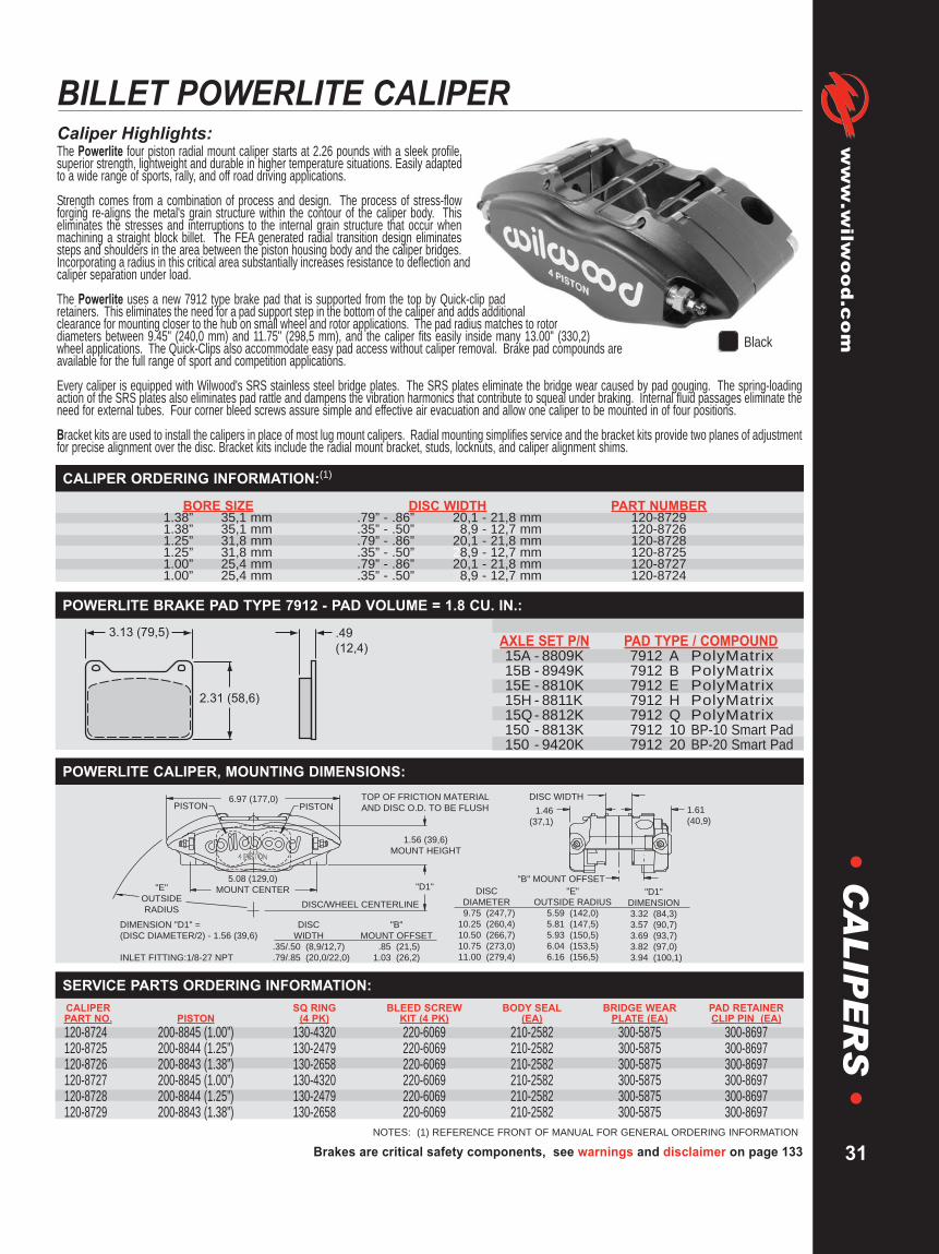
Brakes are critical safety components, see warnings and disclaimer on page 133
www.wilw
ood.com
31
•C
AL
IPE
RS
•BILLET POWERLITE CALIPERCaliper Highlights:The Powerlite four piston radial mount caliper starts at 2.26 pounds with a sleek profile,superior strength, lightweight and durable in higher temperature situations. Easily adaptedto a wide range of sports, rally, and off road driving applications.
Strength comes from a combination of process and design. The process of stress-flowforging re-aligns the metal's grain structure within the contour of the caliper body. Thiseliminates the stresses and interruptions to the internal grain structure that occur whenmachining a straight block billet. The FEA generated radial transition design eliminatessteps and shoulders in the area between the piston housing body and the caliper bridges.Incorporating a radius in this critical area substantially increases resistance to deflection andcaliper separation under load.
The Powerlite uses a new 7912 type brake pad that is supported from the top by Quick-clip padretainers. This eliminates the need for a pad support step in the bottom of the caliper and adds additionalclearance for mounting closer to the hub on small wheel and rotor applications. The pad radius matches to rotordiameters between 9.45" (240,0 mm) and 11.75" (298,5 mm), and the caliper fits easily inside many 13.00" (330,2)wheel applications. The Quick-Clips also accommodate easy pad access without caliper removal. Brake pad compounds areavailable for the full range of sport and competition applications.
Every caliper is equipped with Wilwood's SRS stainless steel bridge plates. The SRS plates eliminate the bridge wear caused by pad gouging. The spring-loadingaction of the SRS plates also eliminates pad rattle and dampens the vibration harmonics that contribute to squeal under braking. Internal fluid passages eliminate theneed for external tubes. Four corner bleed screws assure simple and effective air evacuation and allow one caliper to be mounted in of four positions.
Bracket kits are used to install the calipers in place of most lug mount calipers. Radial mounting simplifies service and the bracket kits provide two planes of adjustmentfor precise alignment over the disc. Bracket kits include the radial mount bracket, studs, locknuts, and caliper alignment shims.
NOTES: (1) REFERENCE FRONT OF MANUAL FOR GENERAL ORDERING INFORMATION
BORE SIZE DISC WIDTH PART NUMBER1.38” 35,1 mm .79” - .86” 20,1 - 21,8 mm 120-87291.38” 35,1 mm .35” - .50” 28,9 - 12,7 mm 120-87261.25” 31,8 mm .79” - .86” 20,1 - 21,8 mm 120-87281.25” 31,8 mm .35” - .50” 28,9 - 12,7 mm 120-87251.00” 25,4 mm .79” - .86” 20,1 - 21,8 mm 120-87271.00” 25,4 mm .35” - .50” 28,9 - 12,7 mm 120-8724
CALIPER ORDERING INFORMATION:(1)
Black
2.31 (58,6)
3.13 (79,5) .49
(12,4)AXLE SET P/N PAD TYPE / COMPOUND15A - 8809K 7912 A PolyMatrix15B - 8949K 7912 B PolyMatrix15E - 8810K 7912 E PolyMatrix15H - 8811K 7912 H PolyMatrix15Q- 8812K 7912 Q PolyMatrix150 - 8813K 7912 10 BP-10 Smart Pad150 - 9420K 7912 20 BP-20 Smart Pad
POWERLITE BRAKE PAD TYPE 7912 - PAD VOLUME = 1.8 CU. IN.:
"D1"
6.97 (177,0)PISTONPISTON
1.46
(37,1)
1.61
(40,9)
1.56 (39,6)
MOUNT HEIGHT
DISC WIDTH
"B" MOUNT OFFSET5.08 (129,0)
MOUNT CENTER"E"
OUTSIDE
RADIUSDISC/WHEEL CENTERLINE
TOP OF FRICTION MATERIAL
AND DISC O.D. TO BE FLUSH
DIMENSION "D1" =
(DISC DIAMETER/2) - 1.56 (39,6)
INLET FITTING:1/8-27 NPT
DISC
DIAMETER
9.75 (247,7)
10.25 (260,4)
10.50 (266,7)
10.75 (273,0)
11.00 (279,4)
"E"
OUTSIDE RADIUS
5.59 (142,0)
5.81 (147,5)
5.93 (150,5)
6.04 (153,5)
6.16 (156,5)
"D1"
DIMENSION
3.32 (84,3)
3.57 (90,7)
3.69 (93,7)
3.82 (97,0)
3.94 (100,1)
DISC
WIDTH
.35/.50 (8,9/12,7)
.79/.85 (20,0/22,0)
"B"
MOUNT OFFSET
.85 (21,5)
1.03 (26,2)
POWERLITE CALIPER, MOUNTING DIMENSIONS:
CALIPER SQ RING BLEED SCREW BODY SEAL BRIDGE WEAR PAD RETAINERPART NO. PISTON (4 PK) KIT (4 PK) (EA) PLATE (EA) CLIP PIN (EA)120-8724 200-8845 (1.00”) 130-4320 220-6069 210-2582 300-5875 300-8697120-8725 200-8844 (1.25”) 130-2479 220-6069 210-2582 300-5875 300-8697120-8726 200-8843 (1.38”) 130-2658 220-6069 210-2582 300-5875 300-8697120-8727 200-8845 (1.00”) 130-4320 220-6069 210-2582 300-5875 300-8697120-8728 200-8844 (1.25”) 130-2479 220-6069 210-2582 300-5875 300-8697120-8729 200-8843 (1.38”) 130-2658 220-6069 210-2582 300-5875 300-8697
SERVICE PARTS ORDERING INFORMATION:

WARNING: The user or installer of any product from this catalog must determine its suitability for their intended purpose or application
www.wilwood.com
32
•C
AL
IPE
RS
•DYNAPRO FORGED BILLET RADIAL MOUNT CALIPERS
Caliper Highlights:DynaPro four piston radial mount calipers combine pure race technologywith a new generation of Wilwood performance enhancements. TheDynaPro combines the versatility of radial mounting with a sleek profile,superior strength, and extreme durability in adverse conditions. With anoverall weight as light as 3.58 pounds, the DynaPro has become a favoredchoice for a broad range of sports, rally, and off-road driving applications.
The strength of the DynaPro is a combination of process and design. Theprocess of stess-flow forging re-aligns the internal grain structure of themetal to flow within the contour of the caliper body. This produces a partwith superior strength over machined block billet parts or castings. The FEAgenerated body design features a radial transition between the piston bores andcaliper bridges. This eliminates macined steps and shoulders in this critical strengtharea and substantially increases the resistance against deflection and body separationunder high load. Structural deflection and volume displacement testing have proven theefficiency of this innovative design. The bottom line is a firm pedal with outstanding stoppingpower.
The DynaPro is available in four configurations. Standard calipers for rotors up to 12.19” feature dust-booted aluminum pistons for maximum protection against track or road born debris in low to intermediatetemperature applications. A long radius version is available to accommodate rotors up to 13.00”. Competition models use heavy wall stainless pistonsto provide addition protection against corrosion and heat transfer from the pads. All DyanPro calipers can also be optioned with Thermlock pistons formaximum thermal protection in sustained high-heat applications. Optional side inlet calipers are available to simplify plumbing with inboard mountedbrakes on live axles and independent suspension rears.
DynaPro calipers use type 7816 pads that are supported from the top by Quick-Clip pad retainers. Quick-Clips allow fast access to the pads for servicewithout the need to dismount the caliper. The Quick-Clip design also allows additional inside radial clearance between the caliper body and the lug hubby eliminating the bottom pad support feet found on other caliper models. Side inlet DynaPros use additionally fortified bridge bolts in place of the Quick-Clips for the ultimate in secure pad retention within high load environments on sprint cars and other extreme duty applications.
The DynaPro incorporates other exclusive Wilwood performance enhancements. Stainless SRS bridge plates eliminate caliper bridge wear from padgouging while dampening noise and vibration during engagement. Internal fluid passages eliminate the need for external crossover tubes and fourcorner bleed screws allow effective gas evacuation regardless of mounting location.
NOTES: (1) REFERENCE FRONT OF MANUAL FOR GENERAL ORDERING INFORMATION(2) AVAILABLE RED, ADD “RD” TO END OF PART NUMBER WHEN ORDERING
BORE SIZE DISC WIDTH PART NUMBER1.75” 44,5 mm 1.00” 25,4 mm 120-85451.75” 44,5 mm .81” 20,6 mm 120-85441.75” 44,5 mm .81” 20,6 mm 120-8544-SI1.75” 44,5 mm .38” - .50” 9,7 - 12,7 mm 120-85431.75” 44,5 mm .38” - .50” 9,7 - 12,7 mm 120-8543-SI1.62” 41,1 mm 1.00” 25,4 mm 120-85421.62” 41,1 mm .81” 20,6 mm 120-85411.62” 41,1 mm .38” - .50” 9,7 - 12,7 mm 120-85401.38” 35,1 mm 1.00” 25,4 mm 120-85391.38” 35,1 mm .81” 20,6 mm 120-85381.38” 35,1 mm .38” - .50” 9,7 - 12,7 mm 120-85371.25” 31,8 mm 1.00” 25,4 mm 120-85361.25” 31,8 mm .81” 20,6 mm 120-85351.25” 31,8 mm .38” - .50” 9,7 - 12,7 mm 120-8534
CALIPER ORDERING INFORMATION, DPR COMPETITION CALIPERS W/STAINLESS STEEL PISTONS:(1)
BORE SIZE DISC WIDTH PART NUMBER1.75” 44,5 mm 1.00” 25,4 mm 120-73811.75” 44,5 mm .81” 20,6 mm 120-73801.75” 44,5 mm .38” - .50” 9,7 - 12,7 mm 120-77261.62” 41,1 mm 1.00” 25,4 mm 120-7379(2)1.62” 41,1 mm .81” 20,6 mm 120-7378(2)1.62” 41,1 mm .38” - .50” 9,7 - 12,7 mm 120-77251.50” 38,1 mm 1.00” 25,4 mm 120-73281.50” 38,1 mm .81” 20,6 mm 120-7327(2)1.50” 38,1 mm .38” - .50” 9,7 - 12,7 mm 120-77221.38” 35,1 mm 1.00” 25,4 mm 120-73771.38” 35,1 mm .81” 20,6 mm 120-73761.38” 35,1 mm .38” - .50” 9,7 - 12,7 mm 120-77241.25” 31,8 mm 1.00” 25,4 mm 120-73751.25” 31,8 mm .81” 20,6 mm 120-7374(2)1.25” 31,8 mm .38” - .50” 9,7 - 12,7 mm 120-77232)
CALIPER ORDERING INFORMATION, DPR W/DUST BOOTED PISTONS FOR ROTORS UP TO 12.19”:(1)
BORE SIZE DISC WIDTH PART NUMBER1.75” 44,5 mm 1.10” 27,9 mm 120-97481.25” 31,8 mm 1.10” 27,9 mm 120-97491.00” 25,4 mm 1.10” 27,9 mm 120-9750(2)
CALIPER ORDERING INFORMATION, DPR-13 W/DUST BOOTED PISTONS FOR ROTORS UP TO 13.00”:(1)
Black Red
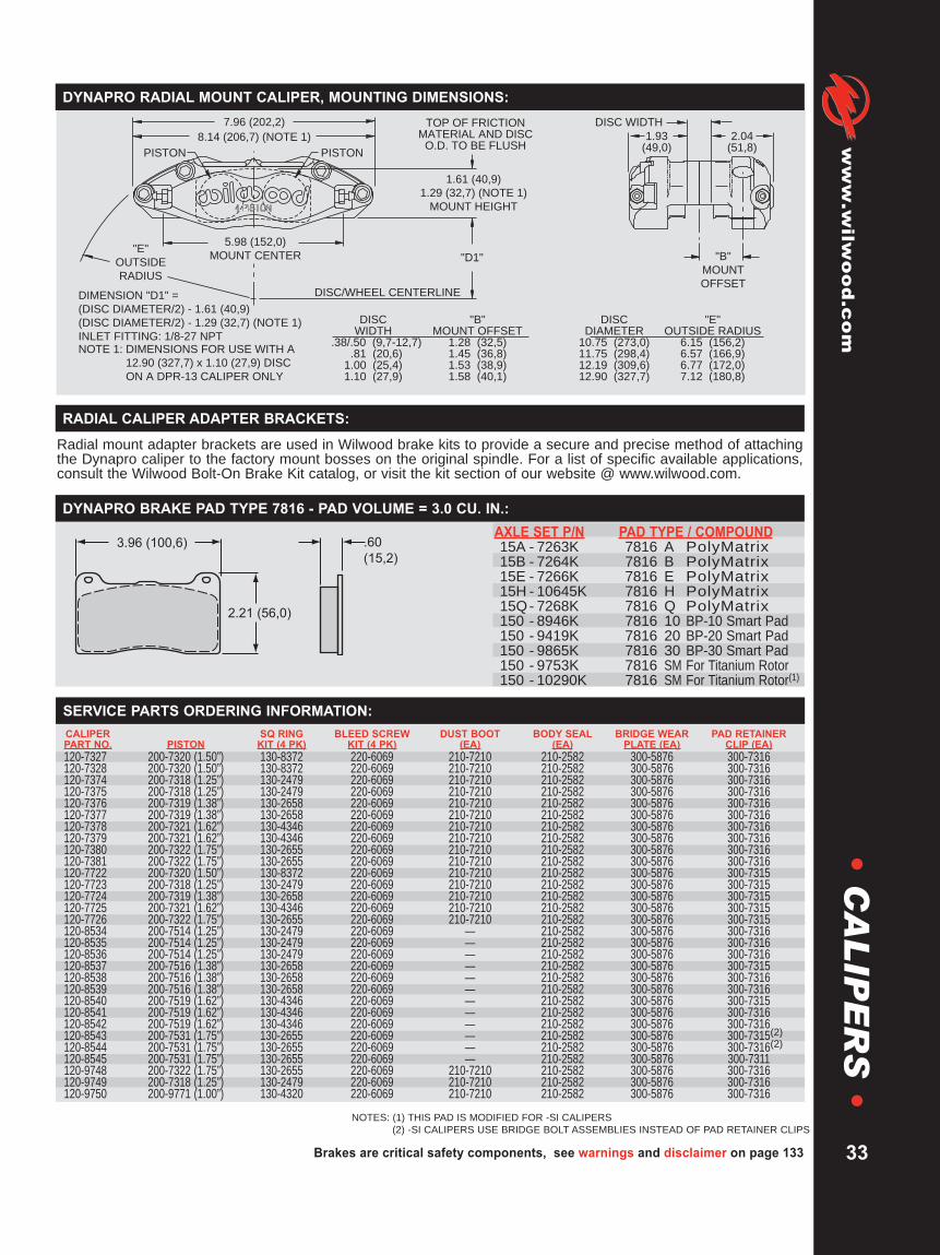
DIMENSION "D1" =
(DISC DIAMETER/2) - 1.61 (40,9)
(DISC DIAMETER/2) - 1.29 (32,7) (NOTE 1)
INLET FITTING: 1/8-27 NPT
DISC/WHEEL CENTERLINE
"B"
MOUNT
OFFSET
"D1"
TOP OF FRICTIONMATERIAL AND DISC
O.D. TO BE FLUSH
DISC WIDTH
1.93(49,0)
2.04(51,8)
5.98 (152,0)
MOUNT CENTER
1.61 (40,9)
1.29 (32,7) (NOTE 1)
MOUNT HEIGHT
8.14 (206,7) (NOTE 1)
7.96 (202,2)
"E"
OUTSIDE
RADIUS
DISCWIDTH
.38/.50 (9,7-12,7).81 (20,6)
1.00 (25,4)1.10 (27,9)
"B"MOUNT OFFSET
1.28 (32,5)1.45 (36,8)1.53 (38,9)1.58 (40,1)
DISCDIAMETER
10.75 (273,0)11.75 (298,4)12.19 (309,6)12.90 (327,7)
"E"OUTSIDE RADIUS
6.15 (156,2)6.57 (166,9)6.77 (172,0)7.12 (180,8)
PISTONPISTON
NOTE 1: DIMENSIONS FOR USE WITH A
12.90 (327,7) x 1.10 (27,9) DISC
ON A DPR-13 CALIPER ONLY
CALIPER SQ RING BLEED SCREW DUST BOOT BODY SEAL BRIDGE WEAR PAD RETAINERPART NO. PISTON KIT (4 PK) KIT (4 PK) (EA) (EA) PLATE (EA) CLIP (EA)120-7327 200-7320 (1.50”) 130-8372 220-6069 210-7210 210-2582 300-5876 300-7316120-7328 200-7320 (1.50”) 130-8372 220-6069 210-7210 210-2582 300-5876 300-7316120-7374 200-7318 (1.25”) 130-2479 220-6069 210-7210 210-2582 300-5876 300-7316120-7375 200-7318 (1.25”) 130-2479 220-6069 210-7210 210-2582 300-5876 300-7316120-7376 200-7319 (1.38”) 130-2658 220-6069 210-7210 210-2582 300-5876 300-7316120-7377 200-7319 (1.38”) 130-2658 220-6069 210-7210 210-2582 300-5876 300-7316120-7378 200-7321 (1.62”) 130-4346 220-6069 210-7210 210-2582 300-5876 300-7316120-7379 200-7321 (1.62”) 130-4346 220-6069 210-7210 210-2582 300-5876 300-7316120-7380 200-7322 (1.75”) 130-2655 220-6069 210-7210 210-2582 300-5876 300-7316120-7381 200-7322 (1.75”) 130-2655 220-6069 210-7210 210-2582 300-5876 300-7316120-7722 200-7320 (1.50”) 130-8372 220-6069 210-7210 210-2582 300-5876 300-7315120-7723 200-7318 (1.25”) 130-2479 220-6069 210-7210 210-2582 300-5876 300-7315120-7724 200-7319 (1.38”) 130-2658 220-6069 210-7210 210-2582 300-5876 300-7315120-7725 200-7321 (1.62”) 130-4346 220-6069 210-7210 210-2582 300-5876 300-7315120-7726 200-7322 (1.75”) 130-2655 220-6069 210-7210 210-2582 300-5876 300-7315120-8534 200-7514 (1.25”) 130-2479 220-6069 — 210-2582 300-5876 300-7316120-8535 200-7514 (1.25”) 130-2479 220-6069 — 210-2582 300-5876 300-7316120-8536 200-7514 (1.25”) 130-2479 220-6069 — 210-2582 300-5876 300-7316120-8537 200-7516 (1.38”) 130-2658 220-6069 — 210-2582 300-5876 300-7315120-8538 200-7516 (1.38”) 130-2658 220-6069 — 210-2582 300-5876 300-7316120-8539 200-7516 (1.38”) 130-2658 220-6069 — 210-2582 300-5876 300-7316120-8540 200-7519 (1.62”) 130-4346 220-6069 — 210-2582 300-5876 300-7315120-8541 200-7519 (1.62”) 130-4346 220-6069 — 210-2582 300-5876 300-7316120-8542 200-7519 (1.62”) 130-4346 220-6069 — 210-2582 300-5876 300-7316120-8543 200-7531 (1.75”) 130-2655 220-6069 — 210-2582 300-5876 300-7315(2)120-8544 200-7531 (1.75”) 130-2655 220-6069 — 210-2582 300-5876 300-7316(2)120-8545 200-7531 (1.75”) 130-2655 220-6069 — 210-2582 300-5876 300-7311120-9748 200-7322 (1.75”) 130-2655 220-6069 210-7210 210-2582 300-5876 300-7316120-9749 200-7318 (1.25”) 130-2479 220-6069 210-7210 210-2582 300-5876 300-7316120-9750 200-9771 (1.00”) 130-4320 220-6069 210-7210 210-2582 300-5876 300-7316
Brakes are critical safety components, see warnings and disclaimer on page 133
www.wilw
ood.com
33
•C
AL
IPE
RS
•DYNAPRO RADIAL MOUNT CALIPER, MOUNTING DIMENSIONS:
SERVICE PARTS ORDERING INFORMATION:
Radial mount adapter brackets are used in Wilwood brake kits to provide a secure and precise method of attachingthe Dynapro caliper to the factory mount bosses on the original spindle. For a list of specific available applications,consult the Wilwood Bolt-On Brake Kit catalog, or visit the kit section of our website @ www.wilwood.com.
RADIAL CALIPER ADAPTER BRACKETS:
2.21 (56,0)
.60
(15,2)
3.96 (100,6)AXLE SET P/N PAD TYPE / COMPOUND15A - 7263K 7816 A PolyMatrix15B - 7264K 7816 B PolyMatrix15E - 7266K 7816 E PolyMatrix15H - 10645K 7816 H PolyMatrix15Q- 7268K 7816 Q PolyMatrix150 - 8946K 7816 10 BP-10 Smart Pad150 - 9419K 7816 20 BP-20 Smart Pad150 - 9865K 7816 30 BP-30 Smart Pad150 - 9753K 7816 SM For Titanium Rotor150 - 10290K 7816 SM For Titanium Rotor(1)
DYNAPRO BRAKE PAD TYPE 7816 - PAD VOLUME = 3.0 CU. IN.:
NOTES: (1) THIS PAD IS MODIFIED FOR -SI CALIPERS(2) -SI CALIPERS USE BRIDGE BOLT ASSEMBLIES INSTEAD OF PAD RETAINER CLIPS

WARNING: The user or installer of any product from this catalog must determine its suitability for their intended purpose or application
www.wilwood.com
34
•C
AL
IPE
RS
•BILLET DYNAPRO 6 LUG MOUNT CALIPER
CALIPER ORDERING INFORMATION:(1)
BORE SIZE DISC WIDTH RH LH1.62 / 1.38 / 1.38” 1.10” 27,9 mm 120-10120 (2,3) 120-10121 (2,3)
41,1 / 35,1 / 35,1 mm1.62 / 1.38 / 1.38” .81” 20,1 mm 120-10122 (2,3) 120-10123 (2,3)
41,1 / 35,1 / 35,1 mm1.62 / 1.38 / 1.38” .38” 9,6 mm 120-10124 (2,3) 120-10125 (2,3)
41,1 / 35,1 / 35,1 mm1.62 / 1.12 / 1.12” 1.10” 27,9 mm 120-10126 (2,3) 120-10127 (2,3)
41,1 / 28,4 / 28,4 mm1.62 / 1.12 / 1.12” .81” 20,1 mm 120-10128 (4) 2 120-10129 (2,3,4)
41,1 / 28,4 / 28,4 mm1.62 / 1.12 / 1.12” .38” 9,6 mm 120-10130 (2,3) 120-10131 (2,3)
41,1 / 28,4 / 28,4 mm1.38 / 1.00 / 1.00” 1.10” 27,9 mm 120-10132 (2,3) 120-10133 (2,3)
35,1 / 25,4 / 25,4 mm1.38 / 1.00 / 1.00” .81” 20.1 mm 120-10134 (2,3) 120-10135 (2,3,4)
35,1 / 25,4 / 25,4 mm1.38 / 1.00 / 1.00” .38” 9,6 mm 120-10136 (2,3) 120-10137 (2,3)
35,1 / 25,4 / 25,4 mm
Caliper Highlights:The DP6 marks a noteworthy step in the evolution ofthe DynaPro caliper series. DP6 calipers offer theperformance advantages of a larger pad and a sixpiston differential bore configuration, with completebolt-on interchange ability to the four piston 5.25" lugmount DynaPro models, and the long standingDynalite caliper series.
As with the previous DynaPro models, the strengthof the DP6 is a combination of process and design. Premiumgrade alloy billets are stress-flow forged resulting in a highly efficient,high strength body. Stress flow forging re-aligns the internal grain structure ofthe metal within the contour of the caliper body. This process is proven to providesuperior strength over any other process derived from castings or straight billetblock machining. FEA assisted solid modeling design technology was employedto find the optimum balance between lightweight with superior strength againstdeflection and body separation under high load.
In addition to the sturdy, yet stylish body, the DP6 incorporates race proven technology and the latest Wilwoodperformance enhancements. Pad clamping force is generated by six heavy wall stainless pistons configured in a leadingto trailing edge differential bore pattern. The heavy wall pistons have been re-engineered to fully resist backsidedeflection at high pressures while maintaining balanced pad loading for even wear over the length of the pad. Stainlesssteel resists corrosion while inhibiting direct heat transfer from the pads to caliper body, seals, and fluid. Two choices foroverall piston volume provide options to match caliper size with master cylinder output and bias requirements.
The DP6 uses the upgraded type 6712 pad that provide the larger overall volume size from the previous Dynalite andDynaPro four-piston models. The pads are retaining with exclusive Wilwood Quick-E clips for simplified pad service andmaintenance without caliper removal. Stainless steel SRS bridge plates are used to dampen engagement harmonics,eliminate pad rattle, and protect the caliper bridges from gouging by the pad edges. Four corner bleeds and internal fluidpassages accommodate front or rear mounting and simplified gas evacuation regardless of mounting position.
Standard DP6 calipers feature a high gloss black finish. Bright polished, high gloss red, and other custom Wilwood colorscan be ordered to add personalized style for custom applications.
Red
NOTES: (1) REFERENCE FRONT OF MANUAL FOR GENERAL ORDERING INFORMATION(2) AVAILABLE RED, ADD “RD” TO END OF PART NUMBER WHEN ORDERING(3) AVAILABLE SILVER, ADD “S’ TO END OF PART NUMBER WHEN ORDERING(4) AVAILABLE POLISHED, ADD ‘’P’ TO END OF PART NUMBER WHEN ORDERING
PolishedBlack
Silver

Brakes are critical safety components, see warnings and disclaimer on page 133
www.wilw
ood.com
35
•C
AL
IPE
RS
•
CALIPER SQ RING BLEED SCREW BODY BRIDGE WEAR PAD RETAINERPART NO. PISTON KIT (6 PK) KIT (4 PK) SEAL (EA) PLATE (EA) CLIP PIN (EA)
120-10120 200-7520 (1.62”) 130-10535 220-0627 210-2582 300-9707 300-7316200-7518 (1.38”)
120-10121 200-7520 (1.62”) 130-10535 220-0627 210-2582 300-9707 300-7316200-7518 (1.38”)
120-10122 200-7520 (1.62”) 130-10535 220-0627 210-2582 300-9707 300-7316200-7518 (1.38”)
120-10123 200-7520 (1.62”) 130-10535 220-0627 210-2582 300-9707 300-7316200-7518 (1.38”)
120-10124 200-7520 (1.62”) 130-10535 220-0627 210-2582 300-9707 300-7315200-7518 (1.38”)
120-10125 200-7520 (1.62”) 130-10535 220-0627 210-2582 300-9707 300-7315200-7518 (1.38”)
120-10126 200-7520 (1.62”) 130-5972 220-0627 210-2582 300-9707 300-7316200-8439 (1.12”)
120-10127 200-7520 (1.62”) 130-5972 220-0627 210-2582 300-9707 300-7316200-8439 (1.12”)
120-10128 200-7520 (1.62”) 130-5972 220-0627 210-2582 300-9707 300-7316200-8439 (1.12”)
120-10129 200-7520 (1.62”) 130-5972 220-0627 210-2582 300-9707 300-7316200-8439 (1.12”)
120-10130 200-7520 (1.62”) 130-5972 220-0627 210-2582 300-9707 300-7315200-8439 (1.12”)
120-10131 200-7520 (1.62”) 130-5972 220-0627 210-2582 300-9707 300-7315200-8439 (1.12”)
120-10132 200-7518 (1.38”) 130-10169 220-0627 210-2582 300-9707 300-7316200-6979 (1.00”)
120-10133 200-7518 (1.38”) 130-10169 220-0627 210-2582 300-9707 300-7316200-6979 (1.00”)
120-10134 200-7518 (1.38”) 130-10169 220-0627 210-2582 300-9707 300-7316200-6979 (1.00”)
120-10135 200-7518 (1.38”) 130-10169 220-0627 210-2582 300-9707 300-7316200-6979 (1.00”)
120-10136 200-7518 (1.38”) 130-10169 220-0627 210-2582 300-9707 300-7315200-6979 (1.00”)
120-10137 200-7518 (1.38”) 130-10169 220-0627 210-2582 300-9707 300-7315200-6979 (1.00”)
DYNAPRO 6 LUG MOUNT CALIPER SERVICE PARTS ORDERING INFORMATION:
DIMENSION "D1" = (DISC DIAMETER/2) - 2.02 (51,3)
"A"
BOLT CIRCLE RADIUS
3.96 (100,7)
4.16 (105,5)
4.25 (108,0)
4.35 (110.5)
4.53 (115,0)
4.66 (118,3)
4.84 (122,9)
5.14 (130,6)
DISC
DIAMETER
10.00 (254,0)
10.50 (266,7)
10.75 (273,1)
11.00 (279,4)
11.44 (290,5)
11.75 (298,5)
12.19 (309,6)
12.90 (327,7)
"E"
OUTSIDE RADIUS
6.18 (156,9)
6.34 (161,1)
6.43 (163,2)
6.51 (165,4)
6.67 (169,3)
6.78 (172,1)
6.94 (176,1)
7.20 (182,9)
DISC
WIDTH
1.10 (27,9)
.81 (20,6)
.38 (9,7)
"B"
MOUNT OFFSET
1.13 (28,7)
.98 (25,0)
.76 (19,3)NOTE: RIGHT HAND CALIPER SHOWN.
INLET FITTING: 1/8-27 NPT
2.02 (51,3)
MOUNT HEIGHT
"D1"
DISC WIDTH
"B" MOUNT OFFSET.39 (9,9)
MOUNT HOLE5.25 (133,4)
MOUNT CENTER
"E"
OUTSIDE
RADIUS
"A"
BOLT CIRCLE
RADIUS DISC/WHEEL CENTERLINE
TOP OF FRICTION
MATERIAL AND DISC]
O.D. TO BE FLUSH1.64 (41,5)1.64 (41,5)DISC ROTATION
9.64 (244,8)
SMALL PISTONLARGE PISTON
DYNAPRO 6 LUG MOUNT CALIPER, MOUNTING DIMENSIONS:
2.36 (59,9)
.49(12,4)
4.86 (123,4) AXLE SET P/N PAD TYPE / COMPOUND15A - 10724K 6712 A PolyMatrix15B - 10725K 6712 B PolyMatrix15H - 10726K 6712 H PolyMatrix150 - 10006K 6712 10 BP-10 Smart Pad150 - 10007K 6712 20 BP-20 Smart Pad
DYNAPRO 6 BRAKE PAD TYPE 6712 - PAD VOLUME = 2.4 CU. IN.:
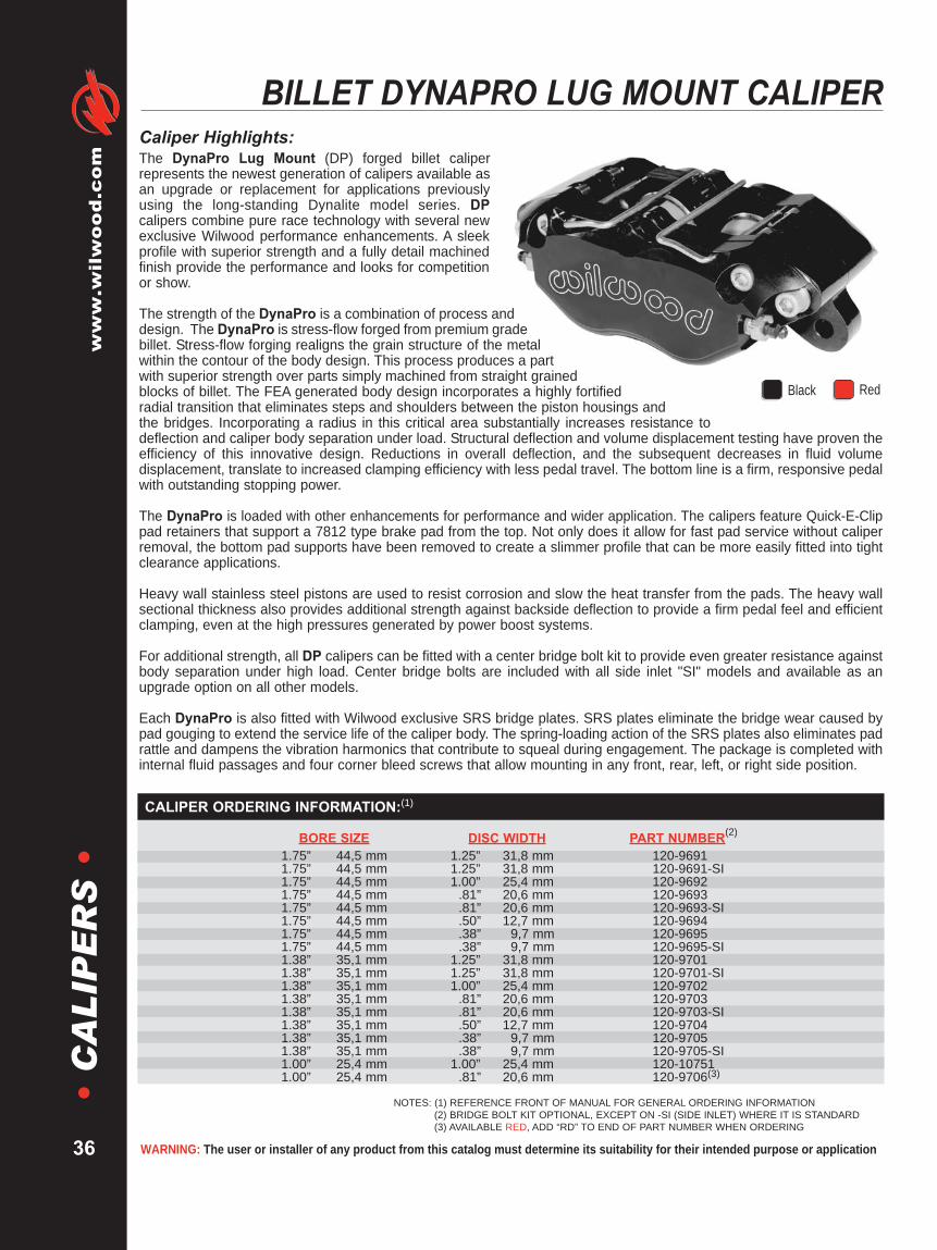
WARNING: The user or installer of any product from this catalog must determine its suitability for their intended purpose or application
www.wilwood.com
36
•C
AL
IPE
RS
•BILLET DYNAPRO LUG MOUNT CALIPER
Caliper Highlights:The DynaPro Lug Mount (DP) forged billet caliperrepresents the newest generation of calipers available asan upgrade or replacement for applications previouslyusing the long-standing Dynalite model series. DPcalipers combine pure race technology with several newexclusive Wilwood performance enhancements. A sleekprofile with superior strength and a fully detail machinedfinish provide the performance and looks for competitionor show.
The strength of the DynaPro is a combination of process anddesign. The DynaPro is stress-flow forged from premium gradebillet. Stress-flow forging realigns the grain structure of the metalwithin the contour of the body design. This process produces a partwith superior strength over parts simply machined from straight grainedblocks of billet. The FEA generated body design incorporates a highly fortifiedradial transition that eliminates steps and shoulders between the piston housings andthe bridges. Incorporating a radius in this critical area substantially increases resistance todeflection and caliper body separation under load. Structural deflection and volume displacement testing have proven theefficiency of this innovative design. Reductions in overall deflection, and the subsequent decreases in fluid volumedisplacement, translate to increased clamping efficiency with less pedal travel. The bottom line is a firm, responsive pedalwith outstanding stopping power.
The DynaPro is loaded with other enhancements for performance and wider application. The calipers feature Quick-E-Clippad retainers that support a 7812 type brake pad from the top. Not only does it allow for fast pad service without caliperremoval, the bottom pad supports have been removed to create a slimmer profile that can be more easily fitted into tightclearance applications.
Heavy wall stainless steel pistons are used to resist corrosion and slow the heat transfer from the pads. The heavy wallsectional thickness also provides additional strength against backside deflection to provide a firm pedal feel and efficientclamping, even at the high pressures generated by power boost systems.
For additional strength, all DP calipers can be fitted with a center bridge bolt kit to provide even greater resistance againstbody separation under high load. Center bridge bolts are included with all side inlet "SI" models and available as anupgrade option on all other models.
Each DynaPro is also fitted with Wilwood exclusive SRS bridge plates. SRS plates eliminate the bridge wear caused bypad gouging to extend the service life of the caliper body. The spring-loading action of the SRS plates also eliminates padrattle and dampens the vibration harmonics that contribute to squeal during engagement. The package is completed withinternal fluid passages and four corner bleed screws that allow mounting in any front, rear, left, or right side position.
NOTES: (1) REFERENCE FRONT OF MANUAL FOR GENERAL ORDERING INFORMATION(2) BRIDGE BOLT KIT OPTIONAL, EXCEPT ON -SI (SIDE INLET) WHERE IT IS STANDARD(3) AVAILABLE RED, ADD “RD” TO END OF PART NUMBER WHEN ORDERING
BORE SIZE DISC WIDTH PART NUMBER(2)
1.75” 44,5 mm 1.25” 31,8 mm 120-96911.75” 44,5 mm 1.25” 31,8 mm 120-9691-SI1.75” 44,5 mm 1.00” 25,4 mm 120-96921.75” 44,5 mm .81” 20,6 mm 120-96931.75” 44,5 mm .81” 20,6 mm 120-9693-SI1.75” 44,5 mm .50” 12,7 mm 120-96941.75” 44,5 mm .38” 9,7 mm 120-96951.75” 44,5 mm .38” 9,7 mm 120-9695-SI1.38” 35,1 mm 1.25” 31,8 mm 120-97011.38” 35,1 mm 1.25” 31,8 mm 120-9701-SI1.38” 35,1 mm 1.00” 25,4 mm 120-97021.38” 35,1 mm .81” 20,6 mm 120-97031.38” 35,1 mm .81” 20,6 mm 120-9703-SI1.38” 35,1 mm .50” 12,7 mm 120-97041.38” 35,1 mm .38” 9,7 mm 120-97051.38” 35,1 mm .38” 9,7 mm 120-9705-SI1.00” 25,4 mm 1.00” 25,4 mm 120-107511.00” 25,4 mm .81” 20,6 mm 120-9706(3)
CALIPER ORDERING INFORMATION:(1)
Black Red

DIMENSION "D1" =(DISC DIAMETER/2) - 2.07 (52,6)
INLET FITTING: 1/8-27 NPT
DISC/WHEEL CENTERLINE
"B"MOUNT OFFSET"D1"
2.07 (52,6)MOUNT HEIGHT.39 (9,9)
MOUNT HOLE
TOP OF FRICTION MATERIALAND DISC O.D. TO BE FLUSH
DISC WIDTH
1.67(42,4)
1.67(42,4)
5.25 (133,4)MOUNT CENTER
7.01 (178,1)
"E"OUTSIDERADIUS
"A"BOLT CIRCLE RADIUS
3.93 (99,8)4.12 (104,6)4.22 (107,2)4.32 (109,7)4.50 (114,3)4.63 (117,6)4.81 (122,2)
DISCDIAMETER
10.00 (254,0)10.50 (266,7)10.75 (273,1)11.00 (279,4)11.44 (290,6)11.75 (298,5)12.19 (309,6)
"E"OUTSIDE RADIUS
6.02 (152,9)6.23 (158,2)6.34 (161,0)6.44 (163,6)6.63 (168,4)6.76 (171,7)6.97 (177,0)
DISC WIDTH.38 (9,7).50 (12,7).81 (20,6)
1.00 (25,4)1.25 (31,8)
"B" MOUNT OFFSET.76 (19,3).82 (20,8).98 (24,9)
1.08 (27,4)1.20 (30,5)
"A"BOLT CIRCLE RADIUS
PISTON PISTON
Brakes are critical safety components, see warnings and disclaimer on page 133
www.wilw
ood.com
37
•C
AL
IPE
RS
•DYNAPRO LUG MOUNT CALIPER, MOUNTING DIMENSIONS:
2.21 (56,0)
.49
(12,4)
3.96 (100,6) AXLE SET P/N PAD TYPE / COMPOUND15A - 9835K 7812 A PolyMatrix15B - 9836K 7812 B PolyMatrix15E - 9837K 7812 E PolyMatrix15H - 10644K 7812 H PolyMatrix15Q- 10385K 7812 Q PolyMatrix150 - 9136K 7812 10 BP-10 Smart Pad150 - 9418K 7812 20 BP-20 Smart Pad150 - 10020K 7812 CMFor Titanium Rotor
DYNAPRO BRAKE PAD TYPE 7812 - PAD VOLUME = 2.1 CU. IN.:
CALIPER SQ RING BLEED SCREW BODY SEAL BRIDGE WEAR PAD RETAINER BRIDGE BOLTPART NO. PISTON (4 PK) KIT (4 PK) (EA) PLATE (EA) CLIP PIN (EA) KIT (EA)120-9691 200-7528 (1.75”) 130-2655 220-0627 210-2582 300-5875 300-9638 230-10119120-9692 200-7528 (1.75”) 130-2655 220-0627 210-2582 300-5875 300-9637 —120-9693 200-7528 (1.75”) 130-2655 220-0627 210-2582 300-5875 300-9636 230-10118120-9694 200-7528 (1.75”) 130-2655 220-0627 210-2582 300-5875 300-9635 —120-9695 200-7528 (1.75”) 130-2655 220-0627 210-2582 300-5875 300-9634 230-10117120-9701 200-7518 (1.38”) 130-2658 220-0627 210-2582 300-5875 300-9638 230-10119120-9702 200-7518 (1.38”) 130-2658 220-0627 210-2582 300-5875 300-9637 —120-9703 200-7518 (1.38”) 130-2658 220-0627 210-2582 300-5875 300-9636 230-10118120-9704 200-7518 (1.38”) 130-2658 220-0627 210-2582 300-5875 300-9635 —120-9705 200-7518 (1.38”) 130-2658 220-0627 210-2582 300-5875 300-9634 230-10117120-9706 200-6979 (1.00”) 130-4320 220-0627 210-2582 300-5875 300-9636 230-10118
SERVICE PARTS ORDERING INFORMATION:
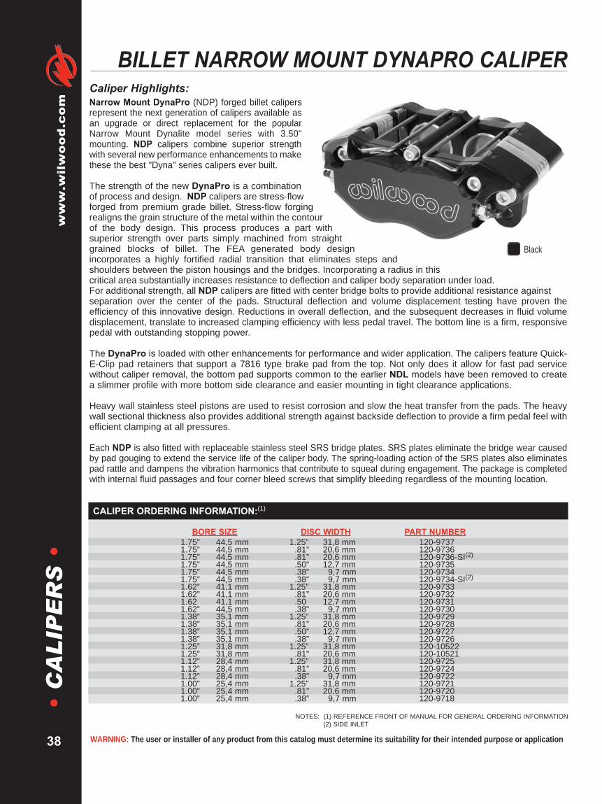
WARNING: The user or installer of any product from this catalog must determine its suitability for their intended purpose or application
www.wilwood.com
38
•C
AL
IPE
RS
•BILLET NARROW MOUNT DYNAPRO CALIPER
Caliper Highlights:Narrow Mount DynaPro (NDP) forged billet calipersrepresent the next generation of calipers available asan upgrade or direct replacement for the popularNarrow Mount Dynalite model series with 3.50"mounting. NDP calipers combine superior strengthwith several new performance enhancements to makethese the best "Dyna" series calipers ever built.
The strength of the new DynaPro is a combinationof process and design. NDP calipers are stress-flowforged from premium grade billet. Stress-flow forgingrealigns the grain structure of the metal within the contourof the body design. This process produces a part withsuperior strength over parts simply machined from straightgrained blocks of billet. The FEA generated body designincorporates a highly fortified radial transition that eliminates steps andshoulders between the piston housings and the bridges. Incorporating a radius in thiscritical area substantially increases resistance to deflection and caliper body separation under load.For additional strength, all NDP calipers are fitted with center bridge bolts to provide additional resistance againstseparation over the center of the pads. Structural deflection and volume displacement testing have proven theefficiency of this innovative design. Reductions in overall deflection, and the subsequent decreases in fluid volumedisplacement, translate to increased clamping efficiency with less pedal travel. The bottom line is a firm, responsivepedal with outstanding stopping power.
The DynaPro is loaded with other enhancements for performance and wider application. The calipers feature Quick-E-Clip pad retainers that support a 7816 type brake pad from the top. Not only does it allow for fast pad servicewithout caliper removal, the bottom pad supports common to the earlier NDL models have been removed to createa slimmer profile with more bottom side clearance and easier mounting in tight clearance applications.
Heavy wall stainless steel pistons are used to resist corrosion and slow the heat transfer from the pads. The heavywall sectional thickness also provides additional strength against backside deflection to provide a firm pedal feel withefficient clamping at all pressures.
Each NDP is also fitted with replaceable stainless steel SRS bridge plates. SRS plates eliminate the bridge wear causedby pad gouging to extend the service life of the caliper body. The spring-loading action of the SRS plates also eliminatespad rattle and dampens the vibration harmonics that contribute to squeal during engagement. The package is completedwith internal fluid passages and four corner bleed screws that simplify bleeding regardless of the mounting location.
NOTES: (1) REFERENCE FRONT OF MANUAL FOR GENERAL ORDERING INFORMATION(2) SIDE INLET
Black
BORE SIZE DISC WIDTH PART NUMBER1.75” 44,5 mm 1.25” 31,8 mm 120-97371.75” 44,5 mm .81” 20,6 mm 120-97361.75” 44,5 mm .81” 20,6 mm 120-9736-SI(2)1.75” 44,5 mm .50” 12,7 mm 120-97351.75” 44,5 mm .38” 9,7 mm 120-97341.75” 44,5 mm .38” 9,7 mm 120-9734-SI(2)1.62” 41,1 mm 1.25” 31,8 mm 120-97331.62” 41,1 mm .81” 20,6 mm 120-97321.62 41,1 mm .50 12,7 mm 120-97311.62” 44,5 mm .38” 9,7 mm 120-97301.38” 35,1 mm 1.25” 31,8 mm 120-97291.38” 35,1 mm .81” 20,6 mm 120-97281.38” 35,1 mm .50” 12,7 mm 120-97271.38” 35,1 mm .38” 9,7 mm 120-97261.25” 31,8 mm 1.25” 31,8 mm 120-105221.25” 31,8 mm .81” 20,6 mm 120-105211.12” 28,4 mm 1.25” 31,8 mm 120-97251.12” 28,4 mm .81” 20,6 mm 120-97241.12” 28,4 mm .38” 9,7 mm 120-97221.00” 25,4 mm 1.25” 31,8 mm 120-97211.00” 25,4 mm .81” 20,6 mm 120-97201.00” 25,4 mm .38” 9,7 mm 120-9718
CALIPER ORDERING INFORMATION:(1)
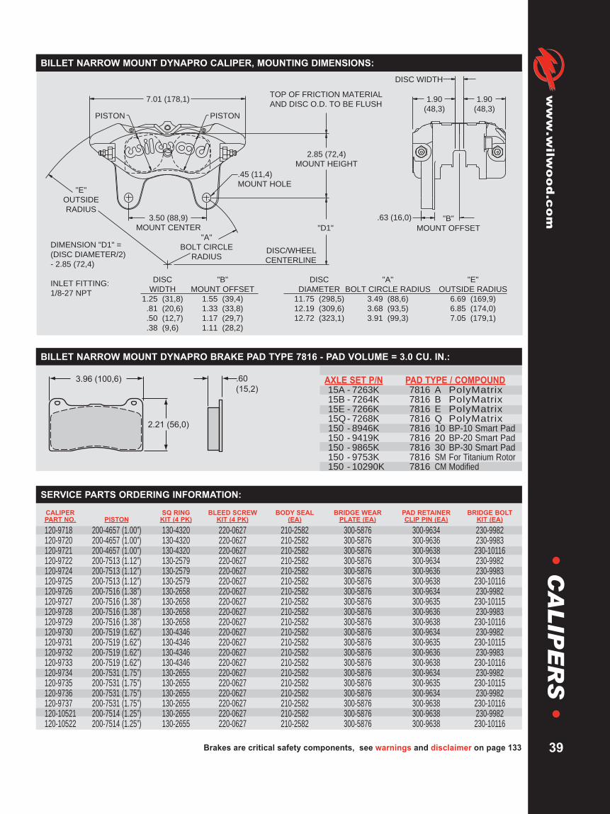
"D1"
.63 (16,0)
7.01 (178,1)
PISTONPISTON
1.90
(48,3)
1.90
(48,3)
2.85 (72,4)
MOUNT HEIGHT
DISC WIDTH
"B"
MOUNT OFFSET
.45 (11,4)
MOUNT HOLE
3.50 (88,9)
MOUNT CENTER
"E"
OUTSIDE
RADIUS
DISC/WHEEL
CENTERLINE
"A"
BOLT CIRCLE
RADIUS
DIMENSION "D1" =
(DISC DIAMETER/2)
- 2.85 (72,4)
INLET FITTING:
1/8-27 NPT
TOP OF FRICTION MATERIAL
AND DISC O.D. TO BE FLUSH
DISC
DIAMETER
11.75 (298,5)
12.19 (309,6)
12.72 (323,1)
"E"
OUTSIDE RADIUS
6.69 (169,9)
6.85 (174,0)
7.05 (179,1)
DISC
WIDTH
1.25 (31,8)
.81 (20,6)
.50 (12,7)
.38 (9,6)
"B"
MOUNT OFFSET
1.55 (39,4)
1.33 (33,8)
1.17 (29,7)
1.11 (28,2)
"A"
BOLT CIRCLE RADIUS
3.49 (88,6)
3.68 (93,5)
3.91 (99,3)
Brakes are critical safety components, see warnings and disclaimer on page 133
www.wilw
ood.com
39
•C
AL
IPE
RS
•BILLET NARROW MOUNT DYNAPRO CALIPER, MOUNTING DIMENSIONS:
2.21 (56,0)
.60
(15,2)
3.96 (100,6) AXLE SET P/N PAD TYPE / COMPOUND15A - 7263K 7816 A PolyMatrix15B - 7264K 7816 B PolyMatrix15E - 7266K 7816 E PolyMatrix15Q- 7268K 7816 Q PolyMatrix150 - 8946K 7816 10 BP-10 Smart Pad150 - 9419K 7816 20 BP-20 Smart Pad150 - 9865K 7816 30 BP-30 Smart Pad150 - 9753K 7816 SM For Titanium Rotor150 - 10290K 7816 CM Modified
BILLET NARROW MOUNT DYNAPRO BRAKE PAD TYPE 7816 - PAD VOLUME = 3.0 CU. IN.:
CALIPER SQ RING BLEED SCREW BODY SEAL BRIDGE WEAR PAD RETAINER BRIDGE BOLTPART NO. PISTON KIT (4 PK) KIT (4 PK) (EA) PLATE (EA) CLIP PIN (EA) KIT (EA)
120-9718 200-4657 (1.00”) 130-4320 220-0627 210-2582 300-5876 300-9634 230-9982120-9720 200-4657 (1.00”) 130-4320 220-0627 210-2582 300-5876 300-9636 230-9983120-9721 200-4657 (1.00”) 130-4320 220-0627 210-2582 300-5876 300-9638 230-10116120-9722 200-7513 (1.12”) 130-2579 220-0627 210-2582 300-5876 300-9634 230-9982120-9724 200-7513 (1.12”) 130-2579 220-0627 210-2582 300-5876 300-9636 230-9983120-9725 200-7513 (1.12”) 130-2579 220-0627 210-2582 300-5876 300-9638 230-10116120-9726 200-7516 (1.38”) 130-2658 220-0627 210-2582 300-5876 300-9634 230-9982120-9727 200-7516 (1.38”) 130-2658 220-0627 210-2582 300-5876 300-9635 230-10115120-9728 200-7516 (1.38”) 130-2658 220-0627 210-2582 300-5876 300-9636 230-9983120-9729 200-7516 (1.38”) 130-2658 220-0627 210-2582 300-5876 300-9638 230-10116120-9730 200-7519 (1.62”) 130-4346 220-0627 210-2582 300-5876 300-9634 230-9982120-9731 200-7519 (1.62”) 130-4346 220-0627 210-2582 300-5876 300-9635 230-10115120-9732 200-7519 (1.62”) 130-4346 220-0627 210-2582 300-5876 300-9636 230-9983120-9733 200-7519 (1.62”) 130-4346 220-0627 210-2582 300-5876 300-9638 230-10116120-9734 200-7531 (1.75”) 130-2655 220-0627 210-2582 300-5876 300-9634 230-9982120-9735 200-7531 (1.75”) 130-2655 220-0627 210-2582 300-5876 300-9635 230-10115120-9736 200-7531 (1.75”) 130-2655 220-0627 210-2582 300-5876 300-9634 230-9982120-9737 200-7531 (1.75”) 130-2655 220-0627 210-2582 300-5876 300-9638 230-10116120-10521 200-7514 (1.25”) 130-2655 220-0627 210-2582 300-5876 300-9638 230-9982120-10522 200-7514 (1.25”) 130-2655 220-0627 210-2582 300-5876 300-9638 230-10116
SERVICE PARTS ORDERING INFORMATION:

WARNING: The user or installer of any product from this catalog must determine its suitability for their intended purpose or application
www.wilwood.com
40
•C
AL
IPE
RS
•NARROW MOUNT DYNALITE CALIPER
NOTES: (1) REFERENCE FRONT OF MANUAL FOR GENERAL ORDERING INFORMATION
Caliper Highlights:Wilwood's Narrow Mount Dynalite (NDL) calipersare ideal for and widely used in many competitionapplications including late models, modifieds,sprints, off road and road racing. Computergenerated design and stress analysis technology,modern permanent mold manufacturing techniques,and time proven performance features have beencombined in the newest version of this popularcaliper configuration.
NDL calipers are manufactured using a high strength yetlightweight aircraft alloy. Caliper weights starting at 3.28 pounds. TheNDL body features an FEA generated radial transition design that eliminates stepsand shoulders in the area between the piston housing body and the caliper bridges. Incorporatinga radius in this transition area substantially increases resistance to deflection and caliper separation under severeload. Structural deflection and volume displacement tests have proven the NDL to outperform all existing styles ofthis popular caliper size. Lower deflection and the resulting decrease in fluid volume displacement translate toincreased clamping efficiency with less pedal travel. The bottom line is better stopping power with a solid pedal.
The superior strength of the NDL is combined with proven performance features from other Wilwood designs. EveryNDL caliper is equipped with Wilwood's SRS stainless steel bridge plates. The SRS plates eliminate the bridge wearcaused by pad gouging and extend the service life of the caliper body. The spring-loading action of the SRS platesalso eliminates pad rattle and dampens the vibration harmonics that contribute to squeal under braking.
Internal fluid passages eliminate the need for external tubes. Four corner bleed screws assure simple and effectiveair evacuation from the system and allow one caliper to be mounted in any front, rear, right or left position. Otherstandard Wilwood features include stainless steel pistons to eliminate corrosion and retard heat transfer from thepads, high temperature seals, and an attractive high luster black anodized finish.
NDL calipers are a direct replacement for all previous Wilwood NDL’s and similar competitive brands with 3.50"centered mounting tabs. A total of five bolts provide superior bridge strength and positive retention of the top loaded7216 type brake pads. The full range of Wilwood pad compounds is available to match the brake response and heatrange requirements of any competition application.
BORE SIZE DISC WIDTH PART NUMBER1.75” 44,5 mm 1.25” 31,8 mm 120-65001.75” 44,5 mm .81” 20,6 mm 120-65011.75” 44,5 mm .81” 20,6 mm 120-6501-SI1.75” 44,5 mm .50” 12,7 mm 120-65021.75” 44,5 mm .38” 9,7 mm 120-65031.75” 44,5 mm .38” 9,7 mm 120-6503-SI1.62” 41,1 mm 1.25” 31,8 mm 120-65041.62” 41,1 mm .81” 20,6 mm 120-65051.62” 41,1 mm .50” 12,7 mm 120-65061.62” 41,1 mm .38” 9,7 mm 120-65071.38” 35,1 mm 1.25” 31,8 mm 120-65081.38” 35,1 mm .81” 20,6 mm 120-65091.38” 35,1 mm .50” 12,7 mm 120-65101.38” 35,1 mm .38” 9,7 mm 120-6511
CALIPER ORDERING INFORMATION:(1)
Black

2.30 (58,4)
.63
(16,0)
3.96 (100,6)
"D1" .63
7.01 (178,1)
PISTONPISTON
1.93
(49,0)
1.93
(49,0)
2.85 (72,4)
MOUNT HEIGHT
DISC WIDTH
"B"
MOUNT OFFSET
.45 (11,4)
MOUNT HOLE
3.50 (88,9)
MOUNT CENTER
"E"
OUTSIDE
RADIUS
DISC/WHEEL
CENTERLINE
"A"
BOLT CIRCLE
RADIUSDIMENSION "D1" =
(DISC DIAMETER/2) - 2.85 (72,4)
INLET FITTING: 1/8-27 NPT
TOP OF FRICTION MATERIAL
AND DISC O.D. TO BE FLUSH
DISC
DIAMETER
11.75 (298,5)
12.19 (309,6)
"E"
OUTSIDE RADIUS
6.74 (171,2)
6.94 (176,3)
DISC
WIDTH
1.25 (31,8)
.81 (20,6)
.50 (12,7)
.38 (9,6)
"B"
MOUNT OFFSET
1.55 (39,4)
1.33 (33,8)
1.17 (29,7)
1.11 (28,2)
"A"
BOLT CIRCLE RADIUS
3.49 (88,6)
3.69 (93,7)
Brakes are critical safety components, see warnings and disclaimer on page 133
www.wilw
ood.com
41
•C
AL
IPE
RS
•NDL CALIPER, MOUNTING DIMENSIONS:
AXLE SET P/N(1) PAD TYPE / COMPOUND15A - 5769K 7216 A PolyMatrix15B - 4410K 7216 B PolyMatrix15C - 4959K 7216 C PolyMatrix15E - 6099K 7216 E PolyMatrix15H - 8290K 7216 H PolyMatrix15Q- 6826K 7216 Q PolyMatrix150 - 8858K 7216 10 BP-10 Smart Pad150 - 9419K 7216 20 BP-20 Smart Pad150 - 7504K 7216 SM For Titanium Rotor
NDL BRAKE PAD TYPE 7216 - PAD VOLUME = 3.0 CU. IN.:
CALIPER SQ RING BLEED SCREW BODY SEAL BRIDGE WEARPART NO. PISTON KIT (4 PK) KIT (4 PK) (EA) PLATE (EA)120-6500 200-7531 (1.75”) 130-2655 220-0627 210-2582 300-5876120-6501 200-7531 (1.75”) 130-2655 220-0627 210-2582 300-5876120-6502 200-7531 (1.75”) 130-2655 220-0627 210-2582 300-5876120-6503 200-7531 (1.75”) 130-2655 220-0627 210-2582 300-5876120-6504 200-7519 (1.62”) 130-4346 220-0627 210-2582 300-5876120-6505 200-7519 (1.62”) 130-4346 220-0627 210-2582 300-5876120-6506 200-7519 (1.62”) 130-4346 220-0627 210-2582 300-5876120-6507 200-7519 (1.62”) 130-4346 220-0627 210-2582 300-5876120-6508 200-7516 (1.38”) 130-2658 220-0627 210-2582 300-5876120-6509 200-7516 (1.38”) 130-2658 220-0627 210-2582 300-5876120-6510 200-7516 (1.38”) 130-2658 220-0627 210-2582 300-5876120-6511 200-7516 (1.38”) 130-2658 220-0627 210-2582 300-5876
SERVICE PARTS ORDERING INFORMATION:
NOTES: (1) SUBJECT TO AVAILABLE INVENTORY, PAD TYPE 7216 MAY BE REPLACED WITH PAD TYPE 7816. SEE PAGE 63 FOR ORDERING INFORMATION.
Can also use pad type 7816 for this application. See pad section page 63

WARNING: The user or installer of any product from this catalog must determine its suitability for their intended purpose or application
www.wilwood.com
42
•C
AL
IPE
RS
•FORGED BILLET DYNALITE CALIPER
Caliper Highlights:The Forged Billet Dynalite has wide spread application over manyforms over motorsports. It serves as the base model in the majorityof Wilwood's Bolt-On Disc Brake Kits. The latest applieddevelopments and innovations in caliper design and manufacturingprocesses have resulted in substantial improvements in strengthand performance over all comparable models.
Forged Dynalites are the strongest calipers in the class, withweights starting at 2.80 pounds. The process of stress-flow forging re-aligns the metal's grain structure within the contour of the caliper body.This process eliminates the breaks and interruptions to the internal grainstructure that occur when machining a straight block billet. The FEAgenerated radial transition design eliminates steps and shoulders in the areabetween the piston housing body and the caliper bridges. Incorporating aradius in this transition area substantially increases resistance to deflection andcaliper separation under load. Structural deflection and volume displacementtests have proven the Forged Dynalite to outperform all existing styles of thispopular caliper size. Without even considering the overall greater strength and reliability of the forging, the reduced deflection tendenciesand the resulting decrease in fluid volume displacement translate to increased clamping efficiency with less pedal travel. The bottom lineis a taller pedal and better stopping power.
The superior strength of this innovative design is combined with proven performance featuresfrom Wilwood's earlier designs. Each caliper is equipped with Wilwood's SRS stainless steelbridge plates. The SRS plates eliminate the bridge wear caused by pad gouging and extendthe service life of the caliper body. The spring-loading action of the SRS plates also eliminatespad rattle and dampens the vibration harmonics that contribute to squeal under braking.Other standard Wilwood features include high temperature seals and stainless steel pistonsto eliminate corrosion and retard heat transfer from the pads. Internal fluid passages eliminatethe need for external tubes. Four corner bleed screws assure simple and effective air evacuationfrom the system and allow one caliper to be mounted in any front, rear, right or left position. Standardrace calipers feature Wilwood's signature bright black anodized finish to resist corrosion and maintaintheir high tech style. Polished calipers (shown at right) are also available for custom show car applications.
Forged Dynalite calipers are a direct replacement for all Wilwood Dynalite and similar competitive brand caliperswith 5.25" centered mounting lugs. The Forged Dynalite uses the same 7112 type brake pad used in all earlier versions of this caliper. Thefull range of Wilwood pad compounds is available to match brake response and heat range to any application.
NOTES: (1) REFERENCE FRONT OF MANUAL FOR GENERAL ORDERING INFORMATION(2) AVAILABLE RED, ADD “RD” TO END OF PART NUMBER WHEN ORDERING(3) AVAILABLE BLUE, ADD “B” TO END OF PART NUMBER WHEN ORDERING
BLACK POLISHEDBORE SIZE DISC WIDTH PART NUMBER PART NUMBER
1.75” 44,5 mm 1.25” 31,8 mm 120-6814 —1.75” 44,5 mm 1.00” 25,4 mm 120-6815 —1.75” 44,5 mm .81” 20,6 mm 120-6816(2,3) —1.75” 44,5 mm .50” 12,7 mm 120-6817 —1.75” 44,5 mm .38” 9,7 mm 120-6818 —1.62” 41,1 mm 1.25” 31,8 mm 120-6809 120-6794-P1.62” 41,1 mm 1.00” 25,4 mm 120-6810 120-6795-P1.62” 41,1 mm .81” 20,6 mm 120-6811(2) 120-6796-P1.62” 41,1 mm .50” 12,7 mm 120-6812 120-6797-P1.62” 41,1 mm .38” 9,7 mm 120-6813 120-6798-P1.38” 35,1 mm 1.25” 31,8 mm 120-6804 120-6789-P1.38” 35,1 mm 1.00” 25,4 mm 120-6805 120-6790-P1.38” 35,1 mm .81” 20,6 mm 120-6806(2,3) 120-6791-P1.38” 35,1 mm .50” 12,7 mm 120-6807 120-6792-P1.38” 35,1 mm .38” 9,7 mm 120-6808 120-6793-P
CALIPER ORDERING INFORMATION:(1)
Polished
Wilwood’s unique Thermlock® T1 Short Track Piston isan optional feature on our Billet Dynalite calipers, forcomplete details, please refer to page 109.
1.75” (44,5 mm) Diameter - Order P/N: 200-7552
THERMLOCK T1 SHORT TRACK PISTON:
BlueBlack Red

DIMENSION "D1" =(DISC DIAMETER/2) - 2.07 (52,6)
INLET FITTING: 1/8-27 NPT
DISC/WHEEL CENTERLINE
"B"MOUNT OFFSET
"D1"
2.07 (52,6)MOUNT HEIGHT.39 (9,9)
MOUNT HOLE
TOP OF FRICTION MATERIALAND DISC O.D. TO BE FLUSH
DISC WIDTH1.71(43,4)
1.71(43,4)
5.25 (133,4)MOUNT CENTER
7.01 (178,1)
"E"OUTSIDE RADIUS
DISC WIDTH.38 (9,7).50 (12,7).81 (20,6)
1.00 (25,4)1.25 (31,8)
"B" MOUNT OFFSET.76 (19,3).82 (20,8).98 (24,9)
1.08 (27,4)1.20 (30,5)
"A" BOLTCIRCLE RADIUS
3.93 (99,8)4.12 (104,6)4.22 (107,2)4.32 (109,7)4.50 (114,3)4.63 (117,6)4.81 (122,2)
DISCDIAMETER
10.00 (254,0)10.50 (266,7)10.75 (273,1)11.00 (279,4)11.44 (290,6)11.75 (298,5)12.19 (309,6)
"E"OUTSIDE RADIUS
6.02 (152,9)6.23 (158,2)6.34 (163,3)6.44 (161,0)6.63 (168,4)6.76 (171,7)6.97 (177,0)
"A"BOLT CIRCLE RADIUS
PISTON PISTON
2.38 (60,5)
.49
(12,4)
3.96 (100,6)
Brakes are critical safety components, see warnings and disclaimer on page 133
www.wilw
ood.com
43
•C
AL
IPE
RS
•FORGED DYNALITE CALIPER, MOUNTING DIMENSIONS:
AXLE SET P/N PAD TYPE / COMPOUND15A - 5734K 7112 A PolyMatrix15B - 3991K 7112 B PolyMatrix15C - 4415K 7112 C PolyMatrix15E - 6096K 7112 E PolyMatrix15H - 8291K 7112 H PolyMatrix15Q- 6824K 7112 Q PolyMatrix150 - 8850K 7112 10 BP-10 Smart Pad150 - 9413K 7112 20 BP-20 Smart Pad150 - 9863K 7112 30 BP-30 Smart Pad150 - 8450K 7112 SM For Titanium Rotor
DYNALITE BRAKE PAD TYPE 7112 - PAD VOLUME = 2.1 CU. IN.:
CALIPER SQ RING BLEED SCREW BODY SEAL BRIDGE WEAR COTTERPART NO. PISTON KIT (4 PK) KIT (4 PK) (EA) PLATE (EA) PIN (10 PK)120-6789-P 200-7518 (1.38”) 130-2658 220-0627 210-2582 300-5875 180-0056120-6790-P 200-7518 (1.38”) 130-2658 220-0627 210-2582 300-5875 180-0056120-6791-P 200-7518 (1.38”) 130-2658 220-0627 210-2582 300-5875 180-0055120-6792-P 200-7518 (1.38”) 130-2658 220-0627 210-2582 300-5875 180-0055120-6793-P 200-7518 (1.38”) 130-2658 220-0627 210-2582 300-5875 180-0054120-6794-P 200-7520 (1.62”) 130-4346 220-0627 210-2582 300-5875 180-0056120-6795-P 200-7520 (1.62”) 130-4346 220-0627 210-2582 300-5875 180-0056120-6796-P 200-7520 (1.62”) 130-4346 220-0627 210-2582 300-5875 180-0055120-6797-P 200-7520 (1.62”) 130-4346 220-0627 210-2582 300-5875 180-0055120-6798-P 200-7520 (1.62”) 130-4346 220-0627 210-2582 300-5875 180-0054120-6804 200-7518 (1.38”) 130-2658 220-0627 210-2582 300-5875 180-0056120-6805 200-7518 (1.38”) 130-2658 220-0627 210-2582 300-5875 180-0056120-6806 200-7518 (1.38”) 130-2658 220-0627 210-2582 300-5875 180-0055120-6807 200-7518 (1.38”) 130-2658 220-0627 210-2582 300-5875 180-0055120-6808 200-7518 (1.38”) 130-2658 220-0627 210-2582 300-5875 180-0054120-6809 200-7520 (1.62”) 130-4346 220-0627 210-2582 300-5875 180-0056120-6810 200-7520 (1.62”) 130-4346 220-0627 210-2582 300-5875 180-0056120-6811 200-7520 (1.62”) 130-4346 220-0627 210-2582 300-5875 180-0055120-6812 200-7520 (1.62”) 130-4346 220-0627 210-2582 300-5875 180-0055120-6813 200-7520 (1.62”) 130-4346 220-0627 210-2582 300-5875 180-0054120-6814 200-7528 (1.75”) 130-2655 220-0627 210-2582 300-5875 180-0056120-6815 200-7528 (1.75”) 130-2655 220-0627 210-2582 300-5875 180-0056120-6816 200-7528 (1.75”) 130-2655 220-0627 210-2582 300-5875 180-0055120-6817 200-7528 (1.75”) 130-2655 220-0627 210-2582 300-5875 180-0055120-6818 200-7528 (1.75”) 130-2655 220-0627 210-2582 300-5875 180-0054
SERVICE PARTS ORDERING INFORMATION:

WARNING: The user or installer of any product from this catalog must determine its suitability for their intended purpose or application
www.wilwood.com
44
•C
AL
IPE
RS
•BILLET DYNAPRO SINGLE CALIPER
NOTES: (1) REFERENCE FRONT OF MANUAL FOR GENERAL ORDERING INFORMATION(2) PART NUMBERS ARE THE SAME FOR BOTH LEFT AND RIGHT HAND, SPECIFY WHEN ORDERING(3) LIGHT WEIGHT FOR SPRINT CARS
Caliper Highlights:The DynaPro Single (DPS) billet caliper is the newest generation of calipers available as an upgrade or replacement forapplications previously using the Dynalite Single (DLS) series. DPS calipers combine superior strength with performanceenhancements to make these the best "Dyna" series calipers ever.Calipers are fully CNC machined from premium grade alloy billet. The FEA generated body design incorporates a fortifiedtransition between the piston housings and the bridges. Strengthening this critical area has substantially increased itsresistance to deflection and body separation under load. Reductions in overall deflection, and the subsequent decreasesin fluid volume displacement, translate to increased clamping efficiency with less pedal travel.The DPS is loaded with exclusive Wilwood performance enhancements. The calipers feature Quick-E-Clip pad retainersthat support a 6812 type brake pad from the top. In addition to fast pad service without caliper removal, this feature providessubstantially stronger retention over the single Quick-Clip pin and 7012 type pads used in the previous DLS models.The DPS uses heavy wall stainless steel pistons to resist corrosion and slow the heat transfer from the pads. The heavy wall sectionalthickness improves pedal firmness and adds to the overall clamping efficiency by eliminating piston backside deflection.Calipers are fitted with replaceable stainless steel SRS bridge plates. SRS plates eliminate bridge wear caused by pad gouging. The spring-loading action ofthe SRS plates eliminates pad rattle and dampens the vibration harmonics that contribute to squeal during engagement. The package is completed with internal fluid passages and four cornerbleed screws that allow mounting in any front, rear, left, or right side position.
BLACK POLISHEDBORE SIZE DISC WIDTH MOUNTING PART NUMBER PART NUMBER
1.75” 44,5 mm .38” 9,7 mm 3.75” 95,3 mm 120-9689 —1.75” 44,5 mm .38” 9,7 mm 3.25” 82,6 mm 120-9687 120-9687-P1.75” 44,5 mm .38” 9,7 mm 3.25” 82,6 mm 120-10188(3) —1.75” 44,5 mm .19” 4,8 mm 3.75” 95,3 mm 120-9689-LP 120-9689-PLP1.38” 35,1 mm .38” 9,7 mm 3.75” 95,3 mm 120-9690 —1.38” 35,1 mm .38” 9,7 mm 3.25” 82,6 mm 120-9688 —1.38” 35,1 mm .19” 4,8 mm 3.25” 82,6 mm 120-9688-LP —
CALIPER ORDERING INFORMATION:(1, 2)
Black Polished
DISC/WHEEL CENTERLINE
"E"OUTSIDERADIUS
DIMENSION "D1" =(DISC DIAMETER/2) - "C" MOUNT HEIGHT
INLET FITTING: 1/8-27 NPT
.78 (19,8) MOUNT OFFSET
.39 (9,9)MOUNTHOLE
PISTON
"B"MOUNT CENTER
"C"MOUNT HEIGHT
4.78 (121,4) .38 (9,6) DISC WIDTH1.72 (43,7) 1.72 (43,7)
"C"MOUNTING HEIGHT
1.92 (48,8)1.92 (48,8)
"B"MOUNTING CENTER
3.25 (82,6)3.75 (95,3)
DISCDIAMETER
10.00 (254,0)10.25 (260,4)10.50 (266,7)11.00 (279,4)11.75 (298,4)12.19 (309,6)
"A" BOLT CIRCLE RADIUSWHEN "B" = 3.25 WHEN "B" = 3.75
3.48 (88,4) 3.61 (91,7)3.59 (91,2) 3.71 (94,2)3.70 (94,0) 3.82 (97,0)3.93 (99,8) 4.04 (102,6)4.28 (108,7) 4.38 (111,2)4.48 (113,8) 4.58 (116,3)
"E"OUTSIDE RADIUS
5.84 (148,3)5.96 (151,4)6.07 (154,2)6.31 (160,3)6.66 (169,2)6.87 (174,5)
TOP OF FRICTION MATERIALAND DISC O.D. TO BE FLUSH
"D1""A"
BOLT CIRCLE RADIUS
BILLET DYNAPRO SINGLE CALIPER, MOUNTING DIMENSIONS:
2.32 (58,9)
.50(12,7)
1.98 (50,3) AXLE SET P/N PAD TYPE / COMPOUND15A - 10142K 6812 A PolyMatrix15B - 9819K 6812 B PolyMatrix15E - 9820K 6812 E PolyMatrix15Q- 10144K* 6812 Q PolyMatrix150 - 9764K 6812 10 BP-10 Smart Pad150 - 9765K 6812 20 BP-20 Smart Pad150 - 9862K 6812 30 BP-30 Smart Pad150 - 9756K 6812 CM For Titanium Rotor150 - 9766K 6812 For Aluminum Rotor
DYNAPRO SINGLE BRAKE PAD TYPE 6812 - PAD VOLUME = 1.1 CU. IN.:
*Can be used on aluminum rotors
CALIPER SQ RING BLEED SCREW BODY SEAL BRIDGE WEAR PAD RETAINERPART NO. PISTON KIT (4 PK) KIT (4 PK) (EA) PLATE (EA) CLIP PIN (EA)120-9689 200-7528 (1.75”) 130-2655 220-0627 210-2582 300-5875 300-9786120-9687 200-7528 (1.75”) 130-2655 220-0627 210-2582 300-5875 300-9786120-9689-LP 200-7530 (1.75”) 130-2655 220-0627 210-2582 300-5875 300-9786120-9690 200-7518 (1.38”) 130-2658 220-0627 210-2582 300-5875 300-9786120-9688 200-7518 (1.38”) 130-2658 220-0627 210-2582 300-5875 300-9786120-9688-LP 200-7568 (1.38”) 130-2658 220-0627 210-2582 300-5875 300-9786120-10188 200-7530 (1.75”) 130-2655 220-0627 210-2582 300-5875 300-9786
SERVICE PARTS ORDERING INFORMATION:
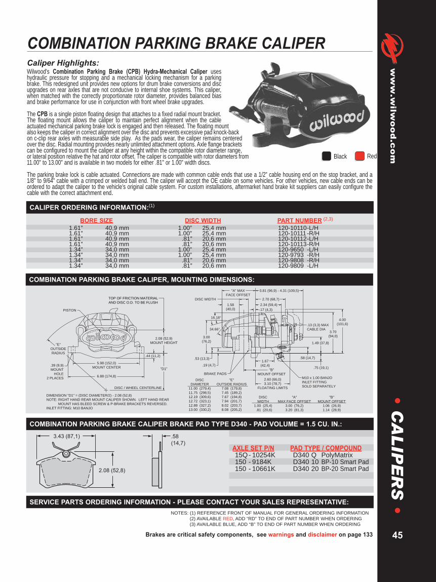
Brakes are critical safety components, see warnings and disclaimer on page 133
www.wilw
ood.com
45
•C
AL
IPE
RS
•COMBINATION PARKING BRAKE CALIPERCaliper Highlights:Wilwood's Combination Parking Brake (CPB) Hydra-Mechanical Caliper useshydraulic pressure for stopping and a mechanical locking mechanism for a parkingbrake. This redesigned unit provides new options for drum brake conversions and discupgrades on rear axles that are not conducive to internal shoe systems. This caliper,when matched with the correctly proportionate rotor diameter, provides balanced biasand brake performance for use in conjunction with front wheel brake upgrades.
The CPB is a single piston floating design that attaches to a fixed radial mount bracket.The floating mount allows the caliper to maintain perfect alignment when the cableactuated mechanical parking brake lock is engaged and then released. The floating mountalso keeps the caliper in correct alignment over the disc and prevents excessive pad knock-backon c-clip rear axles with measurable side play. As the pads wear, the caliper remains centeredover the disc. Radial mounting provides nearly unlimited attachment options. Axle flange bracketscan be configured to mount the caliper at any height within the compatible rotor diameter range,or lateral position relative the hat and rotor offset. The caliper is compatible with rotor diameters from11.00" to 13.00" and is available in two models for either .81" or 1.00" width discs.
The parking brake lock is cable actuated. Connections are made with common cable ends that use a 1/2” cable housing end on the stop bracket, and a1/8" to 9/64" cable with a crimped or welded ball end. The caliper will accept the OE cable on some vehicles. For other vehicles, new cable ends can beordered to adapt the caliper to the vehicle's original cable system. For custom installations, aftermarket hand brake kit suppliers can easily configure thecable with the correct attachment end.
BORE SIZE DISC WIDTH PART NUMBER (2,3)
1.61” 40,9 mm 1.00” 25,4 mm 120-10110-L/H1.61” 40,9 mm 1.00” 25,4 mm 120-10111-R/H1.61” 40,9 mm .81” 20,6 mm 120-10112-L/H1.61” 40,9 mm .81” 20,6 mm 120-10113-R/H1.34” 34,0 mm 1.00” 25,4 mm 120-9650 -L/H1.34” 34,0 mm 1.00” 25,4 mm 120-9793 -R/H1.34” 34,0 mm .81” 20,6 mm 120-9808 -R/H1.34” 34,0 mm .81” 20,6 mm 120-9809 -L/H
CALIPER ORDERING INFORMATION:(1)
NOTES: (1) REFERENCE FRONT OF MANUAL FOR GENERAL ORDERING INFORMATION(2) AVAILABLE RED, ADD “RD” TO END OF PART NUMBER WHEN ORDERING(3) AVAILABLE BLUE, ADD “B” TO END OF PART NUMBER WHEN ORDERING
5.98 (152,0)
MOUNT CENTER
6.88 (174,8)
DISC / WHEEL CENTERLINE
.39 (9,9)
MOUNT
HOLE
2 PLACES
2.08 (52,9)
MOUNT HEIGHT"E"
OUTSIDE
RADIUS
"D1"
.17 (4,3)
1.58
(40,0)
1.67
(42,4)
3.00
(76,2)
2.34 (59,4)
.53 (13,3) .58 (14,7)
.75 (19,1)
1.49 (37,8)
4.00
(101,6)
3.70
(94,0)
.19 (4,7)
"A" MAX
FACE OFFSET
3.81 (96,9) - 4.31 (109,5)
BRAKE PADSM10 x 1.00 BANJO
INLET FITTING
SOLD SEPARATELY
.13 (3,3) MAX
CABLE DIA
2.60 (66,0)
3.10 (78,7)
FLOATING LIMITS
2.70 (68,7)DISC WIDTH
16.18°
34.66°
.44 (11,2)
DIMENSION "D1" = (DISC DIAMETER/2) - 2.08 (52,8)
NOTE: RIGHT HAND REAR MOUNT CALIPER SHOWN. LEFT HAND REAR
MOUNT HAS BLEED SCREW & P-BRAKE BRACKETS REVERSED.
INLET FITTING: M10 BANJO
PISTON
DISC
DIAMETER
11.00 (279,4)
11.75 (298,5)
12.19 (309,6)
12.72 (323,1)
12.88 (327,2)
13.00 (330,2)
"E"
OUTSIDE RADIUS
7.08 (179,8)
7.45 (189,2)
7.67 (194,8)
7.94 (201,7)
8.02 (203,7)
8.08 (205,2)
"A"
MAX FACE OFFSET
3.00 (76,2)
3.20 (81,3)
DISC
WIDTH
1.00 (25,4)
.81 (20,6)
"B"
MOUNT OFFSET
1.06 (26,9)
1.14 (28,9)
"B"
MOUNT OFFSET
TOP OF FRICTION MATERIAL
AND DISC O.D. TO BE FLUSH
COMBINATION PARKING BRAKE CALIPER, MOUNTING DIMENSIONS:
SERVICE PARTS ORDERING INFORMATION - PLEASE CONTACT YOUR SALES REPRESENTATIVE:
.58
(14,7)
3.43 (87,1)
2.08 (52,8)
AXLE SET P/N PAD TYPE / COMPOUND15Q- 10254K D340 Q PolyMatrix150 - 9184K D340 10 BP-10 Smart Pad150 - 10661K D340 20 BP-20 Smart Pad
COMBINATION PARKING BRAKE CALIPER BRAKE PAD TYPE D340 - PAD VOLUME = 1.5 CU. IN.:
Black Red
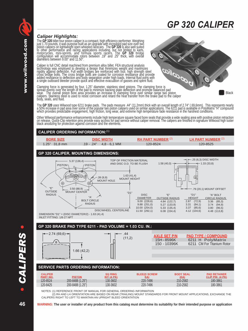
WARNING: The user or installer of any product from this catalog must determine its suitability for their intended purpose or application
www.wilwood.com
46
•C
AL
IPE
RS
•GP 320 CALIPER
Caliper Highlights:The GP 320 billet four piston caliper is a compact, high efficiency performer. Weighingjust 1.70 pounds, it was purpose built as an upgrade with increased pad size over twopiston calipers on lightweight open wheeled racecars. The GP 320 is also well suitedto other performance and racing applications including, but not limited to karts,motorcycles, mini-sprints, and formula sports racers. The GP 320 bridgeconfiguration will accommodate rotors between .19" and .25" thick, with overalldiameters between 9.00" and 11.50".Caliper is full CNC detail machined from premium alloy billet. FEA structural analysistechnology was employed to develop a design that minimizes weight and maximizesrigidity against deflection. Full width bridges are reinforced with four, high strength steelcross bridge bolts. The cross bridge bolts are coated for corrosion resistance and provideadded resistance to deflection and body separation under high loads. Internal fluid ports witha single outboard bleeder provide quick and effective evacuation of gasses and spent fluid.Clamping force is generated by four, 1.25" diameter, stainless steel pistons. The clamping force isspread evenly over the length of the pad to minimize backing plate deflection and promote balanced padwear. The overall piston bore area provides an increase in clamping force over similar range two pistoncalipers. Stainless steel is used to resist corrosion and retard the heat transfer from the brake pad to the caliperbody, seals, and fluid.The GP 320 uses Wilwood type 6211 brake pads. The pads measure .44" (11,2mm) thick with an overall length of 2.74" ( 69,6mm). This represents nearlya 50% increase in pad area over some of the popular two piston calipers used on similar applications. The 6211 pad is available in PolyMatrix "H" compoundwhich provides predictable engagement, high friction, long wear, and extreme high temperature fade resistance in the harshest conditions.Other Wilwood performance enhancements include high temperature square faced bore seals that provide a wide sealing area with positive piston retractionon release. Quick-Clip retention pins provide easy access for pad service without caliper removal. The calipers are finished in signature Wilwood high lusterblack anodizing for protection against corrosion and the elements.
NOTES: (1) REFERENCE FRONT OF MANUAL FOR GENERAL ORDERING INFORMATION(2) RH AND LH ORIENTATION ARE BASED ON REAR (TRAILING) MOUNT STANDARDS FOR FRONT MOUNT APPLICATIONS, EXCHANGE THE
CALIPERS RIGHT TO LEFT TO MAINTAIN AN UPRIGHT BLEED ORIENTATION
BORE SIZE DISC WIDTH RH PART NUMBER (2) LH PART NUMBER (2)
1.25” 31,8 mm .19 - .24” 4,8 - 6,1 MM 120-8524 120-8525
CALIPER ORDERING INFORMATION:(1)
Black
"D1"
5.37 (136,4)
PISTONPISTON1.58 (40,0) 1.33 (33,8)
1.63 (41,4)
MOUNT HEIGHT
.25 (6,3) DISC WIDTH
.79 (20,1) MOUNT OFFSET
.39 (9,9)
MOUNT HOLE
3.50 (88,9)
MOUNT CENTER
"E"
OUTSIDE
RADIUS
DISC/WHEEL CENTERLINE
"A'
BOLT CIRCLE
RADIUS
DIMENSION "D1" = (DISC DIAMETER/2) - 1.63 (41,4)
INLET FITTING: 1/8-27 NPT
TOP OF FRICTION MATERIAL
AND DISC O.D. TO BE FLUSH
DISC
DIAMETER
9.00 (228,6)
9.88 (251,0)
10.00 (254,0)
11.50 (292,1)
"E"
OUTSIDE RADIUS
4.84 (122,7)
5.27 (133,9)
5.33 (135,4)
6.08 (154,4)
"D1"
HEIGHT
2.87 (72,9)
3.31 (84,1)
3.37 (85,6)
4.12 (104,6)
"A" BOLT
CIRCLE RADIUS
3.36 (85,3)
3.74 (94,9)
3.80 (96,5)
4.48 (113,8)
GP 320 CALIPER, MOUNTING DIMENSIONS:
.44
(11,2)
2.74 (69,6)
1.66 (42,2)
AXLE SET P/N PAD TYPE / COMPOUND15H - 8596K 6211 H PolyMatrix150 - 10396K 6211 CM For Titanium Rotor
GP 320 BRAKE PAD TYPE 6211 - PAD VOLUME = 1.03 CU. IN.:
CALIPER SQ RING BLEE(D SCREW BODY SEAL PAD RETAINERPART NO. PISTON KIT (4 PK) EA) (EA) CLIP PIN (4 PK)120-8524 200-8488 (1.25”) 130-3602 220-7496 210-2582 180-3861120-8425 200-8488 (1.25”) 130-3602 220-7496 210-2582 180-3861
SERVICE PARTS ORDERING INFORMATION:
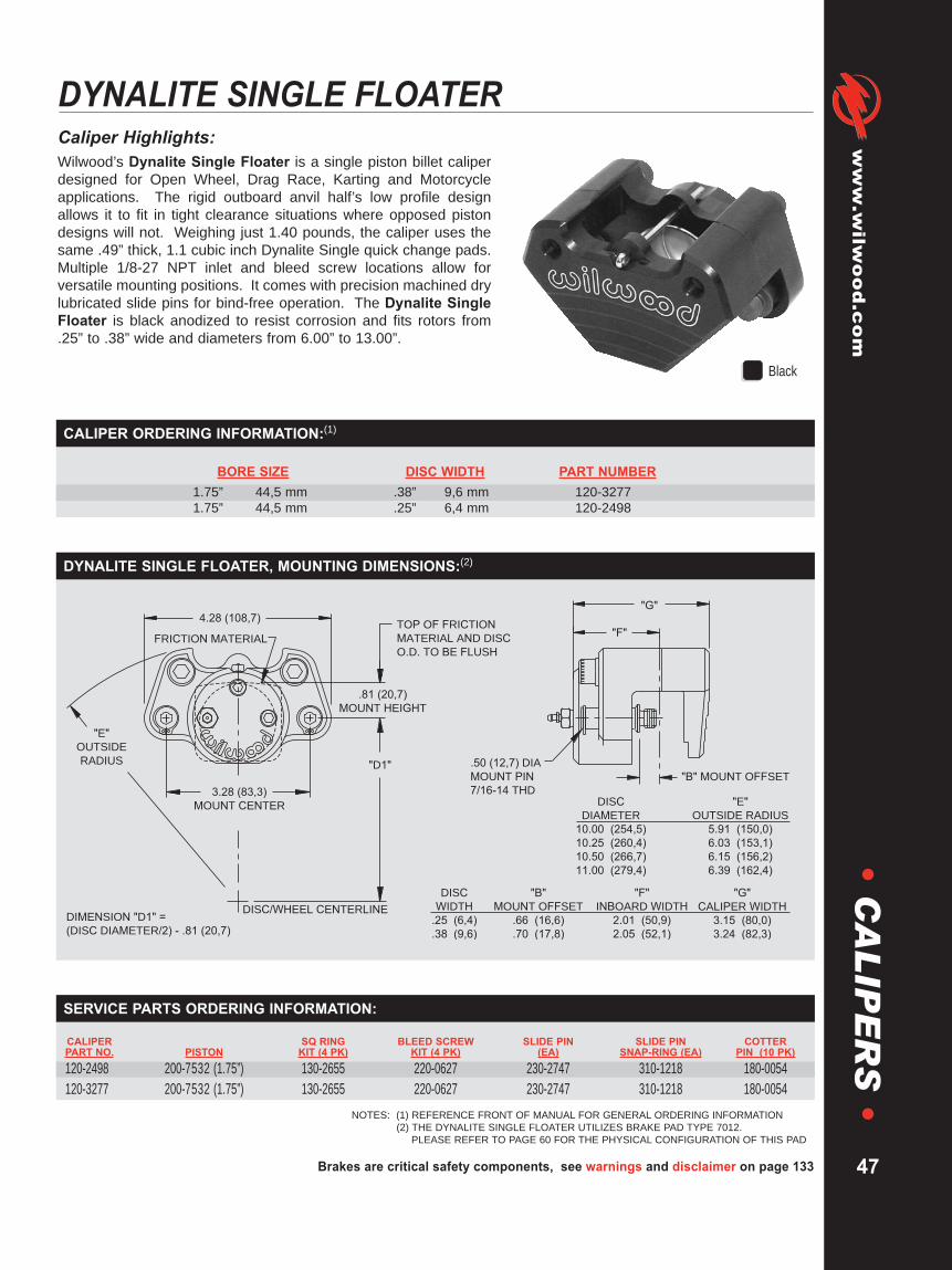
Brakes are critical safety components, see warnings and disclaimer on page 133
www.wilw
ood.com
47
•C
AL
IPE
RS
•DYNALITE SINGLE FLOATERCaliper Highlights:Wilwood’s Dynalite Single Floater is a single piston billet caliperdesigned for Open Wheel, Drag Race, Karting and Motorcycleapplications. The rigid outboard anvil half’s low profile designallows it to fit in tight clearance situations where opposed pistondesigns will not. Weighing just 1.40 pounds, the caliper uses thesame .49” thick, 1.1 cubic inch Dynalite Single quick change pads.Multiple 1/8-27 NPT inlet and bleed screw locations allow forversatile mounting positions. It comes with precision machined drylubricated slide pins for bind-free operation. The Dynalite SingleFloater is black anodized to resist corrosion and fits rotors from.25” to .38” wide and diameters from 6.00” to 13.00”.
BORE SIZE DISC WIDTH PART NUMBER1.75” 44,5 mm .38” 9,6 mm 120-32771.75” 44,5 mm .25” 6,4 mm 120-2498
CALIPER ORDERING INFORMATION:(1)
NOTES: (1) REFERENCE FRONT OF MANUAL FOR GENERAL ORDERING INFORMATION(2) THE DYNALITE SINGLE FLOATER UTILIZES BRAKE PAD TYPE 7012.
PLEASE REFER TO PAGE 60 FOR THE PHYSICAL CONFIGURATION OF THIS PAD
"G"
"F"
4.28 (108,7)
"E"
OUTSIDE
RADIUS
FRICTION MATERIAL
.81 (20,7)
MOUNT HEIGHT
DISC/WHEEL CENTERLINEDIMENSION "D1" =
(DISC DIAMETER/2) - .81 (20,7)
.50 (12,7) DIA
MOUNT PIN
7/16-14 THD
"B" MOUNT OFFSET
DISC
DIAMETER
10.00 (254,5)
10.25 (260,4)
10.50 (266,7)
11.00 (279,4)
"E"
OUTSIDE RADIUS
5.91 (150,0)
6.03 (153,1)
6.15 (156,2)
6.39 (162,4)
DISC
WIDTH
.25 (6,4)
.38 (9,6)
"B"
MOUNT OFFSET
.66 (16,6)
.70 (17,8)
"F"
INBOARD WIDTH
2.01 (50,9)
2.05 (52,1)
"G"
CALIPER WIDTH
3.15 (80,0)
3.24 (82,3)
3.28 (83,3)
MOUNT CENTER
TOP OF FRICTION
MATERIAL AND DISC
O.D. TO BE FLUSH
"D1"
DYNALITE SINGLE FLOATER, MOUNTING DIMENSIONS:(2)
CALIPER SQ RING BLEED SCREW SLIDE PIN SLIDE PIN COTTERPART NO. PISTON KIT (4 PK) KIT (4 PK) (EA) SNAP-RING (EA) PIN (10 PK)120-2498 200-7532 (1.75”) 130-2655 220-0627 230-2747 310-1218 180-0054120-3277 200-7532 (1.75”) 130-2655 220-0627 230-2747 310-1218 180-0054
SERVICE PARTS ORDERING INFORMATION:
Black

WARNING: The user or installer of any product from this catalog must determine its suitability for their intended purpose or application
www.wilwood.com
48
•C
AL
IPE
RS
•KART/JR. DRAGSTER CALIPER • PS-1 CALIPER
NOTES: (1) REFERENCE FRONT OF MANUAL FOR GENERAL ORDERING INFORMATION
PS-1 Highlights:The PS-1 Caliper is compact, lightweight (.93 pounds) and combinesthe strength of cast aluminum construction with a sleek low profiledesign. This caliper utilizes two stainless steel deep cup pistons tominimize heat transfer from the .30” thick pad to the brake fluid whileemploying high temperature square piston seals to control pistonretraction. Internal crossover brake fluid passages eliminate the useof external crossover tubes. The PS-1 fits rotors with diametersranging from 6.00” to 9.00”, thickness sizes from .15” to .20”.
BORE SIZE DISC WIDTH MOUNT HOLE INLET P/N • RH P/N • LH1.12” 28,4 mm .20” 5,1 mm M8 x 1.25 M10 x 1.25 120-8373 120-83741.00” 25,4 mm .20” 5,1 mm .32” 1/8-27 NPT 120-5453 120-5456
MOUNT HOLE
INLETFITTING
MOUNTINGBOSS.80 (20,3) DIA .83 (21,1)
MOUNTOFFSET
.41 (10,4) EARTHICKNESS
.19 (4,8) DISC WIDTH BRAKE PAD - PAD VOLUME = .26 CU IN.TOP OF FRICTION MATERIAL AND DISC O.D. TO BE FLUSH
4.94 (125,5)OUTSIDE RADIUS
8.00 (203,2) ROTOR
3.79 (96,3)
"D1"
1.35(34,3)
1.09(27,7)
DISC / WHEEL CENTER LINE
DIMENSION "D1" = (DISC DIAMETER/2) - 1.22 (30,9) • NOTE: RIGHT HAND CALIPER SHOWN
1.22 (30,9)MOUNT HEIGHT
2.50 (63,5)MOUNT CENTER
1.00 (25,4)
.30(7,6)
2.66 (67,6)
AXLE SET P/N PAD TYPE / COMPOUND150 - 4091K PS-1 SINTERED METALLIC
Kart/Jr. Dragster Highlights:Our Kart/Jr. Dragster Caliper is designed specifically for racing. Aunique self retracting and adjusting piston system has beenincorporated which enables the piston to retract as the brake linepressure is reduced. The caliper can be mounted on either side of thevehicle and comes in three rotor widths. At just 1.20 pounds, thecaliper comes with high performance, high friction brake pads.Additional features include deep cup stainless steel piston for reducedheat transfer, cotter pin, pad retainer, internal fluid passage and blueanodized finish. A specifically designed master cylinder is alsoavailable for use with this caliper (see page 105).
BORE SIZE DISC WIDTH PART NUMBER1.00” 25,4 mm .12” 3,0 mm 120-54981.00” 25,4 mm .18” 4,6 mm 120-57501.00” 25,4 mm .50” 12,7 mm 120-5499
3.18 (80,8)
2.25 (57,2)
MOUNT CENTER
"D1"
.19 (4,8)
MOUNT
HEIGHT
1.23 (31,3)
COMPRESSION FITTING
1.23
(31,3)
BRAKE PAD - PAD VOLUME = .34 CU IN.
1.38
(35,1)
DISC/WHEEL CENTERLINE
TOP OF FRICTION
MATERIAL AND DISC
O.D. TO BE FLUSH
.39 (9,9)
MOUNT
HOLE
DISC WIDTH
"B"
MOUNT
OFFSET
DISC
DIAMETER
8.00 (203,2)
8.00 (203,2)
8.75 (222,3)
DISC
WIDTH
.12 (3,05)
.18 (4,6)
.50 (12,7)
"B"
MOUNT OFFSET
1.32 (33,5)
1.36 (34,5)
1.51 (38,4)DIMENSION "D1" = (DISC DIAMETER/2) + .19 (4,8)
1.03 (26,2)
.30
(7,6)
2.32 (59,0)
AXLE SET P/N PAD TYPE / COMPOUND
150 - 5602K SINTERED METALLIC (2 pk)
150 - 5472K SINTERED METALLIC (ea)
KA
RT/
JR.D
RA
GST
ERC
ALI
PER(1)
PS-1
CA
LIPE
R(1)

Brakes are critical safety components, see warnings and disclaimer on page 133
www.wilw
ood.com
49
•C
AL
IPE
RS
•GM III CALIPER
NOTES: (1) REFERENCE FRONT OF MANUAL FOR GENERAL ORDERING INFORMATION(2) THE BASE PART NUMBER CAN BE RIGHT HAND OR LEFT HAND MOUNTED(3) SLIDE PIN KIT P/N 230-0619 IS REQUIRED FOR INSTALLATION AND MUST BE ORDERED SEPARATELY(4) INCLUDES SLIDE PIN VIBRATION DAMPENERS(5) THIS PISTON IS NOT COMPATIBLE WITH THE EARLIER BLACK ANODIZED VERSIONS OF THE GM II AND GM III CALIPERS.
ALL BLACK ANODIZED 2.75” BORE CALIPERS REQUIRE PISTON P/N 200-1120
Caliper Highlights:Wilwood’s GM III caliper represents the latest refinements in caliper design andmanufacturing through solid modeling and stress simulation programs. The result is the mostrigid, highest torque, lightweight aluminum caliper with weights starting at 3.36 pounds.The real strength comes from its exclusive triple bridge configuration which provides atremendous increase in clamping force over other twin bridge calipers. Efficient designsfurther maximize weight savings: material is properly placed to fortify all load bearing points.Each caliper model has its own unique casting: 2.38” diameter piston calipers incorporate asmaller external contour than the larger 2.75” diameter piston calipers. Any material that didnot contribute to strength, was eliminated for weight reduction.The GM III incorporates standard Wilwood features like stainless steel pistons for increased fluidprotection and high temperature seals for controlled retraction which provides improved driver feel. The GM IIIfor 1.00” width rotor is machined and fitted with OEM type slide pin vibration dampeners for a direct OEM caliperinterchange.These tight grained, high density aircraft alloy aluminum castings are fully machined, assembled and tested in-house by fully trained technicians at Wilwood to assuretop quality and peak performance.
BORE SIZE DISC WIDTH PART NUMBER (2, 3)
2.75” 69,8 mm 1.25” 31,8 mm 120-52892.75” 69,8 mm 1.00” 25,4 mm 120-5861(4)2.75” 69,8 mm 1.00” 25,4 mm 120-5862-P(4)2.75” 69,8 mm .81” 20,6 mm 120-52882.38” 60,4 mm 1.25” 31,8 mm 120-53442.38” 60,4 mm .81” 20,6 mm 120-5343
CALIPER ORDERING INFORMATION:(1)
CALIPER O-RING BLEED SCREW SLIDE PINPART NO. PISTON KIT (4 PK) KIT (4 PK) KIT (4 PK)120-5288 P 200-6633 (2.75”) (5) 130-4955 220-0627 230-0619120-5289 P 200-6633 (2.75”) (5) 130-4955 220-0627 230-0619120-5343 P 200-1119 (2.38”) (5) 130-4956 220-0627 230-0619120-5344 P 200-1119 (2.38”) (5) 130-4956 220-0627 230-0619120-5861 P 200-6633 (2.75”) (5) 130-4955 220-0627 230-0619120-5862-P 200-6633 (2.75”) (5) 130-4955 220-0627 230-0619
SERVICE PARTS ORDERING INFORMATION:
GM "INNER" PAD
2.08
(52,8)
.58
(14,7)
5.35 (135,9)
GM "OUTER" PAD
2.41
(61,2)
.52
(13,2)
7.77 (197,4)
AXLE SET P/N PAD TYPE / COMPOUND15A - 5737K D52 A PolyMatrix15B - 3994K D52 B PolyMatrix15C - 4419K D52 C PolyMatrix15E - 6102K D52 E PolyMatrix15H - 8232K D52 H PolyMatrix15Q- 6830K D52 Q PolyMatrix150 - 8939K D52 10 BP-10 Smart Pad150 - 9421K D52 20 BP-20 Smart Pad150 - 9866K D52 30 BP-30 Smart Pad
GM III BRAKE PAD TYPE D52 - PAD VOLUME “INNER” = 3.9 CU. IN. / PAD VOLUME “OUTER” = 3.8 CU. IN.:
.69 (17,5)
MOUNT
HOLE
.77 (19,6)
MOUNT HEIGHT
TOP OF FRICTION
MATERIAL AND DISC
O.D. TO BE FLUSH
8.18 (207,8)DISC WIDTH
2.56 (65,0) 1.57 (39,9)
"B" MOUNT OFFSET"E"
OUTSIDE
RADIUS
7.05 (179,1)
MOUNT CENTER
"D1"
DISC/WHEEL CENTERLINE DISC
WIDTH
.81 (20,6)
1.00 (25,4)
1.25 (31,8)
"B"
MOUNT OFFSET
1.50 (38,1)
1.72 (43,7)
1.72 (43,7)
"E"
OUTSIDE RADIUS
6.69 (169,9)
7.04 (178,8)
DISC
DIAMETER
11.00 (279,4)
11.75 (298,5)DIMENSION "D1" = (DISC DIAMETER/2) - .77 (19,6) CALIPER MOVES INWARD AS PAD WEARS, .35 (8,9) MAX
NOTE: R/H CALIPER SHOWN, L/H HAS BLEED SCREW REVERSED. INLET FITTING: 1/8-27 NPT
GM III CALIPER, MOUNTING DIMENSIONS:

WARNING: The user or installer of any product from this catalog must determine its suitability for their intended purpose or application
www.wilwood.com
50
•C
AL
IPE
RS
•GM METRIC CALIPER
Caliper Highlights:Wilwood’s GM Metric Caliper is a direct replacement for the 1978 and later D154 typeGM metric caliper. Weights starting at 2.92 pounds, it provides a substantial weightsavings over cast iron OE calipers.This competition caliper represents the latest refinements in caliper design andmanufacturing through the use of computer based FEA solid modeling and stresssimulation programs. The real strength of this caliper comes from its triple bridgeconfiguration, and its lightness is a result of efficient design.The triple bridge provides higher clamping efficiency through lower deflection over all twinbridge models. All load bearing and stress points are fortified to maximize strength, andall unnecessary material is removed to maximize weight reduction. The results are thestrongest, lightest, and most efficient aluminum caliper in its class.The caliper body is a precision casting using a tight grained, high density aircraft alloy. Stainless steelpistons provide improved fluid protection with high resistance to corrosion and low heat transfer. Eachcaliper is fully machined, assembled with high temperature seals, and tested in-house.
NOTES: (1) REFERENCE FRONT OF MANUAL FOR GENERAL ORDERING INFORMATION(2) THE BASE PART NUMBER CAN BE RIGHT HAND OR LEFT HAND MOUNTED(3) SLIDE PIN KIT P/N 230-0619 IS REQUIRED FOR INSTALLATION AND MUST BE ORDERED SEPARATELY(4) INCLUDES SLIDE PIN VIBRATION DAMPENERS
BORE SIZE DISC WIDTH PART NUMBER (2,3)
2.38” 60,4 mm 1.25” 31,8 mm 120-64272.38” 60,4 mm 1.00” 25,4 mm 120-7197 (4)2.38” 60,4 mm .81” 20,6 mm 120-6426
CALIPER ORDERING INFORMATION:(1)
CALIPER O-RING BLEED SCREW SLIDE PINPART NO. PISTON KIT (4 PK) KIT (4 PK) KIT (4 PK)120-6426 200-1119 (2.38”) 130-4956 220-0627 230-0619120-6427 200-1119 (2.38”) 130-4956 220-0627 230-0619120-7197 200-1119 (2.38”) 130-4956 220-0627 230-0619
SERVICE PARTS ORDERING INFORMATION:
.67 (17,0)
.52
(13,2)4.96 (126,0)
GM "INNER" PAD
.52
(13,2)
4.89 (124,2)
2.56
(65,0)
GM “INNER” PAD
GM “OUTER” PAD
AXLE SET P/N PAD TYPE / COMPOUND15A - 6219K D154 A PolyMatrix15B - 3998K D154 B PolyMatrix15C - 4420K D154 C PolyMatrix15E - 6103K D154 E PolyMatrix15Q- 6831K D154 Q PolyMatrix150 - 8936K D154 10 BP-10 Smart Pad150 - 9422K D154 20 BP-20 Smart Pad
GM METRIC BRAKE PAD TYPE D154 - PAD VOLUME “INNER” = 2.7 CU. IN. / - PAD VOLUME “OUTER” = 3.2 CU. IN.:
.69 (17,5)
MOUNT
HOLE
.48 (12,2)
MOUNT HEIGHT
TOP OF FRICTION MATERIAL
AND DISC O.D. TO BE FLUSH6.71 (170,4)DISC WIDTH
2.62 (66,5) 1.47
(37,3)
"B"
MOUNT OFFSET"E"
OUTSIDE
RADIUS
5.46 (138,7)
MOUNT CENTER
"D1"
DISC/WHEEL CENTERLINE
DIMENSION "D1" = (DISC DIAMETER/2) - .48 (12,2)
CALIPER MOVES INWARD AS PAD WEARS, .35 (8,9) MAX
NOTE: RIGHT HAND CALIPER SHOWN, LEFT HAND HAS BLEED SCREW REVERSED
INLET FITTING: 1/8-27 NPT
"E"
OUTSIDE RADIUS
6.55 (166,4)
6.90 (175,3)
DISC
DIAMETER
11.00 (279,4)
11.75 (298,5)
DISC
WIDTH
.81 (20,6)
1.00 (25,4)
1.25 (31,8)
"B"
MOUNT OFFSET
1.74 (44,2)
1.84 (46,7)
1.96 (49,8)
GM METRIC CALIPER, MOUNTING DIMENSIONS:

Brakes are critical safety components, see warnings and disclaimer on page 133
www.wilw
ood.com
51
•C
AL
IPE
RS
•NOTES: (1) REFERENCE FRONT OF MANUAL FOR GENERAL ORDERING INFORMATION(2) THE CALIPER PART NUMBERS ARE THE SAME FOR LEFT OR RIGHT MOUNTING. BLEED SCREW AND INLET FITTINGS MUST BE
INSTALLED IN THE CORRECT POSITION DURING ASSEMBLY ON THE VEHICLE.(3) CALIPER SLIDE PIN BOLTS, P/N 230-0619 (4 BOLTS PER KIT) ARE REQUIRED FOR INSTALLATION AND MUST BE ORDERED SEPARATELY.(4) THESE CALIPERS INCLUDE SLIDE PIN VIBRATION DAMPERS.
GM IRON METRIC CALIPERCaliper Highlights:These all new cast, not rebuilt iron calipers are bolt-on replacements for 1978 and later GM Metriccalipers widely used in "spec" racing categories and low cost disc brake conversions.Wilwood iron GM Metric calipers combine new part quality with modern machining precision. Thereare two piston size options to assist builders with properly building static bias into a car. Previously,builders using the metric calipers generally had to mount the same size calipers on all four wheels.This drastically limited the tuning options and often created front to rear bias ratios that were notconducive to good handling and stability under hard braking. Some builders, and other brakesuppliers, chose to offer re-machined OE calipers to provide a bias tuning option. Unfortunately, re-machining a used casting that was never designed for the larger bore size, can create realcompromises in strength, reliability, and performance.To address these needs, Wilwood has tooled two separate castings that are fitted with either 2.75" or 2.00" stainlesssteel pistons and high temperature bore seals. Each casting is designed specific for its intended bore size. The calipers arestrong and precise, without unnecessary added weight from oversized castings. The stainless steel pistons resist corrosion while helping to slow the heat transfer fromthe pads. The high temperature seals provide long service life when used in hard braking applications and maintain their resilience to provide positive piston retractionon release. In addition to the optional piston sizes, two models are available with slide pin vibration dampers installed to help reduce rattle and other noise.All Wilwood GM Metric Calipers use the standard D154 type brake pads. The complete range of Wilwood high performance and racing pad compounds is availableto match response, friction, and temperature range to any application.
BORE SIZE DISC WIDTH WEIGHT (LBS) PART NUMBER (2,3)
2.75” 69,9 mm 1.00” 24,4 mm 4.4 120-89242.75” 69,9 mm 1.00” 25,4 mm 4.4 120-8926(4)2.00” 50,8 mm 1.00” 25,4 mm 4.1 120-93332.00” 50,8 mm 1.00” 25,4 mm 4.1 120-9487(4)
CALIPER ORDERING INFORMATION:(1)
SERVICE PARTS ORDERING INFORMATION:
CALIPER O-RING BLEED SCREW SLIDE PINPART NO. PISTON KIT (4 PK) KIT (EA) KIT (4 PK)120-8924 200-6633 (2.75”) 130-4955 220-8932 230-0619120-8926 200-6633 (2.75”) 130-4955 220-8932 230-0619120-9333 200-9342 (2.00”) 130-0777 220-8932 230-0619120-9487 200-9342 (2.00”) 130-0777 220-8932 230-0619
.69 (17,5)MOUNTHOLE
.48 (12,2)MOUNT HEIGHT
TOP OF FRICTION MATERIALAND DISC O.D. TO BE FLUSH6.62 (168,1)
DISC WIDTH2.58 (65,5) 1.20 (30,5)
"B" MOUNT OFFSET"E"
OUTSIDERADIUS
5.46 (138,7)MOUNT CENTER
"D1"
DISC/WHEEL CENTERLINE
DIMENSION "D1" = (DISC DIAMETER/2) - .48 (12,2) CALIPER MOVES INWARD AS PAD WEARS, .35 (8,9) MAXNOTE: R/H CALIPER SHOWN, L/H HAS BLEED SCREW REVERSED. INLET FITTING: M10 x 1.5
"E"OUTSIDE RADIUS
6.55 (166,4)6.90 (175,3)
DISCDIAMETER
11.00 (279,4)11.75 (298,5)
DISCWIDTH
1.00 (25,4)
"B"MOUNT OFFSET
1.85 (47,0)
GM IRON METRIC CALIPER, MOUNTING DIMENSIONS:
.67 (17,0)
.52
(13,2)4.96 (126,0)
GM "INNER" PAD
.52
(13,2)
4.89 (124,2)
2.56
(65,0)
GM “INNER” PAD
GM “OUTER” PAD
AXLE SET P/N PAD TYPE / COMPOUND15A - 6219K D154 A PolyMatrix15B - 3998K D154 B PolyMatrix15C - 4420K D154 C PolyMatrix15E - 6103K D154 E PolyMatrix15Q- 6831K D154 Q PolyMatrix150 - 8936K D154 10 BP-10 Smart Pad150 - 9422K D154 20 BP-20 Smart Pad
GM IRON METRIC BRAKE PAD TYPE D154 - PAD VOLUME “INNER” = 2.7 CU. IN. / - PAD VOLUME “OUTER” = 3.2 CU. IN.:

WARNING: The user or installer of any product from this catalog must determine its suitability for their intended purpose or application
www.wilwood.com
52
•C
AL
IPE
RS
•GP SERIES MOTORCYCLE CALIPERS
Caliper Highlights:Wilwood's GP 300, GP 300RT, GP 310 and GP 340 motorcycle disc brake calipers have beendesigned and engineered for use on 1984 - present Harley-Davidson® Motorcycles. Built around a4-piston, high performance powerhouse, these billet aluminum calipers bring distinctive, bolt-onstyling: Direct leg-mounted calipers are available for all single and dual disc models (except Springerand 4-speed FL models), as well as the 1983 XR 1000.
Rear calipers are available for all Softail®, Dyna, and touring models, utilizing unique bracket designsthat combine the right elements of strength and style.
The GP 310 and GP 300 calipers are available in polished, brilliant chrome or red finishes, with the added performancecharacteristics found in Wilwood's racing calipers: stainless steel pistons to reduce brake fade while resisting corrosion andhigh temperature piston seals for extended life, controlled retraction and drag free operation. Additional features includebright-finish bleed screws and hardware, exclusive pad anti-rattle clip, and brake pads designed to operate in the widestrange of temperatures and environments, utilizing our industry leading stainless steel rotor compatible formulation.
Polished
Chrome
Red
Black
*
DESCRIPTION PART NUMBERGP 300 and GP 310 Brake Pads (caliper set) 150-8733-2GP 300 and GP 310 Seal Kit 130-3602
SERVICE PARTS ORDERING INFORMATION:
GP 300 FRONT / REAR MOTORCYCLE CALIPER ORDERING INFORMATION:
DESCRIPTION POLISHED CHROME BLACKFront Left Hand Caliper (single) 1984-1999 120-3933-P 120-4243Front Right Hand Caliper 1984-1999 120-3945-P 120-4242Optional Mounting Bolt Kit, P/N: 230-4237Rear Caliper (bracket not included) 1984-1999 120-3935-P 120-4244Rear Softail® Bracket Kit (shown with caliper lower right) 1984-1999 250-4235
DESCRIPTION POLISHED CHROMEFront Right Hand Caliper 2000-Up 120-10369-P 120-10369Front Left Hand Caliper 2000-Up 120-10370-P 120-10370Rear Caliper 2000-Up 120-10001-P 120-10001
GP 300RT FRONT / REAR MOTORCYCLE CALIPER ORDERING INFORMATION:
NOTES: HARLEY-DAVIDSON® MOTORCYCLES SPECIFIES USE OF DOT 5 SILICONE BRAKE FLUID BECAUSE OF ITS MINIMIZED IMPACT ON PAINTED SURFACES.WILWOOD DISC BRAKE CALIPERS WILL WORK WITH EITHER FLUID, BUT NEVER MIX DOT 5 SILICONE BRAKE FLUID WITH DOT 3, 4, OR 5.1 FLUIDS.
GP 300 Rear Caliper with Bracket (not included)GP 300 Front Caliper
GP 300 RT Rear Caliper Shown

Brakes are critical safety components, see warnings and disclaimer on page 133
www.wilw
ood.com
53
•C
AL
IPE
RS
•FRONT DESCRIPTION POLISHED CHROME RED BLACKFront Left Hand Caliper (single) 1984-1999 120-7737-P 120-7737 120-7737-RD 120-7737-BKFront Right Hand Caliper 1984-1999 120-7736-P 120-7736 120-7736-RD 120-7736-BKOptional Mounting Bolt Kit, P/N: 230-4237Front Left Hand Caliper (single) 2000-Present 120-7739-P 120-7739 120-7739-RD 120-7739-BKFront Right Hand Caliper 2000-Present 120-7738-P 120-7738 120-7738-RD 120-7738-BKOptional Mounting Bolt Kit, P/N: 230-6330
REAR DESCRIPTION (Bracket Not Included)Rear Right Hand Caliper (Std 3.50” Mount) 120-7740-P 120-7740 120-7740-RD 120-7740-BKRear Left Hand Caliper (Std 3.50” Mount) (1) 120-7741-P 120-7741 120-7741-RD 120-7741-BKRear Right Hand Caliper - Sprocket Brake 120-10175-P 120-10175 120-10175-RD 120-10175-BKRear Left Hand Caliper - Sprocket Brake 120-10174-P 120-10174 120-10174-RD 120-10174-BKOptional Mounting Bolt Kit, P/N: 230-4236
NOTE: (1) USE WITH DYNA “BOTTOM” BRACKET
GP 310 FRONT / REAR MOTORCYCLE CALIPER ORDERING INFORMATION:
GP 310 Rear CaliperGP 310 Front Caliper
DESCRIPTION POLISHED CHROMEFront Right Hand Caliper 1984-99 — 120-10473Front Left Hand Caliper 1984-99 — 120-10474Front Right Hand Caliper 2000-Up — 120-10099Front Left Hand Caliper 2000-Up — 120-10100Rear Caliper 1984-Up — 120-10101
GP 340 FRONT / REAR MOTORCYCLE CALIPER ORDERING INFORMATION:
GP 340 RT Front Caliper Shown
DISC ROTATION"B"
TOP OF FRICTION
MATERIAL AND DISC
O.D. TO BE FLUSH
.20 (5,1) DISC WIDTH
*FRONT: 2000-UP, REAR: 1984-UP
1.02
(25,9)
.95
(24,1)
"F"
MOUNT
HOLE
"C"
MOUNT CENTER
"A"
OUTSIDE RADIUS
"A"7.21 (183,1)7.17 (182,1)6.83 (173,5)6.83 (173,5)
"B"6.48 (164,1)6.39 (162,3)6.28 (159,5)6.31 (160,3)
"C"3.44 (87,4)3.44 (87,4)2.72 (69,1)2.72 (69,1)
"D"2.33 (59,2)2.33 (59,2)2.18 (55,4)2.18 (55,4)
"E"2.46 (62,5)2.46 (62,5)1.99 (50,5)1.99 (50,5)
"G".87 (22,1).87 (22,1)
1.31 (33,3)1.31 (33,3)
"H"3.27 (83,1)3.27 (83,1)3.16 (80,3)3.16 (80,3)
"I"3.43 (86,7)3.42 (86,7)3.57 (90,7)3.57 (90,7)
"J".53 (13,5).53 (13,5).78 (19,8).78 (19,8)
"F"3/8-16 THD3/8-16 THDM10 x 1.5M10 x 1.5
CALIPERGP 300 (1984-99)GP 310 (1984-99)GP 310 (2000-UP)GP 340*
"G"
"H"
"I"
DISC CENTERLINENOTE: RIGHT HAND CALIPER SHOWN
DIMENSIONS CORRECT WHEN USED WITH A 11.5 (292,1) DIA x .20 (5,1) DISC. OTHER MOUNTING DIMENSIONS AVAILABLE.
"J"
MOUNT
OFFSET
"E"
"D"
MOUNT
HEIGHT
GP 310, GP 300RT, GP 340 FRONT, GP 300 FRONT/REAR, MOTORCYCLE CALIPER, MOUNTING DIMENSIONS:

WARNING: The user or installer of any product from this catalog must determine its suitability for their intended purpose or application
www.wilwood.com
54
•C
AL
IPE
RS
•GP SERIES MOTORCYCLE CALIPERS / ROTORS
GP SERIES FRONT / REAR MIRROR POLISH ROTOR (MPR) ORDERING INFORMATION:
MIRROR POLISH ROTOR ORDERING INFORMATION:
GP 310 REAR BRACKET DESCRIPTION POLISHED CHROMESoftail® Bracket Kit 1984-1999 250-8035-P 250-8035Softail® Bracket Kit 2000-Present 250-8036-P 250-8036Dyna Bracket Kit 1984-1999 250-8034-P 250-8034Dyna Bracket Kit 2000-Present 250-8033-P 250-8033Dyna “Bottom” Bracket Kit (1) 1984-1999 250-8252-P 250-8252FLH / FLT Bracket Kit 2000-2006 250-10165-P 250-10165
Optional Mounting Bolt Kit, P/N: 230-4236 is included with brackets
NOTE: (1) LOCATES CALIPER ON THE BOTTOM SIDE OF THE ROTORUSE WITH LEFT HAND GP 310 REAR CALIPER
GP 310, GP 300RT, GP 340 REAR MOTORCYCLE CALIPER BRACKETS ORDERING INFORMATION:
DISC ROTATION TOP OF FRICTION
MATERIAL AND DISC O.D.
TO BE FLUSH
.20 (5,1) DISC WIDTH
1.08
(27,4)
.95
(24,1)
.39 (9,9)
MOUNT
HOLE
3.50 (88,9)
MOUNT CENTER
5.37 (136,4)
6.51 (165,4)
OUTSIDE RADIUS
4.55 (115,6)
BOLT CIRCLE
RADIUS
DISC CENTERLINENOTE: RIGHT HAND CALIPER SHOWN
DIMENSIONS CORRECT WHEN USED WITH A
11.5 (292,1) DIA x .20 (5,1) DISC.
OTHER MOUNTING DIMENSIONS AVAILABLE.
P
.70 (20,1)
MOUNT OFFSET
4.20
(106,7)
1.55 (39,4)
MOUNT
HEIGHT
GP 310, GP 300RT, GP 340 REAR MOTORCYCLE CALIPER, MOUNTING DIMENSIONS:
Wilwood mirror polished stainless (MPS) rotors combine theultimate in performance and distinctive style for productionbikes and full customs using OE dimension brakecomponents. A proprietary finishing process on a selectstainless alloy provides a second-to-none deep mirror finish,and the stopping power you expect from the world leader inhigh performance brake systems.
Front and rear rotors are available for most models from1984 through 2006 that use 11.50" diameter discs with the5.00" X 3.25" mounting pattern. Symmetrical front rotors canbe used on single or twin front caliper models.
MPS rotors can be used as a direct replacement with the OE calipers, or coupled with Wilwood GP calipers whileproviding a precision fit without run-out or knock-back for smooth engagement at all speeds.
11.50 Front Rotor 11.50 Rear Rotor
HOLE MODEL FRONT/ PARTDIAMETER WIDTH BOLT CIRCLE TYPE LBS YEAR REAR NUMBER11.50” (292,1) .196” (5,0) 5 x 3.25” (82,6) .344” 4.5 1984-1999 FRONT 160-9913P11.50” (292,1) .196” (5,0) 5 x 3.25” (82,6) .422” 4.5 1984-1999 REAR 160-9914P11.50” (292,1) .196” (5,0) 5 x 3.25” (82,6) .344” 4.5 2000-UP FRONT 160-9915P11.50” (292,1) .196” (5,0) 5 x 3.25” (82,6) .422” 4.5 2000-UP REAR 160-9916P
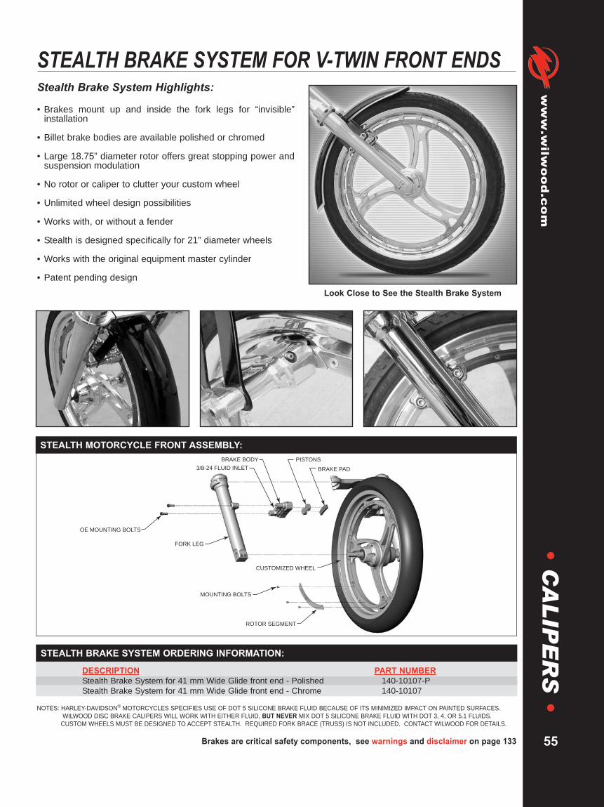
Brakes are critical safety components, see warnings and disclaimer on page 133
www.wilw
ood.com
55
•C
AL
IPE
RS
•
DESCRIPTION PART NUMBERStealth Brake System for 41 mm Wide Glide front end - Polished 140-10107-PStealth Brake System for 41 mm Wide Glide front end - Chrome 140-10107
STEALTH BRAKE SYSTEM ORDERING INFORMATION:
NOTES: HARLEY-DAVIDSON® MOTORCYCLES SPECIFIES USE OF DOT 5 SILICONE BRAKE FLUID BECAUSE OF ITS MINIMIZED IMPACT ON PAINTED SURFACES.WILWOOD DISC BRAKE CALIPERS WILL WORK WITH EITHER FLUID, BUT NEVER MIX DOT 5 SILICONE BRAKE FLUID WITH DOT 3, 4, OR 5.1 FLUIDS.CUSTOM WHEELS MUST BE DESIGNED TO ACCEPT STEALTH. REQUIRED FORK BRACE (TRUSS) IS NOT INCLUDED. CONTACT WILWOOD FOR DETAILS.
Stealth Brake System Highlights:
• Brakes mount up and inside the fork legs for “invisible”installation
• Billet brake bodies are available polished or chromed
• Large 18.75” diameter rotor offers great stopping power andsuspension modulation
• No rotor or caliper to clutter your custom wheel
• Unlimited wheel design possibilities
• Works with, or without a fender
• Stealth is designed specifically for 21” diameter wheels
• Works with the original equipment master cylinder
• Patent pending designLook Close to See the Stealth Brake System
STEALTH BRAKE SYSTEM FOR V-TWIN FRONT ENDS
FORK LEG
CUSTOMIZED WHEEL
OE MOUNTING BOLTS
MOUNTING BOLTS
ROTOR SEGMENT
BRAKE PAD
PISTONSBRAKE BODY
3/8-24 FLUID INLET
STEALTH MOTORCYCLE FRONT ASSEMBLY:

WARNING: The user or installer of any product from this catalog must determine its suitability for their intended purpose or application
www.wilwood.com
56
•B
RA
KE
PA
DS
•BRAKE PADS
PAD COMPOUND QUICK REFERENCE GUIDE:
Wilwood brake pad compounds are the results of three decades of experience and continualdevelopment to provide optimized braking and driver feel for all types of motor sport andcompetition applications. This selection guide is intended to provide general characteristics andapplications for each compound. The graphs on page 58 illustrate the differences in frictionvalues and temperature ranges. On-track testing and driver evaluation however, will alwaysremain the determining factor to final pad selection.
AHeat Range: Low to X-HighCold Torque: X-HighHot Torque: X-HighWear Rate: X-Low
• Immediate cold response with highest friction values at all temperatures• Severe duty use on oval tracks and road courses or other applications thatrequire immediate high response at low temperatures• Long wear rate for severe duty, sustained high temperature braking• Compatible with all iron ,steel, and titanium rotors
HHeat Range: Low to X-HighCold Torque: HighHot Torque: X-HighWear Rate: X-Low
• Slightly softer initial response with same high temperature friction as "A"with a steady rise in friction as temperature and pedal pressure increases• Severe duty use with long wear for oval tracks and road courses• Predictable smooth engagement at all temperatures and pedal pressures• Compatible with all iron, steel, and titanium rotors
BHeat Range: Medium to X-HighCold Torque: Medium-HighHot Torque: HighWear Rate: Low
• Baseline pad for asphalt late models, modifieds, and sprints• Severe duty, high temperature dirt track applications• Intermediate duty road racing, autocross, and rally• Easily bedded without abrasion on new iron or steel rotors• Compatible with all iron, steel, and titanium rotors
CHeat Range: Medium to X-HighCold Torque: MediumHot Torque: Medium-HighWear Rate: X-Low
• Gradual rise from medium to medium high torque as temperatures increase• Long wear and high temperature fade resistance• Tuning pad for reduced response in medium to high temperature ranges• Reduced friction alternative to B• Compatible with all iron, steel, and titanium rotors
CMHeat Range: Medium to HighCold Torque: MediumHot Torque: MediumWear Rate: Medium
• Medium to high friction sintered metallic compound with steadily increasingtorque curve as temperatures rise• Good wear and friction properties with high fade resistance for specialapplications where intermittent high temperature spikes are observedbetween periods of moderate temperature braking• Best compound for specialized application titanium rotors
Compound Performance Range Data General Characteristics and Popular Applications
EHeat Range: Low to Med-HighCold Torque: Medium-HighHot Torque: Medium-HighWear Rate: Medium
• Very consistent positive driver's feel over full temperature range• Baseline material for all dirt track application including super late models,modifieds, and rear inboard sprints using vented iron rotors• Standard equipment in all steel rotor drag race brake kits• Dual purpose street and track rally, auto-cross, and track day events

Brakes are critical safety components, see warnings and disclaimer on page 133
www.wilw
ood.com
57
•B
RA
KE
PA
DS
•
BP-10Heat Range: Low to Med-HighCold Torque: MediumHot Torque: Medium-HighWear Rate: Medium
• Heavy duty replacement pads with increased friction and temperature rangeover OE type compound pads• Standard equipment in many street performance disc conversion kits• Beds quickly and provides fast response without excessive abrasion onvented iron rotors
BP-20Heat Range: Medium-HighCold Torque: MediumHot Torque: HighWear Rate: Medium
• Medium to heavy braking dirt tracks• Advanced level track day and club sport competition• Extreme duty dual purpose street / track vehicle• High speed or heavy weight drag cars• Hobby or sportsman category asphalt racing
BP-30Heat Range: Medium to X-HighCold Torque: Medium-HighHot Torque: HighWear Rate: Low
• Baseline pad for asphalt late models, modifieds, and sprints• Severe duty, high temperature dirt track applications• Intermediate duty road racing, autocross, and rally• Easily bedded without abrasion on new iron or steel rotors• Compatible with all iron, steel, and titanium rotors
QHeat Range: Low to MediumCold Torque: MediumHot Torque: MediumWear Rate: Low
• Disc brake conversions on street rods, muscle cars, custom show cars andall moderate performance applications where low noise and dust areimportant• Best compound for specialized application aluminum rotors, and compatiblewith all vented iron rotors
PMHeat Range: Low to MediumCold Torque: MediumHot Torque: MediumWear Rate: Medium
• Speciality selected compounds for enhanced performance through increased frictionproperties and extended temperature range• Applicaton specific compounds are elements of Wilwood ProMatrix pad & rotor upgrade kits• Where available, ProMatrix compounds are designated for use in OE calipers on OEor performance upgraded rotors, please see our Kit Catalog for details
Compound Performance Range Data General Characteristics and Popular Applications
Bedding is a "real conditions" heat cycle and the final step in preparing the pads for service. All pads, even OE stock replacement parts,will benefit from a proper bedding cycle. Bedding can be done either in the vehicle, or on a special bedding dyno that can realisticallyduplicate the torque loads, pressure, and temperature that will be realized in the vehicle.
The bedding process is the final "heat cure" for the pads. This final bedding cure differs from an oven heat cure in such that the ovenheat cure does not include the pressure, torque, and elevated surface temperatures that are necessary to properly condition the padfor service. New pads must be gradually brought up to temperature and then slowly cooled. If the pads are put into hard service rightfrom the start, damage from fractures or accelerated deterioration due to extreme temperature variations between the surface and thebody of the pad can occur.
Once the brake system has been tested and determined safe to operate the vehicle, follow these steps for bedding of all pad materials.
1. Begin with a series of 8-10 light stops from approx. 30 MPH down to 15 MPH allowing 20-30 seconds for cooling between each stop.2. Progress to series of 8-10 moderate stops from around 45 MPH down to 30 MPH allowing a 20-30 second cool down period
between each stop.3. Proceed with a series of 8-10 hard stops from 55-65 MPH down to 25 MPH allowing 20-30 seconds of cool down time between
each stop.4. Drive at a moderate cruising speed, with the least amount of brake contact possible, until most of the heat has dissipated from the
brakes. Avoid sitting stopped with the brake pedal depressed to hold the car in place during this time. Park the vehicle and allowthe brakes to cool to ambient air temperature.
During the bedding process, a more positive feel from the brakes should develop. This is an indication that the bed in process isworking. If any level of brake fade is observed during the hard stops, it may be an indication that the brakes have been more thanadequately heated. Begin cooling the brakes with light driving and without brake contact immediately.
Wilwood Dyno Bedding Service: Wilwood offers computer controlled dyno bedding on many popular pads and rotors used in hightemperature racing applications. Contact a dealer or factory representative for details.
BRAKE PAD BEDDING:

WARNING: The user or installer of any product from this catalog must determine its suitability for their intended purpose or application
www.wilwood.com
58
•B
RA
KE
PA
DS
•BRAKE PADS
FRICTION VALUES AND TEMPERATURE RANGES:
The graphs below illustrate the differences in friction values and temperature operating ranges for each padcompound. The graphs separate the compounds by similar operating temperature ranges. Pads in the hightemperature group are normally used for sustained high temperature environments as observed on asphalt ovaltracks, road courses, and endurance style competition. Pads from this group can be applied to applications that seeshort duration, but extreme high temperature spikes. Pads in the low to medium temperature group are often foundon most any dirt track applications, drag cars, and high performance disc brake conversions on dual purposestreet/track vehicles. Ultimately, the optimum pad compound for any given application and driver's preference canonly be found after actual on-track testing and evaluation. First, use the performance characteristics and popularapplication guidelines on the preceding page to establish a baseline. Then, use the comparison charts below to makespecific determinations regarding possible adjustments to your combination.
Compound types and ordering information for the pads used in Wilwood calipers can be found within the individualcaliper pages. The pages that follow can also be used to identify and cross-reference the pad shapes and compoundsused in all Wilwood calipers. Other compounds for a few specialized applications are also listed. A complete list ofthe Wilwood pads and compounds that are available for many OE calipers as well as other brands of racing caliperscan be found in the Wilwood High Performance Disc Brake Pad catalog.
0 100 200 300 400 500 600 700 800 900 1,000 1,100 1,200 1,300Temperature (°F)
LEGEND:Compound “BP-30”
Compound "A"
Compound "H"
Compound "J"
Compound "B"
Compound "C"
.70
.60
.50
.40
.30
.20
Cf
.70
.60
.50
.40
.30
.200 100 200 300 400 500 600 700 800 900 1,000 1,100 1,200 1,300
Temperature (°F)
Cf
LEGEND:
Compound "BP-10"
Compound "BP-20"
Compound "E"
Compound "Q"

Brakes are critical safety components, see warnings and disclaimer on page 133
www.wilw
ood.com
59
•B
RA
KE
PA
DS
•.30
(7,6)
2.74 (69,6)
1.66 (42,2)
.30
(7,6)AXLE SET P/N PAD TYPE / COMPOUND150 - 8733-2 6208 10 BP-10 Smart Pad
GP 300 / 310 BRAKE PAD TYPE 6208:
.44
(11,2)
2.74 (69,6)
1.66 (42,2)
.44
(11,2)
AXLE SET P/N PAD TYPE / COMPOUND15H - 8596K 6211 H PolyMatrix150 - 10396K 6211 CM For Titanium Rotor
GP 320 BRAKE PAD TYPE 6211:
2.74 (69,6)
6.40 (162,6) .71
(18,0)
AXLE SET P/N PAD TYPE / COMPOUND15Q- 8823K 6318 Q PolyMatrix150 - 9118K 6318 10 BP-10 Smart Pad150 - 9411K 6318 20 BP-20 Smart Pad
TC 6R TRUCK BRAKE PAD TYPE 6318:
.67
(17,0)
2.87 (72,9)
5.87 (149,1)AXLE SET P/N PAD TYPE / COMPOUND15A - 9977K 6617 A PolyMatrix15B - 9978K 6617 B PolyMatrix15H - 9979K 6617 H PolyMatrix150 - 9488K 6617 10 BP-10 Smart Pad150 - 9489K 6617 20 BP-20 Smart Pad150 - 9980K 6617 30 BP-30 Smart Pad
W4A / W6A BRAKE PAD TYPE 6617:
2.36 (59,9)
.49(12,4)
4.86 (123,4)AXLE SET P/N PAD TYPE / COMPOUND15A - 10724K 6612 A PolyMatrix15B - 10725K 6612 B PolyMatrix15H - 10726K 6712 H PolyMatrix150 - 10006K 6712 10 BP-10 Smart Pad150 - 10007K 6712 20 BP-20 Smart Pad
DYNAPRO 6 BRAKE PAD TYPE 6712:
.67
(17,0)
9)
5

WARNING: The user or installer of any product from this catalog must determine its suitability for their intended purpose or application
www.wilwood.com
60
•B
RA
KE
PA
DS
•BRAKE PADS
2.38 (60,5)
.49
(12,4)
3.96 (100,6) .49
(12,4)
3
AXLE SET P/N PAD TYPE / COMPOUND15A - 5734K 7112 A PolyMatrix15B - 3991K 7112 B PolyMatrix15C - 4415K 7112 C PolyMatrix15E - 6096K 7112 E PolyMatrix15H - 8291K 7112 H PolyMatrix15Q- 6824K 7112 Q PolyMatrix150 - 8850K 7112 10 BP-10 Smart Pad150 - 9413K 7112 20 BP-20 Smart Pad150 - 9863K 7112 30 BP-30 Smart Pad150 - 8450K 7112 CM For Titanium Rotor
DYNALITE BRAKE PAD TYPE 7112:
2.32 (58,9)
.50(12,7)
1.98 (50,3) .50(12,7)
AXLE SET P/N PAD TYPE / COMPOUND15A - 5733K 7012 A PolyMatrix15B - 3990K 7012 B PolyMatrix15C - 4414K 7012 C PolyMatrix15E - 6083K 7012 E PolyMatrix15Q- 6823K 7012 Q PolyMatrix150 - 8937K 7012 10 BP-10 Smart Pad150 - 9412K 7012 20 BP-20 Smart Pad150 - 9862K 7012 30 BP-30 Smart Pad150 - 9756K 7012 CM For Titanium Rotor150 - 9683K 7012 Purple
DYNALITE SINGLE BRAKE PAD TYPE 7012:
2.32 (58,9)
.50(12,7)
1.98 (50,3) AXLE SET P/N PAD TYPE / COMPOUND15A - 10142K 6812 A PolyMatrix15B - 9819K 6812 B PolyMatrix15E - 9820K 6812 E PolyMatrix15Q- 10144K 6812 Q PolyMatrix150 - 9764K 6812 10 BP-10 Smart Pad150 - 9765K 6812 20 BP-20 Smart Pad150 - 9862K 6812 30 BP-30 Smart Pad150 - 9756K 6812 CM For Titanium Rotor150 - 9766K 6812 Purple
DYNAPRO SINGLE BRAKE PAD TYPE 6812:
.50(12,7)
1.94 (49,3)
.63
(16,0)
4.00 (101,6) AXLE SET P/N PAD TYPE / COMPOUND150 - 9904K 6916 CM For Titanium Rotor
ULTRALITE BRAKE PAD TYPE 6916:
.63
(16,0)
4
NOTE: THIS PAD SHAPE CAN BE USED IN WILWOOD CALIPERS DESIGNED FORTYPE 7012 PADS
NOTE: PAD TYPE 6812 CAN BE USED AS A REPLACEMENT FOR PAD TYPE 7012

Brakes are critical safety components, see warnings and disclaimer on page 133
www.wilw
ood.com
61
•B
RA
KE
PA
DS
•
2.30 (58,4)
.49
(12,4)
3.96 (100,6)
)
.49
(12,4)
3 AXLE SET P/N PAD TYPE / COMPOUND15A - 5909K 7212 A PolyMatrix15B - 3999K 7212 B PolyMatrix15E - 6098K 7212 E PolyMatrix15Q- 6825K 7212 Q PolyMatrix150 - 8857K 7212 10 BP-10 Smart Pad150 - 8451K 7212 CM For Titanium Rotor
BILLET DYNALITE BRAKE PAD TYPE 7212:
2.30 (58,4)
.63
(16,0)
3.96 (100,6)
)
.63
(16,0)
3AXLE SET P/N PAD TYPE / COMPOUND15A - 5769K 7216 A PolyMatrix15B - 4410K 7216 B PolyMatrix15C - 4959K 7216 C PolyMatrix15E - 6099K 7216 E PolyMatrix15H - 8290K 7216 H PolyMatrix15Q- 6826K 7216 Q PolyMatrix150 - 8858K 7216 10 BP-10 Smart Pad150 - 9419K 7216 20 BP-20 Smart Pad150 - 7504K 7216 CM For Titanium Rotor
NDL BRAKE PAD TYPE 7216:
2.43 (61,7)
.80
(20,3)
4.74 (120,4)
2.43 (61,7)
.65
(16,5)
4.74 (120,4) AXLE SET P/N PAD TYPE / COMPOUND15A - 6704K 7416 A PolyMatrix15B - 6705K 7416 B PolyMatrix15E - 6707K 7416 E PolyMatrix15H - 8546K 7416 H PolyMatrix15Q- 6828K 7416 Q PolyMatrix150 - 8855K 7416 10 BP-10 Smart Pad150 - 9415K 7416 20 BP-20 Smart Pad
SL6R BRAKE PAD TYPE 7416:
AXLE SET P/N PAD TYPE / COMPOUND15A - 5735K 7320 A PolyMatrix15B - 3992K 7320 B PolyMatrix15C - 4040K 7320 C PolyMatrix15E - 6100K 7320 E PolyMatrix15H - 8108K 7320 H PolyMatrix15Q- 6827K 7320 Q PolyMatrix150 - 8856K 7320 10 BP-10 Smart Pad150 - 9414K 7216 20 BP-20 Smart Pad150 - 8285K 7320 CM For Titanium Rotor150 - 4909K 7320 Rapco
SUPERLITE II, SUPERLITE III, BILLETSUPERLITE W/COTTER PIN BRAKE PAD TYPE 7320:
NOTE: PAD SHAPE 7812 CAN BE USED AS A REPLACEMENT FOR PAD TYPE 7212
NOTE: PAD SHAPE 7816 CAN BE USED AS A REPLACEMENT FOR PAD TYPE 7216

WARNING: The user or installer of any product from this catalog must determine its suitability for their intended purpose or application
www.wilwood.com
62
•B
RA
KE
PA
DS
•BRAKE PADS
2.43 (61,7)
.80
(20,3)
4.74 (120,4) .80
(20,3)
4 AXLE SET P/N PAD TYPE / COMPOUND15A - 5938K 7420 A PolyMatrix15B - 5939K 7420 B PolyMatrix15C - 6853K 7420 C PolyMatrix15E - 6084K 7420 E PolyMatrix15H - 8114K 7420 H PolyMatrix15Q- 6829K 7420 Q PolyMatrix150 - 8854K 7420 10 BP-10 Smart Pad150 - 9416K 7420 20 BP-20 Smart Pad150 - 9864K 7420 30 BP-30 Smart Pad150 - 8323K 7320 CM For Titanium Rotor
SL6R BRAKE PAD TYPE 7420:
1.83 (46,5)
3.93 (99,8) .79
(20,1)
.79
(20,1)AXLE SET P/N PAD TYPE / COMPOUND15A - 5772K 7620 A PolyMatrix15C - 4721K 7620 C PolyMatrix15H - 8112K 7620 H PolyMatrix150 - 4717K 7620 Rapco Pad
(.34”Thick)
IR-GT4R BRAKE PAD TYPE 7620:
2.53 (64,3)
5.99 (152,1) .80
(20,3)AXLE SET P/N PAD TYPE / COMPOUND15A - 5736K 7520 A PolyMatrix15B - 3993K 7520 B PolyMatrix15E - 6101K 7520 E PolyMatrix15Q- 6879K 7520 Q PolyMatrix150 - 9425K 7520 10 BP-10 Smart Pad150 - 9417K 7520 20 BP-20 Smart Pad
GN III BRAKE PAD TYPE 7520:
2.21 (56,0)
.49
(12,4)
3.96 (100,6) AXLE SET P/N PAD TYPE / COMPOUND15A - 9835K 7812 A PolyMatrix15B - 9836K 7812 B PolyMatrix15E - 9837K 7812 E PolyMatrix15H - 10644K 7812 H PolyMatrix15Q- 10385K 7812 Q PolyMatrix150 - 9136K 7812 10 BP-10 Smart Pad150 - 9418K 7812 20 BP-20 Smart Pad150 - 10020K 7812 CMFor Titanium Rotor
DYNAPRO BRAKE PAD TYPE 7812:
.49
(12,4)
3
NOTE:THIS PAD SHAPE CAN BE USED IN WILWOOD CALIPERS DESIGNED FOR TYPE 7212 PADS
2.53 (64,3)
5.99 (152,1) .65
(16,5)
AXLE SET P/N PAD TYPE / COMPOUND15A - 10648K 7516 A PolyMatrix15E - 10228K 7516 E PolyMatrix150 - 9605K 7516 20 BP-20 Smart Pad
GN III BRAKE PAD TYPE 7516:

Brakes are critical safety components, see warnings and disclaimer on page 133
www.wilw
ood.com
63
•B
RA
KE
PA
DS
•
2.31 (58,6)
3.13 (79,5) .49
(12,4)
.49
(12,4)
AXLE SET P/N PAD TYPE / COMPOUND15A - 8809K 7912 A PolyMatrix15B - 8949K 7912 B PolyMatrix15E - 8810K 7912 E PolyMatrix15H - 8811K 7912 H PolyMatrix15Q- 8812K 7912 Q PolyMatrix150 - 8813K 7912 10 BP-10 Smart Pad150 - 9420K 7912 20 BP-20 Smart Pad
POWERLITE BRAKE PAD TYPE 7912:
2.21 (56,0)
.60
(15,2)
3.96 (100,6)
6,0)
.60
(15,2)
3 AXLE SET P/N PAD TYPE / COMPOUND15A - 7263K 7816 A PolyMatrix15B - 7264K 7816 B PolyMatrix15E - 7266K 7816 E PolyMatrix15H - 10645K 7816 H PolyMatrix15Q- 7268K 7816 Q PolyMatrix150 - 8946K 7816 10 BP-10 Smart Pad150 - 9419K 7816 20 BP-20 Smart Pad150 - 9865K 7816 30 BP-30 Smart Pad150 - 9753K 7816 CM For Titanium Rotor150 - 10290K 7816 CM Modified
DYNAPRO AND NDL BRAKE PAD TYPE 7816:
2.77
(70,4)
5.98 (151,9) 1.18
(30,0)
1.18
(30,0)
AXLE SET P/N PAD TYPE / COMPOUND15A - 7509K 9330 A PolyMatrix15H - 8119K 9330 H PolyMatrix
STR BRAKE PAD TYPE 9330:
1.10
(27,9)
2.88 (73,2)
5.13 (130,3) 1.10
(27,9)
3,2)
5
AXLE SET P/N PAD TYPE / COMPOUND15A - 5739K 9428 A PolyMatrix
GT III/ST, GT III, GT 6000 BRAKE PAD TYPE 9428:
2.88 (73,2)
5.13 (130,3) 1.10
(27,9)
3,2)
5 1.10
(27,9)
AXLE SET P/N PAD TYPE / COMPOUND15A - 6225K 9528 A PolyMatrix15H - 8125K 9528 H PolyMatrix
GT III/ST, GT III, GT 6000 SPECIAL RADIUS BRAKE PAD TYPE 9528:
NOTE: THIS PAD SHAPE CAN BE USED IN WILWOOD CALIPERS DESIGNED FORTYPE 7216 PADS
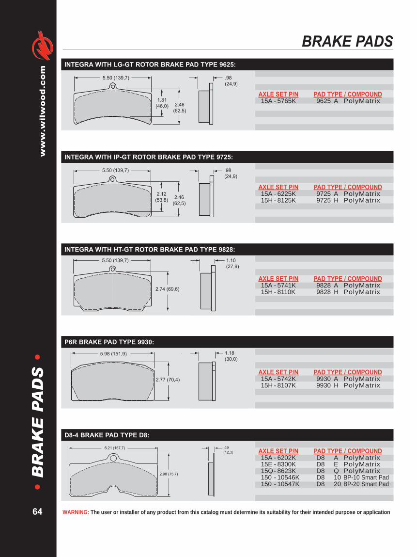
WARNING: The user or installer of any product from this catalog must determine its suitability for their intended purpose or application
www.wilwood.com
64
•B
RA
KE
PA
DS
•BRAKE PADS
.98
(24,9)
2.46
(62,5)
5.50 (139,7)
1.81
(46,0)
AXLE SET P/N PAD TYPE / COMPOUND15A - 5765K 9625 A PolyMatrix
INTEGRA WITH LG-GT ROTOR BRAKE PAD TYPE 9625:
.98
(24,9)
2.46
(62,5)
2.12
(53,8)
5.50 (139,7)
AXLE SET P/N PAD TYPE / COMPOUND15A - 6225K 9725 A PolyMatrix15H - 8125K 9725 H PolyMatrix
INTEGRA WITH IP-GT ROTOR BRAKE PAD TYPE 9725:
1.10
(27,9)
2.74 (69,6)
5.50 (139,7) 1.10
(27,9)
2
AXLE SET P/N PAD TYPE / COMPOUND15A - 5741K 9828 A PolyMatrix15H - 8110K 9828 H PolyMatrix
INTEGRA WITH HT-GT ROTOR BRAKE PAD TYPE 9828:
2.77 (70,4)
5.98 (151,9) 1.18
(30,0)
1.18
(30,0)
AXLE SET P/N PAD TYPE / COMPOUND15A - 5742K 9930 A PolyMatrix15H - 8107K 9930 H PolyMatrix
P6R BRAKE PAD TYPE 9930:
2.98 (75,7)
.49
(12,3)6.21 (157,7) AXLE SET P/N PAD TYPE / COMPOUND
15A - 6202K D8 A PolyMatrix15E - 8300K D8 E PolyMatrix15Q- 8623K D8 Q PolyMatrix150 - 10546K D8 10 BP-10 Smart Pad150 - 10547K D8 20 BP-20 Smart Pad
D8-4 BRAKE PAD TYPE D8:
.49
(12,3)6

Brakes are critical safety components, see warnings and disclaimer on page 133
www.wilw
ood.com
65
•B
RA
KE
PA
DS
•
GM "INNER" PAD
2.08
(52,8)
.58
(14,7)
5.35 (135,9)
GM "OUTER" PAD
2.41
(61,2)
.52
(13,2)
7.77 (197,4)
AXLE SET P/N PAD TYPE / COMPOUND15A - 5737K D52 A PolyMatrix15B - 3994K D52 B PolyMatrix15C - 4419K D52 C PolyMatrix15E - 6102K D52 E PolyMatrix15H - 8232K D52 H PolyMatrix15Q- 6830K D52 Q PolyMatrix150 - 8939K D52 10 BP-10 Smart Pad150 - 9421K D52 20 BP-20 Smart Pad150 - 9866K D52 30 BP-30 Smart Pad
GM III BRAKE PAD TYPE D52:
.67 (17,0)
.52
(13,2)4.96 (126,0)
GM "INNER" PAD
.52
(13,2)
4.89 (124,2)
2.56
(65,0)
GM “OUTER” PAD
GM “OUTER” PAD
AXLE SET P/N PAD TYPE / COMPOUND15A - 6219K D154 A PolyMatrix15B - 3998K D154 B PolyMatrix15C - 4420K D154 C PolyMatrix15E - 6103K D154 E PolyMatrix15Q- 6831K D154 Q PolyMatrix150 - 8936K D154 10 BP-10 Smart Pad150 - 9422K D154 20 BP-20 Smart Pad
GM METRIC BRAKE PAD TYPE D154:
.58
(14,7)
3.43 (87,1)
2.08 (52,8)
AXLE SET P/N PAD TYPE / COMPOUND15Q- 10254K D340 Q PolyMatrix150 - 9184K D340 10 BP-10 Smart Pad150 - 10661K D340 20 BP-20 Smart Pad
COMBINATION PARKING BRAKE (CPB) CALIPER BRAKE PAD TYPE D340:
.58
(14,7)
3

WARNING: The user or installer of any product from this catalog must determine its suitability for their intended purpose or application
www.wilwood.com
66
•R
OT
OR
S•
ROTOR INFORMATIONRotor Performance:Wilwood Engineering produces over 120 different types of premiumrotors designed specifically for racing and high performanceapplications. Although a rotor’s basic function is to disburse energy (inthe form of heat) created by the brake pads clamping onto the rapidlyrotating rotor, how well a rotor performs this job under the extremes ofracing is why Wilwood rotors are considered the best in the industry.
The key elements involved in a high performance rotor are:•What is the mechanical advantage of the rotor (diameter)?
•How stable (resistant to cracking) is the rotor material duringthermal cycling (the continual process of heating and cooling)?
•How stable is the rotor material when thermal shock occurs (thelarge, sudden, rapid change in rotor temperature)?
•How efficient the rotor is at disbursing heat caused by frictionbetween the rotor and brake pad?
•How light the rotor can be made and still perform the task required(rotating weight not only contributes to unwanted unsprung weight,but also rotating weight)?
Wilwood Engineers address these and other critical questions when designingrotors. Because race cars differ in their braking requirements, Wilwood hasdeveloped both specific designs and specialized materials and manufacturingtechniques to accommodate different performance criteria.
Wilwood vented rotors are designed for maximum cooling. The internal vanespump cool air from the center of the wheel and take heat away from the rotor,allowing rotor temperatures to decrease. Wilwood has designed specialcurved vane and straight vane rotors to effectively move large volumes of airto rapidly disburse this heat (energy). Specially formulated iron is used toenhance the stability of the rotor, while allowing difficult castings in complexvane configurations to be produced. Wilwood’s proprietary casting techniquesare the result of over 30 years of vented rotor research and developmentcombined with actual on-track performance evaluation. All rotors are precisionmachined to assure surfaces are flat and parallel.
Wilwood specialty steel rotors are used when rapid thermal inputs occurand material stability is required (i.e. when a dragster must brake from 300mph). Under such conditions specialty steels are used, often cross drilledto reduce rotational weight. Wilwood also manufactures dynamic mountrotors for Super Speedway applications as well as special limited dutystreet rod and pro series solid rotors.
For all rotor designs, Wilwood conducts extensive in-house dynamometertesting to measure results of rotors under the most demanding conditions.This unique testing, teamed with extensive research and development andtrack testing assure the racer of the best quality high performance rotorsavailable.
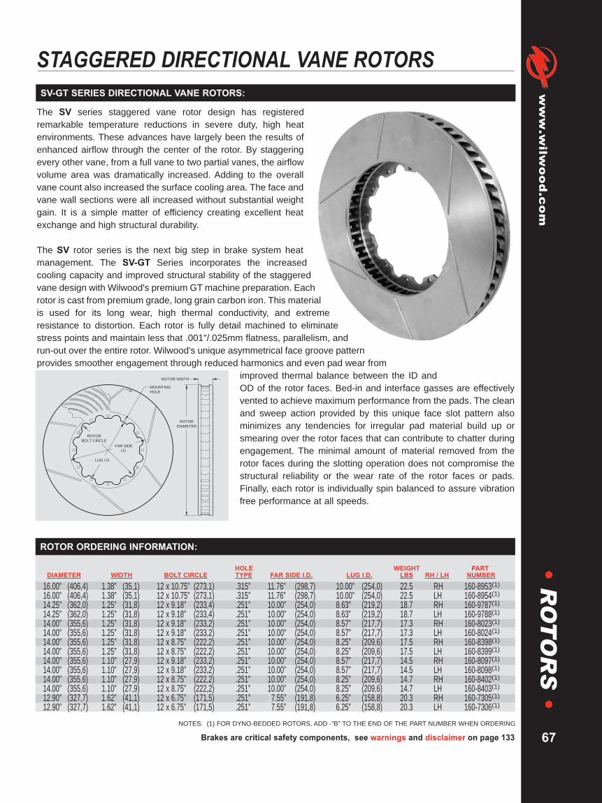
Brakes are critical safety components, see warnings and disclaimer on page 133
www.wilw
ood.com
67
•R
OT
OR
S•
STAGGERED DIRECTIONAL VANE ROTORS
HOLE WEIGHT PARTDIAMETER WIDTH BOLT CIRCLE TYPE FAR SIDE I.D. LUG I.D. LBS RH / LH NUMBER
16.00” (406,4) 1.38” (35,1) 12 x 10.75” (273,1) .315” 11.76” (298,7) 10.00” (254,0) 22.5 RH 160-8953(1)16.00” (406,4) 1.38” (35,1) 12 x 10.75” (273,1) .315” 11.76” (298,7) 10.00” (254,0) 22.5 LH 160-8954(1)14.25” (362,0) 1.25” (31,8) 12 x 9.18” (233,4) .251” 10.00” (254,0) 8.63” (219,2) 18.7 RH 160-9787(1)14.25” (362,0) 1.25” (31,8) 12 x 9.18” (233,4) .251” 10.00” (254,0) 8.63” (219,2) 18.7 LH 160-9788(1)14.00” (355,6) 1.25” (31,8) 12 x 9.18” (233,2) .251” 10.00” (254,0) 8.57” (217,7) 17.3 RH 160-8023(1)14.00” (355,6) 1.25” (31,8) 12 x 9.18” (233,2) .251” 10.00” (254,0) 8.57” (217,7) 17.3 LH 160-8024(1)14.00” (355,6) 1.25” (31,8) 12 x 8.75” (222,2) .251” 10.00” (254,0) 8.25” (209,6) 17.5 RH 160-8398(1)14.00” (355,6) 1.25” (31,8) 12 x 8.75” (222,2) .251” 10.00” (254,0) 8.25” (209,6) 17.5 LH 160-8399(1)14.00” (355,6) 1.10” (27,9) 12 x 9.18” (233,2) .251” 10.00” (254,0) 8.57” (217,7) 14.5 RH 160-8097(1)14.00” (355,6) 1.10” (27,9) 12 x 9.18” (233,2) .251” 10.00” (254,0) 8.57” (217,7) 14.5 LH 160-8098(1)14.00” (355,6) 1.10” (27,9) 12 x 8.75” (222,2) .251” 10.00” (254,0) 8.25” (209,6) 14.7 RH 160-8402(1)14.00” (355,6) 1.10” (27,9) 12 x 8.75” (222,2) .251” 10.00” (254,0) 8.25” (209,6) 14.7 LH 160-8403(1)12.90” (327,7) 1.62” (41,1) 12 x 6.75” (171,5) .251” 17.55” (191,8) 6.25” (158,8) 20.3 RH 160-7305(1)12.90” (327,7) 1.62” (41,1) 12 x 6.75” (171,5) .251” 17.55” (191,8) 6.25” (158,8) 20.3 LH 160-7306(1)
ROTOR ORDERING INFORMATION:
NOTES: (1) FOR DYNO-BEDDED ROTORS, ADD -”B” TO THE END OF THE PART NUMBER WHEN ORDERING
The SV series staggered vane rotor design has registeredremarkable temperature reductions in severe duty, high heatenvironments. These advances have largely been the results ofenhanced airflow through the center of the rotor. By staggeringevery other vane, from a full vane to two partial vanes, the airflowvolume area was dramatically increased. Adding to the overallvane count also increased the surface cooling area. The face andvane wall sections were all increased without substantial weightgain. It is a simple matter of efficiency creating excellent heatexchange and high structural durability.
The SV rotor series is the next big step in brake system heatmanagement. The SV-GT Series incorporates the increasedcooling capacity and improved structural stability of the staggeredvane design with Wilwood's premium GTmachine preparation. Eachrotor is cast from premium grade, long grain carbon iron. This materialis used for its long wear, high thermal conductivity, and extremeresistance to distortion. Each rotor is fully detail machined to eliminatestress points and maintain less that .001"/.025mm flatness, parallelism, andrun-out over the entire rotor. Wilwood's unique asymmetrical face groove patternprovides smoother engagement through reduced harmonics and even pad wear from
improved thermal balance between the ID andOD of the rotor faces. Bed-in and interface gasses are effectivelyvented to achieve maximum performance from the pads. The cleanand sweep action provided by this unique face slot pattern alsominimizes any tendencies for irregular pad material build up orsmearing over the rotor faces that can contribute to chatter duringengagement. The minimal amount of material removed from therotor faces during the slotting operation does not compromise thestructural reliability or the wear rate of the rotor faces or pads.Finally, each rotor is individually spin balanced to assure vibrationfree performance at all speeds.
ROTOR
DIAMETER
ROTOR WIDTH
MOUNTING
HOLE
ROTOR
BOLT CIRCLE
LUG I.D.
FAR SIDE
I.D.
SV-GT SERIES DIRECTIONAL VANE ROTORS:

WARNING: The user or installer of any product from this catalog must determine its suitability for their intended purpose or application
www.wilwood.com
68
•R
OT
OR
S•
DIRECTIONAL VANE ROTORS
HOLE WEIGHT PARTDIAMETER WIDTH BOLT CIRCLE TYPE FAR SIDE I.D. LUG I.D. LBS RH / LH NUMBER
14.00” (355,6) 1.25” (31,8) 12 x 8.75” (222,3) .251” 10.00” (254,0) 8.25” (209,6) 17.5 RH 160-8398(1)
14.00” (355,6) 1.25” (31,8) 12 x 8.75” (222,3) .251” 10.00” (254,0) 8.25” (209,6) 17.5 LH 160-8399(1)
14.00” (355,6) 1.10” (27,9) 12 x 8.75” (222,3) .251” 10.00” (254,0) 8.25” (209,6) 14.7 RH 160-8402(1)
14.00” (355,6) 1.10” (27,9) 12 x 8.75” (222,3) .251” 10.00” (254,0) 8.25” (209,6) 14.7 LH 160-8403(1)
13.06” (331,7) 1.38” (35,0) 8 x 7.00” (177,8) .313” 9.21” (233,9) 6.53” (165,9) 16.0 RH 160-3584(1)
13.06” (331,7) 1.38” (35,0) 8 x 7.00” (177,8) .313” 9.21” (233,9) 6.53” (165,9) 16.0 LH 160-3585(1)
13.06” (331,7) 1.25” (31,8) 12 x 8.75” (222,3) .251” 9.46” (240,3) 8.25” (209,6) 12.3 RH 160-8165(1)
13.06” (331,7) 1.25” (31,8) 12 x 8.75” (222,3) .251” 9.46” (240,3) 8.25” (209,6) 12.3 LH 160-8166(1)
13.00” (330,2) 1.10” (27,9) 12 x 7.00” (177,8) .251” 8.57” (217,7) 6.38” (162,0) 14.6 RH 160-8508(1)
13.00” (330,2) 1.10” (27,9) 12 x 7.00” (177,8) .251” 8.57” (217,7) 6.38” (162,0) 14.6 LH 160-8509(1)
12.91” (328,0) 1.38” (35,0) 12 x 7.17” (182,0) 8 mm 7.86” (199,7) 6.25” (158,8) 19.3 RH 160-6843(1)
12.91” (328,0) 1.38” (35,0) 12 x 7.17” (182,0) 8 mm 7.86” (199,7) 6.25” (158,8) 19.3 LH 160-6844(1)
12.91” (328,0) 1.26” (32,0) 10 x 8.11” (206,0) 8 mm 8.66” (220,0) 7.24” (184,0) 14.3 RH 160-7137(1)
12.91” (328,0) 1.26” (32,0) 10 x 8.11” (206,0) 8 mm 8.66” (220,0) 7.24” (184,0) 14.3 LH 160-7138(1)
12.90” (327,7) 1.38” (35,0) 12 x 7.00” (177,8) .251” 8.05” (204,5) 6.55” (166,4) 18.6 RH 160-4932(1)
12.90” (327,7) 1.38” (35,0) 12 x 7.00” (177,8) .251” 8.05” (204,5) 6.55” (166,4) 18.6 LH 160-4933(1)
12.90” (327,7) 1.38” (35,0) 12 x 6.75” (171,5) .251” 7.55” (191,8) 6.25” (158,8) 19.4 RH 160-5122(1)
12.90” (327,7) 1.38” (35,0) 12 x 6.75” (171,5) .251” 7.55” (191,8) 6.25” (158,8) 19.4 LH 160-5123(1)
ROTOR ORDERING INFORMATION:
GT-36, GT-40, and GT-48 vane rotors are built for the extremeconditions of professional motorsports. The superior heat absorptionand dissipation characteristics of these heavy wall directional vanerotors are the keys to preventing heat fade and realizing long service lifefrom the rotors and pads. All rotors are cast from premium grade, longgrain carbon iron for long wear, thermal stability, and resistance todistortion. Every GT rotor is fully detail machined to eliminate stresspoints and unnecessary weight away from the pad sweep face. Thefaces and O.D. are precision turned to less than .001" for flatness,
parallelism, and run-out. An asymmetricalface slot patternprovides smootherengagement throughreduced harmonicsand improved thermalbalance between theI.D. and O.D. of therotor. Every rotor isthen individuallydynamic balanced to provide vibration free performance at anyspeed. These rotors provide the highest cooling capacity andlongest service life for extreme braking short tracks and road coursecompetition.
ROTOR
DIAMETER
ROTOR WIDTH
MOUNTING
HOLE
ROTOR
BOLT CIRCLE
LUG I.D.
FAR SIDE
I.D.
12 Bolt Configuration
GT SERIES DIRECTIONAL VANE ROTORS:
NOTES: (1) FOR DYNO-BEDDED ROTORS, ADD -”B” TO THE END OF THE PART NUMBER WHEN ORDERING
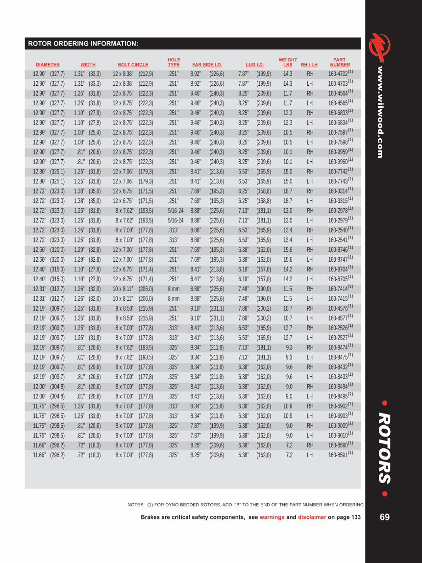
HOLE WEIGHT PARTDIAMETER WIDTH BOLT CIRCLE TYPE FAR SIDE I.D. LUG I.D. LBS RH / LH NUMBER
12.90” (327,7) 1.31” (33,3) 12 x 8.38” (212,9) .251” 8.92” (226,6) 7.87” (199,9) 14.3 RH 160-4702(1)
12.90” (327,7) 1.31” (33,3) 12 x 8.38” (212,9) .251” 8.92” (226,6) 7.87” (199,9) 14.3 LH 160-4703(1)
12.90” (327,7) 1.25” (31,8) 12 x 8.75” (222,3) .251” 9.46” (240,3) 8.25” (209,6) 11.7 RH 160-4564(1)
12.90” (327,7) 1.25” (31,8) 12 x 8.75” (222,3) .251” 9.46” (240,3) 8.25” (209,6) 11.7 LH 160-4565(1)
12.90” (327,7) 1.10” (27,9) 12 x 8.75” (222,3) .251” 9.46” (240,3) 8.25” (209,6) 12.3 RH 160-6833(1)
12.90” (327,7) 1.10” (27,9) 12 x 8.75” (222,3) .251” 9.46” (240,3) 8.25” (209,6) 12.3 LH 160-6834(1)
12.90” (327,7) 1.00” (25,4) 12 x 8.75” (222,3) .251” 9.46” (240,3) 8.25” (209,6) 10.5 RH 160-7597(1)
12.90” (327,7) 1.00” (25,4) 12 x 8.75” (222,3) .251” 9.46” (240,3) 8.25” (209,6) 10.5 LH 160-7598(1)
12.90” (327,7) .81” (20,6) 12 x 8.75” (222,3) .251” 9.46” (240,3) 8.25” (209,6) 10.1 RH 160-9959(1)
12.90” (327,7) .81” (20,6) 12 x 8.75” (222,3) .251” 9.46” (240,3) 8.25” (209,6) 10.1 LH 160-9960(1)
12.80” (325,1) 1.25” (31,8) 12 x 7.06” (179,3) .251” 8.41” (213,6) 6.53” (165,9) 15.0 RH 160-7742(1)
12.80” (325,1) 1.25” (31,8) 12 x 7.06” (179,3) .251” 8.41” (213,6) 6.53” (165,9) 15.0 LH 160-7743(1)
12.72” (323,0) 1.38” (35,0) 12 x 6.75” (171,5) .251” 7.69” (195,3) 6.25” (158,8) 18.7 RH 160-3314(1)
12.72” (323,0) 1.38” (35,0) 12 x 6.75” (171,5) .251” 7.69” (195,3) 6.25” (158,8) 18.7 LH 160-3315(1)
12.72” (323,0) 1.25” (31,8) 8 x 7.62” (193,5) 5/16-24 8.88” (225,6) 7.13” (181,1) 13.0 RH 160-2978(1)
12.72” (323,0) 1.25” (31,8) 8 x 7.62” (193,5) 5/16-24 8.88” (225,6) 7.13” (181,1) 13.0 LH 160-2979(1)
12.72” (323,0) 1.25” (31,8) 8 x 7.00” (177,8) .313” 8.88” (225,6) 6.53” (165,9) 13.4 RH 160-2540(1)
12.72” (323,0) 1.25” (31,8) 8 x 7.00” (177,8) .313” 8.88” (225,6) 6.53” (165,9) 13.4 LH 160-2541(1)
12.60” (320,0) 1.29” (32,8) 12 x 7.00” (177,8) .251” 7.69” (195,3) 6.38” (162,0) 15.6 RH 160-8746(1)
12.60” (320,0) 1.29” (32,8) 12 x 7.00” (177,8) .251” 7.69” (195,3) 6.38” (162,0) 15.6 LH 160-8747(1)
12.40” (315,0) 1.10” (27,9) 12 x 6.75” (171,4) .251” 8.41” (213,6) 6.18” (157,0) 14.2 RH 160-8704(1)
12.40” (315,0) 1.10” (27,9) 12 x 6.75” (171,4) .251” 8.41” (213,6) 6.18” (157,0) 14.2 LH 160-8705(1)
12.31” (312,7) 1.26” (32,0) 10 x 8.11” (206,0) 8 mm 8.88” (225,6) 7.48” (190,0) 11.5 RH 160-7414(1)
12.31” (312,7) 1.26” (32,0) 10 x 8.11” (206,0) 8 mm 8.88” (225,6) 7.48” (190,0) 11.5 LH 160-7415(1)
12.19” (309,7) 1.25” (31,8) 8 x 8.50” (215,9) .251” 9.10” (231,1) 7.88” (200,2) 10.7 RH 160-4576(1)
12.19” (309,7) 1.25” (31,8) 8 x 8.50” (215,9) .251” 9.10” (231,1) 7.88” (200,2) 10.7 LH 160-4577(1)
12.19” (309,7) 1.25” (31,8) 8 x 7.00” (177,8) .313” 8.41” (213,6) 6.53” (165,9) 12.7 RH 160-2526(1)
12.19” (309,7) 1.25” (31,8) 8 x 7.00” (177,8) .313” 8.41” (213,6) 6.53” (165,9) 12.7 LH 160-2527(1)
12.19” (309,7) .81” (20,6) 8 x 7.62” (193,5) .325” 8.34” (211,8) 7.13” (181,1) 9.3 RH 160-8474(1)
12.19” (309,7) .81” (20,6) 8 x 7.62” (193,5) .325” 8.34” (211,8) 7.13” (181,1) 19.3 LH 160-8475(1)
12.19” (309,7) .81” (20,6) 8 x 7.00” (177,8) .325” 8.34” (211,8) 6.38” (162,0) 9.6 RH 160-8432(1)
12.19” (309,7) .81” (20,6) 8 x 7.00” (177,8) .325” 8.34” (211,8) 6.38” (162,0) 9.6 LH 160-8433(1)
12.00” (304,8) .81” (20,6) 8 x 7.00” (177,8) .325” 8.41” (213,6) 6.38” (162,0) 9.0 RH 160-8494(1)
12.00” (304,8) .81” (20,6) 8 x 7.00” (177,8) .325” 8.41” (213,6) 6.38” (162,0) 19.0 LH 160-8495(1)
11.75” (298,5) 1.25” (31,8) 8 x 7.00” (177,8) .313” 8.34” (211,8) 6.38” (162,0) 10.9 RH 160-6902(1)
11.75” (298,5) 1.25” (31,8) 8 x 7.00” (177,8) .313” 8.34” (211,8) 6.38” (162,0) 10.9 LH 160-6903(1)
11.75” (298,5) .81” (20,6) 8 x 7.00” (177,8) .325” 7.87” (199,9) 6.38” (162,0) 9.0 RH 160-9009(1)
11.75” (298,5) .81” (20,6) 8 x 7.00” (177,8) .325” 7.87” (199,9) 6.38” (162,0) 9.0 LH 160-9010(1)
11.66” (296,2) .72” (18,3) 8 x 7.00” (177,8) .325” 8.25” (209,6) 6.38” (162,0) 7.2 RH 160-8590(1)
11.66” (296,2) .72” (18,3) 8 x 7.00” (177,8) .325” 8.25” (209,6) 6.38” (162,0) 7.2 LH 160-8591(1)
Brakes are critical safety components, see warnings and disclaimer on page 133
www.wilw
ood.com
69
•R
OT
OR
S•
ROTOR ORDERING INFORMATION:
NOTES: (1) FOR DYNO-BEDDED ROTORS, ADD -”B” TO THE END OF THE PART NUMBER WHEN ORDERING
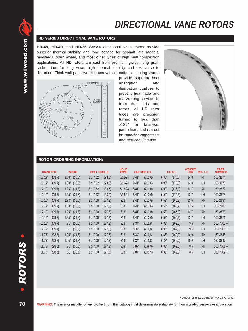
WARNING: The user or installer of any product from this catalog must determine its suitability for their intended purpose or application
www.wilwood.com
70
•R
OT
OR
S•
DIRECTIONAL VANE ROTORS
NOTES: (1) THESE ARE 36 VANE ROTORS
HOLE WEIGHT PARTDIAMETER WIDTH BOLT CIRCLE TYPE FAR SIDE I.D. LUG I.D. LBS RH / LH NUMBER
12.19” (309,7) 1.38” (35,0) 8 x 7.62” (193,6) 5/16-24 8.41” (213,6) 6.90” (175,3) 14.8 RH 160-387412.19” (309,7) 1.38” (35,0) 8 x 7.62” (193,6) 5/16-24 8.41” (213,6) 6.90” (175,3) 14.8 LH 160-387512.19” (309,7) 1.25” (31,8) 8 x 7.62” (193,6) 5/16-24 8.41” (213,6) 6.90” (175,3) 12.7 RH 160-387212.19” (309,7) 1.25” (31,8) 8 x 7.62” (193,6) 5/16-24 8.41” (213,6) 6.90” (175,3) 12.7 LH 160-387312.19” (309,7) 1.38” (35,0) 8 x 7.00” (177,8) .313” 8.41” (213,6) 6.53” (165,9) 13.5 RH 160-268412.19” (309,7) 1.38” (35,0) 8 x 7.00” (177,8) .313” 8.41” (213,6) 6.53” (165,9) 13.5 LH 160-268512.19” (309,7) 1.25” (31,8) 8 x 7.00” (177,8) .313” 8.41” (213,6) 6.53” (165,9) 12.7 RH 160-387012.19” (309,7) 1.25” (31,8) 8 x 7.00” (177,8) .313” 8.41” (213,6) 6.53” (165,9) 12.7 LH 160-387112.19” (309,7) .81” (20,6) 8 x 7.00” (177,8) .313” 8.34” (211,8) 6.38” (162,0) 9.5 RH 160-7705(1)
12.19” (309,7) .81” (20,6) 8 x 7.00” (177,8) .313” 8.34” (211,8) 6.38” (162,0) 9.5 LH 160-7706(1)
11.75” (298,5) 1.25” (31,8) 8 x 7.00” (177,8) .313” 8.34” (211,8) 6.38” (162,0) 10.9 RH 160-384611.75” (298,5) 1.25” (31,8) 8 x 7.00” (177,8) .313” 8.34” (211,8) 6.38” (162,0) 10.9 LH 160-384711.75” (298,5) .81” (20,6) 8 x 7.00” (177,8) .313” 7.87” (199,9) 6.38” (162,0) 8.5 RH 160-7701(1)
11.75” (298,5) .81” (20,6) 8 x 7.00” (177,8) .313” 7.87” (199,9) 6.38” (162,0) 8.5 LH 160-7702(1)
ROTOR ORDERING INFORMATION:
HD-48, HD-40, and HD-36 Series directional vane rotors providesuperior thermal stability and long service for asphalt late models,modifieds, open wheel, and most other types of high heat competitionapplications. All HD rotors are cast from premium grade, long graincarbon iron for long wear, high thermal stability and resistance todistortion. Thick wall pad sweep faces with directional cooling vanes
provide superior heatabsorption anddissipation qualities toprevent heat fade andrealize long service lifefrom the pads androtors. All HD rotorfaces are precisionturned to less than.001" for flatness,parallelism, and run-outfor smoother engagementand reduced vibration.
ROTOR BOLT
CIRCLE
MOUNTING
HOLE
LUG I.D.
FAR SIDE
I.D.
ROTOR
DIAMETER
ROTOR WIDTH
HD SERIES DIRECTIONAL VANE ROTORS:

HOLE WEIGHT PARTDIAMETER WIDTH BOLT CIRCLE TYPE FAR SIDE I.D. LUG I.D. LBS RH / LH NUMBER
12.19” (309,7) 1.25” (31,8) 8 x 8.50” (215,9) .251” 9.10” (231,1) 7.88” (200,2) 8.7 RH 160-457412.19” (309,7) 1.25” (31,8) 8 x 8.50” (215,9) .251” 9.10” (231,1) 7.88” (200,2) 8.7 LH 160-457512.19” (309,7) 1.25” (31,8) 8 x 7.00” (177,8) .325” 8.50” (215,9) 6.38” (162,0) 10.4 RH 160-584512.19” (309,7) 1.25” (31,8) 8 x 7.00” (177,8) .325” 8.50” (215,9) 6.38” (162,0) 10.4 LH 160-584611.75” (298,5) 1.25” (31,8) 8 x 7.00” (177,8) .325” 8.34” (211,8) 6.38” (162,0) 9.6 RH 160-584711.75” (298,5) 1.25” (31,8) 8 x 7.00” (177,8) .325” 8.34” (211,8) 6.38” (162,0) 9.6 LH 160-5848
HOLE WEIGHT PARTDIAMETER WIDTH BOLT CIRCLE TYPE FAR SIDE I.D. LUG I.D. LBS RH / LH NUMBER
12.19” (309,7) 1.25” (31,8) 8 x 7.62” (193,6) 5/16-24 8.50” (215,9) 7.13” (181,1) 10.1 RH 160-290012.19” (309,7) 1.25” (31,8) 8 x 7.62” (193,6) 5/16-24 8.50” (215,9) 7.13” (181,1) 10.1 LH 160-290112.19” (309,7) 1.25” (31,8) 8 x 7.00” (177,8) .325” 8.50” (215,9) 6.38” (162,0) 10.5 RH 160-289412.19” (309,7) 1.25” (31,8) 8 x 7.00” (177,8) .325” 8.50” (215,9) 6.38” (162,0) 10.5 LH 160-289511.75” (298,5) 1.25” (31,8) 8 x 7.00” (177,8) .325” 8.34” (211,8) 6.38” (162,0) 9.6 RH 160-289811.75” (298,5) 1.25” (31,8) 8 x 7.00” (177,8) .325” 8.34” (211,8) 6.38” (162,0) 9.6 LH 160-2899
Brakes are critical safety components, see warnings and disclaimer on page 133
www.wilw
ood.com
71
•R
OT
OR
S•
UL-32 SERIES DIRECTIONAL VANE ROTORS:
Ultra-Light UL-32 and ULHP-32 directional vane rotors provide anexcellent balance of efficient cooling and lower rotating mass on hardbraking dirt tracks or rear axle service on pavement cars. UL rotors arecast from premium grade, long grain carbon iron for long wear, high
thermal stability, andresistance to distortion.UL-32 rotors areproduction machinedand well suited to awide range of sportsmanracing categories.ULHP-32 rotors offeredthe added performanceand smoother operationof precision turnedfaces with less than .001"variation in flatness,parallelism, or run-out.
ROTOR BOLT
CIRCLE
LUG I.D.FAR SIDE
I.D.
MOUNTING
HOLE
ROTOR
DIAMETER
ROTOR WIDTH
ULHP-32 SERIES ROTOR ORDERING INFORMATION:
UL-32 SERIES ROTOR ORDERING INFORMATION:

WARNING: The user or installer of any product from this catalog must determine its suitability for their intended purpose or application
www.wilwood.com
72
•R
OT
OR
S•
STRAIGHT VANE ROTORS
HOLE WEIGHT ROTOR PARTDIAMETER WIDTH BOLT CIRCLE TYPE FAR SIDE I.D. LUG I.D. LBS TYPE NUMBER
12.19” (309,6) .81” (20,6) 8 x 7.78” (197,6) .251” 8.53” (216,7) 7.29” (185,2) 8.7 ULHP-32 160-698412.19” (309,6) .81” (20,6) 8 x 7.78” (197,6) .251” 8.53” (216,7) 7.29” (185,2) 8.7 ULHP-32 160-9585(1)12.19” (309,6) .81” (20,6) 8 x 7.62” (193,6) 5/16-24 8.50” (215,9) 7.13” (181,1) 8.8 ULHP-32 160-584412.19” (309,6) .81” (20,6) 8 x 7.00” (177,8) .325” 8.50” (215,9) 6.38” (162,0) 8.9 ULHP-32 160-584311.75” (298,5) .81” (20,6) 8 x 7.00” (177,8) .325” 8.34” (211,8) 6.38” (162,0) 8.1 ULHP-32 160-584111.00” (279,4) .81” (20,6) 6 x 6.25” (158,8) .325” 7.00” (177,8) 5.59” (142,0) 7.9 ULHP-30 160-584011.00” (279,4) .81” (20,6) 6 x 6.25” (158,8) .325” 7.00” (177,8) 5.59” (142,0) 7.9 ULHP-30 160-10358(1)10.75” (273,1) .81” (20,6) 6 x 6.25” (158,8) .325” 7.00” (177,8) 5.59” (142,0) 7.4 ULHP-30 160-5839
HOLE WEIGHT ROTOR PARTDIAMETER WIDTH BOLT CIRCLE TYPE FAR SIDE I.D. LUG I.D. LBS TYPE NUMBER
12.19” (309,6) .81” (20,6) 8 x 7.00” (177,8) .325” 8.50” (215,9) 6.38” (162,0) 8.9 UL-32 160-027712.00” (304,8) 1.20” (30,5) 8 x 7.00” (177,8) .325” 8.34” (211,8) 6.38” (162,0) 8.6 UL-32 160-058611.75” (298,5) 1.25” (31,8) 10 x 6.81” (173,0) .325” 8.00” (203,2) 6.28” (159,5) 9.5 UL-30 160-078911.75” (298,5) 1.25” (31,8) 8 x 7.00” (177,8) .325” 8.34” (211,8) 6.38” (162,0) 8.8 UL-32 160-048311.75” (298,5) .81” (20,6) 10 x 6.81” (173,0) .325” 8.00” (203,2) 6.28” (159,5) 9.1 UL-30 160-079011.75” (298,5) .81” (20,6) 8 x 7.00” (177,8) .325” 8.34” (211,8) 6.38” (162,0) 8.1 UL-32 160-047111.75” (298,5) .75” (19,6) 8 x 7.62” (193,6) 5/16-24 8.50” (215,9) 7.13” (181,1) 6.9 UL-32 160-194910.50” (266,7) .75” (19,6) 6 x 5.50” (139,7) .325” 6.75” (171,5) 4.94” (125,5) 6.6 UL-30 160-345010.25” (260,4) .75” (19,6) 6 x 5.50” (139,7) .325” 6.75” (171,5) 4.94” (125,5) 6.1 UL-30 160-3747
UL-HP SERIES ROTOR ORDERING INFORMATION:
UL SERIES ROTOR ORDERING INFORMATION:
Ultra-Light UL and ULHP straight vane rotors provide high valueperformance and rugged durability for a wide range of competition, highperformance, and sport driving applications. Don't confuse these rotorswith bargain priced off-brand named parts. Wilwood's modernmanufacturing capability, combined with large scale economies, make itpossible to offer this level of quality and performance at such anaffordable price.
Every Wilwood rotor is cast from premium grade, long grain carbon iron.This material exhibits long wear, high thermal stability, and excellentresistance to distortion in high heat. Modern foundry and machiningtechniques hold close tolerances on face and vane thickness. Combining
the correct facethickness with a 30 or32 vane castingprovides superior heatmanagement and longservice life with lowrotating and unsprung weight. The straight vane design also makesit possible to use the same rotor on left or right hand mountinglocations.
UL series rotors are production machined and will provide excellentservice for many applications. ULHP series rotors provide theadditional performance and smoother operation of precisionmachined faces with less than .001" variation in flatness,parallelism, and run-out.
ROTOR WIDTH
MOUNTING
HOLE
ROTOR
DIAMETER
ROTOR
BOLT CIRCLE
FAR SIDE
I.D.LUG I.D
8 Bolt Configuration
UL SERIES STRAIGHT VANE ROTORS:
NOTES: (1) THIS ROTOR HAS A UNIQUE ASYMMETRICAL FACE GROOVE PATTERN

Brakes are critical safety components, see warnings and disclaimer on page 133
www.wilw
ood.com
73
•R
OT
OR
S•
LIGHTENED STRAIGHT VANE ROTORSWhen it comes to rotors, racers are constantly searching for the ultimate balance between the lowest weight and theability to effectively manage heat. Decreased rotating weight in the drive line provides quicker deceleration under brakingand quicker acceleration out of the corners. Lower weight also benefits handling with improved spring and shock controlover the unsprung suspension mass. Wilwood's ULD-32 drilled and ULS-32 scalloped iron rotors provide two highlyeffective lightweight options for sprints, late models, modifieds, and other competition applications that race in low tomedium temperature ranges.
ULD-32 Series Drilled Straight VaneVented Iron Rotors feature a two row,64 hole pattern that alternates betweenand directly over each vane. Each holeis deeply chamfered to eliminate anystress points that could result inpremature cracking at the drill holes.The drilling process removes anaverage of one pound from each rotor.Rotating and unsprung rotor mass isreduced by as much as 12%.
Caution on drilled rotors: There is acommon mis-perception that rotors are
drilled to improve cooling. The reduced mass of a drilled rotor will dissipate its retained heat quicker, but it also builds upheat at a much faster rate. The decision to use drilled rotors should be solely based on the merits of the lower rotatingand unsprung weight, and not for improved cooling. It is not wise to use drilled rotors in sustained high heat on hardbraking tracks unless the team budget affords a high frequency of rotor and brake pad replacement.
ULS-32 Series Scalloped Rotorsfeature a fully machined scallopconfiguration that provides the highestdegree of weight reduction on a ventedstraight vane iron rotor. Scallopmachining will remove as much as threepounds, or nearly 33% of the rotormass. The vented castings provideincreased cooling capacity overmachined steel plate rotors, withimproved structural durability overdrilled rotor designs.
ROTOR WIDTH
MOUNTING
HOLE
ROTOR
DIAMETER
ROTOR
BOLT CIRCLE
FAR SIDE
I.D.LUG I.D
ROTOR
DIAMETER
ROTOR WIDTH
LUG I.D.
FAR SIDE
I.D.
ROTORBOLT
CIRCLE
MOUNTING HOLE
HOLE WEIGHT ROTOR PARTDIAMETER WIDTH BOLT CIRCLE TYPE FAR SIDE I.D. LUG I.D. LBS TYPE NUMBER
12.19” (309,6) .81” (20,6) 8 x 7.00” (177,8) .325” 8.50” (215,9) 6.38” (162,0) 8.0 ULD-32 160-586511.75” (298,5) 1.25” (31,8) 8 x 7.00” (177,8) .325” 8.34” (211,8) 6.38” (162,0) 7.7 ULD-32 160-586411.75” (298,5) .81” (20,6) 8 x 7.00” (177,8) .325” 8.34” (211,8) 6.38” (162,0) 7.2 ULD-32 160-5863
ULD-32 SERIES ROTOR ORDERING INFORMATION:
HOLE WEIGHT ROTOR PARTDIAMETER WIDTH BOLT CIRCLE TYPE FAR SIDE I.D. LUG I.D. LBS TYPE NUMBER
12.19” (309,6) .81” (20,6) 8 x 7.00” (177,8) .325” 8.50” (215,9) 6.38” (162,0) 5.9 ULS-32 160-813611.75” (298,5) 1.25” (31,8) 8 x 7.00” (177,8) .325” 8.34” (211,8) 6.38” (162,0) 5.8 ULS-32 160-834311.75” (298,5) 1.25” (31,8) 8 x 7.00” (177,8) .325” 8.75” (222,2) 6.38” (162,0) 6.7 ULS-32 160-881411.75” (298,5) .81” (20,6) 8 x 7.00” (177,8) .325” 8.34” (211,8) 6.38” (162,0) 5.4 ULS-32 160-813510.50” (266,7) .81” (20,6) 6 x 5.50” (139,7) .325” 7.30” (185,4) 4.94” (125,5) 2.9 ULS-24 160-9363(1)10.50” (266,7) .75” (19,1) 6 x 5.50” (139,7) .325” 7.30” (185,4) 4.94” (125,5) 3.8 ULS-32 160-8427
ULS-32 SERIES ROTOR ORDERING INFORMATION:
ULD-32 SERIES DRILLED STRAIGHT VANE VENTED IRON ROTORS:
ULS-32 SERIES SCALLOPED VENTED IRON ROTORS:
NOTE: (1) THIS ROTOR IS TITANIUM POLYMETALLIC COATED
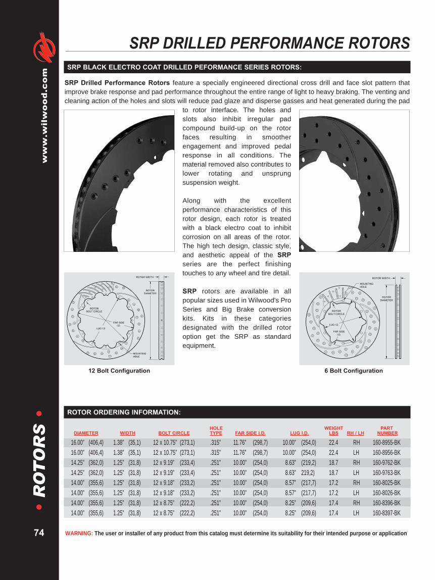
WARNING: The user or installer of any product from this catalog must determine its suitability for their intended purpose or application
www.wilwood.com
74
•R
OT
OR
S•
SRP DRILLED PERFORMANCE ROTORS
SRP Drilled Performance Rotors feature a specially engineered directional cross drill and face slot pattern thatimprove brake response and pad performance throughout the entire range of light to heavy braking. The venting andcleaning action of the holes and slots will reduce pad glaze and disperse gasses and heat generated during the pad
to rotor interface. The holes andslots also inhibit irregular padcompound build-up on the rotorfaces resulting in smootherengagement and improved pedalresponse in all conditions. Thematerial removed also contributes tolower rotating and unsprungsuspension weight.
Along with the excellentperformance characteristics of thisrotor design, each rotor is treatedwith a black electro coat to inhibitcorrosion on all areas of the rotor.The high tech design, classic style,and aesthetic appeal of the SRPseries are the perfect finishingtouches to any wheel and tire detail.
SRP rotors are available in allpopular sizes used in Wilwood's ProSeries and Big Brake conversionkits. Kits in these categoriesdesignated with the drilled rotoroption get the SRP as standardequipment.
MOUNTING
HOLE
ROTOR
BOLT CIRCLE
FAR SIDE
I.D.
LUG I.D
ROTOR WIDTH
ROTOR
DIAMETER
6 Bolt Configuration
MOUNTING
HOLE
ROTOR
BOLT CIRCLE
FAR SIDE
I.D.
LUG I.D
ROTOR WIDTH
ROTOR
DIAMETER
12 Bolt Configuration
HOLE WEIGHT PARTDIAMETER WIDTH BOLT CIRCLE TYPE FAR SIDE I.D. LUG I.D. LBS RH / LH NUMBER
16.00” (406,4) 1.38” (35,1) 12 x 10.75” (273,1) .315” 11.76” (298,7) 10.00” (254,0) 22.4 RH 160-8955-BK16.00” (406,4) 1.38” (35,1) 12 x 10.75” (273,1) .315” 11.76” (298,7) 10.00” (254,0) 22.4 LH 160-8956-BK14.25” (362,0) 1.25” (31,8) 12 x 9.19” (233,4) .251” 10.00” (254,0) 18.63” (219,2) 18.7 RH 160-9762-BK14.25” (362,0) 1.25” (31,8) 12 x 9.19” (233,4) .251” 10.00” (254,0) 18.63” 219,2) 18.7 LH 160-9763-BK14.00” (355,6) 1.25” (31,8) 12 x 9.18” (233,2) .251” 10.00” (254,0) 18.57” (217,7) 17.2 RH 160-8025-BK14.00” (355,6) 1.25” (31,8) 12 x 9.18” (233,2) .251” 10.00” (254,0) 18.57” (217,7) 17.2 LH 160-8026-BK14.00” (355,6) 1.25” (31,8) 12 x 8.75” (222,2) .251” 10.00” (254,0) 18.25” (209,6) 17.4 RH 160-8396-BK14.00” (355,6) 1.25” (31,8) 12 x 8.75” (222,2) .251” 10.00” (254,0) 18.25” (209,6) 17.4 LH 160-8397-BK
ROTOR ORDERING INFORMATION:
SRP BLACK ELECTRO COAT DRILLED PEFORMANCE SERIES ROTORS:

HOLE WEIGHT PARTDIAMETER WIDTH BOLT CIRCLE TYPE FAR SIDE I.D. LUG I.D. LBS RH / LH NUMBER
14.00” (355,6) 1.10” (27,9) 12 x 9.18” (233,2) .251” 10.00” (254,0) 8.57” (217,7) 14.3 RH 160-8099-BK14.00” (355,6) 1.10” (27,9) 12 x 9.18” (233,2) .251” 10.00” (254,0) 8.57” (217,7) 14.3 LH 160-8100-BK14.00” (355,6) 1.10” (27,9) 12 x 8.75” (222,2) .251” 10.00” (254,0) 8.25” (209,6) 14.5 RH 160-8400-BK14.00” (355,6) 1.10” (27,9) 12 x 8.75” (222,2) .251” 10.00” (254,0) 8.25” (209,6) 14.5 LH 160-8401-BK13.06” (331,7) 1.25” (31,8) 12 x 8.75” (222,2) .251” 9.46” (240,3) 8.25” (209,6) 12.3 RH 160-7798-BK13.06” (331,7) 1.25” (31,8) 12 x 8.75” (222,2) .251” 9.46” (240,3) 8.25” (209,6) 12.3 LH 160-7799-BK13.00” (330,2) 1.10” (27,9) 12 x 7.00” (177,8) .251” 8.57” (217,7) 6.38” (162,0) 14.4 RH 160-8510-BK13.00” (330,2) 1.10” (27,9) 12 x 7.00” (177,8) .251” 8.57” (217,7) 6.38” (162,0) 14.4 LH 160-8511-BK12.90” (327,7) 1.25” (31,8) 12 x 8.75” (222,2) .251” 9.46” (240,3) 8.25” (209,6) 11.5 RH 160-7172-BK12.90” (327,7) 1.25” (31,8) 12 x 8.75” (222,2) .251” 9.46” (240,3) 8.25” (209,6) 11.5 LH 160-7173-BK12.90” (327,7) 1.10” (27,9) 12 x 8.75” (222,2) .251” 9.46” (240,3) 8.25” (209,6) 11.9 RH 160-6835-BK12.90” (327,7) 1.10” (27,9) 12 x 8.75” (222,2) .251” 9.46” (240,3) 8.25” (209,6) 11.9 LH 160-6836-BK12.90” (327,7) 1.00” (25,4) 12 x 8.75” (222,2) .251” 9.46” (240,3) 8.25” (209,6) 10.4 RH 160-8006-BK12.90” (327,7) 1.00” (25,4) 12 x 8.75” (222,2) .251” 9.46” (240,3) 8.25” (209,6) 10.4 LH 160-8007-BK12.90” (327,7) .81” (20,6) 12 x 8.75” (222,2) .251” 9.46” (240,3) 8.25” (209,6) 10.1 RH 160-9961-BK12.90” (327,7) .81” (20,6) 12 x 8.75” (222,2) .251” 9.46” (240,3) 8.25” (209,6) 10.1 LH 160-9962-BK12.80” (325,1) 1.25” (31,8) 12 x 7.06” (179,3) .251” 8.41” (213,6) 6.53” (165,9) 14.5 RH 160-7744-BK12.80” (325,1) 1.25” (31,8) 12 x 7.06” (179,3) .251” 8.41” (213,6) 6.53” (165,9) 14.5 LH 160-7745-BK12.80” (325,1) 1.25” (31,8) 5 x 4.75” (120,7) – 8.53” (216,7) – – 18.7 RH 160-9334-BK(1)
12.80” (325,1) 1.25” (31,8) 5 x 4.75” (120,7) – 8.53” (216,7) – – 18.7 LH 160-9335-BK(1)
12.40” (315,0) 1.10” (27,9) 12 x 6.75” (171,5) .251” 8.41” (213,6) 6.18” (157,0) 14.0 RH 160-8706-BK12.40” (315,0) 1.10” (27,9) 12 x 6.75” (171,5) .251” 8.41” (213,6) 6.18” (157,0) 14.0 LH 160-8707-BK12.19” (309,6) .81” (20,6) 8 x 7.78” (197,6) .251” 8.53” (216,7) 7.29” (185,2) 8.6 RH 160-6924-BK12.19” (309,6) .81” (20,6) 8 x 7.78” (197,6) .251” 8.53” (216,7) 7.29” (185,2) 8.6 LH 160-6925-BK12.19” (309,6) .81” (20,6) 8 x 7.78” (197,6) .251” 8.53” (216,7) 7.29” (185,2) 8.5 RH 160-6986-BK12.19” (309,6) .81” (20,6) 8 x 7.78” (197,6) .215” 8.53” (216,7) 7.29” (185,2) 8.5 LH 160-6987-BK12.19” (309,6) .81” (20,6) 8 x 7.62” (193,6) 5/16-24 8.50” (215,9) 7.13” (181,1) 8.6 RH 160-7105-BK12.19” (309,6) .81” (20,6) 8 x 7.62” (193,6) 5/16-24 8.50” (215,9) 7.13” (181,1) 8.6 LH 160-7106-BK12.19” (309,6) .81” (20,6) 8 x 7.00” (177,8) .325” 8.50” (215,9) 6.38” (162,0) 8.8 RH 160-7103-BK12.19” (309,6) .81” (20,6) 8 x 7.00” (177,8) .325” 8.50” (215,9) 6.38” (162,0) 8.8 LH 160-7104-BK12.00” (304,8) .81” (20,6) 8 x 7.00” (177,8) .325” 8.41” (213,6) 6.38” (162,0) 8.3 RH 160-8496-BK12.00” (304,8) .81” (20,6) 8 x 7.00” (177,8) .325” 8.41” (213,6) 6.38” (162,0) 8.3 LH 160-8497-BK11.75” (298,5) .81” (20,6) 8 x 7.00” (177,8) .325” 8.34” (211,9) 6.38” (162,0) 8.0 RH 160-7101-BK11.75” (298,5) .81” (20,6) 8 x 7.00” (177,8) .325” 8.34” (211,9) 6.38” (162,0) 8.0 LH 160-7102-BK11.66” (296,2) .72” (18,3) 8 x 7.00” (177,8) .325” 8.25” (209,6) 6.38” (162,0) 7.1 RH 160-8592-BK11.66” (296,2) .72” (18,3) 8 x 7.00” (177,8) .325” 8.25” (209,6) 6.38” (162,0) 7.1 LH 160-8593-BK11.00” (279,4) .81” (20,6) 6 x 6.25” (158,8) .325” 7.00” (177,8) 5.59” (142,0) 7.7 RH 160-709-BK11.00” (279,4) .81” (20,6) 6 x 6.25” (158,8) .325” 7.00” (177,8) 5.59” (142,0) 7.7 LH 160-7100-BK10.75” (273,1) .81” (20,6) 6 x 6.25” (158,8) .325” 7.00” (177,8) 5.59” (142,0) 7.2 RH 160-7097-BK10.75” (273,1) .81” (20,6) 6 x 6.25” (158,8) .325” 7.00” (177,8) 5.59” (142,0) 7.2 LH 160-7098-BK10.50” (266,7) .75” (19,6) 6 x 5.50” (139,7) .325” 6.75” (171,5) 4.94” (125,5) 6.4 RH 160-9249-BK10.50” (266,7) .75” (19,6) 6 x 5.50” (139,7) .325” 6.75” (171,5) 4.94” (125,5) 6.4 LH 160-9250-BK
Brakes are critical safety components, see warnings and disclaimer on page 133
www.wilw
ood.com
75
•R
OT
OR
S•
ROTOR ORDERING INFORMATION:
NOTES: (1) THESE ARE ONE PIECE HAT/ROTOR COMBINATION ROTORS UTILIZED AS OEM REPLACEMENTS FOR FRONT C-5, C-6 CORVETTE

WARNING: The user or installer of any product from this catalog must determine its suitability for their intended purpose or application
www.wilwood.com
76
•R
OT
OR
S•
DISC / DRUM ROTORS FOR INTERNAL PARKING BRAKES
For custom, show, and high performance sport driving, SRP rotors offer thehigh tech look and improved performance of a directional cross-drill and faceslot pattern. In addition to the aesthetic appeal, the venting and cleaning actionof the hole and slot pattern helps to reduce pad glaze and minimize irregular
pad build-up on therotor faces. The resultsare a smootherengagement feel at thepedal and consistentresponse from thepads. Each rotor isprecision machined toless than .001"tolerance for overallflatness, parallelism,and radial run-out onlong grain carbon iron castings. The rotors are finished witha black electro coat to provide corrosion resistance.
SRP Drilled & Slotted .81” Vented Rotor
STUD FACE CENTER ROTOR PARTDIAMETER WIDTH LUG PATTERN HOLE OFFSET SHOE I.D. THICKNESS HOLE TYPE NUMBER13.70” (348,0) .79” (20,1) 6 on 5.31” .62” 3.16” 8.98” .34” 3.55” SRP-RH 160-9098-BK13.70” (348,0) .79” (20,1) 6 on 5.31” .62” 3.16” 8.98” .34” 3.55” SRP-LH 160-9099-BK12.75” (323,9) .80” (20,3) 6 on 5.50” .65” 2.30” 8.27” .24” 3.10” SRP-RH 160-8958-BK12.75” (323,9) .80” (20,3) 6 on 5.50” .65” 2.30” 8.27” .24” 3.10” SRP-LH 160-8959-BK12.27” (311,7) .78” (19,8) 5 on 4.75” .58” 2.08” 7.08” .34” 2.96” SRP-RH 160-8685-BK12.27” (311,7) .78” (19,8) 5 on 4.75” .58” 2.08” 7.08” .34” 2.96” SRP-LH 160-8686-BK12.19” (309,6) .81” (20,6) 5 on 4.75” .45/.48/.52” 2.32 7.24 .18” 2.78” SRP-RH 160-10050-BK12.19” (309,6) .81” (20,6) 5 on 4.75” .45/.48/.52” 2.32 7.24 .18” 2.78” SRP-LH 160-10051-BK12.19” (309,6) .81” (20,6) 5 on 4.50/4.75/5.00” .52” 2.32” 7.24” .18” 3.06” SRP-RH 160-6970-BK12.19” (309,6) .81” (20,6) 5 on 4.50/4.75/5.00” .52” 2.32' 7.24” .18” 3.06” SRP-LH 160-6971-BK12.19” (309,6) .81” (20,6) 5 on 4.50/4.75/5.00” .52” 1.91” 7.24” .18” 3.12” SRP-RH 160-9989-BK12.19” (309,6) .81” (20,6) 5 on 4.50/4.75/5.00” .52” 1.91” 7.24” .18” 3.12” SRP-LH 160-9990-BK12.19” (309,6) .81” (20,6) 5 on 4.50/4.75/5.00” .52” 1.91” 7.24” .18” 2.78” SRP-RH 160-9812-BK12.19” (309,6) .81” (20,6) 5 on 4.50/4.75/5.00” .52” 1.91” 7.24” .18” 2.78” SRP-LH 160-9813-BK12.19” (309,6) .81” (20,6) 5 on 4.75” .52” 2.31” 7.48” .21” 2.76” SRP-RH 160-8744-BK12.19” (309,6) .81” (20,6) 5 on 4.75” .52” 2.31” 7.48” .21” 2.76” SRP-LH 160-8745-BK12.19” (309,6) .81” (20,6) Undrilled — 2.32” 7.24” .18” 2.78” SRP-RH 160-8866-BK12.19” (309,6) .81” (20,6) Undrilled — 2.32” 7.24” .18” 2.78” SRP-LH 160-8867-BK12.19” (309,6) .81” (20,6) Undrilled — 1.91” 7.24” .18” 2.78” SRP-RH 160-6972-BK12.19” (309,6) .81” (20,6) Undrilled — 1.91” 7.24” .18” 2.78” SRP-LH 160-6973-BK12.19” (309,6) .50” (12,7) Undrilled — 1.74” 7.24” .18” 2.80” SRP-RH 160-6964-BK12.19” (309,6) .50” (12,7) Undrilled — 1.74” 7.24” .18” 2.80” SRP-LH 160-6965-BK12.00” (304,8) 1.03” (26,2) 5 on 4.75” .53” .64” 7.48” .26” 2.78” SRP-RH 160-7767-BK12.00” (304,8) 1.03” (26,2) 5 on 4.75” .53” .64” 7.48” .26” 2.78” SRP-LH 160-7768-BK11.00” (279,4) .81” (20,6) 5 on 4.50/4.75/5.00” .52” 1.75” 6.88” .19” 2.80” SRP-RH 160-10327-BK11.00” (279,4) .81” (20,6) 5 on 4.50/4.75/5.00” .52” 1.75” 6.88” .19” 2.80” SRP-LH 160-10328-BK
SRP BLACK ELECTRO COAT DRILLED PEFORMANCE ROTORS ORDERING INFORMATION:
SRP BLACK ELECTRO COAT DRILLED PEFORMANCE SERIES ROTORS:
ROTOR
DIAMETER
STUD
BOLT CIRCLE
FACE
THICKNESSPERFORMANCE
DRILLED
CENTER HOLE
DIAMETER
CLEARANCE
I.D.
ROTOR WIDTH OFFSET
Typical Dimensional Reference Guide

Brakes are critical safety components, see warnings and disclaimer on page 133
www.wilw
ood.com
77
•R
OT
OR
S•
STUD FACE CENTER ROTOR PARTDIAMETER WIDTH LUG PATTERN HOLE OFFSET SHOE I.D. THICKNESS HOLE TYPE NUMBER12.19” (309,6) .81” (20,6) 5 on 4.50/4.75/5.00” .52” 2.32” 7.24” .18” 3.06” HP-R/L 160-686512.19” (309,6) .81” (20,6) 5 on 4.50/4.75/5.00” .52” 2.32” 7.24” .20” 2.78” HP-R/L 160-931412.19” (309,6) .81” (20,8) 5 on 4.50/4.75/5.00” .52” 1.91” 7.24” .18” 3.12” HP-R/L 160-998712.19” (309,6) .81” (20,6) 5 on 4.50/4.75/5.00” .52” 1.91” 7.24” .18” 2.78” HP-R/L 160-750812.19” (309,6) .81” (20,6) 5 on 4.75” .45/.48/.52” 2.32” 7.24” .18” 2.78” HP-R/L 160-1004912.19” (309,6) .81” (20,6) Undrilled — 2.32” 7.24” .18” 2.78” HP-R/L 160-886512.19” (309,6) .81” (20,6) Undrilled — 1.91” 7.24” .18” 2.78” HP-R/L 160-686812.19” (309,6) .50” (12,7) Undrilled — 1.74” 7.24” .18” 2.80” HP-R/L 160-672211.00” (279,4) .81” (20,6) 5 on 4.50/4.75/5.00” .52” 1.75” 6.88” .19” 2.80” HP-R/L 160-10326
HP PERFORMANCE ROTORS ORDERING INFORMATION:
HP rotors are close tolerance machined with smooth turned pad faces. Theadditional mass of the HP series extends service life on heavier competitionvehicles and other severe duty applications. They are also the base model forevery day use.
Each rotor is precision machined to less than .001" tolerance for overall flatness,parallelism, and radial run-out on long grain carbon iron castings. Long graincarbon iron is used for its superior thermal conductivity and stability propertiesthat resist distortion and fatigue.
HP PERFORMANCE SERIES ROTORS:
HP Smooth Face Rotor
STUD FACE CENTER ROTOR PARTDIAMETER WIDTH LUG PATTERN HOLE OFFSET SHOE I.D. THICKNESS HOLE TYPE NUMBER13.70” (348,0) .79” (20,1) 6 on 5.31” .62” 3.16” 8.98” .34” 3.55” GT-R/L 160-909713.00” (330,2) 1.15” (29,2) 8 on 6.50” .63” 1.90” 8.12” .32” 4.63” GT-R/L 160-887512.75” (323,9) .80” (20,3) 6 on 5.50” .65” 2.30” 8.27” .24” 3.10” GT-R/L 160-895712.27” (311,7) .78” (19,8) 5 on 4.75” .58” 2.08” 7.08” .34” 2.96” GT-RH 160-868312.27” (311,7) .78” (19,8) 5 on 4.75” .58” 2.08” 7.08” .34” 2.96” GT-LH 160-868412.19” (309,6) .81” (20,6) 5 on 4.75” .52” 2.31” 7.48” .21” 2.76” GT-R/L 160-874312.00” (304,8) 1.03” (26,2) 5 on 4.75” .53” .64” 7.48” .26” 2.78” GT-RH 160-801312.00” (304,8) 1.03” (26,2) 5 on 4.75” .53” .64” 7.48” .26” 2.78” GT-LH 160-8014
GT COMPETITION ROTORS ORDERING INFORMATION:
GT rotors feature Wilwood's ultimate competition preparation with full detailmachining, asymmetrical face slotting, and individual dynamic balancing. Fulldetail machining eliminates unnecessary weight and potential stress points. Theventing and cleaning action of the asymmetrical face slot pattern helps to reducepad glaze, minimize irregular pad build-up on the rotor faces, and interruptengagement harmonics.
GT rotors run smooth, true, and vibration free at all speeds with the highestlevels of performance in sustained high heat conditions.
GT COMPETITION SERIES ROTORS:
GT Slotted Rotor
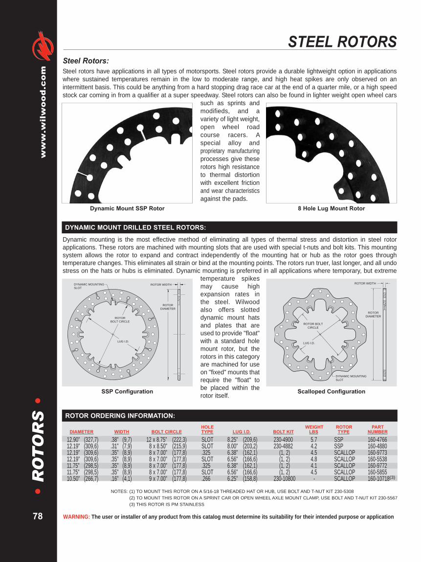
WARNING: The user or installer of any product from this catalog must determine its suitability for their intended purpose or application
www.wilwood.com
78
•R
OT
OR
S•
STEEL ROTORS
NOTES: (1) TO MOUNT THIS ROTOR ON A 5/16-18 THREADED HAT OR HUB, USE BOLT AND T-NUT KIT 230-5308(2) TO MOUNT THIS ROTOR ON A SPRINT CAR OR OPEN WHEEL AXLE MOUNT CLAMP, USE BOLT AND T-NUT KIT 230-5567(3) THIS ROTOR IS PM STAINLESS
HOLE WEIGHT ROTOR PARTDIAMETER WIDTH BOLT CIRCLE TYPE LUG I.D. BOLT KIT LBS TYPE NUMBER
12.90” (327,7) .38” (9,7) 12 x 8.75” (222,3) SLOT 8.25” (209,6) 230-4900 5.7 SSP 160-476612.19” (309,6) .31” (7,9) 8 x 8.50” (215,9) SLOT 8.00” (203,2) 230-4882 4.2 SSP 160-488012.19” (309,6) .35” (8,9) 8 x 7.00” (177,8) .325 6.38” (162,1) (1, 2) 4.5 SCALLOP 160-977312.19” (309,6) .35” (8,9) 8 x 7.00” (177,8) SLOT 6.56” (166,6) (1, 2) 4.8 SCALLOP 160-553811.75” (298,5) .35” (8,9) 8 x 7.00” (177,8) .325 6.38” (162,1) (1, 2) 4.1 SCALLOP 160-977211.75” (298,5) .35” (8,9) 8 x 7.00” (177,8) SLOT 6.56” (166,6) (1, 2) 4.5 SCALLOP 160-585510.50” (266,7) .16” (4,1) 9 x 7.00” (177,8) .266 6.25” (158,8) 230-10800 - SCALLOP 160-10718(3)
ROTOR ORDERING INFORMATION:
Steel Rotors:Steel rotors have applications in all types of motorsports. Steel rotors provide a durable lightweight option in applicationswhere sustained temperatures remain in the low to moderate range, and high heat spikes are only observed on anintermittent basis. This could be anything from a hard stopping drag race car at the end of a quarter mile, or a high speedstock car coming in from a qualifier at a super speedway. Steel rotors can also be found in lighter weight open wheel cars
such as sprints andmodifieds, and avariety of light weight,open wheel roadcourse racers. Aspecial alloy andproprietary manufacturingprocesses give theserotors high resistanceto thermal distortionwith excellent frictionand wear characteristicsagainst the pads.
Dynamic mounting is the most effective method of eliminating all types of thermal stress and distortion in steel rotorapplications. These rotors are machined with mounting slots that are used with special t-nuts and bolt kits. This mountingsystem allows the rotor to expand and contract independently of the mounting hat or hub as the rotor goes throughtemperature changes. This eliminates all strain or bind at the mounting points. The rotors run truer, last longer, and all undostress on the hats or hubs is eliminated. Dynamic mounting is preferred in all applications where temporary, but extreme
temperature spikesmay cause highexpansion rates inthe steel. Wilwoodalso offers slotteddynamic mount hatsand plates that areused to provide "float"with a standard holemount rotor, but therotors in this categoryare machined for useon "fixed" mounts thatrequire the "float" tobe placed within therotor itself.
ROTOR WIDTH
ROTOR
DIAMETER
ROTOR
BOLT CIRCLE
LUG I.D.
DYNAMIC MOUNTING
SLOT
SSP Configuration
DYNAMIC MOUNTING
SLOT
ROTOR WIDTH
ROTOR BOLT
CIRCLE
LUG I.D.
ROTOR
DIAMETER
Scalloped Configuration
8 Hole Lug Mount RotorDynamic Mount SSP Rotor
DYNAMIC MOUNT DRILLED STEEL ROTORS:

These rotors are most often directly mounted to "fixed" mount hats or mounting plates, but they can also be used withspecial dynamic slotted mount hats or plates that require the use of a standard hole mount disc. Each rotor size isavailable in the standard solid plate style, or weight drilled for lighter duty applications.
Brakes are critical safety components, see warnings and disclaimer on page 133
www.wilw
ood.com
79
•R
OT
OR
S•
STANDARD HOLE MOUNT STEEL ROTORS:
NOTES: (1) THIS ROTOR IS POLYMETALLIC PLASMA COATED
ROTOR
DIAMETER
ROTOR WIDTH
LUG I.D.
ROTORBOLT
CIRCLE
MOUNTING
HOLE
ACCESS HOLE
6 x 5.50” Lug Mount
MOUNTING
HOLE
ROTOR WIDTH
ROTOR BOLT
CIRCLE
LUG I.D.
ROTOR
DIAMETER
8 Bolt Lug Mount
MOUNTING
HOLE
ROTOR WIDTH
ROTOR BOLT
CIRCLE
LUG I.D.
ROTOR
DIAMETER
6 x 6.25” Lug Mount
MOUNTING
HOLE
ROTOR WIDTH
ROTOR BOLT
CIRCLE
LUG
I.D.
ROTOR
DIAMETER
3 x 5.00” Lug Mount
MOUNTING
HOLE
ROTOR WIDTH
ROTOR BOLT
CIRCLE
ROTOR
DIAMETER
5 x 3.88” Flange Window Mount
MOUNTING
HOLE
ROTOR WIDTH
ROTOR BOLT
CIRCLE
LUG I.D.
ROTOR
DIAMETER
5 x 5.00” Lug Mount
HOLE WEIGHT ROTOR PARTDIAMETER WIDTH BOLT CIRCLE TYPE LUG I.D. LBS TYPE NUMBER
11.00” (279,4) .31” (7,9) 3 x 5.00” (127,0) .500” 4.10” (104,1) 4.6 DRILLED 160-208411.00” (279.4) .31” (7,9) 3 x 5.00” (127,0) .500” 4.10” (104,1) 3.3 DRILLED 160-1047510.25” (260,4) .31” (7,9) 3 x 5.00” (127,0) .500” 4.10” (104,1) 4.1 DRILLED 160-345810.00” (254,0) .32” (8,2) 5 x 3.88” (98,6) .391” 3.12” (79,2) 5.2 SOLID 160-218110.00” (254,0) .32” (8,2) 5 x 3.88” (98,6) .391” 3.12” (79,2) 4.8 DRILLED 160-218210.00” (254,0) .25” (6,4) 5 x 5.00” (127,0) .391” 4.10” (104,1) 3.6 SOLID 160-086710.00” (254,0) .25” (6,4) 5 x 5.00” (127,0) .391” 4.10” (104,1) 3.2 DRILLED 160-160219.88” (250,9) .19” (4,8) 3 x 5.00” (127,0) .500” 4.10” (104,1) 2.6 DRILLED 160-8621(1)
3 AND 5 BOLT ROTOR ORDERING INFORMATION:
HOLE WEIGHT ROTOR PARTDIAMETER WIDTH BOLT CIRCLE TYPE LUG I.D. LBS TYPE NUMBER
12.00” (304,8) .31” (7,9) 8 x 7.62” (193,6) 5/16-24 7.00” (177,8) 5.3 SOLID 160-049012.00” (304,8) .31” (7,9) 8 x 7.62” (193,6) 5/16-24 7.00” (177,8) 4.6 DRILLED 160-049512.00” (304,8) .35” (8,9) 8 x 7.00” (177,8) .325” 6.38” (162,0) 6.0 SOLID 160-052412.00” (304,8) .35” (8,9) 8 x 7.00” (177,8) .325” 6.38” (162,0) 5.4 DRILLED 160-052511.75” (298,5) .35” (8,9) 8 x 7.00” (177,8) .325” 6.38” (162,0) 5.9 SOLID 160-320111.75” (298,5) .35” (8,9) 8 x 7.00” (177,8) .325” 6.38” (162,0) 5.3 DRILLED 160-320211.44” (290,6) .35” (8,9) 8 x 7.00” (177,8) .325” 6.38” (162,0) 5.4 SOLID 160-020111.44” (290,6) .35” (8,9) 8 x 7.00” (177,8) .325” 6.38” (162,0) 4.7 DRILLED 160-160111.44” (290,6) .35” (8,9) 8 x 7.00” (177,8) .316” 6.38” (162,0) 5.4 SOLID 160-766310.75” (273,1) .35” (8,9) 6 x 6.25” (158,5) .316” 5.54” (142,0) 5.2 SOLID 160-330510.75” (273,1) .35” (8,9) 6 x 6.25” (158,5) .316” 5.54” (142,0) 4.7 DRILLED 160-330610.50” (266,7) .35” (8,9) 6 X 5.50” (139,7) .325” 4.94” (125,5) 5.2 SOLID 160-1002110.50” (266,7) .35” (8,9) 6 X 5.50” (139,7) .325” 4.94” (125,5) 4.7 DRILLED 160-345510.25” (260,4) .35” (8,9) 6 X 5.50” (139,7) .325” 4.94” (125,5) 4.6 DRILLED 160-3748
6 AND 8 BOLT ROTOR ORDERING INFORMATION:

WARNING: The user or installer of any product from this catalog must determine its suitability for their intended purpose or application
www.wilwood.com
80
•R
OT
OR
S•
ALUMINUM ROTORSWARNING: SPECIAL RACING APPLICATION ONLY
ALUMINUM ROTORS ARE UNSAFE FOR STREET USE • ALUMINUM ROTORS ARE NOT SUITABLE FOR MOSTFORMS OF RACING AND CAN RESULT IN CATASTROPHIC FAILURE WHEN MISUSED
READ DISCLAIMER OF WARRANTY LOCATED AT THE REAR OF THE MANUAL
Wilwood's 3 hole mount rotors are precision CNC machined from high strength billet plate. Full symmetricalmachining provides perfect balance, perfect flatness and the truest rotation of any rotor being built. These rotors fitthe popular 3 x 5.00" mount bolt circle found on most sprint and midget front hubs. Wilwood's engineered drill and
relief slot pattern combines the highestdegree of weight reduction with thehighest resistance to thermal distortion inthe contact faces. You get smoothengagement and a consistent full pedalfrom the low knock-back characteristicsof this design. A durable black anodizedfinish prevents corrosion and simplifiesthe visual inspection of the contactfaces. The best results are alwaysachieved using PolyMatrix Q compoundbrake pads with these rotors.
MOUNTING
HOLE
ROTOR WIDTH
ROTOR BOLT
CIRCLE
ROTOR
DIAMETER
3 HOLE MOUNT ALUMINUN ROTORS:
WEIGHT PARTDIAMETER WIDTH BOLT CIRCLE LBS ROTOR TYPE NUMBER
10.95” (278,1) .31” (7,9) 3 x 42 SPLINE 2.3 DRILLED 160-327510.20” (259,1) .31” (7,9) 3 x 42 SPLINE 1.9 DRILLED 160-3270
SPLINED MOUNT ROTOR ORDERING INFORMATION:
Wilwood's 3.00" x 42 splined axle mount rotors are manufactured from the same high strength billets with the sameprecision as our 3 hole mount front rotors. Full symmetrical machining provides perfect balance, perfect flatness andthe truest rotation of any aluminum rotor being built. Wilwood's engineered drill and relief slot pattern combines the
highest degree of weight reduction withthe highest resistance to thermaldistortion in the contact faces. You getsmooth engagement and a consistentfull pedal from the low knock-backcharacteristics of this design. A durableblack anodized finish prevents corrosionand simplifies the visual inspection of thecontact faces. The best results arealways achieved using PolyMatrix Qcompound brake pads with these rotors.
SPLINE
DIAMETER
ROTOR
DIAMETER
ROTOR WIDTH
SPLINED AXLE MOUNT ALUMINUM ROTORS:
HOLE WEIGHT PARTDIAMETER WIDTH BOLT CIRCLE TYPE LBS ROTOR TYPE NUMBER
10.95” (278,1) .31” (7,9) 3 x 5.00” (127,0) .516” 1.8 DRILLED 160-332710.20” (259,1) .31” (7,9) 3 x 5.00” (127,0) .516” 1.6 DRILLED 160-3411
3 HOLE MOUNT ROTOR ORDERING INFORMATION:

Brakes are critical safety components, see warnings and disclaimer on page 133
www.wilw
ood.com
81
•R
OT
OR
S•
ROTOR BEDDING-INROTOR BEDDING:All new iron rotors should be bedded-in before being used under racing conditions. Proper bedding-in will preparethe rotor surface, prolong the rotor’s life and make it more resistant to thermal checking or cracking under severebraking conditions. The following procedures should be followed when bedding-in rotors:
•Thoroughly inspect all brake system components before proceeding to track. Check all bolt connections, makesure mounting bolts and rotor bolts are properly lockwired, that brake pads are properly secured by retaining clipsor cotter pins, that master cylinders and brake pedals are working properly, that brakes are properly bled with plentyof fluid, and that proper engagement of brakes occur when pedal is depressed.
•Because the bedding process is different for rotors and pads, it is best to bed-in a new rotor (disc) using a usedset of pads, preferably ones which will not create heat rapidly. Generating heat too quickly will thermal shock therotors. Likewise, when bedding-in a new set of brake pads, use a used rotor. This new-used bedding processpermits controlled bedding of each individual component.
•Make sure that the rotor surfaces are free from oils, grease and brake fluid.
•Close air ducts approximately 75% to expedite the bedding-in process.
•Run vehicle up to moderate speed and make several medium deceleration stops to heat up the rotor slowly. Thiswill help reduce the chance of thermal shock caused by un-even heating of the rotor.
•Pull into the pits and allow the rotor to cool to ambient air temperature.
•Do not hold brakes on after performing the bedding-in procedure until cooling is completed. This will avoid “hotspotting” or un-even cooling which can damage the rotor.
ROTOR RUNOUT:Rotor runout should be adjusted as soon as you receive your Wilwood components. Wilwood rotors are precisionmachined to ensure the rotor surfaces are flat and parallel. Sometimes hubs, bearings or other components haverunout that cause the rotor to runout. As a rule of thumb, allowable runout should be .005” - .008”. Adjust the runoutby re-indexing the rotor or by placing shims between the rotor and hub or hat. Runout should be rechecked regularly.You can assume the runout to be acceptable as long as you are not experiencing brake drag, pedal oscillation orexcessive piston knock back.
ROTOR WEAR:Rotors will eventually start to show signs of wear; how fast depends onthe type of racing, the frequency, and the brake usage. Grooving and/orcracking due to severe heat and thermal cycling indicate the rotor shouldbe replaced. Note that surface checking itself is not a sign a rotor needsreplacing as this can occur on iron rotors. Always replace rotormounting bolts and lockwire whenever replacing rotors, taking care toinspect mounting hats or hubs for signs of abuse.
WILWOOD PRE-BEDDING SERVICE:Wilwood offers many of their rotors “PRE-BEDDED” at the factoryutilizing a computerized brake dynamometer that ensures a consistent“bed” from rotor to rotor. This yields “ready-to-race” rotors, whicheliminates valuable practice laps when time is at a premium.
Please contact your Wilwood representative for price and availability.“Dyno” Rotor Bedding-in
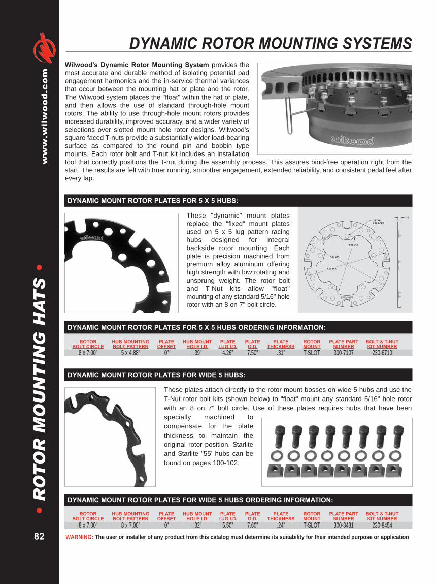
WARNING: The user or installer of any product from this catalog must determine its suitability for their intended purpose or application
www.wilwood.com
82
•R
OT
OR
MO
UN
TIN
GH
AT
S•
DYNAMIC ROTOR MOUNTING SYSTEMSWilwood's Dynamic Rotor Mounting System provides themost accurate and durable method of isolating potential padengagement harmonics and the in-service thermal variancesthat occur between the mounting hat or plate and the rotor.The Wilwood system places the "float" within the hat or plate,and then allows the use of standard through-hole mountrotors. The ability to use through-hole mount rotors providesincreased durability, improved accuracy, and a wider variety ofselections over slotted mount hole rotor designs. Wilwood'ssquare faced T-nuts provide a substantially wider load-bearingsurface as compared to the round pin and bobbin typemounts. Each rotor bolt and T-nut kit includes an installationtool that correctly positions the T-nut during the assembly process. This assures bind-free operation right from thestart. The results are felt with truer running, smoother engagement, extended reliability, and consistent pedal feel afterevery lap.
These "dynamic" mount platesreplace the "fixed" mount platesused on 5 x 5 lug pattern racinghubs designed for integralbackside rotor mounting. Eachplate is precision machined frompremium alloy aluminum offeringhigh strength with low rotating andunsprung weight. The rotor boltand T-Nut kits allow "float"mounting of any standard 5/16" holerotor with an 8 on 7" bolt circle.
.31.39 DIA5 PLACES
4.88 DIA
7.50 DIA
7.00 DIA
DYNAMIC MOUNT ROTOR PLATES FOR 5 X 5 HUBS:
These plates attach directly to the rotor mount bosses on wide 5 hubs and use theT-Nut rotor bolt kits (shown below) to "float" mount any standard 5/16" hole rotorwith an 8 on 7" bolt circle. Use of these plates requires hubs that have beenspecially machined tocompensate for the platethickness to maintain theoriginal rotor position. Starliteand Starlite "55' hubs can befound on pages 100-102.
DYNAMIC MOUNT ROTOR PLATES FOR WIDE 5 HUBS:
ROTOR HUB MOUNTING PLATE HUB MOUNT PLATE PLATE PLATE ROTOR PLATE PART BOLT & T-NUTBOLT CIRCLE BOLT PATTERN OFFSET HOLE I.D. LUG I.D. O.D. THICKNESS MOUNT NUMBER KIT NUMBER8 x 7.00” 5 x 4.88” 0” .39” 4.26” 7.50” .31” T-SLOT 300-7107 230-6710
DYNAMIC MOUNT ROTOR PLATES FOR 5 X 5 HUBS ORDERING INFORMATION:
ROTOR HUB MOUNTING PLATE HUB MOUNT PLATE PLATE PLATE ROTOR PLATE PART BOLT & T-NUTBOLT CIRCLE BOLT PATTERN OFFSET HOLE I.D. LUG I.D. O.D. THICKNESS MOUNT NUMBER KIT NUMBER8 x 7.00” 8 x 7.00” 0” .32” 5.50” 7.60” .24” T-SLOT 300-8431 230-8454
DYNAMIC MOUNT ROTOR PLATES FOR WIDE 5 HUBS ORDERING INFORMATION:
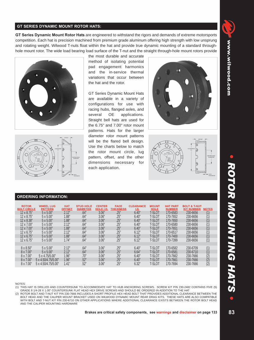
Brakes are critical safety components, see warnings and disclaimer on page 133
www.wilw
ood.com
83
•R
OT
OR
MO
UN
TIN
GH
AT
S•
GT SERIES DYNAMIC MOUNT ROTOR HATS:
GT Series Dynamic Mount Rotor Hats are engineered to withstand the rigors and demands of extreme motorsportscompetition. Each hat is precision machined from premium grade aluminum offering high strength with low unsprungand rotating weight. Wilwood T-nuts float within the hat and provide true dynamic mounting of a standard through-hole mount rotor. The wide load bearing load surface of the T-nut and the straight through-hole mount rotors provide
the most durable and accuratemethod of isolating potentialpad engagement harmonicsand the in-service thermalvariations that occur betweenthe hat and the rotor.
GT Series Dynamic Mount Hatsare available in a variety ofconfigurations for use withracing hubs, flanged axles, andseveral OE applications.Straight bell hats are used forthe 6.75" and 7.00" rotor mountpatterns. Hats for the largerdiameter rotor mount patternswill be the flared bell design.Use the charts below to matchthe rotor mount circle, lugpattern, offset, and the otherdimensions necessary foreach application.
CLEARANCE
I.D.
DISC
BOLT
CIRCLE
STUD
BOLT CIRCLE
OFFSET
FACE
THICKNESS
CENTER HOLE
DIAMETER
CLEARANCE
I.D.
STUD
BOLT CIRCLE
DISC
BOLT
CIRCLE
OFFSET
FACE
THICKNESS
CENTER HOLE
DIAMETER
NOTES:(1) THIS HAT IS DRILLED AND COUNTERSUNK TO ACCOMMODATE HAT TO HUB ANCHORING SCREWS. SCREW KIT P/N 230-2482 CONTAINS FIVE (5)
GRADE 8 1/4-28 X 1.00” COUNTERSUNK FLAT HEAD HEX DRIVE SCREWS AND SHOULD BE ORDERED IN ADDITION TO THE HAT(2) ROTOR BOLT AND T-NUT KIT P/N 230-7666 INCLUDES A SHORT PROFILE HEX HEAD BOLT THAT PROVIDES ADDITIONAL CLEARANCE BETWEEN THE
BOLT HEAD AND THE CALIPER MOUNT BRACKET USED ON WILWOOD DYNAMIC MOUNT REAR DRAG KITS. THESE HATS ARE ALSO COMPATIBLEWITH BOLT AND T-NUT KIT P/N 230-6710 ON OTHER APPLICATIONS WHERE ADDITIONAL CLEARANCE EXISTS BETWEEN THE ROTOR BOLT HEADAND THE CALIPER MOUNTING HARDWARE
ROTOR WHEEL LUG HAT STUD HOLE CENTER FACE CLEARANCE MOUNT HAT PART BOLT & T-NUTBOLT CIRCLE PATTERN OFFSET DIAMETER HOLE I.D. THICKNESS I.D. HOLE NUMBER KIT NUMBER NOTES12 x 8.75” 5 x 5.00” 2.12” .64” 3.06” .25” 6.40” T-SLOT 170-6583 230-6656 (1)12 x 8.75” 5 x 5.00” 1.88” .64” 3.06” .25” 6.40” T-SLOT 170-7652 230-6656 (1)12 x 8.38” 5 x 5.00” 1.88” .64” 3.06” .25” 6.40” T-SLOT 170-7650 230-6656 (1)12 x 7.00” 5 x 5.00” 2.12” .64” 3.06” .25” 6.40” T-SLOT 170-6580 230-6656 (1)12 x 7.00” 5 x 5.00” 1.88” .64” 3.06” .25” 6.40” T-SLOT 170-7651 230-6656 (1)12 x 6.75” 5 x 5.00” 2.12” .64” 3.06” .25” 6.12” T-SLOT 170-6517 230-6656 (1)12 x 6.75” 5 x 5.00” 1.88” .64” 3.06” .25” 6.12” T-SLOT 170-7400 230-6656 (1)12 x 6.75” 5 x 5.00” 1.74” .64” 3.06” .25” 6.12” T-SLOT 170-7399 230-6656 (1)
8 x 8.50” 5 x 5.00” 2.12” .64” 3.06” .25” 6.40” T-SLOT 170-6582 230-6709 (1)8 x 7.00” 5 x 5.00” 2.12” .64” 3.06” .25” 6.64” T-SLOT 170-6581 230-6710 (1)8 x 7.00” 5 x 4.75/5.00” 1.96” .70” 3.06” .25” 6.40” T-SLOT 170-7662 230-7666 (2)8 x 7.00” 5 x 4.50/4.75/5.00” 1.96” .52” 3.06” .25” 6.40” T-SLOT 170-7661 230-7666 (2)8 x 7.00” 5 x 4.50/4.75/5.00” 1.41” .52” 3.06” .25” 6.32” T-SLOT 170-7694 230-7666 (2)
ORDERING INFORMATION:

WARNING: The user or installer of any product from this catalog must determine its suitability for their intended purpose or application
www.wilwood.com
84
•R
OT
OR
MO
UN
TIN
GH
AT
S•
FIXED MOUNT ROTOR HATSGT Series Fixed Mount Rotor HatsGT Series hats are precision machined from premium aluminum alloys for high strength and attention to minimizedweight. Hats in this category feature threaded rotor mount holes for use with standard through-hole mount rotors.Threaded hole hats may also be used with T-Nuts or bobbins designed for use with specially machined slotted holedynamic mount rotors. When used in conjunction with matched Wilwood rotor hardware kits, GT hats provide solid,reliable performance in the most demanding conditions.
ROTOR BOLT
CIRCLE
STUD BOLT
CIRCLE
MOUNTING HOLE
CENTER HOLE
DIAMETER
CLEARANCE
I.D.
OFFSETFACE
THICKNESS
Shallow Offset Hats are for narrowspace applications with offsets oftenless than 1.00". They are availablefor most rotor bolt patterns in avariety of four and five lug wheelpatterns.
SHALLOW OFFSET HATS:
OFFSET
FACE THICKNESS
CENTER
HOLE
DIA
CLEARANCE
I.D.
MOUNTING
HOLE
STUD
BOLT CIRCLE
DISC
BOLT CIRCLE
Straight Bell Hats are most oftenused with 11.75" to 13.00" diameterrotors with 6.75" or 7.00" rotor mountbolt circle rotors on stock car fronthubs and rear axles.
STRAIGHT BELL HATS:
ROTOR BOLT
CIRCLE
STUD BOLT
CIRCLE
CLEARANCE
I.D.
MOUNTING HOLE OFFSET
CENTER HOLE
DIAMETER
FACE
THICKNESS
Flared Bell Hats are generally usedwith rotor mount bolt circles of 8.38"and larger. Offsets range from 1.88"to 3.00" for rotor diameters 12.19"and up.
FLARED BELL HATS:
CLEARANCE
I.D.
ROTOR
BOLT CIRCLE
MOUNTING HOLE OFFSET FACE
THICKNESS
STUD BOLT
CIRCLE
CENTER HOLE
DIAMETER
Truck Hats feature strengtheningribs on a flared bell configuration forbig rotor brake kits on truck, SUV,and 4WD axles with either 6 or 8 lugconfigurations.
TRUCK HATS:

Brakes are critical safety components, see warnings and disclaimer on page 133
www.wilw
ood.com
85
•R
OT
OR
MO
UN
TIN
GH
AT
S•
GT SERIES FIXED MOUNT ROTOR HATS:GT Series Fixed Mount Rotor Hats are available in a variety of configurations for use with racing hubs, flanged axles, and several OEapplications. Use the chart below to match the rotor mount circle, lug pattern, offset, and other dimensions necessary for each application.
NOTES: (1) THIS HAT IS DRILLED AND COUNTERSUNK TO ACCOMMODATE HAT TO HUB ANCHORING SCREWS. SCREW KIT P/N 230-2482 CONTAINS FIVE (5) GRADE 81/4-28 X 1.00” COUNTERSUNK FLAT HEAD HEX DRIVE SCREWS AND SHOULD BE ORDERED IN ADDITION TO THE HAT
(2) OFFSET DIMENSION INCLUDES .100” THICKNESS FROM STAINLESS STEEL INSULATOR SPACERS SUPPLIED WITH ROTOR BOLT KIT P/N 230-3319(3).48” / .52” DUAL PATTERN 5 X 4.50 STUD HOLE SIZES
ROTOR WHEEL LUG HAT STUD HOLE CENTER FACE CLEARANCE MOUNT HAT PART ROTOR BOLTBOLT CIRCLE PATTERN OFFSET DIAMETER HOLE I.D. THICKNESS I.D. HOLE NUMBER KIT NUMBER NOTES12 x 10.75” 8 x 6.50” 1.55” .63” 4.64” .45” 7.85” 5/16-18 170-8878 230-906812 x 10.75” 6 x 5.50” .813” .63” 3.09” .45” 7.21” 5/16-18 170-8960 230-906812 x 10.75” 6 x 5.32” 1.11” .59” 3.42” .25” 7.05” 5.16-18 170-9066 230-906812 x 9.18” 6 x 5.50” .813” .63” 3.09” .45” 8.14” 1/4-20 170-9891 230-821712 x 9.18” 5 x 4.75” 0.41” .52” 2.78” .30” 8.14” 1/4-20 170-8073 230-457212 x 9.18” 5 x 4.75 0.29” .52” 2.78” .30” 8.14” 1/4-20 170-8920 230-457212 x 8.75” 6 x 5.50” 0.99” .58” 3.97” .38” 7.37” 1/4-20 170-9523 230-457212 x 8.75” 5 x 5.00” 2.25” .64” 3.06” .25” 6.40” 1/4-20 170-4568 230-4572 (1)12 x 8.75” 5 x 5.00” 2.12” .64” 3.06” .25” 6.40” 1/4-20 170-4844 230-4572 (1)12 x 8.75” 5 x 5.00” 1.50” .64” 3.06” .25” 6.40” 1/4-20 170-5429 230-4572 (1)12 x 8.75” 5 x 4.50/4.75” 1.20” .52” 3.00” .25” 6.93” 1/4-20 170-8883 230-457212 x 8.75” 5 x 4.75” 1.62” .52” 3.06” .25” 6.85” 1/4-20 170-10753 230-800812 x 8.75” 5 x 4.75” 0.88” .52” 2.78” .30” 7.13” 1/4-20 170-6837 230-457212 x 8.75” 5 x 4.75” 0.71” .52” 2.78” .31” 7.49” 1/4-20 170-10533 230-457212 X 8.75” 5 x 4.75” 0.56” .52” 3.12” .29” 7.75” 1/4-20 170-8815 230-457212 x 8.75” 5 x 4.75” 0.41” .52” 2.78” .30” 7.72” 1/4-20 170-8132 230-457212 x 8.75” 5 x 4.75” 0.29” .52” 2.78” .30” 7.73” 1/4-20 170-8919 230-457212 x 8.75” 5 x 4.72/4.50” 1.00” .67” 2.82” .39” 7.75” 1/4-20 170-8757 230-457212 x 8.75” 5 x 4.50/4.75” 2.00” .52” 3.06” .25” 6.40” 1/4-20 170-7038 230-457212 x 8.75” 5 x 4.50/4.75” 1.88” .52” 3.06” .25” 6.40” 1/4-20 170-6994 230-457212 x 8.75” 5 x 4.50/4.75” 1.75” .52” 3.06” .25” 6.40” 1/4-20 170-7467 230-457212 x 8.75” 5 x 4.50/4.75” 1.20” .52” 3.06” .25” 7.25” 1/4-20 170-10231 230-457212 x 8.75” 5 x 4.50” 0.81” .52” 3.06” .25” 7.25” 1/4-20 170-6126 230-457212 x 8.75” 5 x 4.50” 0.75” .52” 2.69” .38” 7.25” 1/4-20 170-9294 230-457212 x 8.75” 5 x 4.50” 0.64” .58” 2.80” .31” 6.30” 1/4-20 170-9128 230-457212 x 8.75” 5 x 4.50” 0.54” .52” 2.77” .25” 7.25” 1/4-20 170-10294 230-457212 x 8.75” 5 x 4.50” 0.54” .52” 2.69” .38” 7.25” 1/4-20 170-9289 230-457212 x 8.75” 5 x 4.50” 0.54” .52” 2.53” .25” 7.25” 1/4-20 170-10295 230-457212 x 8.75” 5 x 4.50” 0.54” .52” 2.44” .25” 7.45” 1/4-20 170-10761 230-457212 x 8.75” 5 x 4.50” 0.41” .58” 2.80” .27” 7.75” 1/4-20 170-6223 230-457212 x 8.75” 5 x 4.50” 0.21” .52” 2.72” .25” 8.01” 1/4-20 170-9558 230-457212 x 8.75” 5 x 3.94” 1.10” .52” 2.29” .27” 7.02” 1/4-20 170-6990 230-457212 x 8.75” 5 x 3.93” 0.71” .52” 2.17” .30” 7.49” 1/4-20 170-9011 230-457212 x 8.75” 4 x 4.25” 0.81” .52” 3.06” .25” 7.25” 1/4-20 170-6157 230-457212 x 8.75” 4 x 3.93” 0.55” .52” 2.17” .25” 7.49” 1/4-20 170-8357 230-457212 x 8.38” 5 x 5.00” 1.88” .64” 3.06” .25” 6.40” 1/4-20 170-5260 230-4572 (1)12 x 7.06” 5 x 4.75” 0.25” .52” 2.78” .30” 6.18” 1/4-20 170-7746 230-800812 x 7.00” 5 x 5.00” 2.12” .64” 3.06” .25” 6.40” 1/4-20 170-4847 230-4572 (1)12 x 7.00” 5 x 4.75” 0.81” .52” 2.78” .30” 6.00” 1/4-20 170-8492 230-457212 x 7.00” 5 x 4.50/4.75” 2.01” .54” 2.66” .25” 5.93” 1/4-20 170-9321 230-457212 x 7.00” 5 x 4.50” 0.35” .58” 2.80” .27” 6.19” 1/4-20 170-8588 230-800812 x 7.00” 5 x 4.50” 0.21” .52” 2.72” .25” 6.22” 1/4-20 170-8750 230-800812 x 6.75” 5 x 4.75” 0.75” .52” 3.11” .29” 5.84” 1/4-20 170-8687 230-80088 x 8.50” 5 x 5.00” 2.50” .64” 3.06” .25” 6.40” 1/4-20 170-5588 230-4572 (1)8 x 7.00” 5 x 5.00” 2.50” .64” 3.06” .25” 6.64” 5/16-18 170-2751 230-2589 (1)8 x 7.00” 5 x 5.00” 2.12” .64” 3.06” .25” 6.64” 5/16-18 170-2522 230-2589 (1)8 x 7.00” 5 x 4.75” 0.88” .52” 2.78” .30” 6.00” 5/16-18 170-8493 230-83908 x 7.00” 5 x 4.50/4.75” 1.43” .52” 3.00” .25” 6.04” 5/16-18 170-7632 230-34848 x 7.00” 5 x 4.50” 1.59” .52” 2.78” .25” 6.04” 5/16-18 170-10782 230-05628 x 7.00” 5 x 4.50” 1.23” .58” 2.80” .25” 7.90 5/16-18 170-10041 230-83908 x 7.00” 5 x 4.50” 1.05” .58” 2.78” .28” 6.02” 5/16-18 170-8589 230-83908 x 7.00” 5 x 4.50” 0.94” .48/.52” 2.66” .24” 5.90” 5/16-18 170-8320 230-8390 (3)8 x 7.00” 5 x 4.50” 0.75” .50” 2.80” .25” 7.90” 5/16-18 170-10040 230-83908 x 7.00” 5 x 4.50” 0.72” .50” 2.53” .25” 5.90” 5/16-18 170-6947 230-83908 x 7.00” 5 x 4.50” 0.65” .58” 2.80” .25” 5.90” 5/16-18 170-10690 230-83908 x 7.00” 5 x 4.38” 1.01” .45” 3.25” .25” 5.88” 5/16-18 170-8386 230-83908 x 7.00” 5 x 3.94” 1.09” .52” 2.28” .27” 5.27” 5/16-18 170-9206 230-83908 x 7.00” 5 x 3.93” 0.77” .50” 2.30” .32” 5.90” 5/16-18 170-8324 230-83908 x 7.00” 5 x 3.93” 0.50” .55” 2.40” .25” 5.90” 5/16-18 170-6378 230-83908 x 7.00” 5 x 3.93” 0.41” .58” 2.56” .25” 5.90” 5/16-18 170-8269 230-83908 x 7.00” 4 x 4.50” 0.72” .50” 2.72” .25” 5.90” 5/16-18 170-6996 230-83908 x 7.00” 4 x 3.93” 1.16” .50” 2.53” .25” 5.90” 5/16-18 170-8405 230-83908 x 7.00” 4 x 3.93” 0.83” .64” 2.53” .26” 5.90” 5/16-18 170-10650 230-83908 x 7.00” 4 x 3.93” 0.83” .52” 2.53” .26” 5.90” 5/16-18 170-8645 230-83908 x 7.00” 4 x 3.93” 0.75” .50” 2.41” .32” 5.90” 5/16-18 170-10200 230-83908 x 7.00” 4 x 3.93” 0.45” .50” 2.53” .25” 5.90” 5/16-18 170-6288 230-83908 x 7.00” Undrilled 1.22” N/A 2.17” .26” 6.40” 5/16-18 171-8976 230-83908 x 7.00” Undrilled 0.72” N/A 2.40” .25” 5.90” 5/16-18 171-7671 230-83906 x 6.25” 4 x 3.93” 0.75” .50” 2.41” .32” 5.20” 5/16-18 170-10199 230-89916 x 6.25” 4 x 3.93” 0.66” .50” 2.53” .32” 5.60” 5/16-18 170-8643 230-89916 x 6.25” Undrilled 0.77” N/A 2.17” .32” 5.60” 5/16-18 171-8975 230-8991
ORDERING INFORMATION:

WARNING: The user or installer of any product from this catalog must determine its suitability for their intended purpose or application
www.wilwood.com
86
•R
OT
OR
MO
UN
TIN
GH
AT
S•
FIXED MOUNT ROTOR MOUNTING HATS
NOTES:(1) ROTOR BOLT KIT P/N 230-0233D INCLUDES A SHORT PROFILE HEX HEAD BOLT THAT PROVIDES ADDITIONAL CLEARANCE BETWEEN THE BOLT HEAD &
THE CALIPER MOUNTING HARDWARE AS USED IN WILWOOD LIGHTWEIGHT READ DRAG KITS. THESE HATS CAN ALSO BE USED WITH BOLT KIT P/N230-2589, OTHER APPLICATIONS WHERE ADDITIONAL CLEARANCE EXISTS BETWEEN THE ROTOR BOLT HEAD & THE CALIPER MOUNT HARDWARE
(2) THIS HAT IS UN-ANODIZED
ROTOR WHEEL LUG HAT STUD HOLE CENTER FACE CLEARANCE MOUNT HAT PART ROTOR BOLTBOLT CIRCLE PATTERN OFFSET DIAMETER HOLE I.D. THICKNESS I.D. HOLE NUMBER KIT NUMBER NOTES
8 x 7.62” 6 x 5.00” 2.00” .64” 3.50” .25” 6.50” .323” 170-0089 230-01508 x 7.62” 5 x 4.50/4.75/5.00” 2.00” .52” 3.06” .25” 6.50” .323” 170-1827 230-0150 (2)8 x 7.62” 5 x 4.75” 1.50” .51” 2.85” .50” 6.51” .323” 170-0176 230-01508 x 7.62” 5 x 4.50” 2.10” .50” 2.75” .25” 6.31” .323” 170-0636 230-01508 x 7.62” 5 x 4.50” 1.38” .67” 3.23” .25” 6.27” .323” 170-0635 230-01508 x 7.62” 5 x 4.50” 1.25” .52” 3.06” .25” 6.32” .323” 170-3265 230-01508 x 7.62” 4 x 4.25” 2.00” .52” 3.06” .29” 6.50” .323” 170-2637 230-01508 x 7.62” 4 x 4.25” 1.25” .52” 3.06” .29” 6.32” .323” 170-3149 230-01508 x 7.62” Undrilled 2.00” — 2.78” .25” 6.50” .323” 171-2233 230-0150
ROTOR WHEEL LUG HAT STUD HOLE CENTER FACE CLEARANCE MOUNT HAT PART ROTOR BOLTBOLT CIRCLE PATTERN OFFSET DIAMETER HOLE I.D. THICKNESS I.D. HOLE NUMBER KIT NUMBER NOTES
8 x 7.00” 5 x 4.75/5.00” 1.96” .70” 3.06” .25” 6.14” 5/16-18 170-5244 230-0233D (1)8 x 7.00” 5 x 4.50/4.75/5.00” 1.96” .52” 3.06” .25” 6.14” 5/16-18 170-0208 230-0233D (1)8 x 7.00” 5 x 4.50/4.75/5.00” 1.77” .52” 3.06” .25” 6.14” 5/16-18 170-0357 230-0233D (1)8 x 7.00” 5 x 4.50/4.75/5.00” 1.71” .52” 3.06” .25” 6.14” 5/16-18 170-0259 230-0233D (1)8 x 7.00” 5 x 4.50/4.75/5.00” 1.59” .52” 3.06” .25” 6.14” 5/16-18 170-0317 230-0233D (1)8 x 7.00” 5 x 4.50/4.75/5.00” 1.41” .52” 3.06” .50” 6.14” 5/16-18 170-0764 230-0233D (1)8 x 7.00” Undrilled 1.96” — 3.06” .25” 6.14” 5/16-18 171-3753 230-0233D (1)8 x 7.00” Undrilled 1.71” — 3.06” .25” 6.14” 5/16-18 171-3754 230-0233D (1)8 x 7.00” Undrilled 1.59” — 3.06” .25” 6.14” 5/16-18 171-3755 230-0233D (1)8 x 7.00” Undrilled 1.41” — 2.78” .50” 6.14” 5/16-18 171-2234 230-0233D (1)
HD FIXED MOUNT ALUMINUM HATS FOR 5/16-24 THREADED HOLE ROTORS ORDERING INFORMATION:
HD FIXED MOUNT ALUMINUM HATS FOR 5/16’ THROUGH-HOLE ROTORS ORDERING INFORMATION:
Wilwood's HD Series Fixed Mount Rotor Hats have a long standing reputation for fit, performance, and durability.HD Series hats are manufactured from premium grade aluminum alloys offering high strength, low weight, and showquality appeal. HD hats have not only been a mainstay in many of Wilwood's racing disc brake conversion kits, butthey can cover a range of applications from an OE four lug axle shaft to a Grand-National stock car racing hub. HDhats feature a straight bell construction with a flanged rotor mount ring. These features combine to provide maximumradial clearance between the caliper body and the hat. This can be a critical factor when trying to squeeze a largecaliper inside a small wheel. Many hats offer multi-lug wheel patterns for added versatility. Some hats can be orderedblank for custom axle building and other unique applications.
The HD hat configurations aredivided into two groups. Thereare threaded hole hats for usewith though-hole mount rotors,and there are through-holemount hats for use with threadedhole rotors. When used withmatching Wilwood rotorhardware, these hats providesolid mounting for a wide rangeof custom and competition discbrake applications. Use thecharts below to match the rotormount, lug pattern, offset, andthe other dimensions necessaryfor each application.
CLEARANCE
I.D.
OFFSET
FACE
THICKNESS
DISC BOLT
CIRCLE
STUD BOLT
CIRCLE
MOUNTING HOLE
CENTER HOLE
DIAMETER
HD SERIES FIXED MOUNT ROTOR HATS:

ORDERING INFORMATION:
These premium grade cast iron hats make itpossible to use bolt-on rotors on vehiclesequipped with internal shoe parking brakeassemblies. Each hat is a precisionmachined, threaded hole design for use inconjunction with through-hole mount rotors.After machining, the hats are zinc plated forcorrosion resistance. Use the charts belowto match the rotor mount circle, lug pattern,offset, and other dimensions necessary foreach application.
CLEARANCE
I.D.
OFFSET
FACE
THICKNESS
DISC BOLT
CIRCLE
STUD BOLT
CIRCLE
MOUNTING HOLE
CENTER HOLE
DIAMETER
ROTOR WHEEL LUG HAT STUD HOLE CENTER FACE CLEARANCE MOUNT HAT PART ROTOR BOLTBOLT CIRCLE PATTERN OFFSET DIAMETER HOLE I.D. THICKNESS I.D. HOLE NUMBER KIT NUMBER NOTES
12 x 10.75” 8 x 6.50” 1.91” .64” 4.83” .39” 7.87” 5/16-24 170-9607 230-958712 x 10.75” 8 x 6.50” 1.78” .64” 4.63” .32” 7.87” 5/16-24 170-9608 230-958712 x 9.18” 6 x 5.50” 2.34” .63” 3.09” .24” 7.29” 1/4-28 170-9890 230-821712 x 8.75” 5 x 4.50/4.75/5.00” 1.95” .52” 2.78” .18” 6.85” 1/4-28 170-9493 230-821712 x 8.75” 5 x 4.50/4.75/5.00” 1.54” .52” 2.70” .18” 6.85” 1/4-28 170-9492 230-821712 X 8.75” 5 X 5.00” 1.54” .52” 3.12” .18” 6.85” 1/4-28 170-9984 230-821712 x 8.75” 5 x 4.75” 1.32” .52” 2.78” .25” 6.47” 1/4-28 170-9839 230-821712 x 8.75” 5 x 4.75” 0.69” .52” 2.78” .25” 7.10” 1/4-28 170-8169 230-821712 x 8.75” 5 x 4.50” 2.16” .51” 2.69” .20” 6.65” 1/4-28 170-9455 230-821712 x 8.75” 5 x 4.50” 1.32” .51” 3.54” .20” 6.11” 1/4-28 170-9599 230-8217
8 x 7.78” 5 x 4.50/4.75/5.00” 2.39” .52” 3.06” .18” 6.63” 1/4-28 170-6239 230-64098 X 7.78” 5 X 3.93” 1.64” .51” 2.29” .26” 5.76” 1/4-28 170-10108 230-7011
ROTOR WHEEL LUG HAT STUD HOLE CENTER FACE CLEARANCE MOUNT HAT PART ROTOR BOLTBOLT CIRCLE PATTERN OFFSET DIAMETER HOLE I.D. THICKNESS I.D. HOLE NUMBER KIT NUMBER NOTES
8 x 7.00” 5 x 4.50/4.75/5.00” 3.02” .52” 3.06” .09” 5.83” .325” 170-3695 230-0840
Brakes are critical safety components, see warnings and disclaimer on page 133
www.wilw
ood.com
Lightweight and strong, these clamps provides sturdy fixed position mountingfor rear inboard brake systems on live axle sprints and modifieds.
87
•R
OT
OR
MO
UN
TIN
GH
AT
S•
FIXED MOUNT IRON HATS FOR INTERNAL SHOW PARKING BRAKES AND BOLT-ON ROTORS:
ORDERING INFORMATION:
SPRINT - OPEN WHEEL LIVE AXLE CLAMP-ON ROTOR MOUNT:
These lightweight, high-strength spunsteel hats provide solid mounting of bolt-onrotors to OE axles and racing hubs whenaluminum hats are not allowed. Each hatfeatures a multi-hole lug pattern foruniversal application on the popular 5 lugmount patterns. These hats are not foruse on parking brake applications.
CLEARANCE
I.D.
OFFSET
FACE
THICKNESS
DISC BOLT
CIRCLE
STUD BOLT
CIRCLE
MOUNTING HOLE
CENTER HOLE
DIAMETER
FIXED MOUNT SPUN STEEL HATS FOR BOLT-ON ROTORS:
NOTES: (1) USE BOLT KIT P/N 230-2404 WITH VENTED IRON AND OTHER 5/16” THROUGH-HOLE FIXED MOUNT ROTORS(2) USE BOLT AND T-NUT KIT P/N 230-5567 WITH DYNAMIC MOUNT LIGHTWEIGHT STEEL T-SLOTTED ROTORS(3) DYNAMIC MOUNT BOLT KIT INCLUDED(4) MAGNESIUM CLAMP
ROTOR AXLE ROTOR AXLE CLAMP ROTOR BOLTBOLT CIRCLE SPLINE MOUNT HOLE PART NUMBER KIT NUMBER8 x 7.00” 3.00” x 46 Spline 5/16” 270-2394 (1, 2, 4)8 x 7.00” 3.00” x 46 Spline 5/16” 270-10484 (3)6 x 5.50” 3.00” x 46 Spline 5/16” 270-9761 (3)
ORDERING INFORMATION:

WARNING: The user or installer of any product from this catalog must determine its suitability for their intended purpose or application
www.wilwood.com
88
•R
AC
ING
HU
BS
•STARLITE “55” WIDE 5 RACING HUBS
Hub Features:Starlite "55" hubs provide the superior strength of permanent mold, high densityaircraft aluminum at weights comparable to the much higher priced magnesiumhub assemblies. The Starlite "55" features the strength of our traditional eightbolt Starlite hub, but with a redesign focussed on eliminating unnecessaryweight in the hub and its related components.
Rear hubs have been reconfigured to include five bolt drive flanges and weighin at less than 7 pounds with bearing races and studs installed. When combinedwith the additional weight savings of the five bolt drive flange and bolt kit, theassembled hub meets or beats the assembled weight of nearly every eight boltmagnesium hub assembly available.
Front hubs offer further weightreduction by completely eliminatingthe bolt bosses with the use of afiber reinforced composite Snap-Capdust cover. Optional drilled studsround-out the total lightweightpackage. Starlite "55" hubs areavailable in the traditional GM orstandard rotor mount offset, with anall new configuration available foruse with Wilwood's dynamic rotormount plates. Standard offset hubscan be ordered with a special blackcoating that seals the surface andmaintains a clean appearanceagainst oxidation and corrosion fromtrack born substances.
STARLITE “55” FIVE BOLT DRIVE REAR HUBS ORDERING INFORMATION:
OFFSET FINISH STUDS PART NUMBERStandard Aluminum 5/8” Coarse 270-6513CStandard Aluminum 5/8” Coarse Drilled 270-6513DStandard Black 5/8” Coarse 270-6513BCStandard Black 5/8” Coarse Drilled 270-6513BDGM Aluminum 5/8” Coarse 270-6514CGM Aluminum 5/8” Coarse Drilled 270-6514DDynamic Mount Aluminum 5/8” Coarse 270-8435CDynamic Mount Aluminum 5/8” Coarse Drilled 270-8435D
STARLITE “55” FRONT HUBS WITH SNAP-CAP ORDERING INFORMATION:
OFFSET FINISH STUDS PART NUMBERStandard Aluminum 5/8” Coarse 270-6735CStandard Aluminum 5/8” Coarse Drilled 270-6735DStandard Black 5/8” Coarse 270-6735BCStandard Black 5/8” Coarse Drilled 270-6735BDGM Aluminum 5/8” Coarse 270-6736CGM Aluminum 5/8” Coarse Drilled 270-6736DDynamic Mount Aluminum 5/8” Coarse 270-8436CDynamic Mount Aluminum 5/8” Coarse Drilled 270-8436D
OFFSET
WHEEL STUD
7/16-14 THREAD
5 PLACES ON A
3.98 (101,1) DIA
BOLT CIRCLE
DESCRIPTION
STANDARD (P/N 270-6513)
GM (P/N 270-6514)
DYNAMIC ROTOR MOUNT
OFFSET
3.57 (90,7)
3.45 (87,6)
3.32 (84,3)
2.65 (67,3) Starlite “55” Rear Wide 5Racing Hub
Starlite “55” Front Hubwith Snap-Cap
Starlite “55” Hub Offset Diagram
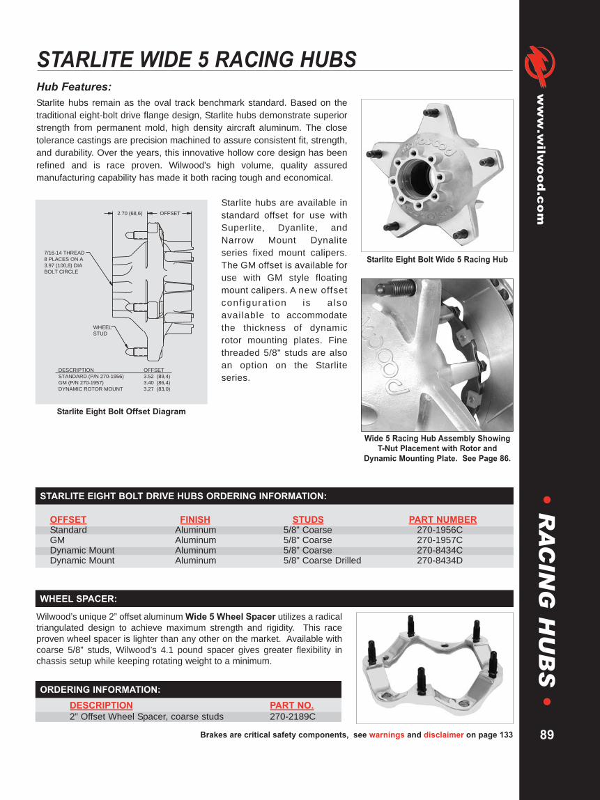
Brakes are critical safety components, see warnings and disclaimer on page 133
www.wilw
ood.com
•R
AC
ING
HU
BS
•Hub Features:Starlite hubs remain as the oval track benchmark standard. Based on thetraditional eight-bolt drive flange design, Starlite hubs demonstrate superiorstrength from permanent mold, high density aircraft aluminum. The closetolerance castings are precision machined to assure consistent fit, strength,and durability. Over the years, this innovative hollow core design has beenrefined and is race proven. Wilwood's high volume, quality assuredmanufacturing capability has made it both racing tough and economical.
Starlite hubs are available instandard offset for use withSuperlite, Dyanlite, andNarrow Mount Dynaliteseries fixed mount calipers.The GM offset is available foruse with GM style floatingmount calipers. A new offsetconf igurat ion is alsoavailable to accommodatethe thickness of dynamicrotor mounting plates. Finethreaded 5/8" studs are alsoan option on the Starliteseries.
STARLITE WIDE 5 RACING HUBS
STARLITE EIGHT BOLT DRIVE HUBS ORDERING INFORMATION:
OFFSET FINISH STUDS PART NUMBERStandard Aluminum 5/8” Coarse 270-1956CGM Aluminum 5/8” Coarse 270-1957CDynamic Mount Aluminum 5/8” Coarse 270-8434CDynamic Mount Aluminum 5/8” Coarse Drilled 270-8434D
Wilwood’s unique 2” offset aluminum Wide 5 Wheel Spacer utilizes a radicaltriangulated design to achieve maximum strength and rigidity. This raceproven wheel spacer is lighter than any other on the market. Available withcoarse 5/8” studs, Wilwood’s 4.1 pound spacer gives greater flexibility inchassis setup while keeping rotating weight to a minimum.
DESCRIPTION PART NO.2” Offset Wheel Spacer, coarse studs 270-2189C
WHEEL SPACER:
ORDERING INFORMATION:
89
Wide 5 Racing Hub Assembly ShowingT-Nut Placement with Rotor and
Dynamic Mounting Plate. See Page 86.
Starlite Eight Bolt Wide 5 Racing Hub
OFFSET
WHEEL
STUD
7/16-14 THREAD
8 PLACES ON A
3.97 (100,8) DIA
BOLT CIRCLE
2.70 (68,6)
DESCRIPTION
STANDARD (P/N 270-1956)
GM (P/N 270-1957)
DYNAMIC ROTOR MOUNT
OFFSET
3.52 (89,4)
3.40 (86,4)
3.27 (83,0)
Starlite Eight Bolt Offset Diagram
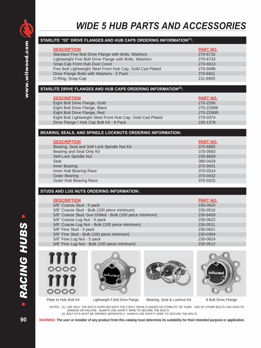
WARNING: The user or installer of any product from this catalog must determine its suitability for their intended purpose or application
www.wilwood.com
90
•R
AC
ING
HU
BS
•WIDE 5 HUB PARTS AND ACCESSORIES
DESCRIPTION PART NO.Bearing, Seal and Self Lock Spindle Nut Kit 370-6885Bearing and Seal Only Kit 370-0563Self-Lock Spindle Nut 230-6659Seal 380-0429Inner Bearing 370-0431Inner Hub Bearing Race 370-0314Outer Bearing 370-0432Outer Hub Bearing Race 370-0315
BEARING, SEALS, AND SPINDLE LOCKNUTS ORDERING INFORMATION:
DESCRIPTION PART NO.5/8" Coarse Stud - 5 pack 230-06205/8" Coarse Stud - Bulk (100 piece minimum) 230-05105/8” Coarse Stud, Gun Drilled - Bulk (100 piece minimum) 230-64595/8" Coarse Lug Nut - 5 pack 230-06225/8" Coarse Lug Nut - Bulk (100 piece minimum) 230-05115/8" Fine Stud - 5 pack 230-06215/8" Fine Stud - Bulk (100 piece minimum) 230-03045/8" Fine Lug Nut - 5 pack 230-06245/8" Fine Lug Nut - Bulk (100 piece minimum) 230-0512
STUDS AND LUG NUTS ORDERING INFORMATION:
Plate to Hub Bolt Kit Lightweight 5 Bolt Drive Flange 8 Bolt Drive FlangeBearing, Seal & Locknut Kit
NOTES: (1) USE ONLY THE BOLTS SUPPLIED WITH THE 5 BOLT DRIVE FLANGES ON STARLITE “55” HUBS. USE OF OTHER BOLTS CAN LEAD TODAMAGE OR FAILURE. ALWAYS USE SAFETY WIRE TO SECURE THE BOLTS
(2) BOLT KITS MUST BE ORDRED SEPARATELY. ALWAYS USE SAFETY WIRE TO SECURE THE BOLTS
DESCRIPTION PART NO.Standard Five Bolt Drive Flange with Bolts, Washers 270-6732Lightweight Five Bolt Drive Flange with Bolts, Washers 270-6733Snap-Cap Front Hub Dust Cover 270-6913Five Bolt Lightweight Steel Front Hub Cap, Gold Cad Plated 270-9498Drive Flange Bolts with Washers - 5 Pack 270-6911O-Ring, Snap-Cap 211-6950
STARLITE “55” DRIVE FLANGES AND HUB CAPS ORDERING INFORMATION(1):
DESCRIPTION PART NO.Eight Bolt Drive Flange, Gold 270-2290Eight Bolt Drive Flange, Black 270-2290BEight Bolt Drive Flange, Red 270-2290REight Bolt Lightweight Steel Front Hub Cap, Gold Cad Plated 270-0374Drive Flange / Hub Cap Bolt Kit - 8 Pack 230-1378
STARLITE DRIVE FLANGES AND HUB CAPS ORDERING INFORMATION(2):
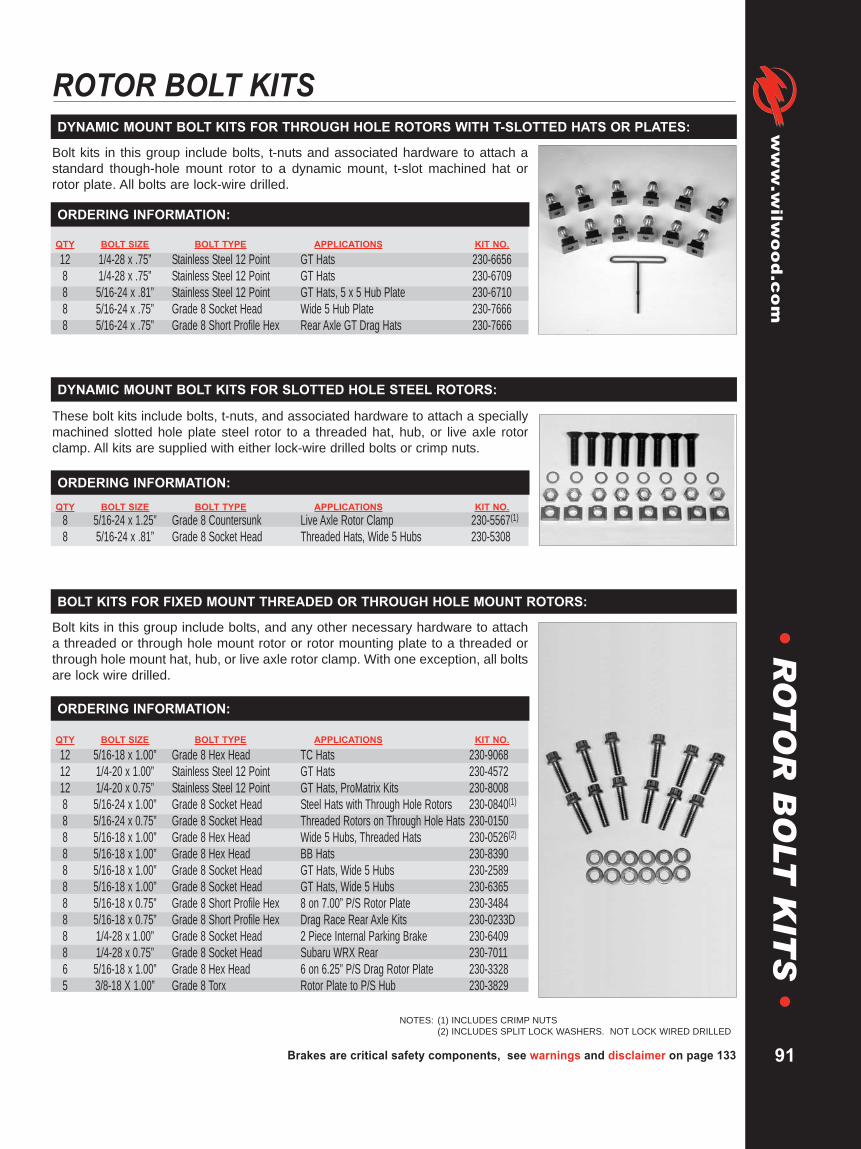
Brakes are critical safety components, see warnings and disclaimer on page 133
www.wilw
ood.com
91
•R
OT
OR
BO
LTK
ITS
•ROTOR BOLT KITS
QTY BOLT SIZE BOLT TYPE APPLICATIONS KIT NO.
12 1/4-28 x .75” Stainless Steel 12 Point GT Hats 230-66568 1/4-28 x .75” Stainless Steel 12 Point GT Hats 230-67098 5/16-24 x .81” Stainless Steel 12 Point GT Hats, 5 x 5 Hub Plate 230-67108 5/16-24 x .75” Grade 8 Socket Head Wide 5 Hub Plate 230-76668 5/16-24 x .75” Grade 8 Short Profile Hex Rear Axle GT Drag Hats 230-7666
DYNAMIC MOUNT BOLT KITS FOR THROUGH HOLE ROTORS WITH T-SLOTTED HATS OR PLATES:
Bolt kits in this group include bolts, t-nuts and associated hardware to attach astandard though-hole mount rotor to a dynamic mount, t-slot machined hat orrotor plate. All bolts are lock-wire drilled.
ORDERING INFORMATION:
NOTES: (1) INCLUDES CRIMP NUTS(2) INCLUDES SPLIT LOCK WASHERS. NOT LOCK WIRED DRILLED
QTY BOLT SIZE BOLT TYPE APPLICATIONS KIT NO.8 5/16-24 x 1.25” Grade 8 Countersunk Live Axle Rotor Clamp 230-5567(1)8 5/16-24 x .81” Grade 8 Socket Head Threaded Hats, Wide 5 Hubs 230-5308
DYNAMIC MOUNT BOLT KITS FOR SLOTTED HOLE STEEL ROTORS:
ORDERING INFORMATION:
These bolt kits include bolts, t-nuts, and associated hardware to attach a speciallymachined slotted hole plate steel rotor to a threaded hat, hub, or live axle rotorclamp. All kits are supplied with either lock-wire drilled bolts or crimp nuts.
QTY BOLT SIZE BOLT TYPE APPLICATIONS KIT NO.
12 5/16-18 x 1.00” Grade 8 Hex Head TC Hats 230-906812 1/4-20 x 1.00” Stainless Steel 12 Point GT Hats 230-457212 1/4-20 x 0.75” Stainless Steel 12 Point GT Hats, ProMatrix Kits 230-80088 5/16-24 x 1.00” Grade 8 Socket Head Steel Hats with Through Hole Rotors 230-0840(1)8 5/16-24 x 0.75” Grade 8 Socket Head Threaded Rotors on Through Hole Hats 230-01508 5/16-18 x 1.00” Grade 8 Hex Head Wide 5 Hubs, Threaded Hats 230-0526(2)8 5/16-18 x 1.00” Grade 8 Hex Head BB Hats 230-83908 5/16-18 x 1.00” Grade 8 Socket Head GT Hats, Wide 5 Hubs 230-25898 5/16-18 x 1.00” Grade 8 Socket Head GT Hats, Wide 5 Hubs 230-63658 5/16-18 x 0.75” Grade 8 Short Profile Hex 8 on 7.00” P/S Rotor Plate 230-34848 5/16-18 x 0.75” Grade 8 Short Profile Hex Drag Race Rear Axle Kits 230-0233D8 1/4-28 x 1.00” Grade 8 Socket Head 2 Piece Internal Parking Brake 230-64098 1/4-28 x 0.75” Grade 8 Socket Head Subaru WRX Rear 230-70116 5/16-18 x 1.00” Grade 8 Hex Head 6 on 6.25” P/S Drag Rotor Plate 230-33285 3/8-18 X 1.00” Grade 8 Torx Rotor Plate to P/S Hub 230-3829
BOLT KITS FOR FIXED MOUNT THREADED OR THROUGH HOLE MOUNT ROTORS:
Bolt kits in this group include bolts, and any other necessary hardware to attacha threaded or through hole mount rotor or rotor mounting plate to a threaded orthrough hole mount hat, hub, or live axle rotor clamp. With one exception, all boltsare lock wire drilled.
ORDERING INFORMATION:
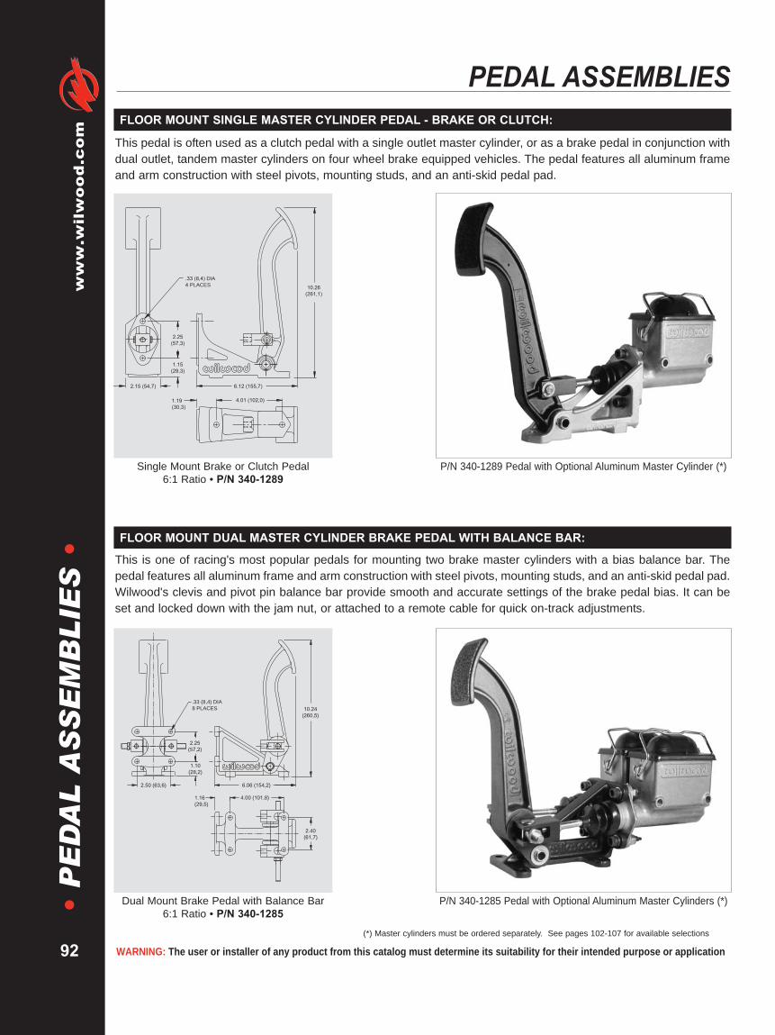
WARNING: The user or installer of any product from this catalog must determine its suitability for their intended purpose or application
www.wilwood.com
92
•P
ED
AL
AS
SE
MB
LIE
S•PEDAL ASSEMBLIES
This pedal is often used as a clutch pedal with a single outlet master cylinder, or as a brake pedal in conjunction withdual outlet, tandem master cylinders on four wheel brake equipped vehicles. The pedal features all aluminum frameand arm construction with steel pivots, mounting studs, and an anti-skid pedal pad.
2.25
(57,3)
1.15
(29,3)
2.15 (54,7)
.33 (8,4) DIA
4 PLACES
1.19
(30,3)
10.26
(261,1)
6.12 (155,7)
4.01 (102,0)
Single Mount Brake or Clutch Pedal6:1 Ratio • P/N 340-1289
P/N 340-1289 Pedal with Optional Aluminum Master Cylinder (*)
FLOOR MOUNT SINGLE MASTER CYLINDER PEDAL - BRAKE OR CLUTCH:
(*) Master cylinders must be ordered separately. See pages 102-107 for available selections
This is one of racing's most popular pedals for mounting two brake master cylinders with a bias balance bar. Thepedal features all aluminum frame and arm construction with steel pivots, mounting studs, and an anti-skid pedal pad.Wilwood's clevis and pivot pin balance bar provide smooth and accurate settings of the brake pedal bias. It can beset and locked down with the jam nut, or attached to a remote cable for quick on-track adjustments.
.33 (8,4) DIA
8 PLACES
2.25
(57,2)
1.10
(28,2)
2.50 (63,6) 6.06 (154,2)
4.00 (101,8)1.16
(29,5)
2.40
(61,7)
10.24
(260,5)
Dual Mount Brake Pedal with Balance Bar6:1 Ratio • P/N 340-1285
P/N 340-1285 Pedal with Optional Aluminum Master Cylinders (*)
FLOOR MOUNT DUAL MASTER CYLINDER BRAKE PEDAL WITH BALANCE BAR:

Brakes are critical safety components, see warnings and disclaimer on page 133
www.wilw
ood.com
93
•P
ED
AL
AS
SE
MB
LIE
S•
FORWARD SWING MOUNT SINGLE MASTER CYLINDER PEDAL - BRAKE OR CLUTCH:
1.19 (30,3)
.33 (8,4) DIA
4 PLACES
4.01 (102,0)
2.15 (54,7) 6.45 (164,1)
1.15
(29,3)
2.25
(57,3)
12.65
(321,9)
Single Mount Brake or Clutch Pedal7:1 Ratio • P/N 340-1290
This pedal is often used as a clutch pedal with a single outlet master cylinder, or as a brake pedal in conjunction withdual outlet, tandem master cylinders on four wheel brake equipped vehicles. The pedal features all aluminum frameand arm construction with steel pivots, mounting studs, and an anti-skid pedal pad.
P/N 340-1290 Pedal with Optional Aluminum Master Cylinder (*)
(*) Master cylinders must be ordered separately. See pages 102-107 for available selections
This popular pedal mounts two brake master cylinders with a bias balance bar. The pedal features all aluminum frameand arm construction with steel pivots, mounting studs, and an anti-skid pedal pad. Wilwood's clevis and pivot pinbalance bar provide smooth and accurate settings of the brake pedal bias. It can be set and locked down with thejam nut, or attached to a remote cable for quick on-track adjustments.
2.40
(61,7)
4.00 (101,8)
6.39 (162,6)
12.65
(321,9)
1.16 (29,5)
2.50 (63,6)
1.10
(28,0)
2.25
(57,2)
.33 (8,4)
8 PLACES
Dual Mount Brake Pedal with Balance Bar7:1 Ratio • P/N 340-1287
P/N 340-1287 Pedal with Optional Aluminum Master Cylinders (*)
FORWARD SWING MOUNT DUAL MASTER CYLINDER BRAKE PEDAL WITH BALANCE BAR:

WARNING: The user or installer of any product from this catalog must determine its suitability for their intended purpose or application
www.wilwood.com
94
•P
ED
AL
AS
SE
MB
LIE
S•PEDAL ASSEMBLIES
This pedal assembly operates the brakes and the clutch together in one unit and positions the master cylindersoutside of the firewall. It features all aluminum frame and arm construction with steel pivots, mounting studs, andanti-skid pedal pads. Wilwood's clevis and pivot pin balance bar provide smooth and accurate settings ofthe brake pedal bias. It can be set and locked down with the jam nut, or attached to a remote cable for quickon-track adjustments.
.344 DIA THRU
4 PLACES
1/4-20 THD
x .88 DP
2 PL
1.06
(26,9)
5/16-24 THD
STUD
6 PLACES
11.88 R
(301,8)
2.25 (57,2)
.44 (11,2)
.88
(22,4)
.50 (12,7)
2.25
(57,2)
7.50 (190,5)
2.75 (69,9)
2.62 (66,6) 2.62 (66,6)
2.62 (66,6)
1.44
(36,6)
.50 (12,7)
4.62
(117,3)
3.00
(76,2)
8.50 (215,9)
.31
(7,9)
Triple Mount Brake and Clutch Pedal with Balance Bar6.25:1 • P/N 340-3950
P/N 340-3950 Pedal with OptionalMaster Cylinders (*)
FORWARD SWING MOUNT TRIPLE MASTER CYLINDER PEDAL - ALUMINUM:
(*) Master cylinders must be ordered separately. See pages 102-107 for available selections
This steel pedal assembly was built for cars racing under rules that prohibit aluminum pedal arms. This assemblyoperates the brakes and the clutch together in one unit and positions the master cylinders outside of the firewall. Itfeatures an aluminum frame with steel arm construction, steel pivots, mounting studs, and anti-skid pedal pads.Wilwood's clevis and pivot pin balance bar provide smooth and accurate settings of the brake pedal bias. It can beset and locked down with the jam nut, or attached to a remote cable for quick on-track adjustments.
.344 DIA THRU
4 PLACES
1/4-20 THD
x .88 DP
2 PL
1.06
(26,9)
5/16-24 THD
STUD
6 PLACES
11.06 R
(280,9)
2.25 (57,2)
.44 (11,2)
.88
(22,4)
.50 (12,7)
2.25
(57,2)
7.50 (190,5)
2.75 (69,9)
2.62 (66,6) 2.62 (66,6)
2.62 (66,6)
1.44
(36,6)
.50 (12,7)
4.62
(117,3)
3.00
(76,2)
8.50 (215,9)
.31
(7,9)
Triple Mount Brake and Clutch Pedal with Balance Bar6.25:1 Ratio • P/N 340-6916
P/N 340-6916 Pedal with OptionalMaster Cylinders (*)
FORWARD SWING MOUNT TRIPLE MASTER CYLINDER PEDAL - STEEL:

Brakes are critical safety components, see warnings and disclaimer on page 133
www.wilw
ood.com
95
•P
ED
AL
AS
SE
MB
LIE
S•
REVERSE SWING MOUNT DUAL MASTER CYLINDER BRAKE PEDAL WITH BALANCE BAR:
This pedal mounts two brake master cylinders with a bias balance bar and positions the master cylinders inside thefirewall and away from engine heat. The pedal features all aluminum frame and arm construction with steel pivots,mounting studs, and an anti-skid pedal pad. Wilwood's clevis and pivot pin balance bar provide smooth and accuratesettings of the brake pedal bias. It can be set and locked down with the jam nut, or attached to a remote cable forquick on-track adjustments. Two ratios are offered to suit mounting and leverage requirements.
6.25:1 RATIO
11.71 (297,2)
5.1:1 RATIO
10.02 (254,5)
5/16-24 THD
STUD
4 PLACES
.50 (12,7)
2.29
(58,2)
.344 DIA
THRU
4 PLACES
3.00
(76,2)
1/4-20 THD
x .88 DEEP
4 PLACES
VIEW A-A
.51
(13,0)
1.00
(25,4)
4.61
(117,1)
.81
(20,6)2.62 (66,5)
5.27 (133,9)
.25 (8,4)
2.00 (50,8)
4.25 (108,0)
2.12
(53,8)
2.25 (57,2)
.39
(9,9) .90
(22,9)
Reverse Dual Mount Brake Pedal with Balance Bar5.1:1 Ratio - P/N 340-5180 • 6.25:1 Ratio - P/N 340-5181
P/N 340-5181 Pedal with OptionalMaster Cylinders (*)
(*) Master cylinders must be ordered separately. See pages 102-107 for available selections
AA
VIEW A-A
.44
5/16-24 THD
STUD
6 PLACES7.50 (190,5)
2.75
(69,9)
2.62
(66,6)
2.62
(66,6)
1.44
(36,6)
.50 (12,7) 2.62
(66,6)
.344 DIA
THRU
4 PLACES
4.62
(117,3)
3.00
(76,2)
1.08
(27,4)
1/4-20 THD
x .88 DEEP
4 PLACES
8.50 (215,9)
2.25 (57,2)
2.25
(57,2)
.88
(22,4)
.50 (12,7)
1.94 (49,3)
.31
(7,9)
6.25:1 RATIO
11.71 (297,2)
5.1:1 RATIO
10.02 (254,5)
Triple Mount Clutch and Brake Pedal with Balance Bar5.1:1 - P/N 340-4828 • 6.25:1 - P/N 340-33426.25:1 Brake / 5.1:1 Clutch - P/N 340-6451
P/N 340-3342 Pedal with OptionalMaster Cylinders (*)
This assembly combines the brake and clutch pedals together in one unit and positions the master cylinders insidethe firewall and away from engine heat. It features all aluminum frame and arm construction with steel pivots,mounting studs, and anti-skid pedal pads. Wilwood's clevis and pivot pin balance bar provide smooth and accuratesettings of the brake pedal bias. It can be set and locked down with the jam nut, or attached to a remote cable forquick on-track adjustments. Three ratio options are offered to suit mounting and leverage requirements.
REVERSE SWING MOUNT TRIPLE MASTER CYLINDER CLUTCH & BRAKE PEDAL WITH BALANCE BAR:

WARNING: The user or installer of any product from this catalog must determine its suitability for their intended purpose or application
www.wilwood.com
96
•P
ED
AL
AS
SE
MB
LIE
S•PEDAL ASSEMBLIES
(*) Master cylinders must be ordered separately. See pages 104-109 for available selections
This lightweight unit is ideal for Dirt Modifieds, Champ Cars, Sprint Cars and Midgets where master cylinders mustbe mounted in a remote location because of tight space constraints. Usually mounted to the driver’s left side chassisrail, the units balance bar controls two standard mount master cylinders with remote mounted reservoirs. The 60degree mounting angle allows for tight fit applications and easy accessibility. Strong cast aluminum housing andbalance bar weighs only 1.8 pounds. An adjuster knob is included with each assembly.
2.95 R
(74,9)
4.10 (104,1)
.56 (14,2)
5/16-24 THD STUD
4 PLACES
.44 (11,2).89 (22,6)
1.60 (40,6)
KNOB DETAIL
2.19
(55,6)
60¡
2.25 (57,2)
.40
(10,2)
.344 (8, 7) DIA THRU
4 PLACES
4.25
(108,0)
4.61 (117,1)
1.00
(25,4)3.00 (76,2)
.51
(13,0)
5.32
(135,1)
.40 (10,2)
1.62
(41,0)
60 Degree Balance Bar Assembly • P/N 340-4630 60 Degree Mount (*)
60 DEGREE BALANCE PEDAL ASSEMBLY:
Balance Bar
Remote Brake Bias Adjuster
Our balance bar assembly is designed to maximize travel and adjustabilityproviding increased front-to-rear bias control. The precision sphericalbearing with corrosion resistant finish is durable and smooth performing.The 3/8-24 threaded adjuster bar is high strength aircraft alloy and fittedwith lightweight, maintenance free clevises and thrust washers to eliminatebinding under extreme pivot angles.
BALANCE BAR ASSEMBLY:
DESCRIPTION PART NO.Remote Brake Bias Adjuster 340-4990
Wilwood’s Remote Balance Bar Cable Adjuster is used with balancebars to adjust front-to-rear brake bias during changing race conditions.The highly visible bright blue knob features a special bi-directionaldetente control providing the driver with positive adjustment feedback.The special five foot cable and housing (which can be cut to any lengthfor a custom fit) provides an optimum bending radius for easyinstallation and smooth performance in tight confines. The assemblycomes with two label faces for either front-to-rear or rear-to-frontadjustment. Standard 3/8-24 thread fits Wilwood and most commonlyused balance bars.
REMOTE BRAKE BIAS ADJUSTER:
ORDERING INFORMATION:
DESCRIPTION PART NO.Balance Bar 340-1757
ORDERING INFORMATION:

Brakes are critical safety components, see warnings and disclaimer on page 133
www.wilw
ood.com
97
•P
ED
AL
AS
SE
MB
LIE
S•
BRAKE PEDAL GUIDELINES:
Wilwood pedal assemblies and integrated balance bars have been designed specifically for racing applications.Properly set-up, this assembly will allow for the precise adjustment of front-to-rear brake bias. The advantages of anadjustable balance bar and dual master cylinders are:•Brake proportioning can be adjusted by use of different size master cylinder bores for front and rear brakes.•Front to rear brake balance can be fine tuned by adjusting the balance bar.•With two independent hydraulic systems, should one master cylinder fail, the other system may remain functional.
Brake pedals should be mounted securely. When possible, keep the master cylinder reservoir level higher than thehorizontal plane of the calipers to prevent excessive fluid drain back which can result in double pumping of the pedal.If this is not possible, a two pound residual pressurevalve should be plumbed into the brake line at the exitof the master cylinder to prevent fluid drain back (donot confuse the two pound valve with the ten poundversion; the ten pound valve is for use with drumbrakes only).
Brake pedals should be free to return when nopressure is being applied, allowing the master cylinderpushrod to return to its undepressed position. In somecases, the master cylinder spring (internal) may not bestrong enough to fully return the pushrod; in this casean additional pedal return spring can be used. Thereare two important items for consideration:
1. The brake pedal should have an adjustable return stop on it when a strong pedal return spring is used. Thisprevents the master cylinder from excessively banging the snap ring stop inside the master cylinder bore (visibleunder the rubber boot). Adjust the stop so the pedal stops returning at the point when the master cylinder pistonretracts against the snap ring, Figure 1.
2. The master cylinder piston must fully retract. If the master cylinder piston is not allowed to fully retract when thebrake pedal is not applied, the primary inside seal will not return past the small pressure relief hole (visible withinthe master cylinder reservoir on some master cylinders). This can cause excessive residual line pressure andcontribute to brake drag and an overheating condition, see Figure 1, Detail “A”.
BALANCE BAR ADJUSTINGThe balance bar is an adjustable lever (usually a threaded rod), that pivots on a spherical bearing and uses twoseparate master cylinders for the front and rear brakes. Most balance bars are part of a pedal assembly that alsoprovides a mounting for the master cylinders. When the balance bar is centered, it pushes equally on both mastercylinders creating equal pressure, given that the master cylinders are the same size bore. When adjusted as far aspossible toward one master cylinder it will push approximately twice as hard on that cylinder as the other.
To set up the balance bar,thread the master cylinderpushrods through theirrespective clevises to obtainthe desired position.Threading one pushrod intoits respective clevis meansthreading the other one outthe same amount. Sometimesthis will lead to a “cocked”balance bar when the pedal isin the relaxed position, seeFigure 2, “no pedal effort”.This is acceptable as long aseach master cylinder pushrodis completely free of pressurewhen the pedal is relaxed.
FRONT M/C
REAR M/C
FRONT M/C
REAR M/C
FRONT M/C
REAR M/C
NO PEDAL EFFORT
NOTE:
THE PUSHROD ADJUSTMENT DEPICTED IN THIS FIGURE IS REPRESENTATIVE OF A TYPICAL ASPHALT APPLICATION.
THAT IS, LARGE CALIPER PISTONS IN FRONT, SMALL CALIPER PISTONS IN THE REAR.
MODERATE PEDAL EFFORT HEAVY PEDAL EFFORT
Figure 2. Balance bar lever adjustment
MOUNTING PLATE
PEDAL STOP
ADJUSTMENT
NUT
PEDAL RETURN
SPRING
(OPTIONAL)
SEE DETAIL "A"
DETAIL "A"INTERNAL VIEW OF MASTER CYLINDER
LARGE
HOLE(S)
COUNTERSUNK
PRESSURE
RELIEF HOLE
PISTON MUST
FULLY RETRACT
PAST THE PRESSURE
RELIEF HOLE
PUSHROD ALLOWED TO FULLY
RETURN TO SNAP RING
Figure 1. Master cylinder pedal stop and return hole position
BALANCE BAR ADJUSTING:

WARNING: The user or installer of any product from this catalog must determine its suitability for their intended purpose or application
www.wilwood.com
98
•P
ED
AL
AS
SE
MB
LIE
S•PEDAL ASSEMBLIES
It is important that the operation of the balancebar functions without interference by overadjustment. This can occur when a clevis jamsagainst the side of the pedal or the lever (bolt)hits the pedal bore during any point of pedaltravel, Figure 3.
Lever movement should be unimpededthroughout pedal travel. In the neutral position,clevises should have between .20” - .25” totalclearance between the side of the pedal. Thelarge washers between the pedal and clevisshould remain loose. Make sure that the mastercylinder pushrods remain true in relationship tothe cylinder during entire pedal travel; pushrodsshould not be pushing master cylinder pistons atan angle. See Figure 4.
NOTE: In its non-depressed position, the pedaland balance bar should allow the pushrod of themaster cylinders to fully return. This can bechecked by feeling pushrods for very slightmovement, not loose movement. Master cylinderpistons should be against the retaining snap ring(under boot).
INTERNAL BORE
OF PEDAL HOUSING
PEDAL HOUSING
WASHER
CLEVIS
INCORRECT ADJUSTMENT:
LEVER (BOLT) SHOULD NOT
BIND ON PEDAL HOUSING
BORE THROUGH ENTIRE
PEDAL TRAVEL
Figure 3. Balance bar lever interference
PROPER ALIGNMENTINCORRECT PUSH ROD ALIGNMENT
DIMENSION A + B ADDED TOGETHER MUST BE IN THE .20" - .25" RANGE
A
B
Figure 4. Example of pushrod alignment
BALANCE BAR ADJUSTING:
Pedal ratio, or mechanical leverage is the ratio calculated from the length from the pivot point of the pedal to thecenter of the foot pedal (A), divided by the length from the pivot point to the master cylinder pushrod (B). Refer tothe figures below.
Mechanical leverage is simply a means of increasing the brake force without increasing your leg effort. As “A” getslonger and “B” gets shorter, the mechanical leverage increases brake force without pushing harder on the pedal. Thedisadvantage is that the pedal stroke also increases, requiring you to push the pedal further.
With a 1 inch master cylinder stroke, a 100 pound push on the pedal, and the pedal having a 4:1 ratio, the force is 4x 100 = 400 pounds, and the stroke is 4 x 1 = 4 inches. With a 100 pound push on the pedal, and the pedal havinga 6:1 ratio, the force is 6 x 100 = 600 pounds, and the stroke is 6 x 1 = 6 inches.
If uncertain about which pedal ratio is right for your application, a 6:1 ratio is an excellent starting point.
F
A
A
A A
P
P
P
B
B
BB
F
F
PF
Figure 1 Figure 2 Figure 3 Figure 4
A = Distance from pivot point to middle of push / pull point
B = Distance from pivot to point of push on master cylinder
P = Pivot point
F = Force or push
PEDAL RATIOS / MECHANICAL LEVERAGE:
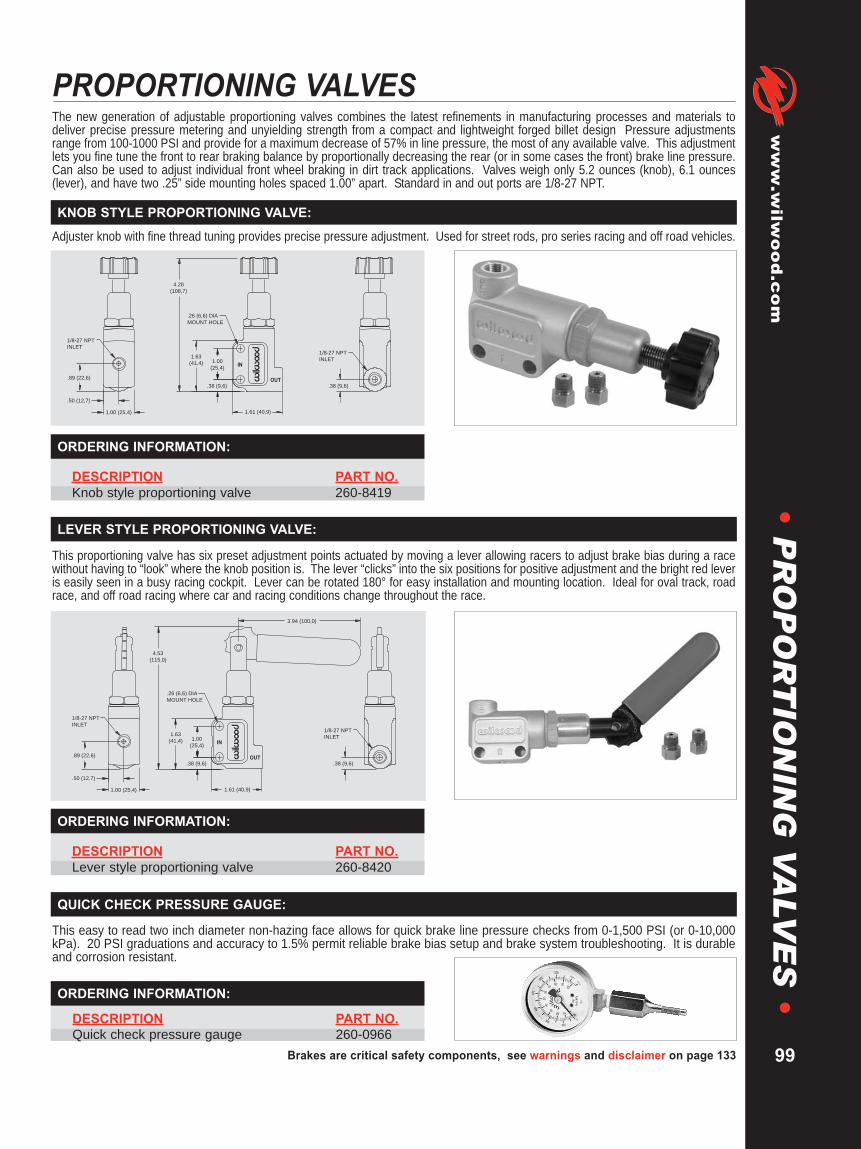
Brakes are critical safety components, see warnings and disclaimer on page 133
www.wilw
ood.com
99
•P
RO
PO
RT
ION
ING
VA
LVE
S•
PROPORTIONING VALVESThe new generation of adjustable proportioning valves combines the latest refinements in manufacturing processes and materials todeliver precise pressure metering and unyielding strength from a compact and lightweight forged billet design Pressure adjustmentsrange from 100-1000 PSI and provide for a maximum decrease of 57% in line pressure, the most of any available valve. This adjustmentlets you fine tune the front to rear braking balance by proportionally decreasing the rear (or in some cases the front) brake line pressure.Can also be used to adjust individual front wheel braking in dirt track applications. Valves weigh only 5.2 ounces (knob), 6.1 ounces(lever), and have two .25” side mounting holes spaced 1.00” apart. Standard in and out ports are 1/8-27 NPT.
Adjuster knob with fine thread tuning provides precise pressure adjustment. Used for street rods, pro series racing and off road vehicles.
This proportioning valve has six preset adjustment points actuated by moving a lever allowing racers to adjust brake bias during a racewithout having to “look” where the knob position is. The lever “clicks” into the six positions for positive adjustment and the bright red leveris easily seen in a busy racing cockpit. Lever can be rotated 180° for easy installation and mounting location. Ideal for oval track, roadrace, and off road racing where car and racing conditions change throughout the race.
OUT
IN1.00
(25,4)
1.00 (25,4)
.50 (12,7)
.89 (22,6)
1.63
(41,4)
4.53
(115,0)
1.61 (40,9)
.38 (9,6)
3.94 (100,0)
.38 (9,6)
.26 (6,6) DIA
MOUNT HOLE
1/8-27 NPT
INLET1/8-27 NPT
INLET
OUT
IN1.00
(25,4)
1.00 (25,4)
.50 (12,7)
.89 (22,6)
1.63
(41,4)
4.28
(108,7)
1.61 (40,9)
.38 (9,6) .38 (9,6)
.26 (6,6) DIA
MOUNT HOLE
1/8-27 NPT
INLET1/8-27 NPT
INLET
KNOB STYLE PROPORTIONING VALVE:
LEVER STYLE PROPORTIONING VALVE:
DESCRIPTION PART NO.Lever style proportioning valve 260-8420
ORDERING INFORMATION:
DESCRIPTION PART NO.Knob style proportioning valve 260-8419
ORDERING INFORMATION:
DESCRIPTION PART NO.Quick check pressure gauge 260-0966
This easy to read two inch diameter non-hazing face allows for quick brake line pressure checks from 0-1,500 PSI (or 0-10,000kPa). 20 PSI graduations and accuracy to 1.5% permit reliable brake bias setup and brake system troubleshooting. It is durableand corrosion resistant.
ORDERING INFORMATION:
QUICK CHECK PRESSURE GAUGE:

WARNING • NOT A LINE LOCK • NOT FOR STREET USETHIS DEVICE IS INTENDED FOR SPECIALIZED RACING USE ONLY. READ INSTRUCTIONS AND ALL WARNINGS CAREFULLY.INSTALLATION OF THIS COMPONENT SHOULD ONLY BE PERFORMED BY PERSONS EXPERIENCED IN THE INSTALLATION ANDPROPER OPERATION OF DISC BRAKE SYSTEMS. IT IS THE RESPONSIBILITY OF THE PERSON INSTALLING ANY BRAKECOMPONENT OR KIT TO DETERMINE THE SUITABILITY OF THE COMPONENT OR KIT FOR THAT PARTICULAR APPLICATION.RACING EQUIPMENT AND BRAKES MUST BE MAINTAINED AND SHOULD BE CHECKED REGULARLY FOR FATIGUE, DAMAGE ANDWEAR.
FOR OFF ROAD USE ONLYBEFORE OPERATING VEHICLE, TEST THE BRAKES UNDER CONTROLLED CONDITIONS. MAKE SEVERAL STOPS IN A SAFE AREA FROM LOW SPEEDS AND ONLYGRADUALLY WORK UP TO HIGHER SPEEDS. DO NOT RACE ON UNTESTED BRAKES! ALWAYS UTILIZE SAFETY RESTRAINT SYSTEMS WHILE OPERATING VEHICLE.
IMPORTANT: READ DISCLAIMER OF WARRANTY INCLUDED WITH THE COMPONENTS.
WARNING: The user or installer of any product from this catalog must determine its suitability for their intended purpose or application
www.wilwood.com
100
LINE SHUT-OFF VALVE
WILWOOD LINE SHUT-OFF VALVE:
This valve can be used as a brake shut-off. When energized, thevalve will block pressure from reaching downstream. The valve doesnot prevent fluid from returning to the master cylinder. This eliminatesthe possibility of trapping pressure when activating the valve.
Mounting/Routing: Position the brake shut-off valve between themaster cylinder and the caliper to be shut-off. Mount securely with thebleed screw in the up position utilizing the mounting slots in thebracket using two mounting screws (not provided). The in/out brakeshut-off ports are 1/8-27 NPT threads. An adapter may be requiredfrom the port fittings of the unit (included) to the brake line tubingdepending upon the application. Run a brake line from the mastercylinder to the “IN” port of the brake shut-off. Run another line fromthe “OUT" port of the brake shut-off to the caliper you want to control.The brake shut-off may be bled through the top bleed screw ifnecessary.
Wiring: The lead wires should be connected to a 12 volt, 5 amp (recommended) fused power source through a toggleswitch. Always be sure to switch off the power to the line shut-off when the unit is not needed.
1.67 (42,4)
2.16 (54,9)
1.15
(29,2)
1.67 (42,5)
2.00 (50,8)
1.00 (25,4) .65 (16,5)
1.00
(25,4)
1.63
(41,3)
4.28
(108,7)
3.09 (78,5)
2 PLACES
.38 (9,5)
.38 (9,5)
#18 x 24" LONG
(2 WIRES)
.20 (5,1) WD x
.26 (6,6) LG
MOUNT SLOT
.26 (6,6) DIA
MOUNT HOLE
1/8-27 NPT
INLET
1/8-27 NPT
OUTLET
.50
(12,7)
.50
(12,7)
1.01
(25,5)
3.63
(92,1)
IN
OUT
WARNINGNOT A LINE LOCK
This device is intended for
specialized racing use
only. Read instructions
and all warnings carefully.
NOT FOR STREET USE
Line Shut-off, Mounting Dimensions
Wilwood’s Line Shut-off Valve
DESCRIPTION PART NO.Line Shut-Off Valve 260-9921
ORDERING INFORMATION:
•L
INE
SH
UT-O
FF
VA
LVE
•

Brakes are critical safety components, see warnings and disclaimer on page 133
www.wilw
ood.com
101
•S
EL
FB
LE
ED
LIN
ES
/CH
EC
KV
ALV
E•
SELF BLEED LINES / CHECK VALVE
FLOW
260-3501
FLOW
260-3501
FRONT MASTER
CYLINDER
FLOW VALVE
FLOW VALVE
TEE FITTING MUST BE LOCATED DIRECTLY ON
THE MASTER CYLINDER, OR STACK TWO (2)
BANJO FITTINGS
FLOW VALVES SHOULD BE LOCATED AS CLOSE
AS POSSIBLE TO THE MASTER CYLINDER AND
BEFORE THE LINES TEE OFF TO CALIPERS
FRONT CALIPERS
BLEED LINE
BALANCE BAR DUAL MASTER CYLINDER SETUP, FLOW VALVE INSTALLATION DIAGRAM:
DESCRIPTION PART NO.Check Valve (flow control valve) 260-3501
ORDERING INFORMATION:
Wilwood compact Check Valves, or Flow Control Valves are used in conjunction with our caliper Self Bleed Lines. Togetherthey form a closed loop brake fluid system that allows small amounts of brake fluid to circulate every time the brake pedal isdepressed, thereby eliminating the possibility of localized fluid boiling and build-up of gases within the brake fluid. Gasesend up being vented back into the master cylinder reservoir rather than trapped within the caliper and brake lines. The resultis a firmer, more consistent brakepedal under severe brakingconditions. Our Check Valveaccepts standard 1/8-27 NPTfittings. For plumbing instructionsrequest Wilwood’s Data Sheet,DS-213.
CHECK VALVE:
1.60 (40,6)
FLOW
1/8-27 NPT
BOTH ENDS
.63 (15,9)
DESCRIPTION PART NO. DESCRIPTION PART NO.STR (1.62” rotor) 190-7507 SL III, SL-GT, LC-GT Self Bleed Line (1.25” rotor) 190-4743Superlite 4 / 6 (1.25” rotor) 190-8310 GN III (1.38” rotor) 190-3615GT III (1.38” rotor) 190-4357 Integra Series (1.25 / 1.31 / 1.38” rotor) 190-5144Prolite 6 / Prolite 6R (1.38” rotor) 190-5604
ORDERING INFORMATION:
Wilwood’s Self Bleed Lines are designed for a precise, low profile fit toaccommodate gravity bleed and fluid recirculation systems. Each line ispressure tested to ensure quality and performance. For detailedplumbing instructions, request Wilwood’s Dynamic Bleed SystemInstallation Diagram / Instructions, DS-213.
SELF BLEED LINES:

WARNING: The user or installer of any product from this catalog must determine its suitability for their intended purpose or application
www.wilwood.com
101a
•M
AS
TE
RC
YL
IND
ER
S•
MASTER CYLINDERS
MAX
MIN
2.35 (59,7) 2.35 (59,7)3.31 (84,1)
MAX
MIN
4.58 (116,3)
3.70(94,0)
3.70(94,0)
SMALL RESERVOIR, 7 OUNCE, P/N 260-10204
MOUNTING BRACKET, P/N 250-10263 MASTER CYLINDER
LARGE RESERVOIR, 10 OUNCES, P/N 260-10205
2.00 (50,8)
2.70(68,6)
2.25(57,2)
1.19 (30,2) 2.22 (56,4).41(10,4)
.61 (15,5)
.54 (13,7)MOUNTINGHOLE
1.92 (48,8)
3.36 (85,4) 4.46 (113,3)7.82 (198,6)
1.75 (44,5)
5/16-24 THD
.40 (10,2) MOUNTING HOLE
1/8-27NPTOUTLET
.88
Minimum Mounting Requirements for Mounting Bracket, M/C and Reservoirs
DESCRIPTION PART NO.5/8” Combination M/C Kit (1.2 stroke) 260-103713/4” Combination M/C Kit (1.2 stroke) 260-1037213/16” Combination M/C Kit (1.2 stroke) 260-103737/8” Combination M/C Kit (1.2 stroke) 260-103741” Combination M/C Kit (1.2 stroke) 260-103751-1/8” Combination M/C Kit (1.2 stroke) 260-10376
REBUILD KITS PART NO.Rebuild Kit, 5/8” Combination 260-10513Rebuild Kit, 3/4” Combination 260-3881Rebuild Kit, 13/16” Combination 260-5921Rebuild Kit, 7/8” Combination 260-3882Rebuild Kit, 1” Combination 260-3883Rebuild Kit, 1-1/8” Combination 260-3884
Remote Reservoir Hose, 1/4” I.D. 220-10444(Available Bulk, By the Foot)
ORDERING INFORMATION:
MAX
MIN
.88
CAP
P/N 330-7641
(FITS BOTH
SIZES)
CLAMP
P/N 260-10342
HOSE
P/N 220-10444
RESERVOIR
P/N 260-10204
(7 OUNCE)
P/N 260-10205
(10 OUNCE)
MOUNTING
BRACKET
P/N 220-10263
INLET ADAPTER
P/N 260-10264
Remote Reservoir Configuration
Compact “Short” Remote Master Cylinder
Wilwood’s compact combination master cylinders have beenfully redesigned for limited space applications requiring theoutput capacity of a full size master cylinder.
Four mounting options with choices for direct or remotemounting of seven or ten ounce reservoirs that include animpact resistant threaded cap with an internal baffle and seals.
Over 2” additional clearance compared to full size mastercylinders, the ultra short 3.37” compact body provides 2.16” ofadditional clearance between the mounting flange and thefluid outlet.
Standard 1/8” NPT outlet ports provide a positive seal andreduce the potential for stripped threads. A full 1.12” of pistonstroke meets or exceeds the stroke capacity of most full sizemaster cylinders.
Master cylinder aluminum bodies are coated with Wilwood’sown black e-coat to resist corrosion and maintain a durablelong lasting finish.
COMPACT COMBINATION REMOTE MASTER CYLINDER KIT:

Brakes are critical safety components, see warnings and disclaimer on page 133
www.wilw
ood.com
101b
•M
AS
TE
RC
YL
IND
ER
S•
3.00 (76,2)
7/82.94
(74,7)
3.09 (78,5)
5.56 (141,2)
2.25
(57,2)
1.25 (31,8)
.34 (8,6) MOUNTING
HOLES
.62 (15,7)
.28 (7,1)
MOUNTING
HOLES
MOUNTING BRACKET MASTER CYLINDER
MIN
MAX3.69
(93,7)
2.62 (66,5)
.94 (23,9)1.94 (49,3)
MIN
4.31
(109,5)
4.75 (120,7)
2.06 (52,3)
2.25
(57,2)
RESERVOIR, SMALL (4.0 OZ) RESERVOIR, LARGE (10.7 OZ)
2.88 (73,2)
1.19
(30,2)
.41 (10,4)
2.00 (50,8) 3/8-24 THREAD
OUTLET
MAX
Minimum Mounting Requirements for Mounting Bracket, M/C and Reservoirs
DESCRIPTION PART NO.5/8” Combination M/C Kit (1.3 stroke) 260-33723/4” Combination M/C Kit (1.1 stroke) 260-337413/16” Combination M/C Kit (1.1 stroke) 260-59207/8” Combination M/C Kit (1.2 stroke) 260-33761” Combination M/C Kit (1.0 stroke) 260-33781-1/8” Combination M/C Kit (1.0 stroke) 260-3380
REBUILD KITS PART NO.Rebuild Kit, 5/8” Combination 260-3880Rebuild Kit, 3/4” Combination 260-3881Rebuild Kit, 13/16” Combination 260-5921Rebuild Kit, 7/8” Combination 260-3882Rebuild Kit, 1” Combination 260-3883Rebuild Kit, 1-1/8” Combination 260-3884
Push Rod 230-8947Remote Reservoir Hose, 3/8” I.D. 220-5613(Available Bulk, By the Foot)
ORDERING INFORMATION:
MIN
MAX
MIN
MAX
REMOTE MOUNTING BRACKET
(250-3381)
O-RING (210-3397)
REMOTE HOSE (220-3357)REMOTE INLET ADAPTER
(260-3396)
RESERVOIR CAP (330-4355)
(FITS BOTH SIZES)
RESERVOIR
10.7 OZ
(260-5751) RESERVOIR
4.0 OZ
(260-5752)
CLAMP ASSEMBLY
(260-3393)
CLAMP ASSEMBLY (260-3393)
LARGE FILTER
(260-3394)
SMALL FILTER
(260-3395)
BLEED SCREW
(220-3405)
OUTLET
3/8-24
THREAD
O-RING (210-3398)
MASTER CYLINDER
9.87 (250,7)
FLANGE MOUNTING HOLE,
.34 (8,6) DIA, 2 PLACES
2.25 (57,2) APART
SIDE MOUNTING HOLE, .34 (8,6) DIA, 2 PLACES
3.00 (76,2) APART
PUSH ROD
5/16-24 THREAD
7/8
Individual Components with Part NumbersIndividual Kit Components
Combination Remote Master Cylinder
Six different bore sizes and four different installationconfigurations are available in this master cylinder kit.Precision machined from high strength aluminum, this kitincludes both small and large size reservoirs which canbe mounted directly on the master cylinder or remotelymounted for more convenient service access. Standardmounting bolt hole configurations provide easyapplications for racing and off road vehicles, specialtycars, recreation and industrial vehicles.
COMBINATION REMOTE MASTER CYLINDER KIT:
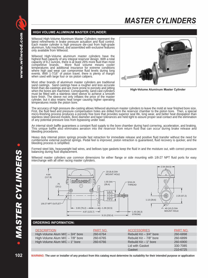
WARNING: The user or installer of any product from this catalog must determine its suitability for their intended purpose or application
www.wilwood.com
102
•M
AS
TE
RC
YL
IND
ER
S•
MASTER CYLINDERSHIGH VOLUME ALUMINUM MASTER CYLINDER:
Wilwood High-Volume Aluminum Master Cylinders represent thelatest refinements in brake pressure actuation and fluid control.Each master cylinder is high pressure die-cast from high-gradealuminum, fully machined, and assembled with exclusive featuresonly available from Wilwood.
Wilwood High-Volume aluminum master cylinders have thehighest fluid capacity of any integral reservoir design. With a totalcapacity of 8.2 ounces, there is at least 26% more fluid than mostcompetitive brands. More fluid volume means coolertemperatures and additional insurance for extreme conditionswhere high pad wear can compromise fluid levels during longevents. With 1-7/16" of piston travel, there is plenty of marginwhen used with large four or six piston calipers.
Most other brands of aluminum master cylinders are traditionalsand castings. Sand castings have a rougher and less accuratefinish than die-castings and are more prone to porosity and pittingwhen the bores are machined. Consequently, sand-cast cylindersmust be fitted with a stainless steel sleeve to achieve a smoothbore finish. The sleeve not only inflates the price of the mastercylinder, but it also retains heat longer causing higher operatingtemperatures inside the piston bore.
The accuracy of high pressure die-casting allows Wilwood aluminum master cylinders to leave the mold at near finished bore size.First, the fluid feed and pressure compensation holes are drilled from the reservoir chamber to the piston bore. Then, a specialmicro-finishing process produces a porosity free bore that provides superior seal life, long wear, and better heat dissipation thanstainless steel sleeved models. Bore diameter and taper tolerances are held tight to assure proper seal contact and the eliminationof any potential pressure loss from bypassing under load.
An internal slosh baffle guarantees a constant fluid supply to the bore chamber during hard cornering, acceleration, and braking.This unique baffle also eliminates aeration into the reservoir from return fluid that can occur during brake release andbleeding procedures.
Heavy duty internal piston springs provide fast retraction for immediate release and positive fluid transfer without the need forcumbersome external pushrod springs. Pedal feel is improved, piston retraction is guaranteed, fluid recovery is quicker, and thebleeding process is simplified.
Formed steel lids, heavyweight bail wires, and bellows type gaskets keep the fluid in and the moisture out, with correct pressurebalancing during fluid displacement.
Wilwood master cylinders use common dimensions for either flange or side mounting with 1/8-27 NPT fluid ports for easyinterchange with all other racing master cylinders.
High-Volume Aluminum Master Cylinder
5/16-24
THREAD
.40 (10,2) DIA
MOUNT HOLE
1.13 (28,6)
.75
(19,1)
4.64
(117,8)
2.25 (57,2)
2.54 (64,5)
3.00 (76,2)
4.87 (123,7)
9.15 (232,4)
1.43 (36,3)
STROKE
1/8-27 NPT OUTLET
.33 (8,4) DIA
MOUNT HOLE
1.55 DIA
(39,4)
1.28 (32,5)
DESCRIPTION PART NO. ACCESSORIES PART NO.High-Volume Alum M/C – 3/4" bore 260-6764 Rebuild Kit – 3/4" bore 260-6898High-Volume Alum M/C – 7/8" bore 260-6765 Rebuild Kit – 7/8” bore 260-6899High-Volume Alum M/C – 1" bore 260-6766 Rebuild Kit – 1" bore 260-6900
Lid with Gasket 330-7085Gasket 210-6725
ORDERING INFORMATION:
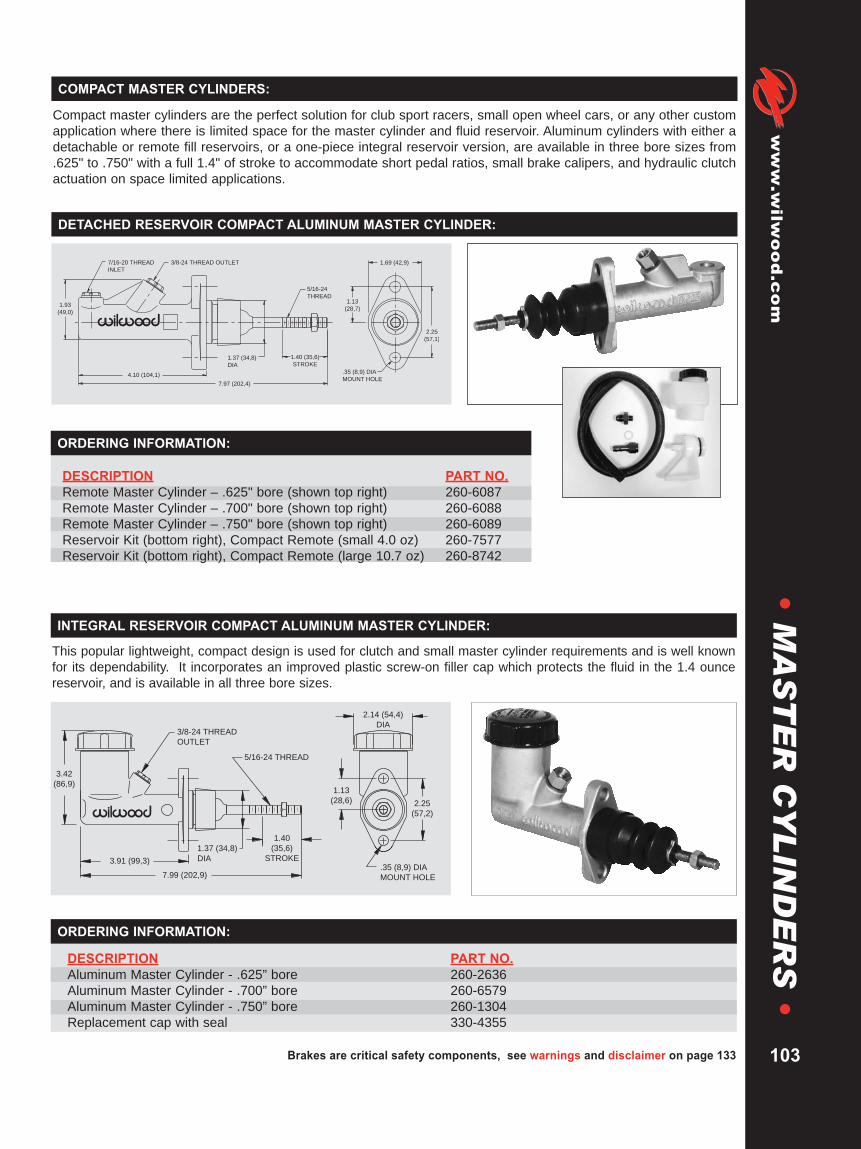
Brakes are critical safety components, see warnings and disclaimer on page 133
www.wilw
ood.com
103
•M
AS
TE
RC
YL
IND
ER
S•
7.99 (202,9)
3.91 (99,3)
1.37 (34,8)
DIA
1.40
(35,6)
STROKE.35 (8,9) DIA
MOUNT HOLE
2.25
(57,2)
1.13
(28,6)
2.14 (54,4)
DIA
3.42
(86,9)
3/8-24 THREAD
OUTLET
5/16-24 THREAD
This popular lightweight, compact design is used for clutch and small master cylinder requirements and is well knownfor its dependability. It incorporates an improved plastic screw-on filler cap which protects the fluid in the 1.4 ouncereservoir, and is available in all three bore sizes.
ORDERING INFORMATION:
INTEGRAL RESERVOIR COMPACT ALUMINUM MASTER CYLINDER:
DESCRIPTION PART NO.Aluminum Master Cylinder - .625” bore 260-2636Aluminum Master Cylinder - .700” bore 260-6579Aluminum Master Cylinder - .750” bore 260-1304Replacement cap with seal 330-4355
DESCRIPTION PART NO.Remote Master Cylinder – .625" bore (shown top right) 260-6087Remote Master Cylinder – .700" bore (shown top right) 260-6088Remote Master Cylinder – .750" bore (shown top right) 260-6089Reservoir Kit (bottom right), Compact Remote (small 4.0 oz) 260-7577Reservoir Kit (bottom right), Compact Remote (large 10.7 oz) 260-8742
ORDERING INFORMATION:
Compact master cylinders are the perfect solution for club sport racers, small open wheel cars, or any other customapplication where there is limited space for the master cylinder and fluid reservoir. Aluminum cylinders with either adetachable or remote fill reservoirs, or a one-piece integral reservoir version, are available in three bore sizes from.625" to .750" with a full 1.4" of stroke to accommodate short pedal ratios, small brake calipers, and hydraulic clutchactuation on space limited applications.
.35 (8,9) DIA
MOUNT HOLE
1.37 (34,8)
DIA
1.40 (35,6)
STROKE
1.93
(49,0)
1.13
(28,7)
1.69 (42,9)
2.25
(57,1)
3/8-24 THREAD OUTLET7/16-20 THREAD
INLET
5/16-24
THREAD
7.97 (202,4)
4.10 (104,1)
COMPACT MASTER CYLINDERS:
DETACHED RESERVOIR COMPACT ALUMINUM MASTER CYLINDER:

WARNING: The user or installer of any product from this catalog must determine its suitability for their intended purpose or application
www.wilwood.com
104
•M
AS
TE
RC
YL
IND
ER
S•
MASTER CYLINDERSTANDEM MASTER CYLINDER:
Made from durable lightweight aluminum with a large capacity plastic reservoir and dual outlet bores, this master cylinderutilizes standard O.E.M. internal components. Standard factory mounting bolt holes can be adapted to racing pedalassemblies with an optional mounting adapter bracket (including push rod and dust boot, see diagram below). This lightweight(2.5 pounds) reliable master cylinder is used for Drag Racing, Late Model Stock Cars, Street Rod and Off Road applications.
.34 (8,6)
DIA
MOUNT
HOLE
3/8-24 THREAD
1.50 (38,1)
DIA
1/2-20 THREAD
INVERTED FLARE
OUTLET "A"
9/16-20 THD
INVERTED
FLARE
OUTLET "B"
3.61 (91,7)
4.27 (108,5)2.94 (74,7)
8.14 (206,8)
12.42 (315,5)
4.83
(122,7)
.55
(14,0)
1.35
(34,3)
STROKE
1.60
(40,6)
3.20 (81,3)
DESCRIPTION PART NO.1-1/16” Tandem Master Cylinder 260-4893Tandem Master Cylinder Rebuild Kit (1-1/16” bore) 260-4896Tandem Master Cylinder Kit (includes m/c, boot, pushrod, retainer) 260-4894Universal Bracket Kit, (tandem master cylinder to fire wall) 250-2406Bracket Adapter Kit (tandem master cylinder to single brake pedal) 250-3677Replacement tube adapter fitting (3/16 x 1/2-20) 220-5247Replacement tube adapter fitting (3/16 x 9/16-20) 220-5248
Shown with kit P/N: 260-4894
ORDERING INFORMATION:
1.32 (33,5) MOUNT CENTER
0.70 (17,8) STROKE
1.82 (46,2)
4.30 (109,0)
1.48 (37,5)
3.46 (87,8)
2.48 (62,9)
5.04 (127,9)
.33 (8,3) DIA
MOUNT HOLE
.25 (6,4)
LEVER
HOLES
This super lightweight (only .55 pounds) 1/2” bore aluminum master cylinder designed specifically for Kart and Jr.Dragster racing applications incorporates an adjustable lever ratio with a remote mount clear fluid reservoir for easymonitoring. The assembly comes ready to install and includes billet bracket, lockwired drilled hardware and fluid linefitting. The unit is best utilized in conjunction with Wilwood’s Kart / Jr. Dragster caliper (see page 48).
DESCRIPTION PART NO.Master Cylinder with remote mount reservoir 260-5520Fitting, Straight, Brass, 1/8-27 NPT x 3/16 220-5487Hose, 1/4” I.D. x 1.15” Long 220-5534Clamp, .50” Diameter 260-5556Reservoir Assembly with Cap 330-4615Cap Assembly 330-6014Lever 330-5513
ORDERING INFORMATION:
KART / JR. DRAGSTER MASTER CYLINDER:

Brakes are critical safety components, see warnings and disclaimer on page 133
www.wilw
ood.com
105
•M
AS
TE
RC
YL
IND
ER
S•
Tandem master cylinders provide one of the safest ways to actuate four wheel or dual caliper axle brake systems.This versatile, lightweight and easily adapted master cylinder provides single pushrod activation of two separatebrake fluid circuits. By completely isolating the fluid reservoirs and circuits, the front and rear brakes are able tooperate independently of each other and provide a safety net should any one side of the system become inoperable.The cylinder features 50/50 output from a 1.00" bore with 1.10" stroke. It is a great match for Wilwood's Bolt-On DiscBrake Kits, systems configured from OE components, and a variety of industrial applications. This master cylindercan be bolted directly to Wilwood's single mount pedals. The kit is shipped complete with the master cylinder and allnecessary hardware including 30 inches of hose that can be cut to the desired length for remote mounting of the two4 ounce fluid reservoirs.
2.77 (70,4) 3.38 (85,9)
1.10 (27,9)
STROKE
2.91 (73,9)
PLUG5/16-24
THREAD
2.25 (57,2)
1.12 (28,4)
.34 (8,6) DIA
MOUNT HOLE
BLEED
SCREW
7.03 (178,6)
11.53 (299,9)
OUTLET FITTING
3/16 TUBE
INVERTED
FEMALE FLARE
2.58 (65,5)
1.88 (47,8)
DESCRIPTION PART NO.Combination Remote Tandem M/C Kit-1.00” Bore 260-7563Push Rod 230-6926
Tandem Master Cylinder with Remote Inlet Adapters
Fluid Reservoirs and Remote Mount Brackets
REMOTE MOUNTING BRACKET
(250-3381)
REMOTE INLET ADAPTER
(260-3396)
O-RING (210-3397)
O-RING
(210-3398)
REMOTE HOSE (220-3357)
MASTER CYLINDER
SHOWN FOR REFERENCE
CLAMP ASSEMBLY (260-3393)
RESERVOIR CAP (330-4355)
(FITS BOTH RESERVOIRS)
4 OZ RESERVOIR
(260-5752)
FILTER (260-3394)
FITS INTO RESERVOIR
MIN
MAX
Remote Reservoir Configuration
COMBINATION REMOTE TANDEM MASTER CYLINDER:
ORDERING INFORMATION:
MOUNTING DIMENSIONS:

WARNING: The user or installer of any product from this catalog must determine its suitability for their intended purpose or application
www.wilwood.com
106
•M
AS
TE
RC
YL
IND
ER
S•
MASTER CYLINDERS
Manufactured from durable lightweightaluminum with a large capacity (4.2 in3
minimum, 8.0 in3 maximum) plasticreservoir and dual outlet bores, thismaster cylinder utilizes standardOriginal Equipment Manufacturer(OEM) internal components. Standardfactory mounting bolt holes can beadapted to racing pedal assemblies withan optional mounting adapter bracket.This lightweight (less than one pound)reliable master cylinder and unique newdesign makes it a perfect fit for a widerange of applications.
Compact design is perfect for applications where space is limited. Only 4.50” inches high with a body length of 6.00” (totalincluding pushrod, 11.50”) with a width of 1.80”.
Currently available in 5/8” bore with integral reservoirs with a 1.31” stroke. Call Wilwood customer service at (805) 388-1188 forthe availability of other bore sizes. Mounts easily with side mounts that accommodate 5/16” mounting bolts. Unit comes with asingle sided M10 fluid inlet. Maximum operating pressure of 1,500 PSI for the toughest jobs.
Master cylinder comes ready to install with pushrod, clevis and dust boot. Compatible with DOT 3 and 4 brake fluids.
DESCRIPTION PART NO.5/8” Bore Master Cylinder 260-10234
TM1 TANDEM MASTER CYLINDER:
ORDERING INFORMATION:
4.51
(114,6)
6.26 (159,0)
11.53 (292,9)
2.41 (61,2) .58 (14,7)
3.53 (89,7)
.39 (9,9) DIA
.67 (17,0)
.33 (8,4) DIA
MOUNT HOLE
M10 X 1.00 THREAD
BANJO OUTLET FITTING
2.17 (55,1)
1.44
(36,6)
1.74
(44,2)
.55 (14,0)
.34 (8,6)
WILWOODENGINEERING
MIN
MAX
MOUNTING DIMENSIONS:
TM1 Tandem Master Cylinder

Brakes are critical safety components, see warnings and disclaimer on page 133
www.wilw
ood.com
107
•M
AS
TE
RC
YL
IND
ER
S•
ALUMINUM TANDEM CHAMBER MASTER CYLINDER:
3.46 (87,9)
6.81 (173,0)
8.15 (207,0)
.09 (2,3)
2 PL
3.22 (81,8)
4.30 (109,2)
1.61
(40,9)
.33 (8,4) DIA
THROUGH
2 PLACES
SECONDARY
OUTLET "B"
1/2-20 UNF
PRIMARY
OUTLET "A"
1/2-20 UNF.61 (15,5) 3.50
(88,9)*
6.40 (162,6)
.86 (21,8)
1.01 (25,7)
3/8-24
THREAD*
R .21
(5,3)
3.22
(81,8)
2.50
(63,5)
3.14 (79,8)
1.12
*PUSHROD INCLUDED WITH 7/8" BORE SIZE ONLY
MOUNTING DIMENSIONS:
7/8” BORE M/C PART NO. 1” BORE M/C PART NO. 1-1/8” BORE M/C PART NO.Standard Finish 260-9439 Standard Finish 260-8555 Standard Finish 260-8556Black Finish 260-9439-BK Black Finish 260-8555-BK Black Finish 260-8556-BKBright Finish 260-9439-P Bright Finish 260-8555-P Bright Finish 260-8556-PRebuild Kit 7/8” 260-9606 Rebuild Kit 1” 260-9169 Rebuild Kit 1-1/8” 260-9170
ORDERING INFORMATION:
Wilwood tandem chamber master cylinders representthe latest refinements in brake pressure actuation andfluid control. The exclusive Wilwood featuresincorporated in this innovative and unique new designmake it the perfect choice for a wide range of custommanual or power brake applications.
High-pressure die casting of a premium alloy producesa high-capacity body that is lightweight, looks great,and has the durability for competition. A blackanodized, machined billet lid captures a pressurebalanced bellows gasket with 100% sealing againstmoisture invasion or fluid leakage. The mountingflange is slotted to accommodate installation on boltcenters between 3.22" and 3.40". That makes it asimple bolt-on to many OE mounts including thepopular Chrysler, Corvette, GM, and Ford Mustangmaster cylinder bolt patterns. The body also featurestwo through-hole mounts on 6.40" centers for sidemounting to frame members or other secure elementsof the chassis.
Each master cylinder is configured with full separation between the front and rear reservoir chambers and fluidoutlets. There is pressure access on both sides of the piston bore for right or left hand plumbing based on mountlocation. A total piston stroke of 1.10" is distributed at a 2:1 volume ratio between the primary and secondarychambers. A choice of either 7/8”, 1" or 1-1/8" bore sizes provides the necessary options to match the volume andpressure requirements of nearly any application. And for those wanting a show car look, a bright finish, mediaburnished version is available and guaranteed to catch the eye of the most discriminating enthusiasts.
NOTE: Included with the master cylinder are fittings for various installation configurations. They include one (1) tubeadapter, 1/2-20 x 9/16-18 IF, P/N 220-8575, one (1) tube adapter, 1/2-20 x 1/2-20 IF, P/N 220-8574 and two (2) tubeadapters, 1/2-20 x 3/8-24 IF.
NOTE: Fabrication or modification of the pedal pushrod may be required on the 1” or 1-1/8” bore size to adapt themaster cylinder to some applications. Installation should only be performed by persons with experience in the safeand proper operation of disc brake systems.
Aluminum Tandem Chamber Master CylinderPushrod (not shown) Included with 7/8” Bore Size Only
Bright Finish Shown

WARNING: The user or installer of any product from this catalog must determine its suitability for their intended purpose or application
www.wilwood.com
108
•PR
ESSU
RE
VALV
E/S
LAV
EC
YLI
ND
ER•
RESIDUAL PRESSURE VALVE / SLAVE CYLINDER
These in-line pressure valves retain a minimum brake line pressure to help eliminate excessive pedal travel in bothdisc and drum brake systems.
The two pound valve is used in disc brake applications where the mastercylinder is mounted below the horizontal plane of the calipers and fluid drainback occurs from gravity and vibration, thereby causing excessive caliperpiston retraction and a longer brake pedal stroke. The minimal two poundresidual pressure prevents fluid from flowing back without causing thebrakes to drag. With drum brakes, a ten pound valve is used to compensatefor return spring tension in thedrums. Residual Pressure Valvesare made from billet aluminum andcolor coded for easy identification.Ideal for Drag Racing, Street Rodand many Off Road applications.
1.60 (40,6) 1/8-27 NPT
BOTH ENDS
.63 (15,9) 2 lb & 10 lb Residual Pressure Valves
WILWOOD RESIDUAL PRESSURE VALVES:
DESCRIPTION PART NO. DESCRIPTION PART NO.2 lb residual pressure valve (blue) 260-1874 10 lb residual pressure valve (red) 260-18762 lb residual pressure valve (blue) w/fittings 260-3278 10 lb residual pressure valve (blue) w/fittings 260-32791/8-27 double ended brass fitting - each 220-2415 1/8-27 to 3/8-24 tube adapter - 4 pack 220-0628
ORDERING INFORMATION:
This “Pull Type” slave cylinder is made from billet aluminum for high strength and plated with a tough anti-corrosionfinish. The stainless steel push rod has a longer stroke than most cylinders assuring a full release of the clutch. Idealfor Drag Racing, Late Model Stock, Pro Series and Off Road applications.
11.7 (297,0)
BLEED SCREW 1.38 (34,9)
STROKE
.312 (7,9)
DIA3/8-24 THREAD
INVERTED FLARE INLET
5/16-24 THREAD
.88 (22,2)
DIA BORE
1.36 (34,5)
DIA
CLUTCH SLAVE CYLINDER:
DESCRIPTION PART NO. DESCRIPTION PART NO.Clutch Slave Cylinder 260-1333 Rebuild Kit 260-5524
ORDERING INFORMATION:

Brakes are critical safety components, see warnings and disclaimer on page 133
www.wilw
ood.com
109
•T
HE
RM
LO
CK
PIS
TO
NS
•THERMLOCK ® PISTONS
Wilwood’s exclusive Thermlock® Pistons provide the most effectivethermal barrier available for minimizing heat transfer from the brake padsto the caliper body, seals, and fluid. This innovative multi-part designincorporates a stainless steel shield and coated aluminum shellconfiguration that effectively retards heat transfer by 25% and more.Lower operating temperatures translate to the elimination of sealcrystallization, the elimination of localized fluid boiling, and longer servicelife through decreased distortion in the caliper body and piston bores. Thistechnology was originally developed for the extreme temperatures andsustained high heat realized in NASCAR's Sprint Cup, Nationwide, andCraftsman Truck Series brake systems. The applications now cover allthe popular Wilwood calipers used for extreme duty short track and roadcourse competition.
Thermlock® T2 Pistons are thelatest design deep cup pistonsused as standard equipment inthe STR, Prolite, Integra, andGTIII/ST calipers. The T2 seriesutilizes increased shield wallthickness and a revised thermalbarrier configuration to eliminateall compressibility within the piston. The part numbers listed below can beused as current service replacements or as upgrades for older model calipers.
Thermlock® T1 Pistons are the latest intermediate length design used asstandard equipment in all Superlite and GN III "ST" designated calipers. TheT1 pistons feature a revised shield, shell, and thermal barrier configurationto eliminate all compressibility within the piston. The part numbers listedbelow can be used as current service replacements or as upgrades overstainless steel equipped or older model calipers. Shallow cup pistons forspecial built Dynalite and SSP series calipers are also listed below.
PISTON SHELL
PISTON SHIELD
WAVE SPRING
WASHER
RETAINING WASHER
LOCK WASHERS
SCREW
THERMLOCK T2 PISTON EXPLODED VIEW
SHELL
SHIELD
WAVE WASHER
SPEED NUT
T
THERMLOCK® PISTON TECHNOLOGY:
T2 PART NO. DIAMETER LENGTH CALIPER APPLICATIONS200-5207 1.88” 1.40” GT III/ST, GT 6000, Integra 4, Prolite 4200-5143 1.75” 1.40” GT III/ST, GT 6000, Integra 4, Prolite 4200-7398 1.62” 1.40” STR, Integra 4 and 6, Prolite 4 and 6200-7402 1.25” 1.40” STR, Integra 6R, Prolite 6R
T1 PART NO. DIAMETER LENGTH CALIPER APPLICATIONS200-7550 1.88” 1.05” Superlite, LC-GT200-7551 1.75” 1.05” SL, NDL, GN III, LC-GT200-7552 1.75” 0.88” Dynalite, SSP200-7553 1.62” 1.05” Superlite, NDL200-7554 1.38” 1.05” SL, NDL, GN III200-7555 1.25” 1.05” Superlite, IR-GT200-7556 1.12” 1.05” Superlite, IR-GT, NDL200-7557 1.00” 1.05” Superlite, IR-GT, NDL
ORDERING INFORMATION:
Thermlock T1 Piston, Exploded View
Thermlock T2 Piston, Exploded View

WARNING: The user or installer of any product from this catalog must determine its suitability for their intended purpose or application
www.wilwood.com
110
•B
RA
KE
FLU
ID•
BRAKE FLUID
DESCRIPTION PART NO.Wilwood Hi-Temp° 570 (24 bottle case) 290-0633Wilwood Hi-Temp° 570 (6 pack) 290-2210
ORDERING INFORMATION:
Wilwood’s specially formulated Hi-Temp° 570 Racing Brake Fluid has a maximumboiling point to withstand the severe heat requirements of automotive racing.Hi-Temp° 570’s low viscosity allows easy bleeding of your brake system,eliminating aeration of the brake fluid caused by foaming due to excessive pumpingof the pedal.
Hi-Temp° 570 comes in convenient 12 ounce containers hermetically sealed toguarantee against unwanted absorption of moisture which can drasticallylower the fluids boiling point (fluid from larger containers tends to becomecontaminated with moisture, lowering its boiling point and making it unsuitablefor racing applications).
Available in six-packs or economical 24 bottle cases.
WILWOOD HI-TEMP° 570 RACING BRAKE FLUID:
EXP 600 Plus is a highly refined blend developed for extreme performance underthe high heat and extreme pressure of professional motorsports.
EXP 600 Plus has tested to 626 degrees Fahrenheit with a wet boiling point of 417degrees Fahrenheit. These numbers far exceed any DOT or SAE specifications.
It is true that racing fluids need to have high boiling points. It is also true that fluidsneed to have low moisture affinity to slow the natural absorption rate of water vapor.But the true test of any fluid is how well it resists aeration and compressibility afterit has been heated and pressure cycled a few hundred times. The real test is at thetrack. EXP has been proven to maintain firm pedal feel and quick response, longafter others have failed.
A Nextel Cup car racing for 500 laps at Martinsville is the most grueling brake testin all of motorsports. The brakes will be applied up to 1,000 times, plus pit stops, atsustained high heat and repeated high pressure. IRL, CART, ASA, Busch,Craftsman Trucks, and a whole world of other oval and road course competitionseries also demand extreme performance from their brake systems. EXP 600 Plushas passed the test in every series!
Available in six-packs or economical 20 bottle cases.
Note: For optimum performance, EXP 600 Plus should not be diluted with anyother brake fluids. Add new fluid to a clean system.
EXP 600 PLUS - EXTREME PERFORMANCE RACING BRAKE FLUID:
DESCRIPTION PART NO.EXP 600 Plus Six Pack, 6 ea 500 ML Bottles (16.9 fl oz) 290-8478EXP 600 Plus Case, 20 ea 500 ML Bottles (16.9 fl oz) 290-6210
ORDERING INFORMATION:

Brakes are critical safety components, see warnings and disclaimer on page 133
www.wilw
ood.com
111
•B
RA
KE
FL
EX
LIN
ES
/F
ITT
ING
S•
BRAKE FLEXLINES / BRAKE LINE FITTINGSBRAKE FLEXLINES:
Wilwood’s stainless steel braided Flexlines are manufactured to high quality standards and are available in various-3 and -4 styles. These premium grade flexlines are durable and provide “hard line” pedal feel.
DESCRIPTION PART NO.10.00” Flexline, -3 female to -3 female 220-876310.00” Flexline, 10mm male to 10mm female 220-909513.00” Flexline, -3 hose with 45 degree block 220-851414.00” Flexline, -3 female to -3 female 220-709014.00” Flexline, -3 female to -3 female, 90 degree 220-641115.00” Flexline, -3 hose with 30 degree block 220-851516.00” Flexline, -3 female to -3 female 220-768616.00” Flexline, -3 hose to -3 female,90 degree 220-852316.50” Flexline, -3 hose to M10 x 1 female, IF 220-980017.00” Flexline, -3 female to 10mm male, DOT 220-822318.00” Flexline, -3 female to -3 female 220-215618.00” Flexline, -4 female to -4 female 220-215718.75” Flexline, -3 female w/12 degree banjo, DOT 220-821519.00” Flexline, -3 female to 10mm male, DOT 220-822219.00” Flexline, 10mm male to 10mm female 220-909419.00” Flexline, 10mm to -3 w/bracket, right hand 220-932919.00” Flexline, 10mm to -3 w/bracket, left hand 220-933020.00” Flexline, -3 female w/12 degree banjo, DOT 220-821620.00” Flexline, -3 female to straight 10mm female 220-686120.00” Flexline, -3 hose to -3 female 220-837122.00” Flexline, -3 female to -3 female 220-641422.00” Flexline, -3 female to straight 10mm female 220-968423.00” Flexline, 10mm to -3 w/bracket, right hand 220-933123.00” Flexline, 10mm to -3 w/bracket, left hand 220-933224.00” Flexline, -3 hose to 10mm 220-936424.00” Flexline, -4 hose to -4 female 220-992340.00” Flexline, -3 female to -3 female 220-8317
ORDERING INFORMATION:
Wilwood’s Brake Line Fittings are manufactured to high quality standards and are available in various sizes andconfigurations as outlined below.
BRAKE LINE FITTINGS:
ORDERING INFORMATION:
DESCRIPTION PART NO.Fitting, 3/8-24 to -3 male (requires P/N 240-2705 washer) 220-3406Uses: Girling / combination master cylinder outlet
Fitting, 3/8-24 I.D. tube adapter, 3/16 tube female to 3/8-24 220-3407(-3 male, long)Uses: Girling / combination master cylinder outlet
Fitting, -3 male to 1/8-27 NPT male 220-6956Uses: Caliper inlet fitting
Tube adapter, 3/16 female tube (3/8-24 I.F.) to 1/8-27 NPT (4 pk) 220-0628Uses: Proportioning valve, residual valve, master cylinder,caliper inlet (rear)
Frame fitting, 3/16 tube (3/8-24 I.F.) to -3 male 220-6410Frame fitting, 7/16 tube (7/16-24 I.F.) to -3 male 220-6457
DESCRIPTION PART NO.Fitting, Inlet, 45 degree elbow, -3 male to 1/8-27 NPT male 220-6412Uses: Caliper inlet fitting
Frame fitting, tubing 10 mm x 1.00 I.F. to -3 male 220-6413Frame fitting, tubing 10 mm x 1.00 bubble flare to -3 male 220-6890
Fitting, Inlet, 90 degree elbow, -3 male to 1/8-27 NPT male 220-6415Uses: Caliper inlet fitting
Fitting, -6 to 3/8 hose barb, swivel 220-7534Fitting, -6 male to 7/16-20 male 220-7537Crush washer, -4 (7/16) aluminum 240-7538Uses: Compact remote master cylinder inlet
Retainer clip, chassis fitting adapter 300-6416

WARNING: The user or installer of any product from this catalog must determine its suitability for their intended purpose or application
www.wilwood.com
112
•P
RO
SP
IND
LE
•PROSPINDLE
Wilwood’s ProSpindle is specifically designed for use in fabricated A-arm suspensions on kit cars, street rods, dragcars and other custom or race applications configured around Pinto/Mustang ll suspension geometry. A redesigned one-piece forged steel body uses common Pinto and Mustang ll tie rod ends, ball joints, wheel bearings and seals. It islightweight yet nearly three times stronger than OE or aftermarket two-piece cast iron and steel replacement spindles.
Our standard height version is used for applications where you wish to maintain the stock ride height. The 2" dropversion us utilized when you want to effectively lower the ride height without disturbing the suspension geometry.
Bolt-on steering arms are strong and can be reversed to accommodate rear steer configurations. They also allow thesame spindle to be used on either side of a vehicle. Bolt-on caliper brackets attach to substantially reinforced mountingbosses on the spindle body for secure, deflection-free mounting of four or six piston calipers.
Complete brake kits and components including forged billet hubs, bearings, seals, locknuts, calipers, brake pads,caliper brackets, and hats or rotor plates to attach optional rotor styles from 11.00" to 14.00" are all available to configurecustom brake packages and complete the installation.
WILWOOD PROSPINDLE:
RADIAL MOUNTCALIPER BRACKET
ONE PIECE FORGEDSTEEL SPINDLE
BOLT-ON STEERING ARMBOLT KIT
DESCRIPTION SPINDLE ASSY(1) BRAKE KIT PART NOSpindle Assembly for Dynalite Caliper and 11.00” Diameter Rotor 830-9807 140-9917Spindle Assembly for Dynalite Caliper and 12.19” Diameter Rotor 830-9807 140-9918Spindle Assembly for BNSL6R Caliper and 12.90” Diameter Rotor 830-9807 140-9919Spindle Assembly for BNSL6R Caliper and 14.00” Diameter Rotor 830-9807 140-9920Spindle Assembly for 1971-80 Pinto/Mustang II, Standard Height 830-10832 —
ORDERING INFORMATION:
NOTE: (1) SPINDLE ASSEMBLY INCLUDES SPINDLE AND STEERING ARM
Exploded Diagram Depicting Major Components of Wilwood’s New ProSpindle
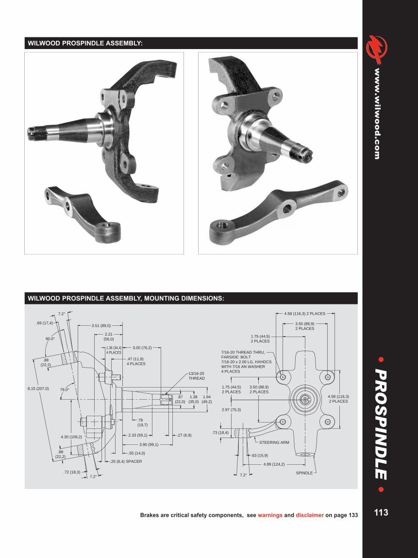
Brakes are critical safety components, see warnings and disclaimer on page 133
www.wilw
ood.com
113
WILWOOD PROSPINDLE ASSEMBLY:
7.2°
7.2°
90.0°
79.0°
1.36 (34,4)
4 PLACES
3.00 (76,2)
3.51 (89,0)
2.21
(56,0)
.47 (11,9)
4 PLACES
13/16-20
THREAD
.87
(22,0)
.78
(19,7)
1.38
(35,0)
1.94
(49,2)
8.15 (207,0)
.69 (17,4)
.72 (18,3)
4.30 (109,2) 2.33 (59,1) .27 (6,9)
STEERING ARM
SPINDLE
7/16-20 THREAD THRU,
FARSIDE: BOLT
7/16-20 x 2.00 LG, HXHDCS
WITH 7/16 AN WASHER
4 PLACES
7.2°
1.75 (44,5)
2 PLACES
3.50 (88,9)
2 PLACES
4.58 (116,3) 2 PLACES
4.58 (116,3)
2 PLACES
3.50 (88,9)
2 PLACES
1.75 (44,5)
2 PLACES
2.97 (75,3)
.73 (18,4)
.63 (15,9)
4.89 (124,2)
3.90 (99,1)
.55 (14,0)
.25 (6,4) SPACER
.88
(22,2)
.88
(22,2)
WILWOOD PROSPINDLE ASSEMBLY, MOUNTING DIMENSIONS:
•P
RO
SP
IND
LE
•

WARNING: The user or installer of any product from this catalog must determine its suitability for their intended purpose or application
www.wilwood.com
114
•A
CC
ES
SO
RIE
S•
ACCESSORIES
Wilwood has available a reproduction of the front steer 1971 - 1972 Pinto Rack and Pinion. This rack is an all newunit that weighs only 9.5 pounds, and is dimensionally identical to the original Pinto Rack. Stock mounting locationsand input shaft with the upgrade of over sized rod ends for added strength and reliability make this the popular choicefor racing applications. Add a chromed center tube and polished housing as a standard feature, and there is noreason to choose a used or rebuilt unit.
DESCRIPTION PART NO.Stock Ratio Rack and Pinion 350-2038Replacement Boot Kit (pair) 350-8821
45.7 (1162,0)
16.20 (411,5)
1.35 (34,3) DIA
24.5 (622,0) (TIE ROD PIVOT POINTS)
(4 TURNS LOCK-TO-LOCK,
5.25" STROKE)
2.88
(73,0)
1/2-20 THREAD
BOTH ENDS26 TOOTH SPLINE
PITCH = 48/96
MAJOR DIA = .562 (14,3)
.48 (12,2) DIA
MOUNT HOLE
WILWOOD’S “PINTO” RACK AND PINION:
ORDERING INFORMATION:
Wilwood’s lightweight billet aluminum Quick Release Steering Hub is a reliable and important safety feature for anyrace car. The spring loaded button is non-removable and easy to use. The steel steering shaft adapter fits into aprecision machined hex bore for a close tolerance fit. It is available to fit either a 5/8” or 3/4” shaft and accepts astandard three bolt steering wheel pattern. Specify either machined or satin black anodized finish.
DESCRIPTION PART NO.3/4” shaft, black anodized 270-20165/8” shaft, black anodized 270-2017Replacement 3/4” steel shaft 300-2019Replacement 5/8” steel shaft 300-2020
ORDERING INFORMATION:
QUICK RELEASE STEERING HUB:
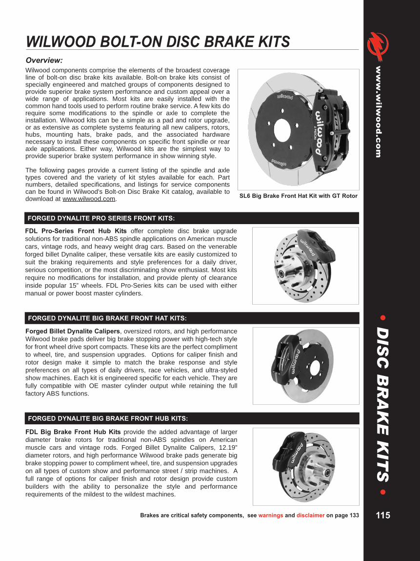
Brakes are critical safety components, see warnings and disclaimer on page 133
www.wilw
ood.com
115
•D
ISC
BR
AK
EK
ITS
•WILWOOD BOLT-ON DISC BRAKE KITSOverview:Wilwood components comprise the elements of the broadest coverageline of bolt-on disc brake kits available. Bolt-on brake kits consist ofspecially engineered and matched groups of components designed toprovide superior brake system performance and custom appeal over awide range of applications. Most kits are easily installed with thecommon hand tools used to perform routine brake service. A few kits dorequire some modifications to the spindle or axle to complete theinstallation. Wilwood kits can be a simple as a pad and rotor upgrade,or as extensive as complete systems featuring all new calipers, rotors,hubs, mounting hats, brake pads, and the associated hardwarenecessary to install these components on specific front spindle or rearaxle applications. Either way, Wilwood kits are the simplest way toprovide superior brake system performance in show winning style.
The following pages provide a current listing of the spindle and axletypes covered and the variety of kit styles available for each. Partnumbers, detailed specifications, and listings for service componentscan be found in Wilwood's Bolt-on Disc Brake Kit catalog, available todownload at www.wilwood.com. SL6 Big Brake Front Hat Kit with GT Rotor
FDL Pro-Series Front Hub Kits offer complete disc brake upgradesolutions for traditional non-ABS spindle applications on American musclecars, vintage rods, and heavy weight drag cars. Based on the venerableforged billet Dynalite caliper, these versatile kits are easily customized tosuit the braking requirements and style preferences for a daily driver,serious competition, or the most discriminating show enthusiast. Most kitsrequire no modifications for installation, and provide plenty of clearanceinside popular 15” wheels. FDL Pro-Series kits can be used with eithermanual or power boost master cylinders.
FORGED DYNALITE PRO SERIES FRONT KITS:
Forged Billet Dynalite Calipers, oversized rotors, and high performanceWilwood brake pads deliver big brake stopping power with high-tech stylefor front wheel drive sport compacts. These kits are the perfect complimentto wheel, tire, and suspension upgrades. Options for caliper finish androtor design make it simple to match the brake response and stylepreferences on all types of daily drivers, race vehicles, and ultra-styledshow machines. Each kit is engineered specific for each vehicle. They arefully compatible with OE master cylinder output while retaining the fullfactory ABS functions.
FORGED DYNALITE BIG BRAKE FRONT HAT KITS:
FDL Big Brake Front Hub Kits provide the added advantage of largerdiameter brake rotors for traditional non-ABS spindles on Americanmuscle cars and vintage rods. Forged Billet Dynalite Calipers, 12.19”diameter rotors, and high performance Wilwood brake pads generate bigbrake stopping power to compliment wheel, tire, and suspension upgradeson all types of custom show and performance street / strip machines. Afull range of options for caliper finish and rotor design provide custombuilders with the ability to personalize the style and performancerequirements of the mildest to the wildest machines.
FORGED DYNALITE BIG BRAKE FRONT HUB KITS:
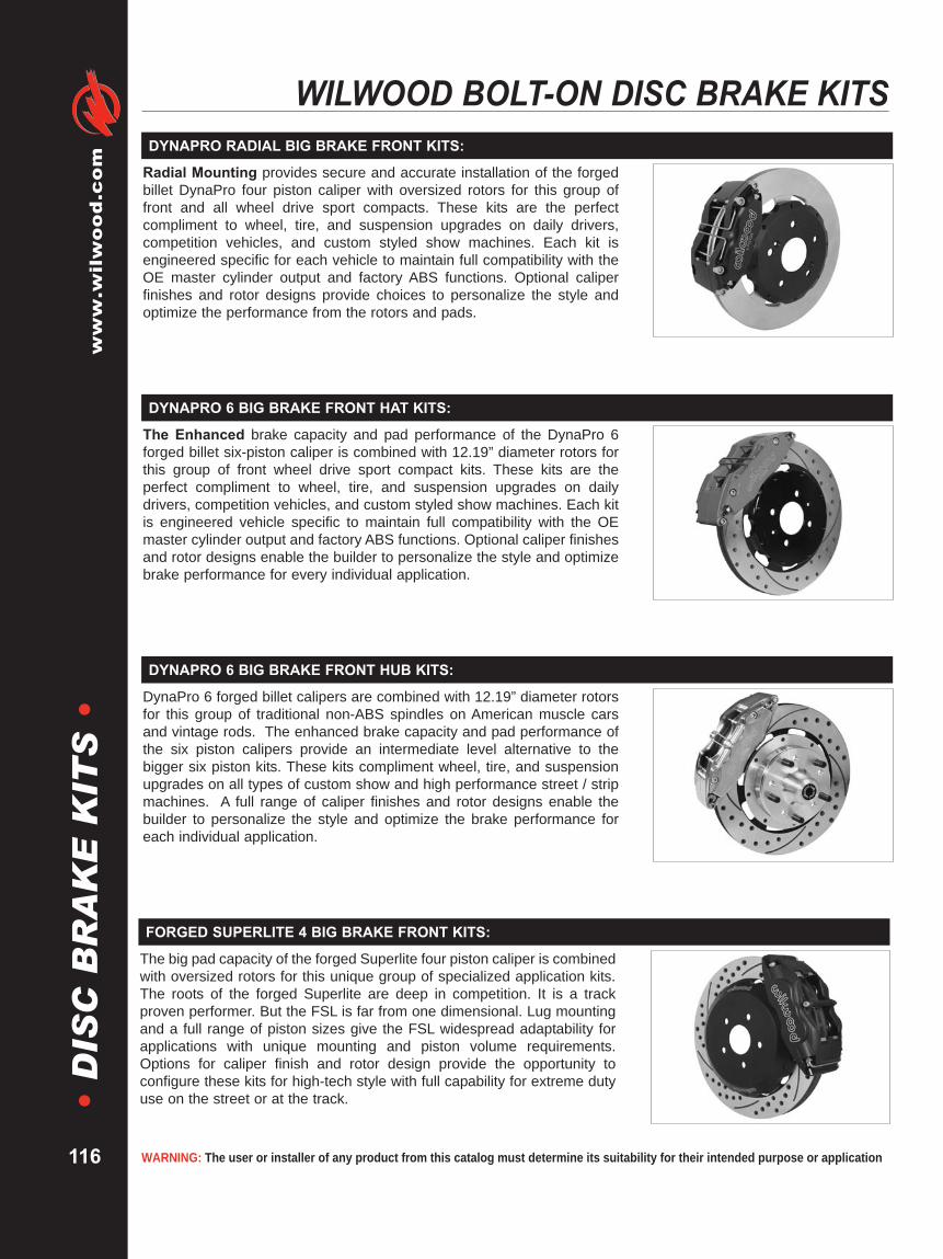
WARNING: The user or installer of any product from this catalog must determine its suitability for their intended purpose or application
www.wilwood.com
116
•D
ISC
BR
AK
EK
ITS
•WILWOOD BOLT-ON DISC BRAKE KITS
Radial Mounting provides secure and accurate installation of the forgedbillet DynaPro four piston caliper with oversized rotors for this group offront and all wheel drive sport compacts. These kits are the perfectcompliment to wheel, tire, and suspension upgrades on daily drivers,competition vehicles, and custom styled show machines. Each kit isengineered specific for each vehicle to maintain full compatibility with theOE master cylinder output and factory ABS functions. Optional caliperfinishes and rotor designs provide choices to personalize the style andoptimize the performance from the rotors and pads.
DYNAPRO RADIAL BIG BRAKE FRONT KITS:
The Enhanced brake capacity and pad performance of the DynaPro 6forged billet six-piston caliper is combined with 12.19” diameter rotors forthis group of front wheel drive sport compact kits. These kits are theperfect compliment to wheel, tire, and suspension upgrades on dailydrivers, competition vehicles, and custom styled show machines. Each kitis engineered vehicle specific to maintain full compatibility with the OEmaster cylinder output and factory ABS functions. Optional caliper finishesand rotor designs enable the builder to personalize the style and optimizebrake performance for every individual application.
DYNAPRO 6 BIG BRAKE FRONT HAT KITS:
DynaPro 6 forged billet calipers are combined with 12.19” diameter rotorsfor this group of traditional non-ABS spindles on American muscle carsand vintage rods. The enhanced brake capacity and pad performance ofthe six piston calipers provide an intermediate level alternative to thebigger six piston kits. These kits compliment wheel, tire, and suspensionupgrades on all types of custom show and high performance street / stripmachines. A full range of caliper finishes and rotor designs enable thebuilder to personalize the style and optimize the brake performance foreach individual application.
DYNAPRO 6 BIG BRAKE FRONT HUB KITS:
The big pad capacity of the forged Superlite four piston caliper is combinedwith oversized rotors for this unique group of specialized application kits.The roots of the forged Superlite are deep in competition. It is a trackproven performer. But the FSL is far from one dimensional. Lug mountingand a full range of piston sizes give the FSL widespread adaptability forapplications with unique mounting and piston volume requirements.Options for caliper finish and rotor design provide the opportunity toconfigure these kits for high-tech style with full capability for extreme dutyuse on the street or at the track.
FORGED SUPERLITE 4 BIG BRAKE FRONT KITS:

Brakes are critical safety components, see warnings and disclaimer on page 133
www.wilw
ood.com
117
•D
ISC
BR
AK
EK
ITS
•
TC6R calipers are purpose built to provide unsurpassed braking capacityon trucks and SUV’s using 20” and larger wheels and tires. Combining thehigh clamping efficiency of the TC6R caliper with 16” diameter directionalvane rotors and high friction BP-10 compound brake pads, TC6R kitsprovide the braking power necessary to control the higher rotating weightof ultra-sized wheels and tires, especially with high GVW vehicles andvehicles used for towing. TC6R kits are engineer application to be fullycompatible with the OE master cylinder output and retain full function ofthe ABS system.
TC 6R BIG BRAKE FRONT KITS:
SL6 forged billet six-piston calipers with 13”-14” rotors deliver the ultimatecombination for braking power and style in this group of kits engineered fortraditional non-ABS spindles on American muscle cars and vintage rods.Built exclusively for 17” and larger wheels, SL6 kits enhance tire andsuspension upgrades on all types of custom show and high performancedual-purpose street and track machines. A full range of options for caliperfinishes and rotor designs are guaranteed to catch the eye of the mostdiscriminating enthusiast while providing optimized brake performance forevery individual application.
SUPERLITE 6 BIG BRAKE FRONT HUB KITS:
W6AR calipers were designed for the specific purpose of providing bigcapacity braking with large diameter rotors for heavy weight and extremeduty vehicles. For cars, it’s the biggest of the big providing big brakeperformance for show and dual purpose street and track vehicles. Fortrucks and SUV’s, it provides big stopping power for towing, off-road, andenhanced braking with wheel and tire upgrades. Kits listed for specificvehicles are fully compatible with OE master cylinder output and ABSfunction. Direction staggered vane 14.00 - 14.25” rotors provide maximumcooling for sustained high heat durability.
W6AR BIG BRAKE FRONT KITS:
SUPERLITE 6 BIG BRAKE FRONT HAT KITS
The unsurpassed braking capacity of the SL6 forged billet six-pistoncaliper serves as the base of this group of 13”-14” big rotor kits for thesepopular late model vehicles. SL6 kits are engineered application specificfor simplified installation and full compatibility with OE master cylinderoutput and ABS functions where used. Big brake kits provide increasedbrake capacity and complimentary style with wheel, tire, and suspensionupgrades on show cars and high performance street/track machines.Optional caliper finishes and rotor designs simplify personalizing the styleand braking requirements of any application.
FDL Pro-Series rear disc brake kits provide a complete solution forpopular muscle car rear axles on applications where individual wheelparking brake assemblies are not required. Forged billet Dynalite fourpiston calipers, two-piece hat and rotor assemblies, and high friction padsprovide optimized and balanced braking for all types of off-road,competition, and other customized applications. FDL calipers can beoptioned with a full range of finishes to reflect personalized style. Rotorchoices provide options for high-tech show winning style, or heavy weightdurability and cooling capacity for high heat competition.
FORGED DYNALITE PRO SERIES REAR KITS:
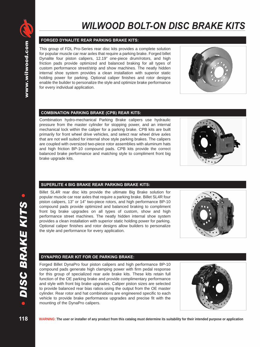
WARNING: The user or installer of any product from this catalog must determine its suitability for their intended purpose or application
www.wilwood.com
118
•D
ISC
BR
AK
EK
ITS
•WILWOOD BOLT-ON DISC BRAKE KITS
FORGED DYNALITE REAR PARKING BRAKE KITS:
This group of FDL Pro-Series rear disc kits provides a complete solutionfor popular muscle car rear axles that require a parking brake. Forged billetDynalite four piston calipers, 12.19” one-piece drum/rotors, and highfriction pads provide optimized and balanced braking for all types ofcustom performance street/strip and show machines. The neatly hiddeninternal shoe system provides a clean installation with superior staticholding power for parking. Optional caliper finishes and rotor designsenable the builder to personalize the style and optimize brake performancefor every individual application.
Billet SL4R rear disc kits provide the ultimate Big Brake solution forpopular muscle car rear axles that require a parking brake. Billet SL4R fourpiston calipers, 13” or 14” two-piece rotors, and high performance BP-10compound pads provide optimized and balanced braking to complimentfront big brake upgrades on all types of custom, show and highperformance street machines. The neatly hidden internal shoe systemprovides a clean installation with superior static holding power for parking.Optional caliper finishes and rotor designs allow builders to personalizethe style and performance for every application.
SUPERLITE 4 BIG BRAKE REAR PARKING BRAKE KITS:
Combination hydro-mechanical Parking Brake calipers use hydraulicpressure from the master cylinder for stopping power, and an internalmechanical lock within the caliper for a parking brake. CPB kits are builtprimarily for front wheel drive vehicles, and select rear wheel drive axlesthat are not well suited for internal shoe style parking brakes. The calipersare coupled with oversized two-piece rotor assemblies with aluminum hatsand high friction BP-10 compound pads. CPB kits provide the correctbalanced brake performance and matching style to compliment front bigbrake upgrade kits.
COMBINATION PARKING BRAKE (CPB) REAR KITS:
Forged Billet DynaPro four piston calipers and high performance BP-10compound pads generate high clamping power with firm pedal responsefor this group of specialized rear axle brake kits. These kits retain fullfunction of the OE parking brake and provide complimentary performanceand style with front big brake upgrades. Caliper piston sizes are selectedto provide balanced rear bias ratios using the output from the OE mastercylinder. Rear rotor and hat combinations are engineered specific to eachvehicle to provide brake performance upgrades and precise fit with themounting of the DynaPro calipers.
DYNAPRO REAR KIT FOR OE PARKING BRAKE:

Brakes are critical safety components, see warnings and disclaimer on page 133
www.wilw
ood.com
119
•D
ISC
BR
AK
EK
ITS
•Billet Superlite 4R four piston calipers are combined with BP-10 compoundpads and 13”-14” rotors in this group of big brake kits for custom highperformance street and show machines. This group of specialized kits forcars, trucks, and SUV’s retain full use of the OE parking brake, mastercylinder output, and ABS where used. SL4R rear kits providecomplimentary style and performance with 13” and larger front brakeupgrades in conjunction with wheel, tire, and suspension upgrades.Optional caliper finishes and rotor designs enable the builder to matchstyle and performance on all applications.
SUPERLITE 4 REAR KIT FOR OE PARKING BRAKE:
W4AR Big Brake rear axle kits replace the factory disc brakes and use theOE parking brake assembly as a compliment to front big brake upgradeson late model trucks and SUV’s. High capacity braking from the W4ARcalipers, BP-10 compound pads, and oversized rotors are matched to theOE master cylinder output, ABS function, and individual vehicle biasrequirements. Enhanced brake performance, increased durability, andhigh-tech style compliment big wheel, tire, and suspension upgrades oncustomized vehicles, tow rigs, and all others with increased brakerequirements from high GVW.
W4AR BIG BRAKE REAR KITS:
TC 6R rear axle disc brake kits with 16” rotors are the ultimate big brakesolution for highly customized and modified trucks or SUV’s with 20” andlarger wheels. TC6R kits replace the factory disc brakes and use the OEparking brake assembly as a compliment to front big brake upgrades. TC6R calipers, BP-10 compound pads, and oversized rotors are matched tothe OE master cylinder output, ABS function, and individual vehicle biasrequirements of each vehicle. These combined enhancements provide thenecessary control over big wheels and tires to provide safe stopping onheavy weight vehicles.
TC 6R BIG BRAKE REAR KITS:
ProMatrix pad, rotor, and flexline upgrade kits offer measurable brakeperformance improvements to racers and enthusiasts using the OE factorybrake calipers. High performance pad compounds are specially selectedto provide increased brake response and higher resistance against fade.Depending on the specific vehicle and parking brake design, one or two-piece rotors are used to provide high temperature durability for the track orhigh-tech style with corrosion resistance for the street. Stainless steelbraided Teflon core flexlines add style, durability, and firmer response withreduced deflection under load.
PROMATRIX FRONT KITS:
ProMatrix pad, rotor, and flexline upgrade kits offer measurable brakeperformance improvements to racers and enthusiasts using the OE factorybrake calipers. High performance pad compounds are specially selectedto provide increased brake response and higher resistance against fade.Depending on the specific vehicle and parking brake design, one or two-piece rotors are used to provide high temperature durability for the track orhigh-tech style with corrosion resistance for the street. Stainless steelbraided Teflon core flexlines add style, durability, and firmer response withreduced deflection under load.
PROMATRIX REAR KITS:

WARNING: The user or installer of any product from this catalog must determine its suitability for their intended purpose or application
www.wilwood.com
120
•D
ISC
BR
AK
EK
ITS
•WILWOOD BOLT-ON DISC BRAKE KITS
The Dynalite Single Floater front drag kit is purpose built for use onlightweight cars using spindle mount brakes on P&S / Anglia stylespindles. The DLSF calipers and lightweight steel rotors combine toprovide excellent static holding power for use as a staging brake or as asupplementary brake on vehicles using parachutes and rear brakes toprovide the majority of the stopping power. Aluminum hats are provided tomount the rotors directly to the spindle mount wheels. A choice of solid orlightweight drilled rotors is offered to provide the lowest possible weight tothe front axle. Mount brackets are included.
DYNALITE SINGLE FLOATER FRONT KITS:
DPS Front Drag kits incorporate the newest DynaPro caliper technology inthis traditional style front brake kit. DPS kits are built for the common frontspindles and aftermarket struts used on four-wheel disc brake drag carsthat weigh in under 2,400 pounds. The billet DPS caliper is a fixed mount,two-piston design that mounts directly to the spindle with a bolt-on bracket.Forged billet, five lug hubs with direct mount lightweight steel rotorscombine to provide consistent braking with an average weight savings of35 pounds over stock drum or disc brakes. Kits include all new hardware,wheel bearings, and seals.
DYNAPRO SINGLE FRONT DRAG KITS:
FDL Front Drag kits are drag racing’s most popular front brake kits. FDLkits are available for the popular muscle car spindles and selectaftermarket front struts used on four-wheel disc cars weighing up to 2,800pounds, or rear drum brake equipped cars weighing up to 2,400 pounds.Forged billet FDL four piston calipers mount directly to the spindle with abolt-on bracket. Forged billet, five lug hubs with direct mount steel rotorscombine to provide an average weight savings of over 30 poundscompared to stock drum or disc brakes. Kits include all new hardware,wheel bearings, seals and extra length lug studs.
FORGED DYNALITE FRONT DRAG KITS:
DPR forged billet, radial mount four piston calipers are used in this selectgroup of drag racing kits. The OE brakes on vehicles originally equippedwith 16” or larger wheels generally do not fit inside the popular 15” dragwheels. Specially designed radial caliper mount brackets bolt directly tothe OE caliper mount, and provide secure and accurate mounting for theDPR caliper. Kits with 3/8” solid steel rotors are recommended for four-wheel disc brake cars up to 2,800 pounds. Kits with .81” HP32 vented ironrotors should be used on cars over 2,800 pound cars, or lighter carsrunning extreme speeds desiring increased rotor durability.
DYNAPRO RADIAL FRONT DRAG KITS:

Brakes are critical safety components, see warnings and disclaimer on page 133
www.wilw
ood.com
121
•D
ISC
BR
AK
EK
ITS
•FDL Rear Drag kits are true bolt-on kits available for all popular muscle carrear axles and aftermarket rears built with custom axle ends. Kits in thisgroup are purpose built for sportsman category door cars and others withfull functional four-wheel disc brakes. Based on the specific style ofhousing end and axle offset, mounting kits securely install the four-pistonforged Dynalite caliper over 3/8” plate steel rotors that are mounted to theaxle with an aluminum hat. Standard kits include solid face rotors, withoptional drilled rotor kits available to further reduce driveline weight inclasses where every weight advantage is necessary.
FORGED DYNALITE REAR DRAG KITS:
Dynamic rotor mounting is especially beneficial to cars that rely heavily onthe rear brakes for stopping, and any other high speed, heavy weight carsthat generate above average rear brake heat. Dynamic mounting usesfloating t-nuts to isolate the different thermal expansion rates between thesteel rotor plate and the aluminum rotor hat. This reduces any tendency forthe rotor to distort and impose any additional stress on the hat.Performance, durability, and the service life of the components are allextended. Additionally, distortion free parts run with lower rolling resistanceto produce higher speeds.
FORGED DYNALITE DYNAMIC REAR DRAG KITS:
Dual caliper kits provide the highest degree of safety, reliability, andunsurpassed stopping power for sportsman category dragsters and othercars that rely on rear brakes only for stopping power. With two calipers ateach wheel, the fluid circuits for each caliper pair can be fully isolated withdual mount or tandem outlet master cylinders. Isolating the fluid circuitsprevents complete system failures in the case of a problem with any singlecaliper or line. Dynamic rotor mounting eliminates distortion caused by thedifferent thermal expansion rates between the steel rotor plate and thealuminum hat.
FORGED DYNALITE DUAL DYNAMIC REAR KITS:
Kits in this competition group are configured for use in production categoryroad racing that allow brake upgrades, but limit modifications to four-pistoncalipers and 12.19” rotors. BSL4R/ST calipers use Thermlock pistons toresist fade and extend service life by reducing the heat transfer into thecaliper from the pads. GT series directional vane rotors provide highcooling efficiency and durability mounted to the hubs with forged aluminumGT hats. Kits also include high temperature race compound pads,stainless steel flexlines, and premium grade hardware for installation in 16”and larger wheels.
SUPERLITE 4 BIG BRAKE FRONT KITS (RACE):

WARNING: The user or installer of any product from this catalog must determine its suitability for their intended purpose or application
www.wilwood.com
122
•D
ISC
BR
AK
EK
ITS
•WILWOOD BOLT-ON DISC BRAKE KITS
Kits in this competition group are configured for use in unrestricted classroad racing with 17” or larger wheels. BSL6R/ST six-piston calipers withThermlock pistons are matched with 12.88” directional vane GTcompetition rotors. These proven winners have delivered championshipperformance in road racings’ most grueling production car categories.Rotors mount to the hubs with forged aluminum hats and radial mountbrackets secure the calipers to the OE location without modification. Kitsalso include high friction race compound pads, premium grade hardware,and stainless steel braided flexlines.
SUPERLITE 6 BIG BRAKE FRONT KITS (RACE):
W6AR/ST six piston radial mount calipers are coupled with the highcooling capacity of 14.25” SV-GT staggered directional vane rotors toprovide the ultimate brake package for unrestricted road race competition.Thermlock pistons in the calipers resist fade and extend service life byreducing the heat transfer from the pads, caliper body, fluid, and seals.Rotors mount to the hubs with forged aluminum hats and radial mountbrackets secure the caliper to the spindle in the OE location withoutmodification. Kits also include high temperature, high friction racecompound pads and all premium grade fasteners.
W6AR BIG BRAKE FRONT KITS (RACE):
Our ProSpindle is specifically designed for use in fabricated A-armsuspensions on kit cars, street rods, drag cars and other custom or raceapplications configured around Pinto/Mustang ll suspension geometry.The 2" dropped spindle pin provides the desired lowered ride heightwithout disturbing the suspension geometry. Complete brake kits andcomponents including forged billet hubs, bearings, seals, locknuts,calipers, brake pads, caliper brackets, and hats or rotor plates to attachoptional rotor styles from 11.00" to 14.00" are all available to configurecustom brake packages and complete the installation.
PROSPINDLE KITS:
BSL4R caliper rear road race kits provide matched performance inconjunction with SL6R and W6AR front race kits on vehicles builtspecifically for competition. BSL4R calipers use stainless steel pistons toretard heat transfer from the pads and high temperature seals for reliabilityin sustained high heat. Radial mount brackets attach the caliper in thestock location. GT series directional vane competition rotors provide highefficiency cooling and mount to the drive axles with forged aluminum hats.Kits also include high temperature, high friction race compound pads andall premium grade fasteners.
SUPERLITE 4R BIG BRAKE REAR KITS (RACE):

Brakes are critical safety components, see warnings and disclaimer on page 133
www.wilw
ood.com
123
•D
ISC
BR
AK
EK
ITS
•BRAKE KIT INDEX BY FITMENT CODE - FRONT APPLICATIONS:
Pg 39 Pg 38 Pg 46 Pg 36 Pg 37 Pg 35 Pg 33 Pg 34 Pg 32 Pg 30 Pg 31 Pg 29 Pg 48 Pg 49a Pg 47 Pg 43 Pg 45
SL4 B
B Rea
r OE P
-Brak
e
SL4 B
B Rea
r P-B
rake K
it
TC6R
BBRe
arKi
t
CDR01
FDR01FDR02
FDR03
ProM
atrix
Fron
t Kit
D8-4
Fron
t Cali
per K
it
BM02
FD12
FDL P
roSe
ries F
ront K
it
AF01
AF03
CD01CD02CD03CD05CD06CD09
FD01
FD03FD05
FD08
FD11
GM01GM02GM03GM04GM05
GM09GM10
FDL B
BFr
ont H
ubKi
t
AF04AF05
CD01
FD01FD02FD03
GM01GM02
GM04
GM09
FDL B
BFr
ont H
atKi
t
CD10
DPR
BBFr
ont K
itBM01
DP6 B
BFr
ont H
ubKi
t
CD01
FD02FD03
GM01GM02
GM09
DP6 B
BFr
ont H
atKi
t
FSL4
BBFr
ont K
it
FD06FD07
SL6 B
BFr
ont H
ubKi
t
AF06
AF09
CD01
FD01FD02
FD06FD07FD08
GM01GM02
GM04
SL6 B
BFr
ont H
atKi
t
BM02
FD09FD10
GM06GM07
FD10
W4AR
BBRe
arKi
t
W6AR
BBFr
ont K
it
TC6R
BBFr
ont K
it
FT01
Fitm
entN
umbe
r
AF01AF02AF03AF04AF05AF06AF08AF09
AFR01BM01BM02
BMR02CD01CD02CD03CD05CD06CD09CD10
CDR01FD01FD02FD03FD05FD06FD07FD08FD09FD10FD11FD12
FDR01FDR02FDR03FDR04FDR05FT01GM01GM02GM03GM04GM05GM06GM07GM08GM09GM10
Street Performance • Street Performance • Street Performance
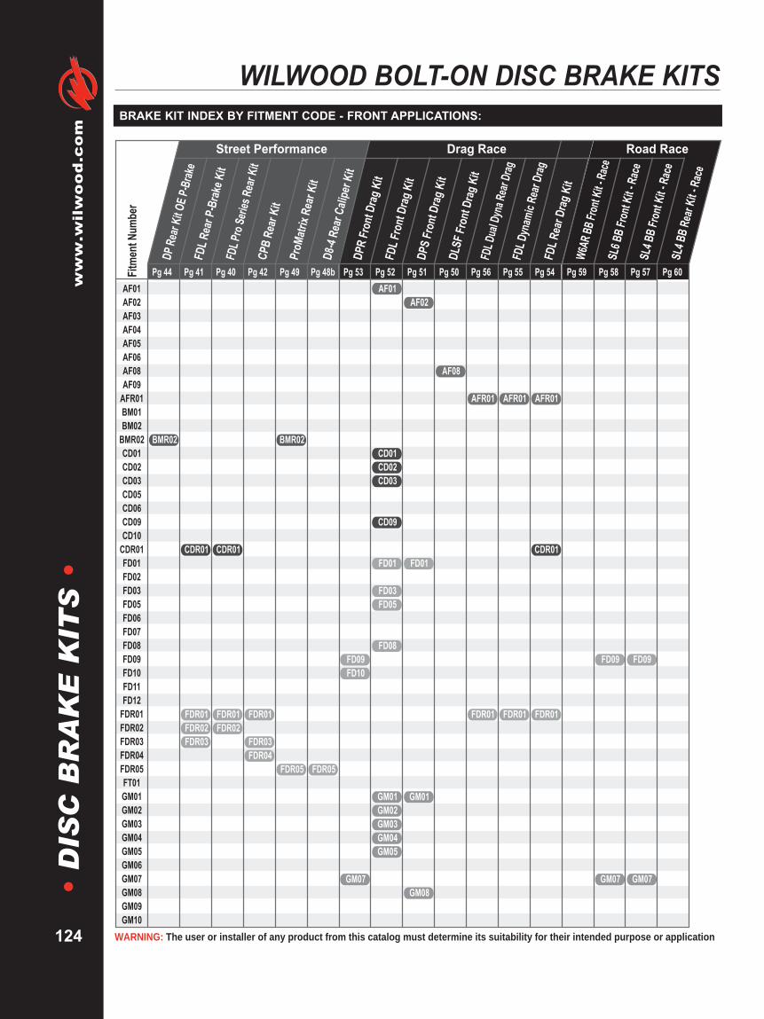
WARNING: The user or installer of any product from this catalog must determine its suitability for their intended purpose or application
www.wilwood.com
124
•D
ISC
BR
AK
EK
ITS
•WILWOOD BOLT-ON DISC BRAKE KITS
BRAKE KIT INDEX BY FITMENT CODE - FRONT APPLICATIONS:
Pg 44 Pg 41 Pg 40 Pg 42 Pg 49 Pg 53 Pg 52 Pg 51 Pg 50 Pg 56 Pg 55 Pg 54 Pg 59 Pg 58 Pg 57 Pg 60Fitm
entN
umbe
r
SL4 B
BRe
arKi
t -Ra
ce
SL4 B
BFr
ont K
it -Ra
ceFD09
GM07
SL6 B
BFr
ont K
it -Ra
ce
FD09
GM07
W6AR
BBFro
ntKit
- Rac
e
FDL R
ear D
rag K
it
AFR01
CDR01
FDR01
FDL D
ynam
icRe
arDr
ag
AFR01
FDR01
FDL D
ual D
yna R
ear D
rag
AFR01
FDR01
DLSF
Fron
t Dra
g Kit
AF08
DPS
Fron
t Dra
g Kit
AF02
FD01
GM01
GM08
FDL F
ront
Drag
Kit
AF01
CD01CD02CD03
CD09
FD01
FD03FD05
FD08
GM01GM02GM03GM04GM05
DPR
Fron
t Dra
g Kit
FD09FD10
GM07
ProM
atrix
Rear
Kit
Pg 48b
D8-4
Rear
Calip
erKi
t
BMR02
FDR05 FDR05
CPB
Rear
Kit
FDR01
FDR03FDR04
FDL P
roSe
ries R
ear K
it
CDR01
FDR01FDR02
FDL R
ear P
-Bra
keKi
t
CDR01
FDR01FDR02FDR03
DPRe
arKi
t OE P
-Brak
e
BMR02
AF01AF02AF03AF04AF05AF06AF08AF09
AFR01BM01BM02
BMR02CD01CD02CD03CD05CD06CD09CD10
CDR01FD01FD02FD03FD05FD06FD07FD08FD09FD10FD11FD12
FDR01FDR02FDR03FDR04FDR05FT01GM01GM02GM03GM04GM05GM06GM07GM08GM09GM10
Drag Race Road RaceStreet Performance

Brakes are critical safety components, see warnings and disclaimer on page 133
www.wilw
ood.com
125
•D
ISC
BR
AK
EK
ITS
•BRAKE KIT INDEX BY FITMENT CODE - FRONT APPLICATIONS:
Pg 39 Pg 38 Pg 46 Pg 36 Pg 37 Pg 35 Pg 33 Pg 34 Pg 32 Pg 30 Pg 31 Pg 29 Pg 48 Pg 47 Pg 43 Pg 45
SL4 B
B Rea
r OE P
-Brak
e
SL4 B
B Rea
r P-B
rake K
it
TC6R
BBRe
arKi
t
GMR03
GMR14GMR15
GTR01GTR02
GMR01
GTR05
GTR03GTR04
ProM
atrix
Fron
t Kit
Pg 49a
D8-4
Fron
t Cali
per K
it
GM12
GM18
MT04
GM15
FDL P
roSe
ries F
ront K
it
WW01
FDL B
BFr
ont H
ubKi
t
WW01
FDL B
BFr
ont H
atKi
t
HN01HN02HN03
MT01
DPR
BBFr
ont K
it
GM16
MT02
SU01
VW01
DP6 B
BFr
ont H
ubKi
t
WW01
DP6 B
BFr
ont H
atKi
t
HN02
FSL4
BBFr
ont K
it
NS02
SC01SC02SP01
SL6 B
BFr
ont H
ubKi
t
WW01
SL6 B
BFr
ont H
atKi
t
GM11GM12GM13
GM15
GM17
HN04
MT03
NS01
SU01
TY01
W4A
RBB
Rear
Kit
GTR01GTR02
W6A
RBB
Fron
t Kit
GM14
GT01
WW01
TC6R
BBFr
ont K
it
GT01GT02
GM11GM12GM13GM14GM15GM16GM17GM18
GMR01GMR02GMR03GMR11GMR12GMR14GMR15GMR17GT01GT02
GTR01GTR02GTR03GTR04GTR05HN01HN02HN03HN04
HNR01HNR02HNR03HNR04MT01MT02MT03MT04
MTR03NS01NS02
NSR01SC01SC02SP01SU01
SUR01TY01VW01WW01
Street Performance • Street Performance • Street Performance
Fitm
entN
umbe
r

WARNING: The user or installer of any product from this catalog must determine its suitability for their intended purpose or application
www.wilwood.com
126
•D
ISC
BR
AK
EK
ITS
•WILWOOD BOLT-ON DISC BRAKE KITS
BRAKE KIT INDEX BY FITMENT CODE - FRONT APPLICATIONS:
Pg 44 Pg 41 Pg 40 Pg 42 Pg 49 Pg 53 Pg 52 Pg 51 Pg 50 Pg 56 Pg 55 Pg 54 Pg 59 Pg 58 Pg 57 Pg 60
SL4 B
BRe
arKi
t -Ra
ce
SL4 B
BFr
ont K
it -Ra
ce
SL6 B
BFr
ont K
it -Ra
ce
W6AR
BBFro
ntKit
- Rac
e
FDL R
ear D
rag K
it
FDL D
ynam
icRe
arDr
ag
FDL D
ual D
yna R
ear D
rag
DLSF
Fron
t Dra
g Kit
DPS
Fron
t Dra
g Kit
FDL F
ront
Drag
Kit
GMR14
GM14
GMR01GMR01GMR01
HN02
DPR
Fron
t Dra
g Kit
ProM
atrix
Rear
Kit
Pg 49b
D8-4
Rear
Calip
erKi
t
GMR11GMR12
GMR15
CPB
Rear
Kit
HNR01HNR02HNR03HNR04
FDL P
roSe
ries R
ear K
it
GMR01
FDL R
ear P
-Bra
keKi
t
GMR01GMR02
GTR05
DPRe
arOE
P-Br
ake
GMR17
MTR03
NSR01
SUR01
GM11GM12GM13GM14GM15GM16GM17GM18
GMR01GMR02GMR03GMR11GMR12GMR14GMR15GMR17GT01GT02
GTR01GTR02GTR03GTR04GTR05HN01HN02HN03HN04
HNR01HNR02HNR03HNR04MT01MT02MT03MT04
MTR03NS01NS02
NSR01SC01SC02SP01SU01
SUR01TY01VW01WW01
Drag Race Road RaceStreet PerformanceFi
tmen
tNum
ber

Brakes are critical safety components, see warnings and disclaimer on page 133
www.wilw
ood.com
127
•D
ISC
BR
AK
EK
ITS
•BRAKE KIT INDEX BY FITMENT CODE - REAR KIT BY OFFSET:
FDL R
ear D
ragKi
t
FDL D
ynam
icRe
arDr
ag
FDL D
ual D
yna R
ear D
rag
CPB
Rear
Kit
FDL P
roSe
ries R
ear K
it
FDL R
ear P
-Brak
e Kit
SL4 B
BRe
arP-
Brak
e Kit
FitmentNumber
AxleOffsetAxle Flange Pg 43 Pg 41 Pg 40 Pg 42 Pg 56 Pg 55 Pg 54Notes
AFR01AFR01CDR01CDR01CDR01CDR01FDR01FDR01FDR01FDR01FDR01FDR01FDR01FDR01FDR01FDR01FDR02FDR02FDR03FDR04GMR01GMR01GMR01GMR01GMR01GMR01GMR01GMR01GMR01GMR01GMR01GMR03GTR05
Green (RP400)Green w/snap ringGreen w/snap ringGreen (RP400)
Currie
Currie
140-9222 (58)
140-9217
140-9218140-9219140-10012 (51)
140-9220140-9216140-9223
140-9221
140-9315 (40)140-9213
140-9215
140-9224
140-10093
140-7144 (58)140-10767
140-7139140-7142 (32)140-9791 (66)
140-7582140-7140140-9560 (40)140-7150 (32)
140-7143140-7146
140-9228
140-7149140-7141
140-7578
140-7147
140-10094
140-2117 (57)140-5591 (58)
140-2116 (57)140-2115140-3722 (32)
140-2114
140-2118
140-9282140-2113140-3018140-2783 (61)
140-2112140-5236 (50)
140-5746
140-2111
140-7148
140-10329
140-10159140-10158
140-5366140-5369 (60)
140-5367
140-5365140-5368 (60)
140-7668140-7670 (60)
140-7696
140-7667140-7669 (60)
140-0265140-5348 (60)140-0260 (57)140-5255 (58)140-8853
140-0261140-3694 (32)140-3623
140-2119
140-0262
140-0263140-4545 (50)
140-5771140-5745 (60)
140-0264140-5349 (60)
2.812.812.362.362.502.722.362.362.502.542.362.502.502.502.502.662.502.502.663.252.752.812.912.912.812.912.912.812.812.912.912.752.42
Mark WilliamsMark WilliamsMopar/DanaMopar/DanaMopar/DanaMopar/DanaBig FordBig FordBig FordBig FordBig Ford New StyleBig Ford New StyleBig Ford New StyleBig Ford New StyleSmall FordSmall Ford8.8 Ford8.8 FordMustang 05-up8.8 Ford 94-0412 Bolt12 Bolt12 Bolt12 Bolt C-Clip Eliminator12 Bolt Special12 Bolt Special12 Bolt SpecialOlds/PontiacOlds/PontiacOlds/PontiacOlds/Pontiac12 Bolt LateLarge Chevy C10

WARNING: The user or installer of any product from this catalog must determine its suitability for their intended purpose or application
www.wilwood.com
128
•T
RO
UB
LE
SH
OO
TIN
G•
TROUBLE SHOOTING
SYMPTOM
LOSE YOURPEDAL DURINGRACE
BRAKE DRAG
CAR WILL NOTSTOP
HAVE TO PUSHHARD ON PEDAL
CAUSE
Fluid boiling due to wet fluid or foot drag.
Undersize brake system.
Wrong size residual pressure valve.
Incorrect or faulty master cylinder.
Leak in caliper or hydraulic lines.
Inadequate ducting.
Pedal linkage failure.
Excessive spindle deflection in corners.
Bad master cylinder.
Incorrect residual pressure valve.
Rotors warped.
Calipers not square to rotor.
Tapered brake pads.
M/C has internal residual pressure.
Glazed pads and/or rotors.
Too large of a master cylinder.
Not enough pedal ratio.
SOLUTION
Flush out entire system with fresh WilwoodHi-Temp° 570 racing brake fluid. Installdashboard brake light reminder.
Refer to the caliper portion of the catalog to selectthe correct caliper/rotor combination for yourapplication.
Use no larger than 2 lb residual pressure valve.
Repair or replace master cylinder.
Check for leaks in caliper and (replace) lines.
Reposition air ducts to center of rotor and caliper.(refer to Wilwood air duct technical sheet)
Check pedal assembly.
Check spindles for warpage. Install 2 lb residualpressure valve.
Switch or replace master cylinder.
Use no larger than 2 lb residual pressure valve.
Replace rotors.
Re-align brackets or shim calipers.
Replace pads, check caliper alignment to rotor.
Remove residual pressure valve.
Grind and/or sand glaze from rotors.
See master cylinder section of catalog to select thecorrect size unit for your application.
Increase pedal ratio, see pedal section of catalog.
This table lists some of the most common items than can signal problems with your brake system. Please consultthis table before calling Wilwood. However, if your problem is not found here, or the solution given does not solvethe problem, please do not hesitate to contact your Wilwood technical advisor for assistance.
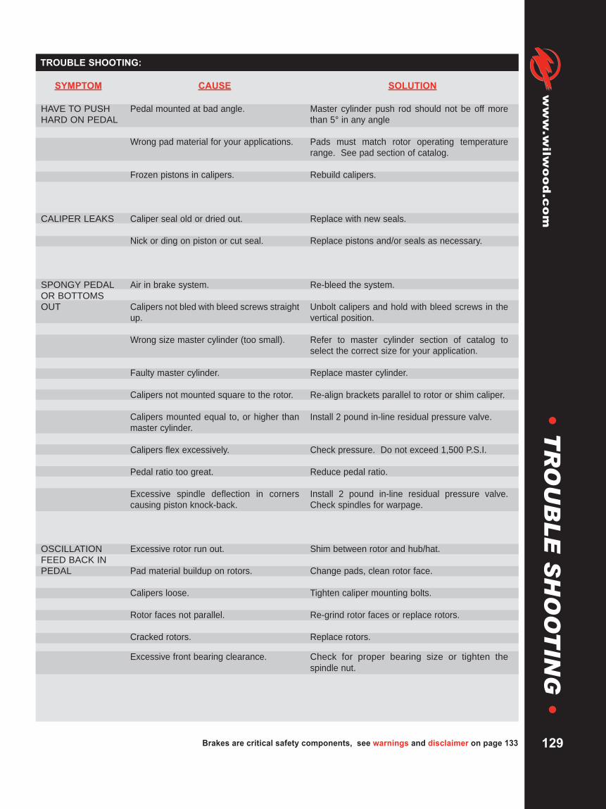
HAVE TO PUSHHARD ON PEDAL
CALIPER LEAKS
SPONGY PEDALOR BOTTOMSOUT
OSCILLATIONFEED BACK INPEDAL
SYMPTOM CAUSE SOLUTION
Pedal mounted at bad angle.
Wrong pad material for your applications.
Frozen pistons in calipers.
Caliper seal old or dried out.
Nick or ding on piston or cut seal.
Air in brake system.
Calipers not bled with bleed screws straightup.
Wrong size master cylinder (too small).
Faulty master cylinder.
Calipers not mounted square to the rotor.
Calipers mounted equal to, or higher thanmaster cylinder.
Calipers flex excessively.
Pedal ratio too great.
Excessive spindle deflection in cornerscausing piston knock-back.
Excessive rotor run out.
Pad material buildup on rotors.
Calipers loose.
Rotor faces not parallel.
Cracked rotors.
Excessive front bearing clearance.
Master cylinder push rod should not be off morethan 5° in any angle
Pads must match rotor operating temperaturerange. See pad section of catalog.
Rebuild calipers.
Replace with new seals.
Replace pistons and/or seals as necessary.
Re-bleed the system.
Unbolt calipers and hold with bleed screws in thevertical position.
Refer to master cylinder section of catalog toselect the correct size for your application.
Replace master cylinder.
Re-align brackets parallel to rotor or shim caliper.
Install 2 pound in-line residual pressure valve.
Check pressure. Do not exceed 1,500 P.S.I.
Reduce pedal ratio.
Install 2 pound in-line residual pressure valve.Check spindles for warpage.
Shim between rotor and hub/hat.
Change pads, clean rotor face.
Tighten caliper mounting bolts.
Re-grind rotor faces or replace rotors.
Replace rotors.
Check for proper bearing size or tighten thespindle nut.
Brakes are critical safety components, see warnings and disclaimer on page 133
www.wilw
ood.com
129
•T
RO
UB
LE
SH
OO
TIN
G•
TROUBLE SHOOTING:
HAVE TO PUSHHARD ON PEDAL
CALIPER LEAKS
SPONGY PEDALOR BOTTOMSOUT
OSCILLATIONFEED BACK INPEDAL

WARNING: The user or installer of any product from this catalog must determine its suitability for their intended purpose or application
www.wilwood.com
130
•T
EC
HN
ICA
LT
IPS
•TECHNICAL TIPS
Proper air ducting is critical for effective performance of short track stock car disc brake systems. Faster cars,improved tires and better aerodynamics has changed the design requirements for brake ducting. Short tracks andmost road courses require specific air duct considerations to maximize the brake systems effectiveness.
Channeling sufficient air from the front of the car through the front brakes is required to remove the large amounts ofheat generated by severe and prolonged brake use. An efficient air ducting system can prevent brake systemoverheating and greatly improve pad life. As car designs have evolved, the aerodynamics of the car’s front end haschanged, thereby affecting the air flow entering the front air scoops (plenum). Because of this change in air flow, thepositioning of intake plenums should be re-evaluated.
By repositioning the plenum intakes vertically as close as possible to the center of the vehicle, air flow is increased.Vertically placed intakes reduce the unwanted effect of air skimming past the duct openings. Locating the intakeducts closer to the center of the vehicle positions them in a high pressure area resulting in greater intake air flow. Formore information on brake cooling, order Wilwood’s AIR DUCTING for Short Track Stock Car Racing, DS-254.
Due to the extreme operating temperatures of a high performance brake system, standard “off-the-shelf” brake fluidsare not recommended. Of critical importance in determining a fluid’s ability to handle high temperature applicationsare its Dry Boiling Point and Compressibility.
The Dry Boiling Point is the temperature at which a brake fluid will boil in its virgin non-contaminated state. Thehighest temperature Dry Boiling Point available in a DOT 3 fluid is 572° F.
The Wet Boiling Point is the temperature a brake fluid will boil after it has been fully saturated with moisture. TheDOT 3 requirement for wet boiling point is a minimum temperature of 284° F.
There are many ways for moisture to enter your brake system. Condensation from regular use, washing the vehicleand humidity are the most common, with little hope of prevention. Glycol based DOT 3 & 4 fluids are hygroscopic;they absorb brake system moisture, and over time the boiling point is gradually reduced.
Wilwood does not recommend using DOT 5 fluid in any racing applications. DOT 5 fluid is not hygroscopic, so asmoisture enters the system, it is not absorbed by the fluid and results in beads of moisture moving through the brakeline, collecting in the calipers. It is not uncommon to have caliper temperatures exceed 200° F, and at 212° F, thiscollected moisture will boil causing vapor lock and system failure. Additionally, DOT 5 fluid is highly compressibledue to aeration and foaming under normal braking conditions, providing a spongy brake feel. DOT 5 fluid is bestsuited for show car applications where its anti-corrosion and paint friendly characteristics are important.
Whenever you add fresh fluid to your existing system (never mix fluids of different DOT classifications), it immediatelybecomes contaminated, lowering the boiling point of the new fluid. For maximum performance, start with the highestDry Boiling Point available (try Wilwood’s Hi-Temp° 570 Racing Brake Fluid), flush the system completely and flushit regularly, especially after severe temperatures have been experienced.
When bleeding the brakes, make sure the bleed screws on the calipers are pointing straight up so there is nopossibility of air bubbles getting trapped. If the calipers are mounted on an angle, you will need to unbolt one earfrom the bracket. Pivot the caliper so it points straight up and place a spacer between the pads to prevent the pistonsfrom coming out of the housing.
BRAKE FLUID:
BRAKE SYSTEM COOLING:
CALIPER BLEED SCREWS POINTING UP:
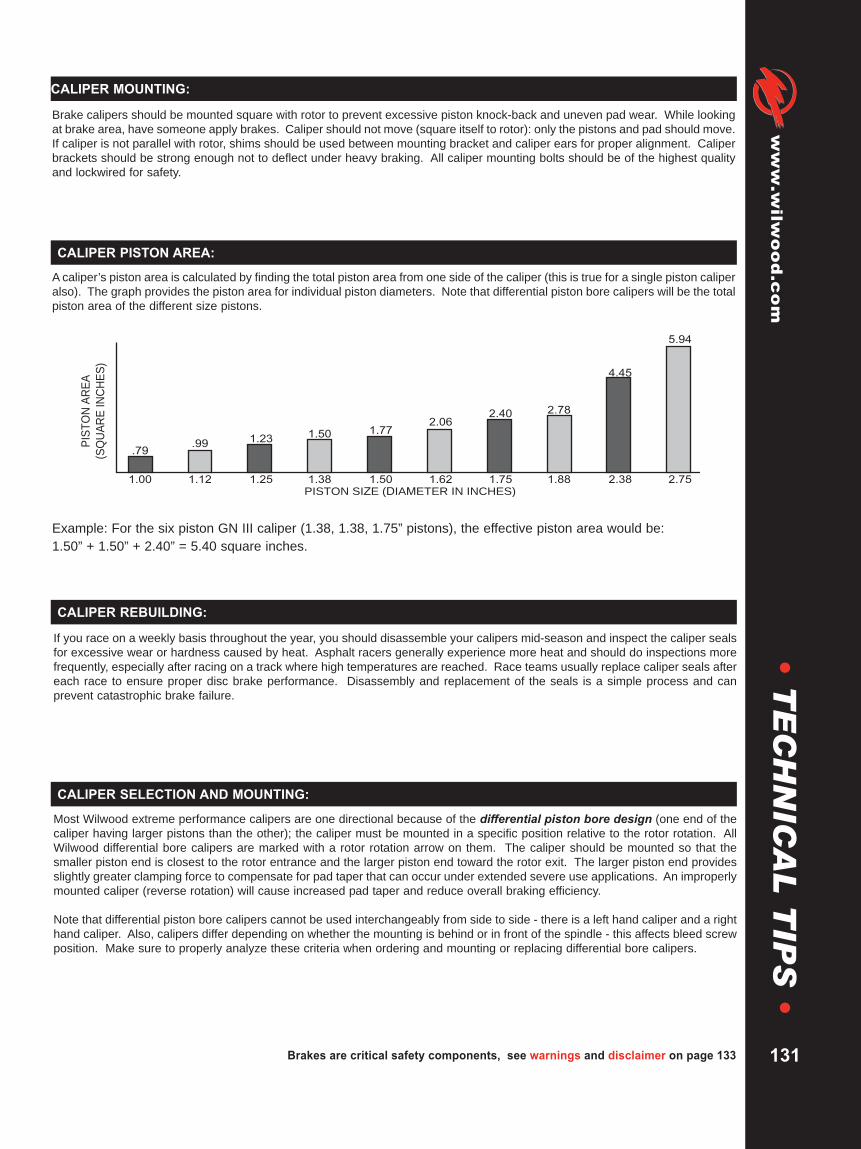
Brakes are critical safety components, see warnings and disclaimer on page 133
www.wilw
ood.com
131
•T
EC
HN
ICA
LT
IPS
•CALIPER MOUNTING:
Brake calipers should be mounted square with rotor to prevent excessive piston knock-back and uneven pad wear. While lookingat brake area, have someone apply brakes. Caliper should not move (square itself to rotor): only the pistons and pad should move.If caliper is not parallel with rotor, shims should be used between mounting bracket and caliper ears for proper alignment. Caliperbrackets should be strong enough not to deflect under heavy braking. All caliper mounting bolts should be of the highest qualityand lockwired for safety.
If you race on a weekly basis throughout the year, you should disassemble your calipers mid-season and inspect the caliper sealsfor excessive wear or hardness caused by heat. Asphalt racers generally experience more heat and should do inspections morefrequently, especially after racing on a track where high temperatures are reached. Race teams usually replace caliper seals aftereach race to ensure proper disc brake performance. Disassembly and replacement of the seals is a simple process and canprevent catastrophic brake failure.
A caliper’s piston area is calculated by finding the total piston area from one side of the caliper (this is true for a single piston caliperalso). The graph provides the piston area for individual piston diameters. Note that differential piston bore calipers will be the totalpiston area of the different size pistons.
Example: For the six piston GN III caliper (1.38, 1.38, 1.75” pistons), the effective piston area would be:1.50” + 1.50” + 2.40” = 5.40 square inches.
PIS
TO
NA
RE
A
(SQ
UA
RE
INC
HE
S)
1.00
.79
1.12
.99
1.25
1.23
1.38
1.50
1.50
1.77
1.62
2.06
1.75
2.40
1.88
2.78
2.38
4.45
2.75
5.94
PISTON SIZE (DIAMETER IN INCHES)
Most Wilwood extreme performance calipers are one directional because of the differential piston bore design (one end of thecaliper having larger pistons than the other); the caliper must be mounted in a specific position relative to the rotor rotation. AllWilwood differential bore calipers are marked with a rotor rotation arrow on them. The caliper should be mounted so that thesmaller piston end is closest to the rotor entrance and the larger piston end toward the rotor exit. The larger piston end providesslightly greater clamping force to compensate for pad taper that can occur under extended severe use applications. An improperlymounted caliper (reverse rotation) will cause increased pad taper and reduce overall braking efficiency.
Note that differential piston bore calipers cannot be used interchangeably from side to side - there is a left hand caliper and a righthand caliper. Also, calipers differ depending on whether the mounting is behind or in front of the spindle - this affects bleed screwposition. Make sure to properly analyze these criteria when ordering and mounting or replacing differential bore calipers.
CALIPER PISTON AREA:
CALIPER REBUILDING:
CALIPER SELECTION AND MOUNTING:
WARNING: The user or installer of any product from this catalog must determine its suitability for their intended purpose or application
www.wilwood.com
132
•T
EC
HN
ICA
LT
IPS
•TECHNICAL TIPS
When changing brake calipers, it is a good idea to put in fresh fluid. Unlike all other racing applications mentionedin this catalog, Harley-Davidson® Motorcycles use DOT 5 silicon fluid, which has different characteristicsthan DOT 3, DOT 4, or DOT 5.1 Racing Brake Fluid. The primary reason for using DOT 5 fluid with street bikes isto prevent paint damage should brake fluid be spilled or dripped on fenders, gas tanks, etc. DOT 3, 4, or 5.1 RacingBrake Fluid is superior for high performance racing applications. Wilwood racing and performance calipers will workwith either DOT 3, 4, 5, or 5.1 brake fluid, but it should be emphasized that DOT 5 silicon fluid should NEVER bemixed with DOT 3, 4, or 5.1 fluids. Replace your factory DOT 5 silicon brake fluid with another DOT 5 type, or flushout your brake system and replace it with a high performance DOT 3, 4, or 5.1 fluid, taking care not to spill on anypaint surfaces and taking note of proper use instructions.
Proper selection of a brake pad compound is critical to disc brake system performance. Each material has specific torque andwear characteristics relative to its operating temperature. Track conditions and driving style can also influence pad requirements.For best performance, final selection of pad material often requires evaluation at the track over a range of actual race conditions.Please reference the Wilwood Brake Pad Catalog, or pages 56 - 65 in this Technical Manual for descriptions of the variouscompounds available. You may also contact the Wilwood Technical Department for recommendations.
Finding areas to cut weight is becoming increasingly more difficult, so if you are evaluating whether or not to takeweight out of your brake system, here is something to keep in mind:
A caliper’s size (and weight) is largely affected by the size of the brake pad it needs to hold. If you can go to a smallerbrake pad (without running out of pad before you run out of event) then a smaller, lighter caliper may be for you. Forexample, if your pads last about 10 races, consider going to a smaller pad that will require changing a bit morefrequently. Remember, if you go to a smaller caliper, you won’t affect stopping performance provided piston sizes staythe same. Also keep in mind that pad wear is heavily dependent on operating temperature, so if you are going toexperiment with downsizing, make sure you have adequate cooling.
As long as your pads are wearing evenly across the pad surface, the pads can be used almost down to the backingplate. Spacer plates may be added behind the pad backing plate as it wears so the caliper pistons will not have tobe exposed to the abusive track dirt and grit.
A regular check of the brake pads for excessive wear and taper is necessary to ensure proper disc brake performance.
MOTORCYCLE BRAKE FLUID:
PAD SELECTION:
PAD WEAR:
WEIGHT REDUCTION:

Brakes are critical safety components, see warnings and disclaimer on page 133
www.wilw
ood.com
133
•D
ISC
LA
IME
RO
FW
AR
RA
NT
Y•
WARNINGS:
Purchasers recognize and understand that racing parts and equipment, such as disc brakes, hubs, etc. and all parts, inventoryand services manufactured and/or sold by Wilwood Engineering, Inc. are exposed to many and varied conditions due to themanner in which they are installed and used. Purchasers and Wilwood Engineering, Inc. consciously desire to make their ownbargain, irrespective of any court decision and purchasers agree upon good faith and in consideration for being allowed topurchase from Wilwood Engineering, Inc. said parts or services. Purchasers expressly acknowledge and understand that WilwoodEngineering, Inc. does not make any affirmation of fact or promise to purchaser, which relates to said parts, inventory, or servicesthat becomes part of the basis of the bargain between Wilwood Engineering, Inc. and purchasers. Nor does Wilwood Engineering,Inc. make, or cause to be made to purchaser any description of the goods sold to purchaser, nor does Wilwood Engineering, Inc.make, or cause to be made, as part of the basis of the bargain with purchasers, any description or affirmation of fact concerningany sample or model of racing parts, and equipment inventory or service.
As further consideration for purchasers using Wilwood Engineering, Inc. racing parts and equipment any and all inventory andservices, purchasers acknowledge that due to the differing conditions and circumstances under which all equipment and partsare installed and used, purchasers are not relying on Wilwood Engineering, Inc. skill or judgement to select or furnish the properpart or equipment. Purchasers expressly affirm they are relying upon their own skill or judgement to select and purchasesuitable goods.
Wilwood Engineering, Inc. makes no warranties whatsoever, expressed or implied, oral or written, to purchasers. There is nowarranty of merchantability made to purchasers. Wilwood Engineering, Inc. further excludes any implied warranty of fitness withrespect to racing and equipment, any and all inventory and service.
It is expressly understood and agreed between purchasers and Wilwood Engineering, Inc. that as part of the bargain betweenWilwood Engineering, Inc. and purchasers, and in consideration of doing business with each other, all purchasers take, select andpurchase said racing parts, equipment, any and all inventory, or services from Wilwood Engineering, Inc. “as is” and “with all faults”and Wilwood Engineering, Inc. shall always provide purchasers with a full and complete opportunity to examine, at purchasers’leisure and convenience, any racing parts and equipment, any and all inventory, or services when purchasing or contemplatingpurchasing from Wilwood Engineering, Inc.
If, and in the event that purchasers expressly or impliedly cause representations, or statements or affirmations of fact contrary tothis disclaimer of all warranties, expressed or implied, then purchasers agree to indemnify and hold harmless WilwoodEngineering, Inc. in the event of any claim, demand, or legal action against Wilwood Engineering, Inc. by any purchaser.
Purchasers understand and agree that no officer, director, employee, or salesman of Wilwood Engineering, Inc. has any authorityto make any statement contrary to the terms of this agreement. On the contrary, Wilwood Engineering, Inc. disavows anystatement contrary to what is herein above written.
DISCLAIMER OF WARRANTY:
WARNINGIt is the responsibility of the person selecting or installing any brake component or kit to determine the suitability of the component or kit for that particularapplication. If you are not sure how to safely use this brake component or kit, you should not install or use it. Do not assume anything. Improperlyinstalled or maintained brakes are dangerous. If you are not sure, get help or return the product. You may obtain additional information and technicalsupport by calling Wilwood at (805) 388-1188, or visit our web site at www.wilwood.com. Use of Wilwood technical support does not guarantee properinstallation. You, or the person who does the installation must know how to properly use this product. It is not possible over the phone to understandor foresee all the issues that might arise in your installation.
Racing equipment and brakes must be maintained and should be checked regularly for fatigue, damage, and wear.
WARNING - TEST YOUR BRAKESDO NOT DRIVE ON UNTESTED BRAKES • BRAKES MUST BE TESTED AFTER INSTALLATION OR MAINTENANCE
MINIMUM TEST PROCEDURE• Make sure pedal is firm: Hold firm pressure on pedal for several minutes, it should remain in position without sinking. If pedal sinks toward floor,check system for fluid leaks. DO NOT drive vehicle if pedal does not stay firm or can be pushed to the floor with normal pressure.
• At very low speed (2-5 mph) apply brakes hard several times while turning steering from full left to full right, repeat several times. Remove thewheels and check that components are not touching, rubbing, or leaking.
• Carefully examine all brake components, brake lines, and fittings for leaks and interference.• Make sure there is no interference with wheels or suspension components.• Drive vehicle at low speed (15-20 mph) making moderate and hard stops. Brakes should feel normal and positive. Again check for leaks andinterference.
• Always test vehicle in a safe place where there is no danger to (or from) other people or vehicles.• Always wear seat belts and make use of all safety equipment.
