win-rc wall · automatically adjusted for varying wall dimensions. the foundation can consist of a...
TRANSCRIPT

WIN-RC WALL
Bridge Engineering Software and Technology Center Department of Civil and Environmental Engineering University of Maryland College Park, Maryland 20742 October 2007 Documentation No. SUB 03-001

i
RETAINING WALL
* TABLE OF CONTENTS *
1.0 SPECIFICATION OF PROBLEM………………………………1-1
1.1 PROGRAM ABSTRACT…………………………………1-1
1.2 PROGRAM SCOPE………………………………………1-1 2.0 DESCRIPTION OF PROBLEM…………………………………2-1
2.1 GENERAL……………………………………………….. 2-1
2.2 PROGRAM CAPABILITIES……………………………..2-1
a) Lateral Earth Pressure b) Vertical Earth Pressure c) Surcharge d) Stability e) Section Design f) Pile Foundation g) Anchored Wall
3.0 INPUT…………………………………………………………..3-1
3.1 SYSTEM DATA…………………………………………3-1
Data Type 01012 – Project Data Data Type 01022 – Project Data Data Type 01032 – General Programs Options
3.2 WALL CONFIGURATION DATA…………………….3-3
Data Type 01042 – Cantilevered Wall Data Data Type 01052 – Anchored Wall Data Data Type 01062 – Abutment Wall Data
3.3 SOIL DATA…………………………………………….3-7

ii
Data Type 02022 – Soil Data and Configuration
3.4 MATERIAL AND DESIGN DATA…………………….3-9
Data Type 02012 – Material and Design Parameters Data Type 02052 – Unit Price Data
3.5 LOAD DATA……………………………………………3-11
Data Type 02032 – Surcharge Data Data Type 06012 – External Load Data
3.6 PILE DATA……………………………………………..3-15
Data Type 03012 – General Pile Properties
Data Type 03022 – Individual Pile Properties REFERENCES…………………………………………….…..3-19 4.0 OUTPUT………………………………………………………..4-1
4.1 VERIFICATION OF OUTPUT………………………….4-1
4.2 STEM DESIGN…………………………………………..4-1
4.3 STABILITY………………………………………………4-2
4.4 FOUNDATION DESIGNS…………………………….....4-2
4.5 QUANTITIES…………………………………………….4-3 5.0 DIAGNOSTICS………………………………………………….5-1
5.1 GENERAL………………………………………………...5-1
5.2 FATAL ERRORS…………………………………………5-1
5.3 NON-FATAL ERRORS…………………………………..5-1
5.4 DESIGN AND ANALYSIS CHECKS……………………5-1

iii
6.0 EXAMPLE PROBLEMS………………………………………… 6-1
Problem 1 Problem 2 Problem 3 Problem 4 Problem 5 Problem 6
7.0 METHODOLOGY............................................................................7-1
7.1 GENERAL…………………………………………………..7-1
7.2 EARTH PRESSURES………………………………………7-1
A. General B. Lateral Earth Pressure C. Vertical Earth Pressure D. Earth Pressure for Anchored Wall
7.3 SURCHARGE LOADING…………………………………..7-5
A. General B. Lateral Surcharge Load Effects C. Stem Design D. Stability Analysis E. Vertical Surcharge Load Forces
7.4 KEY DEPTH…………………………………………………7-9
A. General B. Sliding Resistance C. Concrete Design D. Design Notes
7.5 STABILITY………………………………………………….7-11
A. General B. Overturning

iv
C. Sliding D. Soil Failure E. Resultant Check
7.6 SELECTION DESIGN………………………………………7-12
A. General B. Concrete Theory C. Stem Design D. Footing Design
7.7 PILE GROUP………………………………………………...7-14
A. General B. Theory C. Design Method
REFERENCES………………………………………………..…….7-16

v
LIST OF TABLES
SECTION 3.0 INPUT TABLE 3.1.1 -- DEFINITION OF OUTPUT LEVELS TABLE 3.1.2 -- DESIGN CODE OPTIONS TABLE 3.1.3 -- RETAINING WALL DESIGN/ANALYSES OPTIONS TABLE 3.1.4 -- KEY CONTROL FOR SPREAD FOOTINGS SECTION 4.0 OUTPUT TABLE 4.2.1 -- DESIGN NOTES FOR STEM TABLE 4.3.1 -- DESIGN NOTES FOR STABILITY ANALYSIS TABLE 4.3.2 -- DESIGN NOTES FOR PILE FOUNDATION TABLE 4.4.1 -- DESIGN NOTES FOR SPREAD FOOTING TABLE 4.4.2 -- DESIGN NOTES FOR PILE CAP TABLE 4.5.1 -- DESIGN NOTES FOR QUANTITIES SECTION 5.0 DIAGNOSTICS TABLE 5.2.1 -- FATAL ERROR DIAGNOSTICS (F) TABLE 5.3.1 -- NON-FATAL ERROR DIAGNOSTICS (C) TABLE 5.4.1 -- DESIGN AND ANALYSIS CHECKS (D) SECTION 6.0 EXAMPLE PROBLEMS TABLE 6.1 -- EXAMPLES PROBLEMS

vi
LIST OF FIGURES
SECTION 3.0 INPUT FIGURE 3.1A Kv AND Kh VALUES FOR GENERAL BACKFILL CONDITIONS FIGURE 3.1B VARIOUS BACKFILL CONFIGURATIONS FIGURE 3.2A Kv VALUES FOR INFINITELY SLOPING BACKFILL FIGURE 3.2B Kh VALUES FOR INFINITELY SLOPING BACKFILL FIGURE 3.3 RANKINE ACTIVE-EARTH-PRESSURE COEFFICIENTS FOR
INFINITELY SLOPING BACKFILL FIGURE 3.4 POINT LOAD SURCHARGE FIGURE 3.5 LINE LOAD SURCHARGE FIGURE 3.6 STRIP LOAD SURCHARGE FIGURE 3.7 UNIFORM LOAD SURCHARGE FIGURE 3.8 CANTILEVER RETAINING WALL AND BACKFILL FIGURE 3.9 SUGGESTED SOIL PARAMETERS FIGURE 3.10 PILE GROUP CONFIGURATION FIGURE 3.11 PASSIVE PRESSURE OPTION FIGURE 3.12 EXTERNAL LOAD DATA SECTION 7.0 METHODOLOGY FIGURE 7.1 HEIGHT OF VERTICAL STRESS PLANE FOR OVERTURNING AND FOOTING DESIGN FIGURE 7.2 HEIGHT OF VERTICAL STRESS PLANE FOR STEM DESIGN FIGURE 7.3 HEIGHT OF VERTICAL STRESS PLANE FOR OVERTURNING AND
FOOTING DESIGN FIGURE 7.4 HEIGHT OF VERTICAL STRESS PLANE FOR STEM DESIGN FIGURE 7.5 HEIGHT OF VERTICAL STRESS PLANE FOR OVERTURNING AND
FOOTING DESIGN FIGURE 7.6 HEIGHT OF VERTICAL STRESS PLANE FOR STEM DESIGN FIGURE 7.7 HORIZONTAL INFLUENCE ON VERTICAL STRESSES DUE TO POINT
LOAD FIGURE 7.8 HORIZONTAL INFLUENCE AT ANY POINT FIGURE 7.9 AREA OF SOIL SURFACE IN WHICH SURCHARGE LOADS ARE
CONSIDERED EFFECTIVE IN PRODUCING LATERAL FORCES ON DESIGN STRIP OF WALL-STEM DESIGN CASE
FIGURE 7.10 VERTICAL PRESSURE EFFECTS FROM SURCHARGE OUTSIDE OF Hs FROM WALL
FIGURE 7.11 VERTICAL PRESSURE EFFECTS FROM SURCHARGE INSIDE IF Hs FROM WALL
FIGURE 7.12 HEIGHT OF VERTICAL STRESS PLANE FOR OVERTURNING AND FOOTING DESIGN
FIGURE 7.13 HEIGHT OF VERTICAL STRESS PLANE FOR STEM DESIGN

1-1
1.0 SPECIFICATION OF PROGRAM 1.1 PROGRAM ABSTRACT
The analysis and design of cantilevered or anchored retaining walls and abutments, cantilevered or anchored, are performed. The program automatically considers active earth pressures and adjusts the coefficients for adjusted wall dimensions, checks stability of the wall with respect to sliding, soil pressure, and overturning, and performs the section design of the stem and footing including the reinforcement. Various options allow for the effects of point or infinite and finite uniform or line surcharge loadings. The effects of infinite or broken backfill cases can be considered and also automatically adjusted for varying wall dimensions. The foundation can consist of a spread footing with an option for a key or a pile group. The pile group analysis can consider the effects of the lateral stability afforded by the subgrade.
1.2 PROGRAM SCOPE
The following are the general features and limitations of the program:
1) Various design specifications have been incorporated into the program. These may be found in TABLE 3.1.2 — DESIGN CODE OPTIONS (see SECTION 3.1).
2) The stem and footing are considered rigid.
3) The number of locations along stem where moments, shears, and section designs are performed; default value can be specified = 10
4) The subgrade for the pile foundation is idealized as being composed of uniform, elastic, isotropic material.
5) The maximum number of piles allowed = 20
6) All piles are considered to be prismatic.
7) Design can be performed on the pile group. The configuration is analyzed as given, and row spacing, batter, toe size, are altered to give maximum representative wall length.
8) The program will compute required steel areas for a given concrete section. In the design
mode, the batter of the stem will be increased, if necessary, and the footing thickness will be increased or decreased for an optimal design. The wall dimensions are checked for overturning, sliding, and soil pressure failure.
9) The wall is idealized as being composed of a configuration which is considered to be
representative of the entire wall. 10) The coefficients which define the active earth condition can be generated either automatically
by the program of input directly. If generated automatically, the Coulomb theory or Rankine

1-2
theory is assumed and the coefficients are automatically adjusted to account for varying heel lengths.
11) In case of inadequate stability against sliding, a key may be considered for both the design
and analysis options.
12) Various surcharge cases can be considered, including: Point loads;
Line loads of a specified or infinite length parallel to stem; Patch loads of a specified length and width;
Uniform loads of a specified width and a specified or infinite length. 13) The maximum number of surcharge cases = 9.
14) The program does not consider axial forces in the concrete design, nor can it account for concentrated horizontal forces such as, for instance, the impact of a truck striking a guardrail which would be mounted on top of the wall.
15) In determining the resistance of a retaining wall to sliding, the benefit of the passive soil
pressure from the soil above the footing bottom is ignored. It is assumed that the soil below the footing bottom is undisturbed. The toe overburden is considered in computing vertical soil pressure. But, to be conservative in case it is excavated, it is recommended that no toe overburden be input into the program.
16) It is assumed that the backfill is a granular soil and is well drained. 17) Multi-level anchors are allowed, constructed either from top down or bottom up
18) The maximum number of levels of anchors = 5
19) External loads are allowed as individual load groups with load code ID designated.
20) The maximum number of external loads = 20

2-1
2.0 DESCRIPTION OF PROGRAM 2.1 GENERAL
This program is intended to accommodate the majority of problems encountered in the analysis and design of retaining wall structures. A variety of geometrical, load, and foundation configurations are available along with numerous design and analysis options. The various options are given below in this section and the detail underlying the theory can be found in SECTION 7.0 — METHODOLOGY.
2.2 PROGRAM CAPABILITIES
a) Lateral Earth Pressures
Lateral earth pressures are given by one of two methods at the option of the user. The first method is to allow the program to generate automatically the coefficients which determine the horizontal earth pressures. If this is done, the Coulomb or the Rankine earth pressure theory is used (see SECTION 7.0 — METHODOLOGY). If the design option is chosen, the coefficients then are updated automatically to reflect the changes in the heel lengths. A limitation associated with this option is that the slope of the backfill is restricted to (Μ - 3.2)o where Μ is the angle of internal friction of the fill material. For slopes greater than (Μ - 3.2)o, the second method of specifying the lateral earth pressures must be used (see SECTION 2.3 — PROGRAM LIMITATIONS). The second input option method requires that values for the horizontal and vertical soil coefficients, KH and KV respectively, be input directly by the user. These may be determined from charts found in Refs. 3.4, 3.5, 3.6, 3.7, 3.9, and 3.10, or by consulting a qualified soils engineer. (See FIGURES 3.1A, 3.1B, 3.2A, 3.2B, and 3.3).
Various backfill configurations are allowed, specifically:
1) Horizontal backfill;
2) A sloping backfill with a drain;
3) A "broken back" backfill with a drain.
These are shown in FIGURE 3.1B, where the lateral earth pressures are computed from the Coulomb or Rankine methods. It should be noted that the sloping and "broken back" backfill need not be treated as a surcharge loading, but is automatically handled by the Coulomb or Rankine theory.
b) Vertical Earth Pressures
The vertical component on the wall due to earth pressure is based upon the same

2-2
methods utilized in determining the lateral earth pressures (see SECTION 2.2a above). If the automatic option is chosen (where Kv and KH are obtained via the Rankine theory) then the user may specify the percentage of the vertical component of the active earth coefficient to be used. The lower the percentage (it may be specified as zero), the more conservative the design will be with respect to sliding and overturning moments.
c) Surcharge
Four types of surcharge loadings may be specified: TYPE 1: Point loads. TYPE 2: Line loads of infinite or specified length parallel to the stem. TYPE 3: Patch loads of infinite or specified length and width.
TYPE 4: Uniform loads of infinite length and width. Such loads are external loads (see FIGURES 3.4, 3.5, 3.6, and 3.7), which are placed behind the wall and need not include irregular soil conditions such as sloping backfill.
d) Stability
Three stability checks are made within the program and are described as follows:
Overturning — Equilibrium of the wall against overturning is checked automatically within the program. This check considers the effect of the full horizontal earth pressures and percentages (specified by the user) of the vertical component of the earth pressure and surcharges. Special options such as factors of safety against overturning and the location of the resultant force due to soil pressure may also be input.
Sliding — Equilibrium of the wall against sliding due to the horizontal
earth pressures of the backfill is checked automatically. The user may specify percentages of the vertical components due to earth and surcharge loadings which, when taken times the coefficient of friction, resist sliding. The user may also specify a key to be placed at any location in a spread footing.
Soil Pressure The ability of the soil to support a spread footing is
checked automatically for adequacy within the program. The effects of dead loads, forces due to the backfill, and surcharge loadings are all considered when calculating the maximum soil pressures.

2-3
e) Section Design
For the analysis option, the required steel areas and development lengths are given for the stem and footing sections input. For the design option, the areas of tension and compression reinforcement, the required bar development length, and the rebar stresses are given for the designed stem sections. The footing thickness is optimized, and the rear batter of the stem is increased, if necessary, in the design option.
For both design and analysis, the maximum areas of compressive reinforcement are checked for all sections including at the haunch (if any) as well as at the base of the stem.
f) Pile Foundation
The program performs an analysis of a pile group foundation. The method used in the analysis is three-dimensional matrix method where the piles are idealized as beams on elastic foundations; the user may specify subgrade interaction as an option. The method of analysis is general in that many pile configuration types are allowed. These are as follows:
The piles can be either of the bearing or friction types;
The piles may be considered hinged or fixed to the footing;
A subgrade modulus can be neglected or specified if the soil and design
conditions warrant. Output from the analysis includes:
Axial force in the pile;
Two components of shear normal to the axis of the pile;
Two components of bending moment.
g) Anchored Wall
The program has the option to perform an analysis and design of an anchored wall. For anchored walls with one level of anchors, the earth pressure may be assumed to be linearly proportional to depth. For anchored walls with two or more levels of anchors, the earth pressure may be assumed constant with depth. For walls constructed from the top down, the earth pressure is constant. For walls constructed in fill from the bottom up, the total magnitude of the uniform, rectangular distribution may be assumed to be equal to 130% of a triangular distribution for non-anchored walls. The surcharge loads are the same as the

2-4
loads described previously under the same title. Prestressed anchors are designed to resist pullout of the bonded length in soil or rock. The facings are designed assuming they are simply supported between elements. Vertical wall elements are designed to resist all horizontal earth pressure, surcharge, water pressure, and anchor loads.

3-1
3.0 INPUT All numerical input must have a decimal point except those designated as integers which must be right-justified or alphanumeric. 3.1 SYSTEM DATA
Data Type 01012, 01022 — Project Data
DESCRIPTION: A general description of the project or problem given as an alphanumeric.
DATE: Date of run, given as an alphanumeric. CONTRACT NUMBER: The contract number given as an alphanumeric.
STRUCTURE NUMBER: The number of the structure given as an alphanumeric. STRUCTURE UNIT: The structural unit given as an alphanumeric.
DESIGN BY: The engineer responsible for the computer analysis given as an alphanumeric.
CHKD BY: The engineer responsible for checking the computer input given as an alphanumeric.

3-2
Data Type 01032 — General Program Options
OUTPUT LEVEL: Various output levels can be selected by the user as options. Output level = 1 & 2 - Basic level engineering design or analysis
= 3 - Full output level for engineering design = 4 - Full output level for pile design
DESIGN CODE, CODE: An alphanumeric designation giving the design code (e.g., AASHTO, ACI) Design Code = AASHTO Code Option = 0 –Working Stress Design = 1 –Load Factor Design = 2 – Load and Resistance Factor Design Design Code = ACI Code Option = 0 – Working Stress Design = 1 – ultimate Strength Design DESIGN OPTIONS: The various options, specified in TABLE 3.1.1 — RETAINING WALL DESIGN/ANALYSES OPTIONS, which determine whether a design or analysis is to be performed.
Option Code = 0 - Design on the basic wall end options
= 1 - Analysis on the basic wall = 2 - Design on the pile group
UNITS: 0 (Default) — English;
1 — S.I.
STEM INTERVAL: The integer number of increments into which the stem is divided for output of moments, shears, etc. Program defaults on 10 increments if no input is given.
THEORY OPTION: 0 (Default) — Coulomb Theory; 1 - Rankine Theory
KEY CONTROL — OPTION CODE: An integer code controlling the use of a key under a spread footing (see TABLE 3.1.2 — KEY CONTROL FOR SPREAD FOOTINGS).
Option Code = 0 - Key is not allowed
= 1 - Key is allowed
KEY CONTROL — KEY LOCATION: Control for the location of a key in a spread footing (see TABLE 3.1.2 — KEY CONTROL FOR SPREAD FOOTINGS).
KEY CONTROL — MAXIMUM DEPTH: Control for the depth of a key in spread footing. With the key option code set to 1, the value placed here will, in the analysis mode, set the

3-3
depth of key to be analyzed if the sliding stability of the wall shows it is needed. If the program is in the design mode, the value set here will be the maximum depth that the key can reach.
3.2 WALL CONFIGURATION DATA
Data Type 01042 — Cantilevered Wall Data WALL DIMENSIONS
H: STEM HEIGHT: (FT or m) The height of the stem above the top of the footing (see Figure 3.8).
A: STEM TOP WIDTH: (FT or m) The width of the stem at the top (see Figure 3.8). B: TOE WIDTH: (FT or m) The initial width of the toe to the front face of the
stem (see Figure 3.8). Not required for design.
C: HEEL WIDTH: (FT or m) The initial total width of the heel to the front face of the stem (see Figure 3.8). Not required for analysis.
T: TOE THICKNESS: (FT or m) The initial thickness of the toe (see Figure 3.8).
3-4
FOOTING WIDTH DESIGN ONLY OPTION
Bmax: MAX TOE WIDTH: (FT or m) The maximum allowable toe width (spread footings only). Not required for analysis.
Cmax: MAX HEEL WIDTH: (FT or m) The maximum allowable heel width (spread footing only). Not required for analysis. WALL BATTER OPTION
S1: FRONT BATTER: (IN/FT or mm/m) The batter of the front face of the stem (see Figure 3.8).
S2: REAR BATTER: (IN/FT or mm/m) The batter of the rear face of the stem above the
haunch (see Figure 3.8). S3: HEIGHT OF HAUNCH: (FT or m) The vertical distance of the break (see Figure 3.8). S4: DEPTH OF HAUNCH: (FT or m) The horizontal distance to the break (see Figure 3.8).
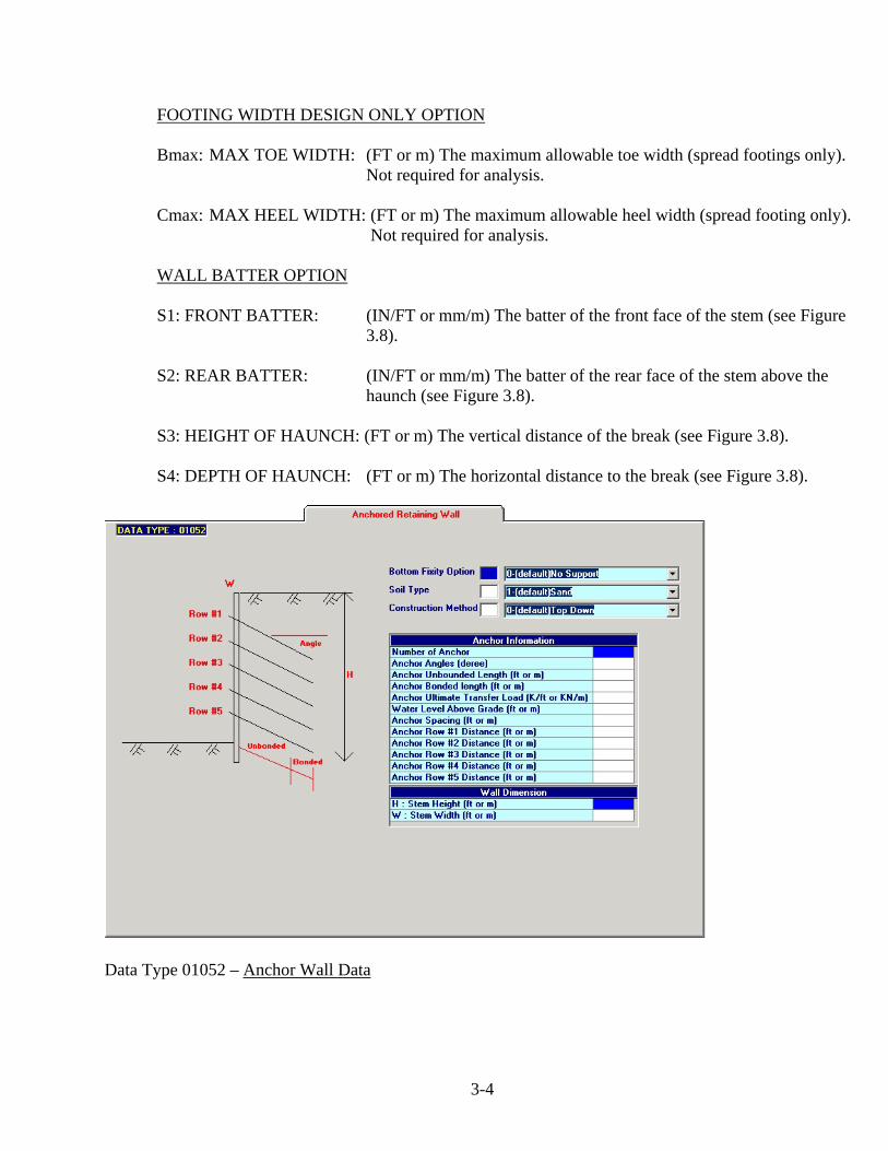
Data Type 01052 – Anchor Wall Data

3-5
BOTTOM FIXITY OPTION: Boundary Condition at the base of the wall. Use O in column 11 if no support is considered. Use 1 if only lateral support is considered. Use 2 if both lateral and moment support is considered.
SOIL TYPE: Three soil types for apparent earth pressure distribution are specified in AASHTO standard. Use 1 in column 12 for sand (or permanent walls in clay), 2 for soft to medium clay 3 for stiff to hard clay. If AASHTO LRFD is used, only Type 1 is used for more than one anchor used.
CONSTRUCTION METHOD: Use O in column 13 for more commonly used top down construction. Use 1 if bottom up construction is used in fill. ANCHOR INFORMATION
NUMBER OF ANCHOR: Enter number of anchor in column 14.
ANCHOR ANGLES (DEGREE): Anchor inclination with respect to the horizontal plane (columns 15 to 20).
ANCHOR UNBONDED LENGTH (Feet or Meters): As per AASHTO. 15Ν is the minimum (column 21 to 26).
ANCHOR BONDED LENGTH (Feet or Meters): Anchor pullout capacity is the bonded length times the anchor resistance (columns 27 to 32).
ANCHOR ULTIMATE TRANSFER LOAD (K/ft or KN/m): The resistance may be estimated by the values shown in AASHTO Standard or AASHTO LRFD Spec., or from the results of anchor pullout load tests (columns 33 to 38).
WATER LEVEL ABOVE GRADE (Feet or meters): Water level above grade for horizontal pressure due to water. No input if there is no water pressure (columns 39 to 44).
ANCHOR SPACING (Feet or meters): Spacing between anchors (columns 45 to 50).
ANCHOR ROW DISTANCE (Feet or meters): Distance from the top row of anchor to the top of the wall. The top of the wall is assumed free and the bottom is free or fixed by input. The anchoring location is considered fixed laterally (columns 51 to 80, for 5 entries).
WALL DIMENSIONS STEM HEIGHT: (Feet or meters) The height of the stem. STEM WIDTH: (Feet or meters) The width of the stem.

3-6
Data Type 01062 – Abutment Wall Data WALL DIMENSIONS
H: STEM HEIGHT: (FT or m) The height of the stem above the top of the footing (see Figure 3.8). A: STEM TOP WIDTH: (FT or m) The width of the stem at the top (see Figure 3.8). B: TOE WIDTH: (FT or m) The initial width of the toe to the front face of the stem (see Figure 3.8). Not required for design. C: HEEL WIDTH: (FT or m) The initial total width of the heel to the front face of the stem (see Figure 3.8). Not required for analysis. T: TOE THICKNESS: (FT or m) The initial thickness of the toe (see Figure 3.8). D: ABUTMENT SEAT WIDTH: (FT or m) E: ABUTMENT SEAT HEIGHT: (FT or m) Distance from top of the abutment wall to the seat.

3-7
FOOTING WIDTH DESIGN ONLY OPTION
Bmax: MAX TOE WIDTH: (FT or m) The maximum allowable toe width (spread footings only). Not required for analysis.
Cmax: MAX HEEL WIDTH: (FT or m) The maximum allowable heel width (spread footing only). Not required for analysis. WALL BATTER OPTION S1: FRONT BATTER: (IN/FT or mm/m) The batter of the front face of the stem (see Figure
3.8). S2: REAR BATTER: (IN/FT or mm/m) The batter of the rear face of the stem above the haunch (see Figure 3.8). 3.3 SOIL DATA
Data Type 02022 – Soil Data and Configuration SOIL DIMENSIONS D: DISTANCE TO BREAK: (FT or m) S: SLOPE RATIO:

3-8
H: FREE BOARD: (FT or m) The height of exposed stem above the fill behind the wall (see Figure 3.8). W: DRAIN WIDTH: (FT or m) The width of horizontal fill behind the wall (see Figure 3.8). FOUNDATION MATERIAL UNIT WEIGHT: (PCF or Kg/m3) Unit weight of the soil supporting the wall (spread footings only). INTERNAL FRICTION ANGLE: (DEG) The angle of internal friction of the soil which supports the wall (spread footing). This parameter is used to determine the coefficient of friction for sliding. (See Figure 3.9) (REF. 3.1) WALL FRICTION ANGLE: (DEG) For Coulomb method only. COHESION VALUE: (PSF or MPa) For Rankine method only. The cohesive strength of the
material. This parameter can be neglected if insufficient soil data is available. The cohesive strength of the soil is used for sliding stability only.
FILL SOIL PROPERTY OPTION UNIT WEIGHT: (PCF or Kg/m3) The unit weight of the fill material. INTERNAL FRICTION ANGLE: (DEG) The angle of internal friction of the soil, which supports the
wall (spread footing). This parameter is used to determine the coefficient of friction for sliding. (See Figure 3.9.) (REF. 3.1)
SOIL ACTION OPTION ACTIVE Kv VALUE: The vertical component of the active earth pressure coefficient (see
Figure 3.2A) ACTIVE Kh VALUE: The horizontal component of the active earth pressure coefficient (see
Figure 3.2B) Kv ACTING: (%) The percentage of the vertical component of the active earth
coefficient – to be considered. This may range from 100% to 0% (Default).

3-9
3.4 MATERIAL AND DESIGN DATA
Data Type 02012 — Material and Design Parameters
MATERIAL DATA MODULAR RATIO N: The modular ratio defined as Es/Ec.
CONCRETE STRENGTH (fc’): (KSI or MPa) The ultimate compressive strength of concrete at 28 days. REINFORCEMENT YEILD STRENGTH (Fy): (KSI or MPa): The yield stress of the reinforcing steel. DESIGN OPTIONS
FIXITY OF RESULT: This input can be used to limit the maximum eccentricity of the resultant due to the vertical and horizontal loads on the footing. It is defined as follows:
FIXITY OF RESULT footing ofWidth
2 x resultant) center to from (Distance=

3-10
If this input item is left blank, the program will default automatically on a value of 1/3 as a limit on the kern of the section.
ALLOWABLE SOIL PRESSURE (KSF or MPa): The maximum allowable soil pressure for foundation material.
SAFETY FACTORS
SLIDING: The minimum factor of safety against sliding (spread footings only).
OVERTURNING: The minimum factors of safety against overturning (spread footings only). REINFORCE SIZE NO: #3 to #18 is allowed.
Data Type 02052 —Optional Unit Price Data
Defines the unit cost of construction materials.
FOOTING CONCRETE: ($/CYD or $/m3) The unit cost of footing concrete.
STEM CONCRETE: ($/CYD or $/m3) The unit cost of stem concrete.
REINFORCEMENT STEEL: ($/LB or $/kg) The unit cost of reinforcement steel. PILE: ($/PILE) Cost of pile.

3-11
3.5 LOAD DATA
Data Type 02032 — Surcharge Data
NUMBER: The number of the surcharge loading given as an integer. LOAD PATTEN:
1) POINT LOAD (see Figure 3.4). 2) LINE LOAD (see Figure 3.5). 3) PATCH LOAD (see Figure 3.6). 4) UNIFORM LOAD (see Figure 3.7).
DESCRIPTION: A description of the surcharge loading given as an alphanumeric.
LOAD CONFIGURATION
LENGTH: (FT or m) The length of the surcharge load taken parallel to the stem. Required for LINE and PATCH LOADS; leave blank for POINT and UNIFORM LOADS. WIDTH: (FT or m) The width of the surcharge load taken normal to the stem.
Required For PATCH LOADS; leave blank for POINT and UNIFORM LINE LOADS.

3-12
INTENSITY: (KIPS, KLF, KSF or KN, KN/m, KN/m2) The value of the load defined as follows:
1) POINT LOAD — KIPS or KN 2) LINE LOAD — KIPS/(FT of LENGTH) or KN/(meter of LENGTH) 3) PATCH LOAD — KIPS/(SQ FT) or KN/(SQ m) 4) UNIFORM LOADS — KIPS/(SQ FT) or KN/(SQ m)
LOAD LOCATION
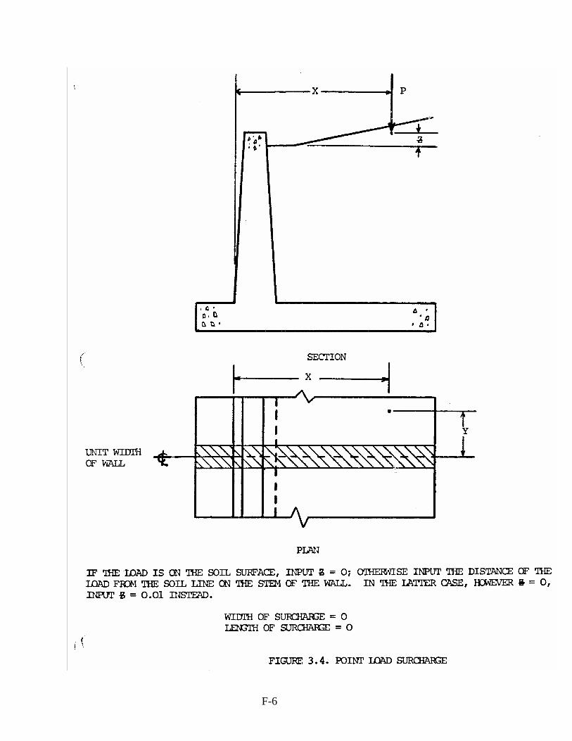
X: (FT or m) The horizontal distance of the surcharge loading from the reference line (see Figure 3.8); distance measured perpendicular to the stem of the wall.
Y: (FT or m) The horizontal distance of the surcharge loading from the center line of the
design unit width of wall; distance measured parallel to the stem of the wall.
Z: (FT or m) The vertical distance of the surcharge loading measured from the intersection of the backfill with the rear face of the stem of the wall (FT). The value may either be positive or negative input Z = 0 if the surcharge is on the soil surface (see Figures 3.4-3.7).
VERTICAL ACTING: (%) The percentage of the full vertical surcharge to act on the heel (for footing
and stability checks).
NOTE: The VERTICAL ACTING parameter is used to control overturning moment due to the vertical component of the surcharge. The engineer may wish to remove this component if the surcharge is not always present (since it forms a resisting moment which increases the factor of safety due to overturning and aids the resistance to sliding). However, a better means of determining the effect of the surcharge loads is to compare two runs . . . one with and one without the surcharge loadings.

3-13
Data Type 06012 — External Load Data LOAD NUMBER: Starting from 1. CODE ID: Load Code Identification for different types of load, e.g., ‘LL’ is the vehicular
live load. Types of Load (as defined in AASHTO LRFD Specifications)
DC: Dead load for components and attachments DD: Dead load for down drag DW: Dead load for wearing surfaces and utilities EH: Dead load due to horizontal earth pressure EV: Dead load due to vertical earth pressure ES: Dead load due to earth surcharge LL/IM/CE/BR/PL/LS:Live loads WA: Water load WS: Wind pressure on structures WL: Wind pressure on vehicles FR: Friction load TU/CR/SH/EL: Force effects due to superimposed deformation TG: Force effects due to temperature gradient SE: Force effects due to settlement

3-14
VERTICAL FORCE (KIPS or KN): Downward is positive. HORIZONTAL FORCE (KIPS or KN): Toeward is positive. BENDING MOMENT (KIPS or KN): Counter clockwise is positive. VERTICAL DISTANCE (FT or m): Load is applied at the location measured from the top of the wall
downward. HORIZONTAL DISTANCE (FT or m): Load is applied at the location measured from the Reference
Line heelward.

3-15
3.6 PILE DATA
Data Type 03012 — General Pile Properties PILE GENERAL DATA PILE TYPE, BEARING (0), FRICTION (1): Use integer 0 (or blank) if piles are end bearing; use integer 1
if piles are of the friction type (numbers should be put in the rightmost columns).
END CONDITION, HINGED (0), FIXED (1): Use integer 0 (or blank) if piles are hinged at the footing; use integer 1 if piles are fixed to the footing. REPRESENTATIVE LENGTH OF WALL (FT or m): The length of wall contributing load to the pile groups. MAXIMUM PILE BATTER RATIO: The maximum pile batter to which the pile design program can set any one row of piles. PILE AND SOIL MATERIAL PROPERTIES E OF PILE (KSI or MPa): The modulus of elasticity of the pile material. KS OF SUBGRADE (PCI or Kg/mm3): The subgrade modulus of the supporting soil.

3-16
NOTE: The subgrade modulus, Ks, is a measure of the ability of the soil to respond to force. It is, in effect, a spring constant with units pounds/inch or pounds per square inch of pile area per inch of soil deformation (extreme care must be used in interpreting this quantity when consulting the literature since the units are often not defined uniformly). It is recommended that the subgrade modulus NOT be used (i.e., input as zero) unless the design conditions warrant. Such conditions would be as follows:
1) The analysis of existing structures where the addition of piles would be extremely costly.
2) The analysis of statically unstable pile groups which can be made stable by the
definition of a subgrade modulus.
3) The analysis of structures from sites where sufficient soil data exists such that Ks can be properly defined.
It is also recommended that where the subgrade modulus Ks is used, that its value be chosen as the low limit of the range for the soil identified. It should be determined from plate bearing tests but, in a broad sense, it is given as follows: "For highly compressible silt, clay, or organic material, Ks = 0 pci to 170 pci; for low to medium silt or clay, Ks = 150 pci to 225 pci; for sand, fine or poorly graded, ks = 200 pci to 300 pci, and for clayey or well graded sand, fine gravel, ks = 250 pci to 450 pci." (REF. 3.3) The following is generally true with respect to the subgrade modulus:
1) The use of a subgrade modulus generally stiffens the foundation structure. (REF. 3.3);
2) Ignoring any soil resistance on the piling may yield incorrect solutions, since even a
minimal soil modulus stiffens the structure considerably. (REF. 3.2);
3) An analysis of a pile group ignoring the subgrade modulus yields results compatible with the Hrennikoff (REF. 3.2), the Elastic Center and other popular methods assuming compatible boundary conditions.
STEEL PILE TYPE: Section are preset to generate the pile section properties shown below. HP 10x42 HP 12x53 HP 14X73

3-17
PILE SECTION PROPERTIES PILE AREA (SQ IN or SQ mm): The area of the piles. PILE LENGTH (FT or m): The estimated length of piles. PILE INERTIA, X-X (IN4 or m4): The moment of inertia of an individual pile about an axis parallel to the stem. PILE INERTIA, Y-Y (IN4 or m4): The moment of inertia of an individual pile about its axis normal to the stem. PILE WIDTH, X (IN or mm): The width of an individual pile parallel to the stem. PILE WIDTH/HEIGHT, Y(IN or mm): The width of an individual pile normal to the stem. PILE PATTERN NUMBER (1-6): H dimension entered as Representative length of Wall in Pile General Data is the distance along X coordinate. Program will automatically generate piles and their associated properties on the next screen (Data Type 03022). User may enter pile data one by one on the next screen if the prescribed patterns do not match.
Data Type 03022 — Individual Pile Properties NO: An integer number assigned to each pile starting with 1 and progressing serially to the total number of piles.

3-18
NOTE: For pile design — piles should be numbered sequentially, starting with row under the toe, and with the pile with the most negative y coordinate (see Figure 3.10).
ROW NO: An integer number used only during pile design assigning the piles to specific rows. This
number should start with 1 under the toe, progressing serially towards the heel. COORDINATES:
X: (FT or m) The X coordinate of each pile with respect to the front face of the stem at the top of the footing. (See Figure 3.10.)
Y: (FT or m) The Y coordinate of each pile with respect to the centerline of the group. (See
Figure 3.10.) PILE FACTOR: The fractional portion of pile which acts in the representative wall segment (e.g., 0.5 represents 50% of a pile). BATTER:
ANGLE: (DEG) The horizontal angle defining the direction of the batter; 0o is towards the heel, 180o is towards the toe, leave blank for plumb piles. (See Figure 3.10.)
INPUT RATIO: The batter defined as follows:
Batter Input Ratio batter ofcomponent Vertical
batter ofcomponent Horizontal=
Leave blank for plumb piles. For example, a 4:1 batter would be input at .25 value.
MAXIMUM BATTER RATIO: The maximum pile batter ratio allowed for each row. All piles within any row should be battered the same.
NOTE: This value should be the same as maximum pile batter ratio from data type 3012.
BATTER OPTION, FIXED: An integer 1 placed here will leave the pile batter unaltered by the pile design program, leave blank if pile batter is to be designed or if plain pile analysis is to be done.

3-19
REFERENCES 3.1 Anderson, W.C., "Foundations to Resist Tilting Moments Imposed on Upright Cantilevers
Supporting Highway Signs," Sign Supports, Foundation Design, Bulletin 247, Highway Research Board, Washington, DC, 1960, pp. 1-13.
3.2 Hrennikoff, A., "Analysis of Pile Foundations with Batter Piles," ASCE Transactions, Paper No.
2401, February 1946, pp. 351-381. 3.3 Saul, William E., "Static and Dynamic Analysis of Pile Foundations," Journal of the Structural
Division, ASCE, Vol. 94, May 1968, pp. 1077-1100. 3.4 Bowles, J. E., Foundation Analysis and Design, McGraw-Hill, Inc., New York, NY, 1968. 3.5 Bowles, J. E., Analytical and Computer Methods in Foundation Engineering, McGraw-Hill, Inc.,
New York, NY, 1974. 3.6 Spangler, M. G., and Handy, R. L., Soil Engineering, 3rd ed., Intext Educational Publishers, New
York, NY, 1974. 3.7 Terzaghi, K. and Peck, R. B., Soil Mechanics in Engineering Practice, 2nd ed., John Wiley and Sons,
Inc., New York, NY, 1968. 3.8 ACI 318-99, Building Code Requirements for Structural Concrete (ACI 318-99) and Commentary
(ACI 318 R-99), American Concrete Institute, Farmington Hills, MI 48333. 3.9 AASHTO, Standard Specifications for Highway Bridges, 16th Edition, with 1997-2000 Interims,
American Association of State Highway and Transportation Officials. 3.10 AASHTO, AASHTO LRFD Bridge Design Specifications, 1998 with 1999, 2000 Interims,
American Association of State Highway and Transportation Officials.

4-1
4.0 OUTPUT All output is given in the form of tables that are identified by number. These can be output selectively by the use of OUTPUT LEVEL (as defined in TABLE 3.1.1 — DEFINITION OF OUTPUT LEVELS). 4.1 VERIFICATION OF INPUT Output Table 1.1 — INPUT VERIFICATION
Input verification yields the output of all input given on Input Sheets 1 of 3 through 3 of 3 as close to the original format as possible.
4.2 STEM DESIGN Output Table 2.1 — STEM DESIGN DATA
NO: The number of the section along the stem starting from the first section from the top.
DISTANCE FROM TOP OF STEM (FT or m): The location of the section from the top of the wall.
STEM, MOMENT (FT-K or m-KN): The moment in the stem due to the fill and surcharge loadings.
STEM, SHEAR (K or KN): The shear in the stem due to the fill and surcharge loadings.
STEM, THICKNESS (IN or mm): The thickness of the stem at the section location.
STRESSES, Fc (KSI or MPa): The compressive stress in the concrete in the outer fibers of the stem section.
STRESSES, Fs (KSI or MPa): The tensile stress in the tensile steel.
STRESSES, Fs' (KSI or MPa): The compressive stress in the compressive steel.
STEEL AREAS, As (SQ IN or SQ mm): The required area of tensile steel.
STEEL AREAS, As' (SQ IN or SQ mm): The required area of compressive steel constrained by the inputted maximum compressive reinforcement steel area allowed in the stem.
DEVELOPMENT LENGTHS-TENSION (FT or m): The minimum development lengths of rebar required for bonding.

4-2
DEVELOPMENT LENGTHS-COMPRESSION (FT or m): The minimum development lengths of rebar required for bonding.
DESIGN NOTES
See TABLE 4.2.1 — DESIGN NOTES FOR STEM for a description of all notes. 4.3 STABILITY Output Table 3.1 — STABILITY ANALYSIS DESIGN NOTES
See TABLE 4.3.1 — DESIGN NOTES FOR STABILITY ANALYSIS for a description of all notes.
Output Table 3.2 — PILE GROUP ANALYSIS
PILE NO: The identification number assigned to each pile.
SHEAR FORCE, X-X (K or KN): The horizontal shear force exerted on the pile due to the horizontal forces acting on the wall.
SHEAR FORCE, Y-Y (K or KN): The horizontal shear force exerted on the pile in a direction parallel to the wall.
AXIAL FORCE (K or KN): The axial force in the pile.
MOMENT, X-X (K-FT or KN-m): The moment in each pile about axis parallel to the wall.
MOMENT, Y-Y (K-FT or KN-m): The moment in each pile about axis normal to the wall.
NOTE: If the piles are hinged at top or if the subgrade modulus, ks, is zero, all moments at the top of each pile will be zero.
DESIGN NOTES
See TABLE 4.3.2 — DESIGN NOTES FOR PILE FOUNDATION for a description of all notes.
4.4 FOUNDATION DESIGN Output Table 4.1 — FOOTING DESIGN DATA

4-3
LOCATION WITHIN FOOTING: The location within the footing for which steel information is given.
STEEL AREAS (SQ IN/FT or SQ mm/m): The area of steel required.
DEVELOPMENT LENGTHS (IN or mm): The minimum development lengths of rebar required for bond.
DESIGN NOTES
See TABLE 4.4.1 — DESIGN NOTES FOR SPREAD FOOTING for a description of all notes.
Output Table 4.2 — FOOTING DESIGN DATA
LOCATION WITHIN FOOTING: The location within the footing for which steel information is given.
STEEL AREAS (SQ IN/FT or SQ mm/m): The area of steel required.
DEVELOPMENT LENGTHS (IN or mm): The minimum development lengths of rebar required for bond.
DESIGN NOTES
See TABLE 4.4.2 — DESIGN NOTES FOR PILE CAP for a description of all notes. 4.5 QUANTITIES Output Table 5.1 — RETAINING WALL QUANTITIES DESIGN NOTES
See TABLE 4.5.1 - DESIGN NOTES FOR QUANTITIES for a description of all notes.

5-1
5.0 DIAGNOSTICS 5.1 GENERAL The diagnostics that are output to the program fall into three categories: FATAL ERRORS NON-FATAL ERRORS DESIGN AND ANALYSIS CHECKS 5.2 FATAL ERRORS
Those diagnostics which are designated as FATAL ERRORS involve errors which are serious to the degree that they will terminate the run. There are the F-type errors which are defined in Table 5.2.1 — FINAL ERROR DIAGNOSTICS. In many cases, they are easily corrected. Here every attempt is made to let the user know where the error occurred and to give an indication where possible, of all errors before the run is terminated.
5.3 NON-FATAL ERRORS
Those diagnostics which are designed as NON-FATAL ERRORS involve errors which will not terminate the run, which may effect some of the results. These are the C-type errors which are defined in Table 5.3.1 — NON-FATAL ERROR DIAGNOSTICS and again, in many cases, are easily corrected.
5.4 DESIGN AND ANALYSIS CHECKS
Finally, those diagnostics which are designated as DESIGN AND ANALYSIS CHECKS involve errors which have been discovered intermediate in the run, probably by virtue of the irregularities in the design. These are the D-type errors which are defined in Table 5.4.1 — DESIGN AND ANALYSIS CHECKS. These errors are often not easy to correct because alterations in design process or input data might be necessary. Also, the errors might not cause the termination of the run necessarily.

6-1
6.0 EXAMPLE PROBLEMS

6-2

6-3

6-4

6-5

6-6

6-7

6-8

6-9

6-10

7-1
7.0 METHODOLOGY 7.1 GENERAL This system designs or analyzes a cantilever retaining wall either on a spread footing, on piles, or an anchored wall. It has the capability of performing the following operations automatically: 1) Computing active earth coefficients for level, infinitely sloping, or broken slope backfire
conditions. 2) Considering the effects of additional surcharge loading for point, line, patch, and uniform
loads applied one by one or in combination behind the wall. 3) For the "analysis" option, it will compute the required steel areas for given concrete sections
and analyze the wall against sliding, overturning, excessive soil pressure, and resultant location.
4) For the "design" option, it will add a key, increase the real wall batter, and optimize the
footing size for spread footing if required and permitted by the user through the input data. It will compute the required steel areas, taking into account all increments for concrete section and analyze wall against sliding, overturning, excessive soil pressure and resultant location.
7.2 EARTH PRESSURES A. General Horizontal and vertical soil coefficients may be entered either directly into the program as input or may be computed by the program using the soils data. If horizontal coefficient ( HK ) and vertical coefficient ( VK ) are entered directly, the analysis proceeds, using these values, which remain unchanged regardless of the slope configuration or size of the footing. If the values of VK , and HK , are computed by the program, either the Coulomb or Rankine method for active earth pressure coefficients is used. These values for VK and HK , are adjusted for computations of wall stability and pressure because the plane on which the earth pressures act extends vertically from the end of the heel to the ground surface. Any incrementation of the heel therefore changes the values for VK and HK for a broken slope backfill condition. Values for VK and HK , for the design of the stem are based only on the input stem configuration and are not changed if the rear face batter dimensions are incremented. A reduction factor is provided such that the percentage VK used for design may vary from zero to the full amount of VK . It should be noted that all horizontal and vertical forces are consistent throughout the design and analysis process. A method for computing the estimated active earth pressure against the retaining wall and estimated vertical stresses on the heel is presented here. There are numbers of special field conditions which may be encountered in practice which require modification to this recommended

7-2
procedure. These are as follows: 1) A U-Wall or similar type of construction cannot tilt or slide through a distance
sufficient to develop the full shearing resistance of the backfill. Consequently, the earth pressure acting on the wall is greater than the active earth pressure. At rest, earth pressure should be used in these cases, which use requires special consideration.
2) Highway traffic, vibratory loading, or repetitive loadings within the influence zone
of the wall require special consideration. 3) The force of freezing behind the wall is a special condition and should be
considered, if appropriate. 4) If a water table exists behind the wall, it should be included in the total lateral
pressure. B. Lateral Earth Pressure
1) Backfill surface—infinite slope: For the backfill surface having infinite slope, the lateral earth pressure is computed by Coulomb Theory:
( )
( ) ( ) ( )
2
2
2
coscos)sin()sin(
1coscos
cos
⎥⎥⎦
⎤
⎢⎢⎣
⎡
−+−+
++
−=
ii
Kff
fa
βδβφδφ
δββ
βφ
or Rankine Theory:
f
fa
ii
iiiK
φ
φ
φββ
φβββ
22
22
22
22
coscoscos
coscoscoscos
coscoscos
coscoscoscos
−+
−−
−+
−−=
Where aK = coefficient of active earth pressure
fφ = Angle of internal friction for backfill soil (DEGREE)
i = Slope angle of backfill, which should not be greater than ( )2.3−φ
degree in order to assure stability of the infinite slope (DEGREE).
β = Slope of the stem face (DEGREE)
δ = Friction angle between wall and soil (DEGREE).
Then compute aa KHP ××= 22
1 γ ;
where aP = Resultant active earth pressure assumed to act parallel to the backfill
slope at a point 3/oH and 3/sH for overturning and stem

7-3
design, respectively (KIPS);
γ = Unit weight of backfill (KCF)
oH = Height of a vertical plane through the base of the footing heel to an
intersection with the ground slope (See Figure 7.1.). This parameter
is used for determining overturning moment and the design of the
footing;
sH = Height of a vertical plane passing through the rear face of the wall at
the base of the stem to a point of intersection with the ground slope
(see Figure 7.2).
Here, iPP aH cos= and iPP aV sin=
where HP = Horizontal component of active earth pressure aP (KIPS);
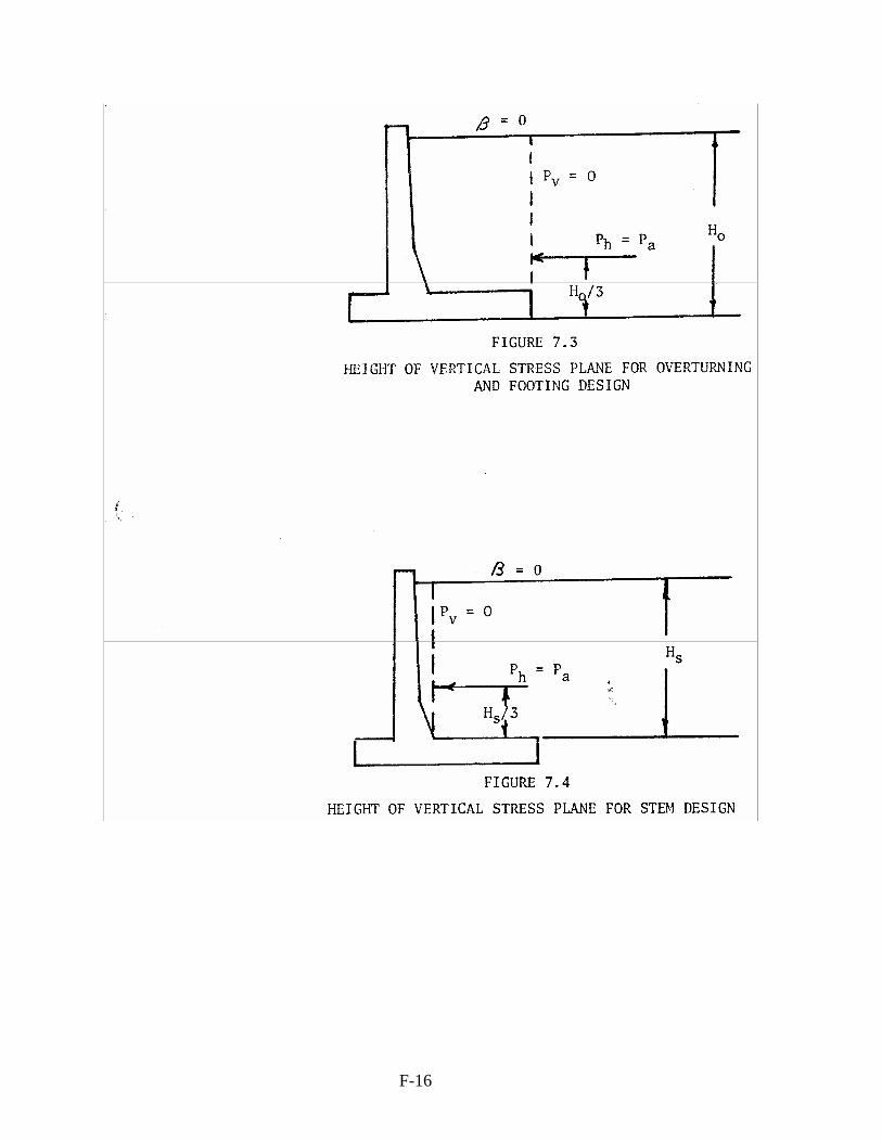
and VP = Vertical component of active earth pressure aP (KIPS); 2) Back fill surface—horizontal: This case is similar to case 1 above, expect that i=0. Since the resultant pressure is assumed
to be acting parallel to the ground surface, the HP computed is equal to aP
and 0=VP (see Figures 7.3 and 7.4.)
3) Backfill surface—broken: For backfill surface having a break in the slope, the lateral earth surface differs depending upon the position of the breaking point, as follows:
a) For 6.0/1 ≤HH :
Backfill surface—Infinite slope solution applies;
b) For 6.0/1 >HH :
The aK value for this case is intermediate between that for an infinite slope and a
horizontal backfill. Therefore, aK may be computed by a straight line interpolation
between the aK values obtained for case 1 and case 2.
( ) ( ) ( ) ( )HHcaseKcaseKcaseKK aa
aa1
6.0212 −
+=
where H = Height of vertical stress plane ( FT ). Use oH for overturning and footing

7-4
design and SH for stem design;
1H = The vertical distance of the slope break (FT). Use1OH for overturning and
footing design and 1SH for stem design;
1OH = Vertical distance between slope break and a point defined by the intersection
of a vertical line projected from the heel and to the ground slope (see Figure
7.5);
1SH = Vertical distance between slope break and a point defined by the intersection
of a vertical line projected from the heel/stem interface to the ground slope (see
Figure 7.6.)
The force aP , due to the active earth pressure, is given by:
aP = aKH 22
1 γ
Since K is known, substitute aK in the equation below to compute the backfill equivalent
slope angle
0coscoscos2coscoscos4 222223 =Φ−Φ−Φ− faeaeea KiKiiK .
From Rankine's assumptions, ei is also the angle at which aP intersects the vertical plane
(see Figures 7.5 and 7.6).
Here, eaH iPP cos= ;
eaV iPP sin= .
C. Vertical Earth Pressure
The vertical component of the earth pressure is computed using value of VK . A reduction
factor is provided such that the percentage VK used for design may vary from zero to the
full amount of VK . The lower the percentage (it may be specified as zero) the more
conservative the design will be with respect to the sliding and overturning. Vertical earth
pressure on the toe may be omitted by specifying a zero depth of fill on the toe. Usually it is
desirable to omit the vertical pressure on the toe because the overburden may be excavated in
the future.

7-5
D. Earth Pressure for Anchored Wall
The earth pressures on anchored walls constructed in fill situations from the bottom up are
affected by the method and sequence of construction. Therefore, the method and sequence of
construction must be considered when selecting appropriate lateral earth pressures for
anchored walls in fill situations.
(1) For walls with a simple anchor level—A triangular distribution defined by γaK per
unit length of wall height plus surcharge loads.
(2) For walls with multiple anchor levels—For walls constructed in fill form from the
bottom up, a rectangular pressure distribution derived by increasing the total force from the
triangular pressure distribution described in (1) by 30% and applying the force as a uniform
pressure distribution, HK saγ ′ . For walls constructed from the top down, the uniform
pressure is HKP saa γ ′= 65.0 .
(Note: Above pressures are defined by AASHTO LRFD Specifications. For WSD/LFD
top-down methods, AASHTO standard has guidelines for 3 types of soil.)
7.3 SURCHARGE LOADING
A. General
This program computes both the horizontal and vertical effects [of] loadings on the stem and the footing for up to 9 surcharges, combining these effects with the earth load forces. A reduction factor is provided such that the percentage of the vertical surcharge force effects may vary from 0 to 100%. To analyze the effects of the surcharges, the backfill soil surface is idealized as a grid system. The cells are square with lengths and widths of 1/10 of the wall height. If a distributed load does not cover a whole cell, then the cell is assumed to be covered by a uniform load of the following magnitude.
actualreduced QAREACELLTOTALCOVEREDCELLOFAREAQ ×=
The cell loads then are assumed to be concentrated at the centers of the cells. For point loads, however, the actual X and Y dimensions are used for analysis, as well as the X dimension for

7-6
line loads.
B. Lateral Surcharge Load Effects For computing the horizontal pressures against a vertical stress plane parallel to the stem, the stress plane height is taken as:
a) sH , the difference in elevation between the top of the heel footing and the ground
surface over the heel side of the stem base. The height is taken as sH for computing
the load effects on the stem and for finding the effects of loads over the heel on stability
(see Figures 7.2, 7.4, and 7.6.)
or
b) oH , the difference in elevation between the bottom of the footing and the ground
surface over the heel end. oH is used as the stress plane height for computing the
effects of loads outside of the heel on stability (see Figures 7.1, 7.3, and 7.5). The lateral surcharge effects are calculated taking the load in each loaded cell of the grid as a point load using the following equations which were developed by Spangler (Ref. 7.1);
1) To find horizontal influence from a point load laying in a plane and normal to the
vertical stress plane, the equation is
( )322
22
2
77.1nmnM
HV
h+
×=σ
( )32222 /77.1 XXZVX += ; for m<0.4, use m=0.4;
where
hσ = horizontal influence at any depth Z (see Figure 7.7) in the vertical stress plane
due to point load (KSF);
H = height of vertical stress plane (FT);
X = the horizontal distance of the surcharge loadings from the stress plane; distance
measured perpendicular to the stem of the wall (FT) (see Figure 3.4);
Y = the horizontal distance of the surcharge loadings from the design unit wall;
distance measured parallel to the stem of the wall (FT) (see Figure 3.4);

7-7
Z = the vertical distance of the surcharge loading measured from the intersection of
the backfill with the rear face of the stem of the wall (FT). The value may be
either positive or negative (see Figure 3.4);
m, n = X/H and Y/H, respectively;
v = point load (KIPS).
2) To find horizontal influence from a point laying to the side of the perpendicular plane:
First, compute hσ from the equation given above and use
hσ ′ = )1.1(cos2 ασ ×h ;
nσ ′ = horizontal influence (see Figure 7.8) at any point defined by angle α (KSF);
α = angle between the plane through the load and perpendicular to the vertical
stress plane and the point for which hσ ′ is derived (RAD). Only surcharges within 1.5 × the stress plane height in the X direction and 2.85 × the corresponding X coordinate for the Y direction are considered as effective in producing horizontal forces on the design strip of the stress plane (see Figure 7.9). The stress plane is divided into 20 increments at which the forces and moments are evaluated.
C. STEM DESIGN
For stem design, the stress plane is located above the heel side of the stem base with the
height of sH (see Figure 7.9). At each cross section down the stem at which the concrete
design is required, the forces and moments along the stress plane sH are evaluated. These
forces then are load factored for the concrete design, if required.
For stem design, all surcharge loads located on a sloping or broken ground surface are
assumed to act on a horizontal plane passing through the points of intersection created by the
vertical plane through the rear face at the base of the stem and the sloping or broken ground
surface (see Figure 7.13).
D. STABILITY ANALYSIS For overturning and sliding stability analyses, the stress plane is located above the base of the footing at the heel end. In addition to the effects of surcharges outside of the stress lane, the forces from surcharges over the heel also are found on this plane. The greater of the moments and forces caused by either the surcharges over the heel, or past the heel, are taken for sliding

7-8
and overturning.
NOTE: For overturning, if the surcharge moment on the sH plane is
greater than that on the oH plane, then the surcharge moment on the
sH plane will be used for the stability analysis. For stability and soil pressure analyses and footing design, the surcharge elevations are idealized as the following: a) Surcharge loads located on a sloping or broken ground surface beyond the vertical
plane through the heel are assumed to act on a horizontal plane passing through the point of intersection created by the vertical plane passing through the heel and the sloping or broken ground surface (see Figure 7.12).
b) Surcharge loads located on a sloping or broken ground surface between the vertical
plane above the rear stem base and the plane over the midpoint of the heel projector are assumed to act on a horizontal plane passing through the point of intersection created by the vertical plane through the rear face at the base of stem and the sloping or broken ground surface. Between the midpoint of the heel projection and the end of the heel, the elevation of the surcharge is idealized as the same elevation as for case (a) (see Figure 7.12.)
E. VERTICAL SURCHARGE LOAD FORCES
The vertical forces and moments on the heel from surcharge loadings are found from the equation developed by Boussinesq (Ref. 7.1), which is given below.
2512
32
2 ⎟⎠⎞
⎜⎝⎛ +
=
ZRZ
Qνσ
where, νσ = Vertical influence of a point load on the footing base (KSF);
Q = Point load (KIPS);
R = Horizontal distance between a point load and the point where the νσ
is derived (FT);
Z = Vertical distance from a point load to top of the footing (FT).
The heel is divided into incremental lengths 1/10 × wall height. The vertical pressures are
computed at the centers of these increments and are used for the stability analyses and the
heel footing design.

7-9
Only surcharges within 1.5 oH from the end of the heel in the X direction are considered.
For the Y direction, surcharges within 1.5 sH from the center line of the design width of
wall are considered if they are over the heel. If outside the heel, surcharges within 1.5 oH
from the design width of wall are considered.
For surcharges outside of a distance = stem height from the stem of the wall in the X
direction, the Boussinesq equation is evaluated using the coordinates of each loaded grid cell
or point load. These figures are summed for each increment of heel length (see Figure 7.10.)
For surcharges within one stem height from the stem, the straight Boussinesq equation is not
valid since the soil cannot be assumed to be continuous past the stem of the wall. Instead, the
Boussinesq equation is integrated from the end of the heel to infinity past the toe. This
represents the sum of the force that would be predicted by the Boussinesq equation to be
acting on the soil to the left of the heel end. This force then is assumed to be distributed
uniformly over the heel V. (See Figure 7.11.) The integrated Boussinesq equation is given
below:
2
2
2
22 113
132
23
ZR
ZRZ
Q
R
+
⎟⎟⎟⎟⎟
⎠
⎞
⎜⎜⎜⎜⎜
⎝
⎛
⎟⎟⎠
⎞⎜⎜⎝
⎛+
+=νσ
7.4 KEY DEPTH
A. General
For spread footing design, if the factor of safety for sliding is inadequate, a key will be designed if indicated to be permitted in the input data. The sliding of a retaining wall without a key on its base is resisted by the friction between the concrete base and the soil. The resistance to sliding may be increased by the use of the key that projects into the soil below the base. The heel also may be widened to increase the amount of backfill overburden, and thereby the amount of normal force, on the heel. For the same volume of concrete, the key ordinarily is considered to be somewhat more

7-10
effective than an increase in base width. However, the excavation for the key is likely to disturb the subsoil during construction, and in some instances conceivably may do more harm than good unless the key is embedded in rock, stiff cohesive soil, or undisturbed soil. The initial key depth, in the design mode, will vary according to the following table:
Footing Width Key Depth Up to 6' 1' Over 6' up to 9' 11/2' Over 9' up to 12' 2' Over 12' up to 15' 21/2' Over 15' 3'
These depths are required to insure soil-on-soil friction below the entire footing in front of the key.
B. Sliding Resistance Two possible sliding failure modes are considered for retaining walls with keys: Mode 1. Friction failure In this case the wall fails by sliding along a failure plane extending from the bottom of the key toward the end of the toe. The friction coefficient along this plane is taken as tanθ . The normal force is due to the soil pressure distribution over this plane. The full cohesion value also is considered as effective against sliding on this plane.
Outside of this soil-on-soil slip plane, the coefficients of friction and cohesion are taken as
θtan32 and c2
1 , respectively, for calculating the concrete-on-soil sliding resistance. Mode 2. Passive Pressure Failure The alternate failure situation accounts for the passive earth pressure on the front face of the key. Friction and cohesion are assumed to act over the whole footing base as was discussed above for the concrete-on-soil sliding region. The passive pressure results from the vertical soil pressure at the front edge of the key and from the soil weight below the footing bottom. The failure mode with the lesser sliding resistance is assumed to control for design. The key depth is set initially at 12" and is adjusted upward in 1/4-ft increments until the desired safety factor against sliding is obtained. If the desired sliding resistance is not

7-11
obtained by the time the key depth has reached the limit which was input, then the depth no longer will be increased. The design process will continue using this depth with an appropriate message printed out.
C. Concrete Design For the case of friction failure, the design load is caused by the friction and cohesion over both the soil-on-soil failure plane and the bottom of the key. The forces from the soil-on-soil cohesive and friction forces on the key are assumed to have a triangular distribution starting from zero at the top to a maximum pressure at the bottom of the key. The passive earth pressure is assumed to be distributed over the face of the key for concrete design. The soil friction, and cohesion on the key bottom, also are included in the design shear and moment for the passive pressure failure condition. The key thickness is incremented in inches and is initially set at 12'. It is adjusted first to the thickness required for shear and then incremented upward, if necessary, for moment.
D. Design Notes 1) The key design is based on the assumption that the foundation soil is undisturbed below
the footing. If this soil is disturbed during excavation for the key of footing, then the shear and passive pressure capacities of the soil may be lessened greatly.
2) If it is allowed, moving the location of the key under the footing may increase, or,
conversely, decrease the sliding resistance. Moving the key toward the toe probably will increase the passive pressure resistance. Moving the key toward the heel will increase the friction resistance.
Important: If the front face of the key is within 6 in. of the toe, the passive soil pressure caused by the vertical soil pressure will be disregarded.
7.5 STABILITY
A. General
For walls supported by a spread footing, checks are made for overturning stability, sliding stability, soil pressure, and resultant locations. To satisfy these criteria, the toe and heel are incremented within the limitations defined in the input data.
B. Overturning If the factor of safety against overturning is inadequate, the toe and heel are incremented

7-12
alternately in three-inch units satisfied. Incrementing either toe or heel will not be made beyond the limitations set forth in the input data.
C. Sliding If the factor of safety against sliding is inadequate, incrementation of the heel is made to a maximum of the input limitations. If this occurs prior to meeting the sliding factor of safety, the factor of safety will be printed. Diagnostic messages will appear stating that the footing is inadequate and the actual factor of safety will be printed. If the input indicates that a key is allowed, execution will continue, designing a key, up to the maximum input limitation. The final key design and safety factor will be printed with a diagnostic message if the key is inadequate to satisfy sliding.
D. Soil Failure If the maximum allowable toe pressure is exceeded, the toe dimension will be incremented in three-inch units until the pressure is within the allowable pressure. Incrementing of the toe will be made to a maximum of the input limitations at which time the heel will be incremented in three-inch units if pressure still is too high. The heel will be incremented to a maximum of the input limitations until the pressure is within the allowable value. A diagnostic message will be printed if the pressure cannot be satisfied within these limits and execution will continue.
E. Resultant Check The toe and heel both are incremented in three-inch units until the location of the resultant of all vertical and horizontal loads meets the input requirement of the limit on the maximum eccentricity of the resultant. If the limit in input data is 0 (or left blank), the program automatically will set the value to 0.33.
7.6 SECTION DESIGN
A. General The design of concrete sections is accomplished by using the working stress design or ultimate strength design methods depending upon the input defined by the user. The ultimate strength design requires the conversion of the design working loads to design ultimate loads through the use of load factors, which are defined automatically by the program.
B. Concrete Theory The design may be based on working stress design method in which stress in reinforcing steel and concrete must be kept within certain allowable limits so that an approximately linear

7-13
relationship exists between stress and strain in both concrete and steel. While, if design is based on ultimate strength design, both concrete and reinforcing steel can be stressed fully. In working stress design method, triangular stress block is assumed and the section is designed to resist moment and shear. While, for ultimate strength design, rectangular stress block is assumed and section is designed for ultimate moment and shear (REFS. 7.2 and 7.4). In order to ensure yielding-type failure, the steel ratio should not exceed
×= 75.0maxρ balanced steel ratio. The balanced steel ratio is the amount of steel necessary for the failure of the section both by crushing of the concrete and yielding of the steel occurring at the same load (REF. 7.6).
C. Stem Design The system computes areas both for tensile and compressive reinforcement at various locations in the stem. The maximum area of compression reinforcement is checked at the base of the stem and also at the haunch, if any, in the rear face of the stem. If the area of the compression reinforcement at the haunch is excessive, the rear face batter is incremented in 1/8-inch per foot units until the area is within the allowable value. Also, if the area of compression reinforcement at the base of the stem is too great, the break point is held and the horizontal dimension of the haunch "D" is incremented in 1.0-inch units. If there is no haunch, the area of the compression steel is checked only at the base of the stem. If it is excessive, the rear face batter is incremented in 1/8-inch per foot units until the steel area is within the allowable value. Once the compression reinforcement is checked as outlined above, intermediate sections are designed. If the areas of compression reinforcement at these sections are excessive, a diagnostic message and execution continues. The system neglects the axial load due to the weight of the stem in the stem design and does not consider vertical loads applied on the top of the wall. The earth pressure plane for the design analysis of the stem sections is defined as starting from the point of intersection of the footing and the rear face of the stem and extending vertically to the earth surface. If the rear face batter of the stem is adjusted by the systems, the heel width dimension is reduced by the amount of increase in the stem thickness prior to starting the footing design. This dimension will not be reduced to less than zero. For the analysis option, only the input configuration is considered (i.e., the batter dimensions are not incremented), and areas of required tension and compression steel is computed.
D. Footing Design
The system proceeds with initial toe and heel dimensions as indicated on the input data, and checks sliding stability, overturning stability, soil pressure, and resultant location. To satisfy all these criteria, the heel and toe dimensions are incremented as described earlier until all criteria are satisfied through the limitations set in input data.

7-14
Once the width of the footing satisfies the checks outlined above, tensile and compressive reinforcement are computed. If the thickness of the footing is too small, resulting in excessive compression steel and shear stresses, the thickness will be increased in one-inch units until the areas of compressive reinforcement and the shear stresses fall within the allowable values. The thickness also will be decreased if the initial thickness is excessive. For the analysis option, the reinforcement requirements and stresses are evaluated for concrete and reinforcement for the input wall configuration. No incrementation of footing dimensions is performed.
7.7 PILE GROUPS
A. General For pile supported footings, the pile group is analyzed using a stiffness method solution. A subgrade modulus may be specified so that pile configurations which otherwise would be unstable may be analyzed. Before using a subgrade modulus, the designer's supervisor should be consulted. The pile foundation consists of a group of piles placed into the soil, topped with a reinforced concrete cap. Loads to the cap and the weight of the cap are borne to the soil by the pile group. Determination of deflections of individual pile is required by the designer. The individual pile loads are determined and it is left to the designer to check the computed loads against the maximum allowable capacity for an individual pile. This system does not adjust the pile group in the event of an overload condition. The individual pile moments and shears are computed in directions parallel and perpendicular to the wall.
B. Theory The pile group as per input data is analyzed using the method of direct stiffness of three dimensional pile foundations for static loading or dynamic response. The pile foundation consists of a group of piling placed into the soil and, on its top, a reinforced concrete cap is provided. Loads to the cap and weight of the cap are borne to the soil by the pile group (REF. 7.5). The pile may be friction pile or end bearing pile, having end condition either fixed or hinged. The behavior of individual piles in their local coordinates is related to the systems of pile foundation through the global coordinates to obtain the stiffness of the whole foundation. For analysis of pile system, model representative of the soil pile interaction is required. Most models simply disregard lateral capacity and assume all pile forces to be axial. Thus, batter piles are considered to be resisting horizontal components.

7-15
C. Design Method
For walls to be founded on the pile foundations, the pile pattern is assumed. This may consist of plumb and batter piles to resist vertical and horizontal forces. The piles are designed as a group by computing the center of gravity and moment of inertia of all piles and computing the overturning moment and eccentricity of load at the plane of the tops of the piles. By drawing a force diagram, the load on each pile can be computed and compared with the allowable loads. Once the pile loads are determined, tensile and compressive reinforcement are designed. If the thickness of the footing is too small, resulting in excessive compression and shear stresses, it is increased in one-inch increments until the shear stress and areas of compressive reinforcement fall within the allowable values. For analysis option, the steel requirements and stresses for concrete and steel are evaluated for the input wall configuration. No incrementation of footing is performed.

7-16
REFERENCES
7.1 Bowles, J. E., Foundation Analysis and Design, McGraw-Hill, Inc., New York, NY, 1968. 7.2 Bowles, J. E., Analytical and Computer Methods in Foundation Engineering, McGraw-Hill, Inc., New York, NY, 1974. 7.3 Spangler, M. G. and Handy, R. L., Soil Engineering, 3rd ed., Intext Press Inc., New York, NY. 7.4 Ferguson, P. M., Reinforced Concrete Fundamentals, 3rd ed., John Wiley and Sons, Inc., New York, NY, 1973. 7.5 Saul, W. E., "Static and Dynamic Analysis of Pile Foundations," Journal of the Structural Division, ASCE, Vol. 5, No. STS, Proc. Paper 5936, May 1968, pp. 1077-1100. 7.6 Winter, G. and Nilson, A. H., Design of Concrete Structures, 8th ed., McGraw-Hill, Inc., New York, NY, 1973. 7.7 Barker, R.M., Duncan, J.M., Rojiani, K.B., Ooi, P.S.K., Tan, C.K., Kim, S.G., "NCHRP Report 343: Manual for the Design of Bridge Foundations," Transportation Research Board, Washington, D.C., 1991.

T-1
TABLES

T-2

T-3

T-4

T-5

T-6

T-7

T-8

T-9

T-10

T-11

T-12

T-13

T-14

T-15

T-16

T-17

F-1
FIGURES

F-2

F-3

F-4

F-5
F-6

F-7

F-8

F-9

F-10

F-11

F-12

F-13

F-14

F-15
F-16

F-17

F-18

F-19

F-20

F-21

F-22