wind energy new dimensions in metrology
TRANSCRIPT

Wind Energy –
New Dimensions in MetrologyThomas Wiedenhöfer, Frank Härtig

page 2 of 18
sailing vessels in the
ancient Egypt
ChronologyApplication of wind energy about 1500 BC
windmills in China
photo: Elvira Kronlob source: Carl von Canstein
page 3 of 18
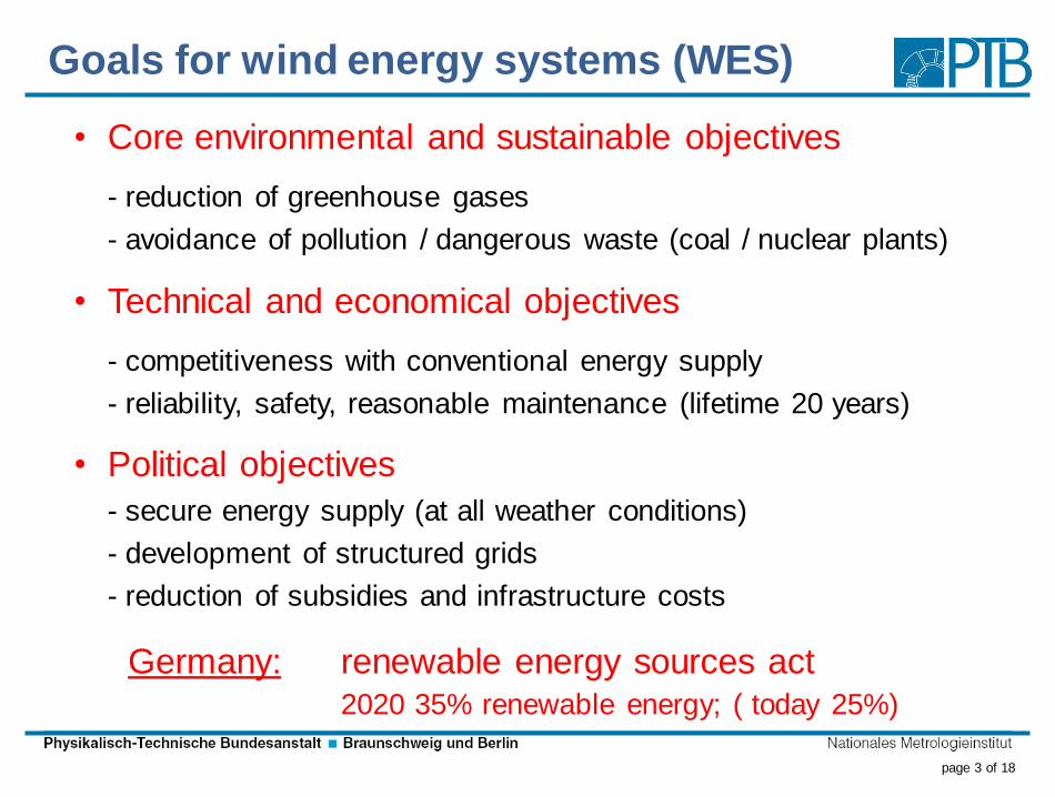
Goals for wind energy systems (WES)
• Core environmental and sustainable objectives
- reduction of greenhouse gases
- avoidance of pollution / dangerous waste (coal / nuclear plants)
• Technical and economical objectives
- competitiveness with conventional energy supply
- reliability, safety, reasonable maintenance (lifetime 20 years)
• Political objectives
- secure energy supply (at all weather conditions)
- development of structured grids
- reduction of subsidies and infrastructure costs
Germany: renewable energy sources act2020 35% renewable energy; ( today 25%)
page 4 of 18
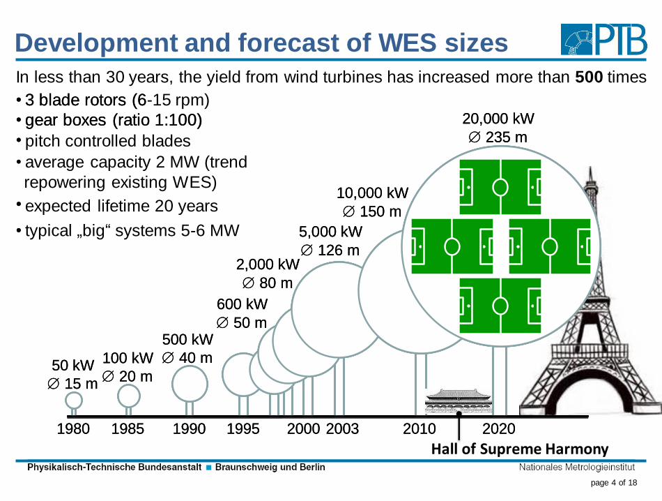
Development and forecast of WES sizes
1980 1985 1990 1995 2000 2003 2010 2020
50 kW
15 m
100 kW
20 m
500 kW
40 m
600 kW
50 m
2,000 kW
80 m
5,000 kW
126 m
10,000 kW
150 m
20,000 kW
235 m
1980 1985 1990 1995 2000 2003 2010 2020
50 kW
15 m
100 kW
20 m
500 kW
40 m
600 kW
50 m
2,000 kW
80 m
5,000 kW
126 m
10,000 kW
150 m
20,000 kW
235 m
• 3 blade rotors (6
• gear boxes (ratio 1:100)
• pitch controlled blades
• average capacity 2 MW (trend
repowering existing WES)
• expected lifetime 20 years
• typical „big“ systems 5-6 MW
In less than 30 years, the yield from wind turbines has increased more than 500 times
• 3 blade rotors (6-15 rpm)
• gear boxes (ratio 1:100)
•
•
•
Hall of Supreme Harmony
page 5 of 18
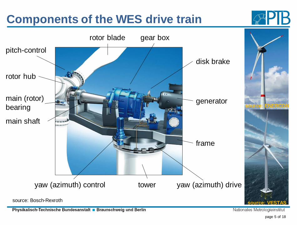
Components of the WES drive train
source: Bosch-Rexroth
pitch-control
rotor hub
main (rotor)
bearing
main shaft
rotor blade
yaw (azimuth) control
gear box
disk brake
generator
frame
yaw (azimuth) drivetower
source: ENERCON
source: VESTAS

page 6 of 18
Failure frequencies and impacts
source: Fraunhofer IWES, Kassel
annual failure frequency downtime per failure in days
drive train
support & housing
generator
gearbox
rotor Blades
mechanical brake
rotor hub
yaw system
hydraulic system
sensors
electronic control
electrical system
1 0.75 0.5 0.25 0 2 4 6 8
annual failure frequency downtime per failure in days
drive train
support & housing
generator
gearbox
rotor Blades
mechanical brake
rotor hub
yaw system
hydraulic system
sensors
electronic control
electrical system
1 0.75 0.5 0.25 0 2 4 6 8

page 7 of 18
Cost distribution caused by WES failures ‘09
source: Sensen, Gothaer Allgemeine Versicherung AG
wind rotors
21.1 %
others
9.1 %generators
15.1 %converters
7 %
trans-
formers
7.2 %
other
electrical failures
13.8 %
gear boxes
26.6 %
page 8 of 18
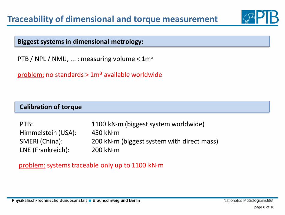
Traceability of dimensional and torque measurement
Calibration of torque
PTB: 1100 kN·m (biggest system worldwide)Himmelstein (USA): 450 kN·mSMERI (China): 200 kN·m (biggest system with direct mass)LNE (Frankreich): 200 kN·m
Biggest systems in dimensional metrology:
PTB / NPL / NMIJ, ... : measuring volume < 1m3
problem: no standards > 1m3 available worldwide
problem: systems traceable only up to 1100 kN·m
page 9 of 18
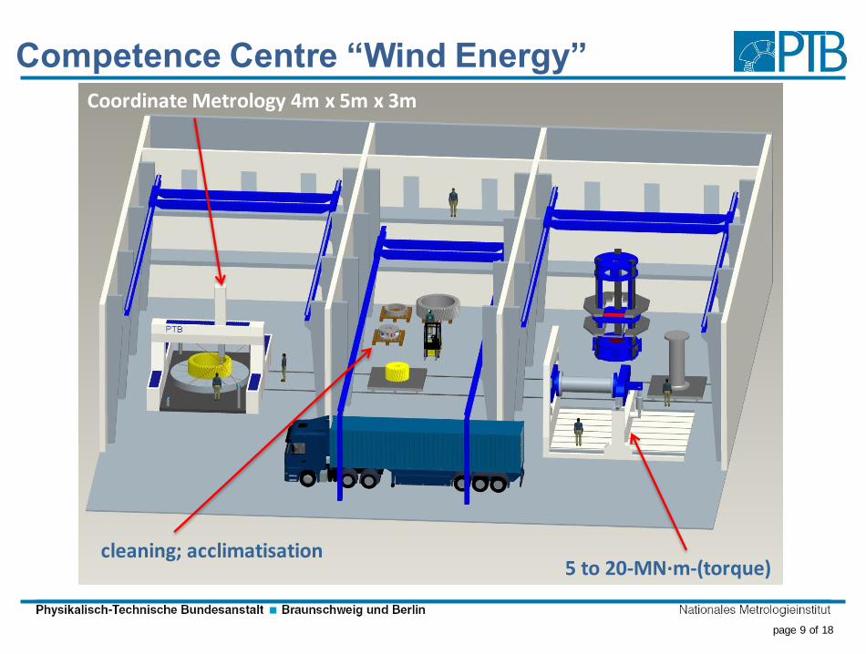
Competence Centre “Wind Energy”
5 to 20-MN·m-(torque)
Coordinate Metrology 4m x 5m x 3m
cleaning; acclimatisation

page 10 of 18
Calibration of large involute gear artefact
measurements in industry
mover: CMM
environment: measuring room
workpiece: calibrated involute gear artefact
(reference, validation)
Parameter Value
Number of teeth z 38
Normal module mn 20 mm
Pressure angle n 20°
Face width b 400 mm
Helix angle 0°/spur; 10°/R; 20°/L
Outside diameter da 1000 mm
Weight 450 kg (700 kg)
Reference bands
diameter (form deviation)
200 mm (1 µm)
Calibration for gear measurement today
page 11 of 18
3D-Abbe principle – task specific correction
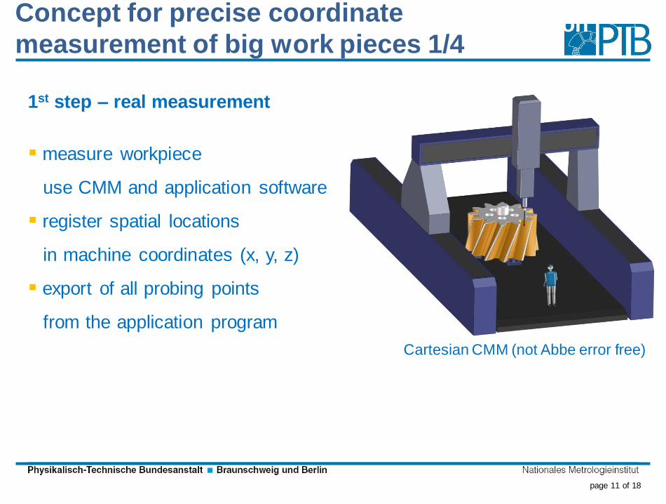
1st step – real measurement
measure workpiece
use CMM and application software
register spatial locations
in machine coordinates (x, y, z)
export of all probing points
from the application program
Cartesian CMM (not Abbe error free)
Concept for precise coordinate
measurement of big work pieces 1/4

page 12 of 18
3D-Abbe principle – task specific correction
2nd step – 3D-Abbe measurement
remove workpiece
exchange stylus by triple reflector
approximately at same centres
Cat-Eye
working range 120°
n=2-ball
working range 160°
align at least 4 tracking interferometers
move to all measurement points
measured in step 1
synchronised read out of all tracking interferometer
3D Abbe error free
measurement for
measurements
on Cartesian CMMs
Concept for precise coordinate
measurement of big work pieces 2/4

page 13 of 18
3rd step – evaluate the local error vector and
correct mover points
Mover position during measuring
M3D3 coordinates during error mapping
Error vector
Mover position indicated during error mapping
Correctedmover position
Concept for precise coordinate
measurement of big work pieces 3/4

page 14 of 18
Calibraition of large involute gear artefactConcept for precise coordinate
measurement of big work pieces 4/4

page 15 of 18
Calibration of torque 5 MNm to 20 MNmpart under test

page 16 of 18
conventional LIDAR new – LIDAR calibration system
to be calibrated Measurement height: 10m – 200m
measuring mast free
MU: 0,1 m/s; spatial resolution: 10-9 m3
Third part of CC-Wind: Wind-Lidar

page 17 of 18
Clues for further development and needs
source: Fraunhofer IEWSsource: Fraunhofer IEWS
http://strom-report.de/
offshore
employment
systems
capacity
Onshore Germany
page 18 of 18
Physikalisch-Technische Bundesanstalt
Braunschweig and Berlin
Bundesallee 100
38116 Braunschweig
Thomas Wiedenhöfer (Wiedenhoefer)
Telefon: +49 (0)531 592-1189
E-Mail: [email protected]
Thank you for your kind attention