wind-to-hydrogen project: electrolyzer capital …wind-to-hydrogen project: technical report...
TRANSCRIPT

Wind-To-Hydrogen Project: Electrolyzer Capital Cost Study
Genevieve Saur
Technical Report NREL/TP-550-44103 December 2008

Technical Report Wind-To-Hydrogen Project: NREL/TP-550-44103
Electrolyzer Capital Cost Study December 2008
Genevieve Saur Prepared under Task No. H271.3730
National Renewable Energy Laboratory1617 Cole Boulevard, Golden, Colorado 80401-3393 303-275-3000 • www.nrel.gov
NREL is a national laboratory of the U.S. Department of Energy Office of Energy Efficiency and Renewable Energy Operated by the Alliance for Sustainable Energy, LLC
Contract No. DE-AC36-08-GO28308

NOTICE
This report was prepared as an account of work sponsored by an agency of the United States government. Neither the United States government nor any agency thereof, nor any of their employees, makes any warranty, express or implied, or assumes any legal liability or responsibility for the accuracy, completeness, or usefulness of any information, apparatus, product, or process disclosed, or represents that its use would not infringe privately owned rights. Reference herein to any specific commercial product, process, or service by trade name, trademark, manufacturer, or otherwise does not necessarily constitute or imply its endorsement, recommendation, or favoring by the United States government or any agency thereof. The views and opinions of authors expressed herein do not necessarily state or reflect those of the United States government or any agency thereof.
Available electronically at http://www.osti.gov/bridge
Available for a processing fee to U.S. Department of Energy and its contractors, in paper, from:
U.S. Department of Energy Office of Scientific and Technical Information P.O. Box 62 Oak Ridge, TN 37831-0062 phone: 865.576.8401 fax: 865.576.5728 email: mailto:[email protected]
Available for sale to the public, in paper, from: U.S. Department of Commerce National Technical Information Service 5285 Port Royal Road Springfield, VA 22161 phone: 800.553.6847 fax: 703.605.6900 email: [email protected] online ordering: http://www.ntis.gov/ordering.htm
Printed on paper containing at least 50% wastepaper, including 20% postconsumer waste

Acknowledgements
I would like to personally thank Kevin Harrison, National Renewable Energy Laboratory in Golden, Colorado, U.S.A., and Andrew Martin, Royal Institute of Technology in Stockholm, Sweden, for their help in realizing this opportunity. I also want to thank Todd Ramsden, George Sverdrup, and the U.S. DOE’s Hydrogen Program without whose help and tools this would not have been possible.
I would also like to acknowledge and extend my gratitude to Sudipta Chakraborty, Greg Martin, Bruce Green, everyone at the National Wind Technology Center, and my dear friends and family who helped me get through.
iii

Table of Contents
Acknowledgements .......................................................................................................... iii
Table of Contents ............................................................................................................. iv
List of Tables ......................................................................................................................v List of Figures .....................................................................................................................v
1 Introduction ..................................................................................................................1 2 Background ..................................................................................................................2 3 Methodology .................................................................................................................7 4 Data ...............................................................................................................................9
4.1 Cost Breakdown—PEM.........................................................................................10 4.2 Cost Breakdown—Alkaline ...................................................................................11 4.3 Improvement Assessment ......................................................................................11
5 Analysis .......................................................................................................................13 5.1 H2A Parameters .....................................................................................................14 5.2 Capital Cost Sensitivity..........................................................................................15 5.2.1 Stack Cost Reduction .....................................................................................15 5.2.2 Power Electronics Cost Reduction.................................................................19 5.3 Efficiency Improvement Sensitivity ......................................................................22 5.4 Capital Cost Versus Efficiency ..............................................................................26
6 Conclusion ..................................................................................................................29
References .........................................................................................................................31
Appendix 1. Company Survey List ................................................................................34 Appendix 2. Company Feedback Request .....................................................................35 Appendix 3. H2A Assumed Parameters.........................................................................41
iv

List of Tables
Table 1. PEM Electrolyzer Company Response—Development Level Versus Primary Application ........................................................................................... 10
Table 2. Capital Costs Used in H2A Analysis .................................................................. 15 Table 3. Capital Cost Range with Stack Cost Reductions ................................................ 16 Table 4. Data Table for Reduction of Stack Cost for 10 kg/Day ...................................... 17 Table 5. Data Table for Reduction of Stack Cost for 100 kg/Day .................................... 18 Table 6. Data Table for Reduction of Stack Cost for 1,000 kg/Day ................................. 18 Table 7. Capital Cost Range with Power Electronics Cost Reductions ............................ 19 Table 8. Data Table for Reduction of Power Electronics Cost for 10 kg/Day ................. 20 Table 9. Data Table for Reduction of Power Electronics Cost for 100 kg/day ................ 21 Table 10. Data Table for Reduction of Power Electronics Cost for 1,000 kg/Day .......... 22 Table 11. PEM Efficiency Scenarios for H2A.................................................................. 23 Table 12. Data Table for Cost Effects of Increasing Efficiency for 10 kg/Day ............... 24 Table 13. Data Table for Cost Effects of Increasing Efficiency for 100 kg/Day ............. 25 Table 14. Data Table for Cost Effects of Increasing Efficiency for 1,000 kg/Day .......... 26 Table 15. Data for Price Reductions with 0% to 30% Improvement, Capital Cost Versus
Efficiency ........................................................................................................... 28
List of Figures
Figure 1. Cost breakdown PEM (all PEM) ....................................................................... 10 Figure 2. Cost breakdown alkaline (all alkaline) .............................................................. 11 Figure 3. Company response—average collected response .............................................. 12 Figure 4. Weighted potential............................................................................................. 13 Figure 5. H2A analysis reduction of stack cost for 10 kg/day .......................................... 17 Figure 6. H2A analysis reduction of stack cost for 100 kg/day ........................................ 17 Figure 7. H2A analysis reduction of stack cost for 1,000 kg/day ..................................... 18 Figure 8. H2A analysis reduction of power electronics cost for 10 kg/day ...................... 20 Figure 9. H2A analysis reduction of power electronics cost for 100 kg/day .................... 21 Figure 10. H2A analysis reduction of power electronics cost for 1,000 kg/day ............... 21 Figure 11. H2A analysis cost effects of increasing efficiency for 10 kg/day ................... 24 Figure 12. H2A analysis cost effects of increasing efficiency for 100 kg/day ................. 25 Figure 13. H2A analysis cost effects of increasing efficiency for 1,000 kg/day .............. 26 Figure 14. Capital cost versus efficiency, price reductions for 0% to 30% improvement 27
v

1 Introduction
Could hydrogen be the fuel of the future that powers vehicles and balances the electric grid for renewable energies? That is the question many parties want answered. Creating that reality requires producing hydrogen on a scale much greater than current production. Even before the high cost of oil increased gasoline prices, there was a great deal of interest in using alternative fuels. Hydrogen can be used in a variety of applications, including as transportation fuel and for generating electricity by using fuel cells or internal-combustion engine generators. Hydrogen has great potential, but for it to be an energy panacea it requires sustainable, economic large-scale production.
This study is being performed as part of the National Renewable Energy Laboratory’s (NREL’s) renewable electrolysis task which is funded by the U.S. Department of Energy (DOE). The aim of the project is to identify areas for improving the production of hydrogen from renewable energy sources at a much larger scale. These areas include both technical development and cost analysis of systems that convert renewable energy to hydrogen via water electrolysis. Increased efficiency and reduced cost will bring about greater market penetration for hydrogen production and application. There are different issues for isolated versus grid-connected systems, however, and these issues must be considered. The manner in which hydrogen production is integrated in the larger energy system will determine its cost feasibility and energy efficiency.
Several renewable integration studies [1, 2, 3, 4] have focused on the larger chain from renewable source to hydrogen production, examining such elements as capital costs and operations and maintenance (O&M). In many cases, these studies are more concerned with identifying the cost or sizing implications for grid-connected versus isolated systems, and determining the hydrogen cost under those circumstances. Finding the integration plan that best meets the needs of the community obviously is an important element.
The focus of this study is to capture a single segment of the chain for analysis so that a better picture of each stage of the process can be drawn. To meet DOE targets for hydrogen cost a more detailed analysis examining performance and economic factors that might be reduced, as well as where further research could be directed, is required. Here electrolyzers are identified as a key element in the renewable hydrogen chain and a significant factor in the overall cost of hydrogen.
Electrolysis is one method by which hydrogen can be produced cleanly from renewable sources. Today’s other primary methods require using fossil fuels, such as natural gas and coal. They also have the disadvantage of producing a variety of pollutant and greenhouse gases (CO2, CO, NOX) which, in light of climate change research, are problematic and require subsequent filtering and use of carbon sequestration technologies to be clean. The splitting of water using electrolysis especially when coupled with renewable energy sources has fewer air pollution impacts than do fossil-fuel sources of hydrogen. Electrolysis requires electricity to power the process, however, and the source of this electricity determines the cleanliness of the process and the hydrogen fuel.
1

2
The cost of hydrogen is a big factor for its adoption as an energy carrier. Its price will need to be competitive with that of fossil fuels, which have a great advantage in the current economic market due to their penetration and the existing environmental legislation. In conjunction with growing penetration of renewable energy sources, hydrogen could provide a clean fuel that also might aid in grid integration of the variable nature of wind and solar resources, but only if the price is competitive.
The purpose of this study is to provide an economic component cost analysis of electrolyzer units that are in commercial production or in development. The research aims to help support the growing case for electrolysis, confirm the potential for electrolysis as a hydrogen production method as well as identify key areas that may be improved in the future. Analysis of the current state-of-the-art technology can help provide a basis for where future improvements and funding might be best applied.
Background
Hydrogen is the lightest known element and is extremely abundant. In terms of energy content, it is the ninth most abundant element in the earth’s crust, and water is composed of 11.2% of hydrogen [1]. It is mainly found in composite compounds rather than in its molecular form which is gaseous at room temperature and pressure (25o C and 1 atm). Hydrogen is an energy carrier rather than a primary energy source, due to the need to extract it from the compounds in which it is bound. It holds properties that span between electricity, another energy carrier, and traditional fossil fuels. However, because it can be compressed and stored in large quantities and dispatched as needed, it is unlike electricity which must be used as it is generated and struggles with large-scale storage.
As an energy carrier hydrogen has some unique obstacles for its adoption. In terms of energy content, 1 kg of hydrogen is equal to approximately 1 gallon of gasoline, however as a gas its volumetric energy content is about one quarter that of the same volume of gasoline [2]. This means that high-density storage options are a necessity for some applications such as transportation, for example.
Current uses of hydrogen include production of ammonia for fertilizer, methanol production, petroleum refineries, hydrogenation, metal production, electronics manufacture, float gas production, and cooling of thermal generators [7, 8, 9, 10, 11]. Of these, however, ammonia, methanol, and petroleum refining are the largest applications. Global hydrogen production is about 500 billion Nm3/yr, of which the United States accounts for about 90 billion Nm3/yr (~8.1 billion kg/yr) and this has been growing at about 10% per year [3]. Globally, about 96% of hydrogen production comes from fossil fuels, and of this 48% is from natural gas reformation; in the United States, about 95% of hydrogen is produced from natural gas [7, 8, 9].
In comparison, the United States consumed approximately 143 billion gallons of gasoline in 2007 [4]. On an energy equivalent basis (1 gal gasoline ≈ 1 kg hydrogen), this gasoline usage would be equal to approximately 143 billion kg of hydrogen. Since hydrogen fuel cell vehicles are more efficient than the gasoline internal combustion engine vehicles they would replace, the United States would need less than this amount of hydrogen to fully
2

replace transportation gasoline. Even so, full replacement of gasoline in the transportation sector with hydrogen would require a several-fold increase from current hydrogen production levels. Though if fuel cell vehicles realize their greater efficiency potential this target could decrease. However, this does not include other fuels such as jet fuel, diesel, or heating oil. It clearly is a significant transition for hydrogen to replace existing transportation fuel.
There exist several motivations for transitioning to hydrogen fuel. One is the possibility of greater domestic energy production, thereby decreasing dependence on foreign oil imports. Another is the growing concern regarding climate change and the effect of man-made carbon dioxide on the atmosphere. As a fuel, hydrogen has the potential to be consumed relatively cleanly, either by combustion or by thermochemical reaction in fuel cells, and the main by-product of both is water. Hydrogen also can be used in the production of electricity or as a fuel for transportation and heating. Its production can be relatively clean (with some caveats). For these reasons it is sometimes called a clean fuel.
Hydrogen only is as clean as its source. The fossil-fuel-based production methods of today generally are not clean because there is no abatement of the carbon released during the process (i.e., using carbon capture and sequestration). In centralized production using abatement techniques, fossil-fuel-based processes could be used along with a clean end use that would decrease the amount of the carbon dioxide emitted to the atmosphere. However, these ultimately would be dependent on the reserves and source of the feedstock, mainly natural gas in the United States. There are several potential renewable methods for producing hydrogen: electrolysis, biomass gasification/pyrolysis, fermentation, thermolysis via solar driven thermochemistry, photolysis via photoelectrochemistry, and photolysis via photobiology [8, 13]. Of these, electrolysis is commercialized in several niche markets: space, military, laboratory, and some industry. Biomass gasification and fermentation are in development, but for the most part are not at commercialized stages. The other processes still require a good deal of research before their potential will be realized. In the near term, more attention is being paid to electrolysis because of its current market penetrations and possibilities, and for that reason is the focus of this paper.
Electrolysis is a process by which electricity is used to split water into its component parts: oxygen and hydrogen. Under ideal circumstances it requires 39.4 kWh of electricity and 8.9 liters (l) of water at normal conditions (25o C and 1 atm) to make 1 kg of hydrogen. This represents the higher heating value (HHV) of hydrogen, which includes the total amount energy (thermal and electrical) to disassociate water at normal conditions. Some reports and tools use the lower heating value of hydrogen (LHV) for efficiency comparisons and this is equivalent to an electrical input of 33.3 kWh/kg of hydrogen. System efficiency is calculated by dividing the heating value (LHV or HHV) by the real energy input in units of kWh/kg. This leads to a maximum efficiency of 82% based upon LHV while system efficiency based upon HHV has a theoretical maximum of 100%. The maximum efficiency can never be reached because the process is never perfectly ideal due to thermodynamics as well as material limitations. The current electrolyzer efficiencies generally are in the range of 52% to 82% (HHV) [5].
3

There are two main commercialized types of low temperature electrolyzers, an older more established alkaline chemistry and a newer polymer electrolyte membrane (PEM). A third type, solid oxide, is still only in research stages, and a survey of companies found no systems being sold commercially. Alkaline and PEM are low-temperature electrolysis technologies, because the reactions occur at temperatures less than the boiling point of water, usually less than 80o C [2, 6]. Alkaline electrolyzers have been shown to be most efficient around 50o C, with stack efficiency leveling off and increasing very minimally between 50o C and 80o C [7].
There are both similarities and differences between the two electrolyzer designs. Alkaline systems use an electrolyte solution of potassium hydroxide (KOH) with either a bipolar or unipolar stack design. The anode and cathode are where the production of oxygen and hydrogen occurs, respectively. PEM stacks use a solid membrane electrolyte whereby ions pass through the membrane for production of oxygen on one side and hydrogen on the other.
Both systems require the input of deionized (DI) water. PEM water-purity requirements are higher than alkaline constraints. Direct current (DC) is required to provide the activation energy for the electrolysis reaction. This DC power to the stack is the majority of the electrolyzer’s load; additional ancillary power is also used for the rest of the system loads. Power electronics to convert the alternating current (AC) of the grid is required, and this is usually a significant cost element—often second to the cost of the stack itself. Alkaline systems generally use current densities of between 200 mA/cm2 and 600 mA/cm2, and PEM systems generally run at greater than 1,500 mA/cm2 [8, 9].
There are tradeoffs between the current density, stack efficiency, and the capital costs, whereby greater current density increases rate of production but reduces efficiency [10]. The optimum densities are part of the development process and are based upon standard operating conditions. The PEM electrolyzers often require greater production rates brought about by greater current density to offset a greater capital cost. This, in turn, leads to lower stack efficiencies. One advantage of PEM electrolyzers, however, is the ability to run with a differential pressure across the hydrogen and oxygen side. This means that high-pressure equipment is needed only for the hydrogen gas if the oxygen is simply vented at or near atmospheric pressure. Additionally, less control-system overhead is required for keeping the pressures equalized between the two sides.
There are commercial uses for pure oxygen, and it is unclear whether or not the additional capital cost to the electrolyzer warrants the benefits of large-scale oxygen capture [11]. In 2003 oxygen represented about a one billion dollar market in the US as an industrial gas [12] so there could be benefit in selling oxygen in these established markets. Whether new markets could emerge, such as for fuel cells, is unclear. Regardless, higher system pressure output of hydrogen increases the specific energy consumption of the stack but reduces need for further compression downstream; which can be a significant energy and cost component in the full system [13, 14]. Most transportation technologies require compressed hydrogen that is in the range of 5,000 psi to 10,000 psi, whereas output from the stack is typically between 0 psi and 500 psi [5]. There are electrolyzer systems in development, however, that could produce ultra-high
4

pressure without requiring external compression, such as Avalence’s Hydrofiller which reaches 6,500 psig [15]. A study has also shown a PEM technology that could electrochemically produce differential pressure of up to 2,400 psi or more [2, 16]. The output pressure is a factor for comparing different electrolyzer systems.
In December 2006, the U.S. DOE published the “Hydrogen Posture Plan”[17], which outlined goals of President Bush’s Hydrogen Fuel Initiative. One goal was a delivered hydrogen target of $2.00 to $3.00 per gal of gasoline equivalent (gge) [18]. There are multiple storage mechanisms for hydrogen, such as compressed gas, cooled liquid, or in metal hydrides. Conversion to mass basis allows easy equivalence of the energy content even though per volume the mechanisms would be vastly different which is important to particular delivery and end use applications. However by mass basis this target also gives $2.00 to $3.00 per kg hydrogen, with 1 kg of hydrogen having approximately the same energy equivalent as 1 gallon of gasoline assuming the same end-use conversion efficiency.
Water electrolysis could play a major role in renewable hydrogen production, especially in the period before other renewable processes have developed and matured. There are obstacles to reducing the cost of hydrogen produced from electrolysis, however, NREL developed the H2A Production model to transparently and consistently analyze the cost of hydrogen production from different pathways [19]. Using the H2A Production model, the cost of hydrogen from electrolysis can be broken down into the price of electricity, the capital cost, and the system efficiency of electrolyzers. The electricity price is assumed to aggregate the costs of the sources whether from the electricity grid or as a standalone source. In the H2A analysis of distributed production, termed “forecourt,” the cost of electricity was the biggest contributor to the hydrogen cost, followed by capital cost. Only for the smallest systems (approximately 100 kg/day and less) did this sensitivity reverse such that capital cost overtook electricity cost as being the primary factor [5]. This assessment of the major cost factors for hydrogen produced from electrolysis is confirmed in reports from Europe [20, 21, 22, 23, 24], where the cost of electricity in some countries makes electrolysis untenable economically. Capital cost of both electrolyzers and hydrogen infrastructure could be a big hindrance as well. Even marginal capital cost reduction could make a big difference for the cost of hydrogen [20]. Therefore reducing capital cost in electrolyzer systems could have a distinct effect on their feasibility and potential for achieving the DOE target of between $2.00/kg and $3.00/kg.
The high capital-cost investment required for electrolyzers typically makes running them at full or near-full load and high-capacity factors a requirement for better overall economic feasibility [25, 26, 27]. This is especially true because even in idling mode electrolyzers can draw 21% to 29% of their rated power [31, 32]. If integrated with renewable sources, then generally this necessitates incorporation with the grid for variable sources or the ability to purchase off-peak electricity to boost production [20, 28]. In using grid electricity, the hydrogen produced by electrolysis is only as clean as the composite electricity it uses. Electrolytic hydrogen production has several grid benefits especially when combined with renewable integration. Studies suggest that with high penetration of wind hydrogen production it will help improve utilization of these variable
5
renewable energy (RE) sources [13] and improve the plant load factors for the rest of the grid mix [29, 30]. This can help reduce cost and emissions of carbon intensive sources.
Cost-competitive electrolysis has several potential benefits, including:
• easing the introduction of greater renewable electricity sources;
• functioning as a fuel for transportation or other sectors; and
• reducing dependence on fossil fuel.
These are competing objectives that would have to be balanced as hydrogen production is increased. Renewable energy studies conducted in the United States suggest that there is enough wind and solar potential to produce hydrogen for the transportation sector, although there are many infrastructure hurdles to overcome before this can be a reality [5].
Most studies have focused on sizing issues related to the electricity source, electrolyzers, and storage. The requirements are site and resource dependent, with consideration given to such components as grid support, off-grid, and hydrogen requirements. These elements greatly affect the overall cost of hydrogen; a well-considered system makes best use of the resources and components involved [31, 32]. A well-defined system has appropriately sized elements that minimize downtime or wasted energy and maximize hydrogen production for the stated requirement. This requires attaining high capacity or load factors for each subsystem, including wind turbines, photovoltaics, and electrolyzers.
The obstacle becomes capital investment: Where and how can it be reduced. Several case studies developed by H2A use electrolysis for hydrogen production. In these studies, the capital cost of the electrolyzer units was aggregated into a cost per unit or per kilowatt. In the wind electrolysis case study, for instance, the uninstalled electrolyzer units amounted to more than 36% (44% installed) of the total capital investment, and capital-related costs equaled 76% of the total lifetime investment [33]. Analysis of the best ways to reduce capital cost therefore will reveal the overall economic value of the system and the cost of hydrogen produced. The model can be further refined by breaking down the costs. Additionally, improvements can be made by closely tying electrolyzers to renewable sources by either eliminating redundant power conversions or by collecting similar subsystems into one part and increasing efficiency of the entire chain.
A study of the more detailed aspects of commercial or near commercial electrolyzer units could provide a better picture of the current state of the technology and its projected course, and what subsystems can be improved by closely linked integration. The component analysis can provide a clearer picture of where the majority of the cost lies and which subsystems have the best potential for savings. This could come from design improvements, mass-production benefits, or efficiency. The analysis results will provide insight to industry and other stakeholders on where the opportunities lie to improve capital costs and efficiencies.
6

3 Methodology
This study was performed in collaboration with companies that have commercial or near-commercial electrolyzer systems. The economic information that was gathered had good applicability to this analysis because it came from sources with the parallel goal of business profitability. Ultimately, the aim of the research is to identify economically feasible systems. Two electrolysis chemistries are analyzed here, PEM and alkaline; these are the only two low-temperature electrolyzers currently on the market. A list of companies that markets these units is supplied in Appendix 1
A questionnaire (Appendix 2) was developed and was distributed to each of the companies. Subsystems are lumped together to allow a greater degree of granularity without divulging individual company design. This could be done because there are common elements to electrolyzers that have only a few differences in individual company design or chemistry type.
Generally, electrolyzer systems contain the following elements.
• Electrolyzer stack
• Power electronics
• Control systems
• Gas conditioning (phase separation, drying)
• Water/electrolyte circulation Most larger systems also can require cooling. Alkaline systems typically require additional electrolyte management as well as pressure management systems for keeping the oxygen and hydrogen sides equalized. Therefore, rather than investigating individual designs, the subsystems were broken down roughly to enable categorical conclusions. PEM and alkaline systems are presented separately in the component-cost breakdown and all company responses (alkaline and PEM) are aggregated for the speculation portion and to protect answers from respondents.
It is difficult to elicit actual costs from companies, due to sensitive proprietary information they might include. Therefore, rather than using actual costs, only percentages of the total cost were requested. These data indicate where the relative costs are in the designs without remarking on individual company practices. Also requested was company opinion regarding the technology and its strengths and weakness. Each individual company’s information was carefully obscured from the final analysis, to respect the expectations of protecting proprietary products.
There are certain assumptions made regarding the information that was gathered. These assumptions impact both how the data are interpreted and the types of conclusions that can be made from the aggregated data.
• Commercialized systems are relatively cost optimized for their specific applications. Prototype and units in R&D might not be optimized similarly.
7

• Electrolysis technology currently is not optimized for mass production. Units are produced on a made-to-order basis. There might be savings from mass production of some subsystems, but other subsystems could increase in cost due to an increased demand for precious materials in a finite material environment.
• The price could have considerable markup due to the cost-insensitive nature of some of the applications, especially in space and military applications. Price is not necessarily a good indicator of cost. No prices were sought in this study. Prices also cannot be gathered from a literature examination and analyzed in the same framework.
• Due to the specifications required by some niche applications, there might be built-in over- or under-design as compared to applications such as commercialized hydrogen filling stations for the transportation sector. There are typically cost consequences to new application specifications. If compared to a space or military application, the new, less-stringent design requirements might result in cost savings. (A stationary filling station, for example, does not need to withstand the extreme conditions of space and would not require the impact resistance of some military applications.)
There are two main areas of interest in the study, the component cost breakdown and the expert opinion poll for areas of component-level improvement. These represent the focus of results and conclusions drawn from the data.
The component cost breakdown is used to show possible trends. Examining the cost percentages and ranges could reveal areas that have better cost-saving potential than others. Certain key areas can show how a cost savings or efficiency improvement affects the whole system and the relative worth of research into those areas. Conducting a sensitivity analysis on the electrolyzer can help identify the areas to focus development on—those that will have greater effect on reducing the system cost.
The component cost breakdown done for PEM-based systems is the basis for subsequent cost analysis. The cost breakdowns can be anticipated to be similar between PEM and alkaline and the resulting analysis is generalized for easier comparison. The sizes used in the NREL Electrolysis Milestone Report (pre-release 2008)[5] are used nominally for comparison. The size breakdown is: Home (200 to 1,000 kg H2/yr), Small Neighborhood (1,000 to 10,000 kg H2/yr), Neighborhood (10,000 to 30,000 kg H2/yr), Small Forecourt (30,000 to 100,000 kg H2/yr), and Forecourt (> 100,000 kg H2/yr).
The second area of focus represents company research and development (R&D) opinion on different electrolyzer subsystems. Different subsystems could have more or less room for improvement in the areas of cost, efficiency, and mass production. These can represent one-time research improvements in cost or efficiency, or savings due to high volume manufacturing. When correlated these are not the same; an improvement might or might not make the system better poised for mass production. For instance, a small cost improvement in a subsystem with great mass-production potential for improvement could result in substantial long-term savings. Conversely, a significant efficiency improvement in a system having little, no, or even negative mass-production potential
8

could have less effect over time. Improvements can have a short-term effect on the cost or efficiency or a longer-term effect that scales with mass-production benefits. By correlating the relative effect, a better picture of the future of the technology can be anticipated.
Finally, simulations utilizing the company response as a basis were run using NREL’s H2A Production model. Using the Central Hydrogen Production from Grid case study [34] the scenarios were adapted to the size levels being examined. The case study provided a scaling for the auxiliary capital and fixed O&M costs while plant capacity, uninstalled electrolyzer capital cost, and electricity usage were varied. A list of case study assumptions outside the standard H2A defaults can be found in Appendix 3. This helps highlight how particular subsystem components of the electrolyzer affect the cost of hydrogen. The H2A Production model utilizes a number of economic factors, including depreciated capital cost and feedstock costs, to calculate a cost of hydrogen ($/kg). Different variable factors are adjusted to show how they affect overall cost at different hydrogen-production plant sizes, namely 10 kg/day, 100 kg/day, and 1,000 kg/day which correspond to the Small Neighborhood, Small Forecourt, and Forecourt sizes described above. The sizes could also be considered in terms of a transitional filling station for a few customers to a small or regular sized filling station once a hydrogen market has been established.
4 Data
Contacts from twenty-three companies were approached, and of those seven companies provided information that was used for the cost breakdown as well as the expert assessment portion of this project. In some cases, not all parts of the questionnaire were answered and data were used accordingly. All of the PEM systems fall into the two smallest size categories—home and small neighborhood—so they have been combined into one group. The alkaline systems represented larger systems that were aggregated. The technology assessment includes responses from five companies, and does not distinguish different sizes or chemistries of the systems, but instead is an overall impression.
The application and development level in which PEM manufacturers are focusing can be seen in Table 1 which includes only the companies that responded. Companies were asked to describe the products included in the survey, including both the level of development and the primary application focused upon by each company. The primary application represents the market that the electrolyzer manufacturer is targeting, and the development level is the maturity of the product’s development cycle. As shown, some effort is being put into new markets—H2 fueling and power applications—but they are still in the prototype phase. The requirements of these applications should be considered closely so that the new designs can be best positioned for the role. Especially when combined with renewable electricity sources, this could be an area that is ripe for design considerations that include optimized power electronics for variable AC or DC sources, sizing of units, and available operating points. These particular applications can be paired with variable renewable sources which could change the optimized design parameters.
9

Table 1. PEM Electrolyzer Company Response—Development Level Versus Primary Application
Development Level→ Primary Application ↓ Prototype Commercial
H2 Fueling 1 Industrial 2 Military 1
Other (Power Applications) 1 Other (Backup Power) 2
4.1 Cost Breakdown—PEM The responses for PEM electrolyzers all fall into the home or small neighborhood size ranges (outlined above). This is not particularly surprising because PEM technology generally has been aimed at smaller niche applications due to higher capital costs. The differences between products for these size categories are fairly minimal. The cost breakdown is a rather rough determination of which component subsystems contribute the most cost, and it aims to provide a general accounting of the significance of different components within the system. The pie graph is composed of four categories: stack, power electronics, gas conditioning, and balance of plant. The gas conditioning generally represents drying or purification processes that occur between the stack and the final hydrogen product output. The balance of plant is all other parts or systems that contribute to the cost of the unit.
22%
11%
21%
Stack 46% Power Electronics
Gas Conditioning Balance of Plant
Figure 1. Cost breakdown PEM (all PEM)
As shown in Figure 1, the electrolyzer stack and power electronics dominate the costs of systems. The balance of plant is a significant factor but it encompasses multiple smaller subsystems, each of which generally provides a small contribution. The conditioning of the hydrogen gas, which would include any drying and purification processes, also is a significant (but smaller) percentage of total cost.
10

These results indicate that efficiency or cost improvements to either the stack itself or the power electronics could have a significant effect on the overall cost. The balance of plant—composed of many subsystems—also has potential, but each subsystem contributes a much smaller piece to the overall total therefore cost improvements might have to be found across several different subsystems.
4.2 Cost Breakdown—Alkaline Alkaline systems generally have larger hydrogen production capacities. Company responses included units that span the small neighborhood size up to small forecourt in terms of the yearly output. The larger systems are capable of more than 100 kg/day. The cost breakdown as seen in Figure 2 shows that, as with PEM, the stack comprises the majority of the cost, and power electronics and gas conditioning are much less as compared to the balance of plant.
57%
14%
8%
16%
5%
Stack
Power Electronics Gas Conditioning Balance of Plant
Other
Figure 2. Cost breakdown alkaline (all alkaline)
These responses indicate that even with a more mature technology, such as alkaline, the stack costs still are very significant. The stack costs possibly are more difficult to reduce than the other systems combined, causing the stack to be a larger percentage of the total as the remaining subsystems are improved.
4.3 Improvement AssessmentThe improvement assessment section of the questionnaire attempts to collect the responses of industry representatives to gain insight from their expert opinions on the state and future potential of the technology. In aggregating the information into a generalized electrolyzer system, trends and potential could be extracted from the data. The areas of greatest potential roughly can be correlated to the cost reduction, either directly or indirectly. This correlation can be used to direct the evolution of the technology and identify pursuits that are candidates for cost reduction.
11

12
The subsystems of the electrolyzer were defined broadly to encompass major elements of the system without delving down into individual design decisions. The subsystems included in the questionnaire are: stack, power electronics, gas drying, gas purification/conditioning, pressure management, phase separation, water conditioning, thermal management, and safety and control systems. Each was considered to be an element of the electrolyzer system, and each has its own design implications. These categories provide more granularity than those used in the basic cost breakdown, to better determine which areas have good potential for improvement.
The three improvement areas were cost, efficiency, and mass production. The responses were subjective, representing the expert opinions of representatives of various electrolyzer manufacturing companies. The questionnaire asked for subjective response (high, medium, low) to what the company’s expectation was to the likelihood of improvement (see Appendix 2 for question formulation). These responses then were transformed into numerical representations to enable the application of averages and numerical methods. The analysis attempted to identify in more detail areas which have the best potential for improvement and where the most benefit might be found.
It is often assumed that cost and efficiency can be separated; this is not entirely accurate. There usually is an inverse correlation between cost and efficiency. The design point becomes the intersection between the cost and efficiency curves which optimizes the system. Mass-production potential represents the likelihood that cost will decrease as mass-production techniques are used for increased production quantities (so called economy of scale). In some cases, such as the use of precious metals, mass production could adversely affect cost as greater demand drives up the price for limited resources. In most cases mass production has a beneficial effect on per-unit cost. Mass production therefore can be used as a multiplier for the individual savings that cost or efficiency might present. Cost and efficiency improvements could come as a result of additional research into design and material use, whereas mass production arises from increased market penetration and increased demand.
1.0
1.5
2.0
2.5
3.0
Stack
Power
Electro
nics
Gas D
rying
Gas Puri
ficati
on/ C
ondit
ioning
Pressu
re Man
agem
ent
Phase
Separa
tion
Water C
ondit
ioning
Therm
al Man
agem
ent
Safety&
Contro
l Sys
tems
Estim
ated
Impr
ovem
ent P
oten
tial
CostEfficiencyMass Production
Figure 3. Company response—average collected response
Stack
Power E
lectro
nics
Gas D
rying
Gas P
urific
ation/
Condit
ioning
Pressu
re Man
agem
ent
Phase
Sep
aratio
n
WaterCond
itionin
g
Therm
alMan
agem
ent
Safety&
Control S
ystems
5
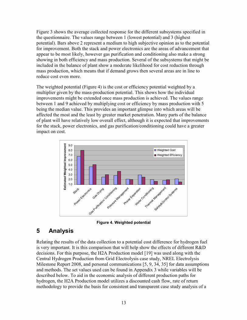
Figure 3 shows the average collected response for the different subsystems specified in the questionnaire. The values range between 1 (lowest potential) and 3 (highest potential). Bars above 2 represent a medium to high subjective opinion as to the potential for improvement. Both the stack and power electronics are the areas of advancement that appear to be most likely, however gas purification and conditioning also make a strong showing in both efficiency and mass production. Several of the subsystems that might be included in the balance of plant show a moderate likelihood for cost reduction through mass production, which means that if demand grows then several areas are in line to reduce cost even more.
The weighted potential (Figure 4) is the cost or efficiency potential weighted by a multiplier given by the mass-production potential. This shows how the individual improvements might be extended once mass production is achieved. The values range between 1 and 9 achieved by multiplying cost or efficiency by mass production with 5 being the median value. This provides an important glimpse into which areas will be affected the most and the least by greater market penetration. Many parts of the balance of plant will have relatively low overall effect, although it is expected that improvements for the stack, power electronics, and gas purification/conditioning could have a greater impact on cost.
Estim
ated
Wei
ghte
d Im
prov
emen
t
9.0
8.0 7.0
6.0
5.0 4.0
3.0 2.0
1.0
Weighted Cost
Weighted Efficiency
Figure 4. Weighted potential
Analysis
Relating the results of the data collection to a potential cost difference for hydrogen fuel is very important. It is this comparison that will help show the effects of different R&D decisions. For this purpose, the H2A Production model [19] was used along with the Central Hydrogen Production from Grid Electrolysis case study, NREL Electrolysis Milestone Report 2008, and personal communications [5, 9, 34, 35] for data assumptions and methods. The set values used can be found in Appendix 3 while variables will be described below. To aid in the economic analysis of different production paths for hydrogen, the H2A Production model utilizes a discounted cash flow, rate of return methodology to provide the basis for consistent and transparent case study analysis of a
13

variety of hydrogen production technologies. The main aspects considered from the data are the capital cost and efficiency. The isolated effect of mass production was not considered, but its possible effect was used to help determine scenarios for cost.
5.1 H2A Parameters In practice, the H2A Production model considers a wide variety of technical and economic parameters used together to perform an economic analysis of the hydrogen cost. The final cost of hydrogen ($/kg) is broken down into various components. Due to the nature of the study and data collected, this focus is on capital costs, feedstock costs, and operating and maintenance (O&M) costs.
Three plant sizes were chosen based upon a previous study [5] which included 10 kg/day, 100 kg/day, and 1,000 kg/day corresponding to small neighborhood, small forecourt, and forecourt installation sizes, respectively. The price of electricity and capital cost are the most significant factors in the cost of hydrogen from electrolysis. At large and small installation sizes, the significance of electricity and capital cost in the cost of hydrogen are reversed. For the larger sizes (1,000 kg/day - forecourt) electricity is the biggest factor, amounting to more than 62% of the total cost, and capital costs could be closer to 30%. This trend is nearly reversed at the smaller sizes (10 kg/day – small neighborhood), for which capital cost has the biggest effect at 62% of the final cost, with electricity cost at 20% [5]. For a better picture of the impacts these three installation sizes were considered.
Capital and electricity feedstock costs were of primary interest because they generally are the largest cost components of the overall cost. Alternatively demineralized water material input using standard H2A assumptions ($0.0049962/gal water) amounted to about $0.01/kg of hydrogen affecting the overall cost of hydrogen almost insignificantly. However, it should be noted that the availability or cost of producing of input water could be a significant deployment issue and is geographically dependent.
Standard H2A assumptions also were used to provide rough values for the fixed operating and maintenance (O&M) costs. The resultant simulations reflect how these three components, capital, feedstock, and fixed O&M, are affected by changes in capital cost or efficiency. A plant capacity factor of 97% was used. This factor significantly affects the depreciated capital costs as a low capacity factor means decreased production. It is expected, however, that due to their high capital investment the electrolyzers would be run as often as possible. Electrolyzers in use by other industries generally are reliable and capable of high capacity factors when supplied with adequate electricity. A value of 97% therefore was considered consistent with other studies of electrolyzers. However, a different application, such as filling stations or in conjunction with a variable source, could have a significantly lower capacity factor due to other constraints. This is greatly dependent upon the source of electricity, capacity of storage, and distribution of use. The capacity factor has a significant effect on the overall cost of hydrogen due to the significant capital investment required but its effect is left to future study.
Within the H2A Production model framework, the capital cost is a depreciated value calculated using a standard economic model called MACRS (Modified Accelerated Cost
14

Recover System), which also is an H2A default. All H2A default values were used in the financial input values where available, and auxiliary capital costs were collected from a Central Hydrogen Production from Grid Electrolysis case study performed by the H2A group and from personal communication [9, 34, 35]. These auxiliary costs were percentages based upon the electrolyzer capital cost. The particular assumptions taken can be seen in Appendix 3. The capital cost for each size level was scaled using equation 1 from the Electrolysis Milestone Report [5], where y equals the capital cost of the electrolyzer in thousand dollars and x equals kg H2/hr. The authors of the Electrolysis Milestone Report find a high correlation between electrolyzer capital cost and the collected costs from literature and vendor survey and it is accurate for the size ranges between 0.1 kg/hr and 100 kg/hr which fall into the sizes ranges being examined here.
0.6156y = 224.49x (1)
The capital costs used are shown in Table 2. The cost per kW is based upon a 53% efficiency based on the lower heating value (LHV) or 63% based on the higher heating value (HHV) equal to an electrical input of 62.8 kWh/kg of hydrogen. It is included to show the approximate cost levels being used. This baseline efficiency of 63% (HHV) is based upon company response and literature search, it is also used for calculating the electricity costs of running the units. These capital costs could represent PEM systems for the smaller installation sizes or alkaline at the medium to larger sizes. The data generalizations enable broader conclusions to be found.
Table 2. Capital Costs Used in H2A Analysis
Installation Size X Variable Electrolyzer Capital Cost
Electrolyzer Capital Cost
10 kg/day 0.42 kg/h $131,604 ~$5,000/kW 100 kg/day 4.2 kg/h $543,087 ~$2,000/kW 1,000 kg/day 42 kg/h $2,241,141 ~$850/kW
5.2 Capital Cost Sensitivity 5.2.1 Stack Cost Reduction In the company responses, the stack was found to be the overwhelming single most costly element, as well as being the component with greatest overall potential for improvement in both cost and efficiency. The stack was highly rated as being positively benefited by mass-production methods (see Figure 1, Figure 3, Figure 4).
To show an offset of possible cost scenarios, a study from Giner Electrochemical Systems (working under a U.S. DOE contract) was utilized [16]. One of the outcomes of this was identifying possible paths towards reducing the cost of the stack in their particular PEM electrolyzer configuration. Giner determined that reducing the number of individual parts within the stack element provided a twofold benefit: The cost was reduced due to fewer pieces, and the ease of mass production was increased due to a simplified design. Giner also studied changes in material plating of the electrodes from both a material-type standpoint and catalyst loading-factor standpoint. Giner’s estimation of the cost reduction due to the simplified design and high-volume production was
15

greater than 40% from a current approximation of $1,000/kW. The simplified design alone had reduced the stack cost in 2001 from $2,500/kW to less than $1,000/kW in 2007. Using this as a basis for what generally might be possible, a high reduction of 40% and a low reduction of 10% were used in this study for the cost-reduction potential of the stack. Combining this with the company response for the percentage of cost from the stack provided new capital-cost figures—high and low—for each size installation. The PEM cost breakdown was used for the simulation; however results could be similarly calculated based upon the alkaline breakdown. The analyses would be very similar therefore only one is shown.
Table 3. Capital Cost Range with Stack Cost Reductions
Installation Size
% Total Cost—Stack
Electrolyzer Capital Cost
Capital Cost with 40% Stack Cost
Reduction
Capital Cost with 10% Stack Cost
Reduction 10 kg/day 46% $131,604 $107,389 $125,550
100 kg/day 46% $543,087 $443,159 $518,105 1,000 kg/day 46% $2,241,141 $1,828,771 $2,138,049
The results of our cost analysis using the H2A model show that, even with high capital cost reduction, the total depreciated capital costs are much less and the cost reduction in the price of hydrogen is still less. Table 3 shows the capital costs incurred by reducing the stack portion of the capital cost (46%) by 40% and 10%. The results for 10 kg/day, 100 kg/day, and 1,000 kg/day using the capital costs from Table 3 can be seen in Figure 5 and Table 4, Figure 6 and Table 5, and Figure 7 and Table 6, respectively. The costs are the results of our analysis using the H2A Production model, and the percentage reductions merely show the percent differences from the base case. Table 4, for instance, shows the 40% cost reduction of the stack leads to an 18.2% reduction of the capital costs (compared to the base case) but only a 14.1% reduction of the total hydrogen cost of this case. There is a diminishing effect because the cost reduction is only coming from the stack, 46% of the electrolyzer cost; the capital cost is depreciated so the effect is not one-to-one to the hydrogen cost; and the total cost of hydrogen also is related to the cost of electricity, which is not affected by the capital-cost reduction. There is cost reduction seen in the fixed O&M portion of the cost of hydrogen, mainly due to that portion being proportional to the capital cost.
16

8.57 7.01 8.18
3.46 3.46
3.46
3.29
2.69 3.14
0.00
2.00
4.00
6.00
8.00
10.00
12.00
14.00
16.00
18.00
Base Case 40% Stack Cost Reduction
10% Stack Cost Reduction
Hyd
roge
n Co
st ($
/kg)
Fixed O&M Electricity Cost Depreciated Capital Cost
Figure 5. H2A analysis reduction of stack cost for 10 kg/day
Table 4. Data Table for Reduction of Stack Cost for 10 kg/Day
10 kg/Day Base Case
40% Stack Reduction
10% Stack Reduction
Capital Cost ($/kg) 8.57 7.01 8.18 Electricity Cost ($/kg) 3.46 3.46 3.46 Fixed O&M ($/kg) 3.29 2.69 3.14 Total ($/kg) 15.33 13.17 14.79 Capital Reduction (%) 18.2 4.6 Total Reduction (%) 14.1 3.5
3.59 2.95 3.43
3.46 3.46
3.46
1.36 1.11
1.30
0.00
1.00
2.00
3.00
4.00
5.00
6.00
7.00
8.00
9.00
Base Case 40% Stack Cost Reduction
10% Stack Cost Reduction
Hydr
ogen
Cos
t ($/
kg)
Fixed O&M Electricity Cost Depreciated Capital Cost
Figure 6. H2A analysis reduction of stack cost for 100 kg/day
17

Table 5. Data Table for Reduction of Stack Cost for 100 kg/Day
100 kg/Day Base Case
40% Stack Reduction
10% Stack Reduction
Capital Cost ($/kg) 3.59 2.95 3.43 Electricity Cost ($/kg) 3.46 3.46 3.46 Fixed O&M ($/kg) 1.36 1.11 1.30 Total ($/kg) 8.42 7.52 8.19 Capital Reduction (%) 17.9 4.5 Total Reduction (%) 10.7 2.7
1.53 1.27 1.47
3.46 3.46 3.46
0.56 0.46
0.54
0.00
1.00
2.00
3.00
4.00
5.00
6.00
Base Case 40% Stack Cost Reduction
10% Stack Cost Reduction
Hyd
roge
n Co
st ($
/kg)
Fixed O&M Electricity Cost Depreciated Capital Cost
Figure 7. H2A analysis reduction of stack cost for 1,000 kg/day
Table 6. Data Table for Reduction of Stack Cost for 1,000 kg/Day
1,000 kg/Day Base Case
40% Stack Reduction
10% Stack Reduction
Capital Cost ($/kg) 1.53 1.27 1.47 Electricity Cost ($/kg) 3.46 3.46 3.46 Fixed O&M ($/kg) 0.56 0.46 0.54 Total ($/kg) 5.56 5.19 5.47 Capital Reduction (%) 17.3 4.3 Total Reduction (%) 6.7 1.6
For comparison sake the PEM cost breakdown was used for all three system sizes. However, it might be more realistic to show the cost reduction of an alkaline system for the 1000 kg/day system. In general the larger systems are more represented by alkaline chemistry than PEM. So for comparison of the 1000 kg/day system if using the cost breakdown in Figure 2 which represents the average response of alkaline manufacturers who participated in the survey the stack cost reductions would result in a 8.2% reduction
18

19
for the cost of hydrogen in the 40% stack reduction case and 2.1% reduction in cost of hydrogen for the 10% stack reduction case. The alkaline stack represented 57% of the cost versus 46% of the PEM cost. These numbers can be compared with total reduction percentage in Table 6 which uses the PEM cost breakdown for the analysis.
An examination of the data between the three size categories being explored reveals that at the smaller size, 10 kg/day, the capital cost reduction has a greater effect on the total hydrogen cost because the capital cost and fixed O&M cost are more significant components of the total cost. If electricity has a greater impact on the cost, then reducing the capital investment is much less effective. The results show that even a fairly large reduction of the stack cost has a diminished effect on the depreciated cost. As expected, the smaller systems—where capital cost is a dominating factor—are more affected by the capital-cost reduction than are the large systems.
5.2.2 Power Electronics Cost Reduction The power electronics subsystem in electrolyzers constitutes the second largest component cost within the unit. To see the possible effect of cost reduction in this area, a second set of simulations was run. Again, company response suggested a medium to high level of expectation that cost could be reduced for this component. Using this as a basis, two cases of high- and low-development cost reductions were considered. The capital costs used can be seen in Table 7, which shows that the power electronics portion of the cost (22% from Figure 1) is reduced by 20% and 5% to provide the given values.
Table 7. Capital Cost Range with Power Electronics Cost Reductions
Installation Size
% Total Cost—Power Electronics
Capital Cost
Capital Cost with 20% Power
Electronics Cost Reduction
Capital Cost with 5% Power
Electronics Cost Reduction
10 kg/day 22% $131,604 $125,813 $130,156 100 kg/day 22% $543,087 $519,191 $537,113
1,000 kg/day 22% $2,241,141 $2,142,531 $2,216,489
The power electronics component is a smaller piece of the system cost pie (Figure 1), therefore the effect of the improvement is smaller than that for the stack. As in the previous case, only the capital cost is being adjusted to perform the calculation. There is a reduction in the overall cost of hydrogen, but the depreciated capital cost and the cost of hydrogen is much less impacted. Results for 10 kg/day, 100 kg/day, and 1,000 kg/day are shown in Figure 8 and Table 8, Figure 9 and Table 9, and Figure 10 and Table 10, respectively. Similarly to the tables presented above, the following tables show the effect that a reduction of power electronics cost would have on the overall cost of hydrogen. In this study, the power electronics are assumed to account for 22% of the total cost, there-fore the effect of a reduction is less. The capital reduction percentage (Table 8, Table 9, Table 10) shows the percent reduction compared to the base case. For the 10 kg/day case, a 20% reduction of the power electronics cost will reduce the depreciated capital-cost component of the cost of hydrogen by 4.4% and the total reduction for the cost of

hydrogen will be 3.3%. As with the stack reduction scenario, the capital cost reduction is most effective where capital cost and fixed O&M (a portion of the capital cost) are the greater components of the total cost of hydrogen which is seen in the smaller sizes.
8.57 8.19 8.47
3.46 3.46 3.46
3.29 3.15 3.26
0.00
2.00
4.00
6.00
8.00
10.00
12.00
14.00
16.00
18.00
Base Case 20% Power Electronics Cost
Reduction
5% Power Electronics Cost
Reduction
Hydr
ogen
Cos
t ($/
kg)
Fixed O&M Electricity Cost Depreciated Capital Cost
Figure 8. H2A analysis reduction of power electronics cost for 10 kg/day
Table 8. Data Table for Reduction of Power Electronics Cost for 10 kg/Day
10 kg/Day Base Case
20% Power Electronics
Cost Reduction
5% Power Electronics
Cost Reduction Capital Cost ($/kg) 8.57 8.19 8.47 Electricity Cost ($/kg) 3.46 3.46 3.46 Fixed O&M ($/kg) 3.29 3.15 3.26 Total ($/kg) 15.33 14.82 15.20 Capital Reduction (%) 4.4 1.1 Total Reduction (%) 3.3 0.8
20

9.00
8.00
7.00
6.00
5.00
3.59
3.46
1.36
3.43
3.46
1.30
3.55
3.46
1.34
Hydr
ogen
Cos
t ($/
kg)
Fixed O&M Electricity Cost
4.00 Depreciated Capital Cost
3.00
2.00
1.00
0.00 Base Case 20% Power 5% Power
Electronics Cost Electronics Cost Reduction Reduction
Figure 9. H2A analysis reduction of power electronics cost for 100 kg/day
Table 9. Data Table for Reduction of Power Electronics Cost for 100 kg/day
100 kg/Day Base Case
20% Power Electronics
Cost Reduction
5% Power Electronics
Cost Reduction Capital Cost ($/kg) 3.59 3.43 3.55 Electricity Cost ($/kg) 3.46 3.46 3.46 Fixed O&M ($/kg) 1.36 1.30 1.34 Total ($/kg) 8.42 8.20 8.36 Capital Reduction (%) 4.3 1.1 Total Reduction (%) 2.6 0.7
1.53 1.47 1.52
3.46 3.46 3.46
0.56 0.54 0.55
0.00
1.00
2.00
3.00
4.00
5.00
6.00
Base Case 20% Power Electronics Cost
Reduction
5% Power Electronics Cost
Reduction
Hydr
ogen
Cos
t ($/
kg)
Fixed O&M Electricity Cost Depreciated Capital Cost
Figure 10. H2A analysis reduction of power electronics cost for 1,000 kg/day
21

Table 10. Data Table for Reduction of Power Electronics Cost for 1,000 kg/Day
1,000 kg/Day Base Case
20% Power Electronics
Cost Reduction
5% Power Electronics
Cost Reduction Capital Cost ($/kg) 1.53 1.47 1.52 Electricity Cost ($/kg) 3.46 3.46 3.46 Fixed O&M ($/kg) 0.56 0.54 0.55 Total ($/kg) 5.56 5.47 5.54 Capital Reduction (%) 4.1 1.0 Total Reduction (%) 1.6 0.4
As above the 1000 kg/day system could be represented by the alkaline cost breakdown. The power electronics component reduction if using the alkaline cost breakdown from Figure 2 results in a 2.0% reduction in the cost of hydrogen for the 20% power electronics reduction case and 0.3% reduction in the cost of hydrogen for the 5% reduction case. These could be compared with Table 10 which uses the PEM cost breakdown instead.
For this particular scenario, where the electrolyzers are running at a high load factor (i.e. 97% up time), the capital-cost reductions have significant but diminishing effect as size increases, due to a scaled capital cost which is greater at smaller sizes. If the load factor was reduced, such as in some renewable hydrogen systems, however, this could affect the significance of the capital-cost factor even at larger sizes.
5.3 Efficiency Improvement SensitivityImprovements in system efficiency have a direct effect on the cost of hydrogen due to the input electricity required. The system efficiency directly relates to how much energy it takes to electrolyze water into hydrogen and oxygen. To see the potential effects the three cases from above are utilized. The initial capital costs were kept constant, but the initial system efficiency of 63% (HHV; 53% LHV) was varied. Referring to the Giner study, PEM electrolyzers realistically could attain a system efficiency of 85% (HHV) [16] or 72% (LHV).
One method that the H2A Production model uses to calculate the electricity usage is by entering the conversion efficiency for the feedstock using the lower heating value (LHV) of hydrogen, although it should be noted that to reduce confusion the HHV of hydrogen should be used instead. When using the LHV it should always be recognized that 82% efficiency is the maximum achievable, while the HHV is based on the more common maximum of 100%. Three cases were developed for the three installation sizes. The capital costs are taken as shown in Table 1, and the other factors are provided in Table 11. To help reduce confusion, the effect of different efficiency levels is shown with the actual required energy input (kWh/kg).
22

Table 11. PEM Efficiency Scenarios for H2A
53%(LHV) System
Efficiency (Base Case)
63% (LHV) System Efficiency
(Medium Improvement)
73% (LHV) System Efficiency
(High Improvement) Electricity ($(2005)/kWh) 0.05 0.05 0.05 Energy Input (kWh/kg) 62.9 52.9 45.7
The results provide an additional area to focus upon to attain cost reductions. At smaller installation sizes the capital cost dominates, but in larger installations electricity cost is the biggest factor. Efficiency most directly affects this cost; therefore greater reductions are seen at the bigger installation sizes for increasing efficiency. These are compared for 10 kg/day, 100 kg/day, and 1,000 kg/day in Figure 11 and Table 12, Figure 12 and Table 13, and Figure 13 and Table 14 respectively. As opposed to the capital-cost reductions presented above, in this case the efficiency has a more direct effect to the electricity feedstock costs. Greater efficiency means that less electricity is needed to run the electrolyzer units, and a reduced cost of hydrogen. In the three cases used here, energy input is decreased from the base case of 62.9 kWh/kg to 52.9 kWh/kg and 45.7 kWh/kg which corresponds to efficiency improvements of 10% and 20% (LHV; or 12% and 24% HHV). The electricity cost reduction percentage presents how much a reduction the efficiency increase had on the electricity component of the cost of hydrogen. The total cost reduction shows the effect for the total cost. In the 10 kg/day case, for instance, an increase to 63% efficiency (LHV) of the electrolyzer results in a 15.9% reduction in electricity cost and a 3.7% reduction in the total cost of hydrogen.
In the cases where the electrolyzers are running at 97% up time, electricity costs are the dominating factor at larger sizes. At 1,000 kg/day the 10% increase in efficiency from baseline can affect the total cost of hydrogen by 10.1% (Table 14). This is a more direct effect than the depreciated capital costs, and is especially noticeable at larger sizes where electricity cost is the bigger determinant in the cost of hydrogen.
23

8.57 8.55 8.54
3.46 2.91 2.51
3.29 3.29 3.29
0.00
2.00
4.00
6.00
8.00
10.00
12.00
14.00
16.00
18.00
53% Efficiency 63% Efficiency 73% Efficiency
Hydr
ogen
Cos
t ($/
kg)
Fixed O&M Electricity Cost Depreciated Capital Cost
Figure 11. H2A analysis cost effects of increasing efficiency for 10 kg/day
Table 12. Data Table for Cost Effects of Increasing Efficiency for 10 kg/Day
10 kg/day
53% (LHV) System
Efficiency
63% (LHV) System
Efficiency
73% (LHV) System
Efficiency Capital ($/kg) 8.57 8.55 8.54 Electricity ($/kg) 3.46 2.91 2.51 Fixed O&M ($/kg) 3.29 3.29 3.29 Total ($/kg) 15.33 14.77 14.36 Electricity Cost Reduction (%) 15.9 27.4 Total Cost Reduction (%) 3.7 6.3
24

3.59 3.57 3.56
3.46 2.91
2.51
1.36
1.36 1.36
0.00
1.00
2.00
3.00
4.00
5.00
6.00
7.00
8.00
9.00
53% Efficiency 63% Efficiency 73% Efficiency
Hyd
roge
n Co
st ($
/kg)
Fixed O&M Electricity Cost Depreciated Capital Cost
Figure 12. H2A analysis cost effects of increasing efficiency for 100 kg/day
Table 13. Data Table for Cost Effects of Increasing Efficiency for 100 kg/Day
100 kg/Day
53% (LHV) System
Efficiency
63% (LHV) System
Efficiency
73% (LHV) System
Efficiency Capital ($/kg) 3.59 3.57 3.56 Electricity ($/kg) 3.46 2.91 2.51 Fixed O&M ($/kg) 1.36 1.36 1.36 Total ($/kg) 8.42 7.85 7.44 Electricity Cost Reduction (%) 15.9 27.4 Total Cost Reduction (%) 6.8 11.6
25
0.00
1.00
2.00
3.00
4.00
5.00
6.00
53% Efficiency 63% Efficiency 73% Efficiency
Hyd
roge
n Co
st ($
/kg)
Fixed O&M Electricity Cost Depreciated Capital Cost
1.53 1.52 1.51
3.46 2.91
2.51
0.56
0.56
0.56
Figure 13. H2A analysis cost effects of increasing efficiency for 1,000 kg/day
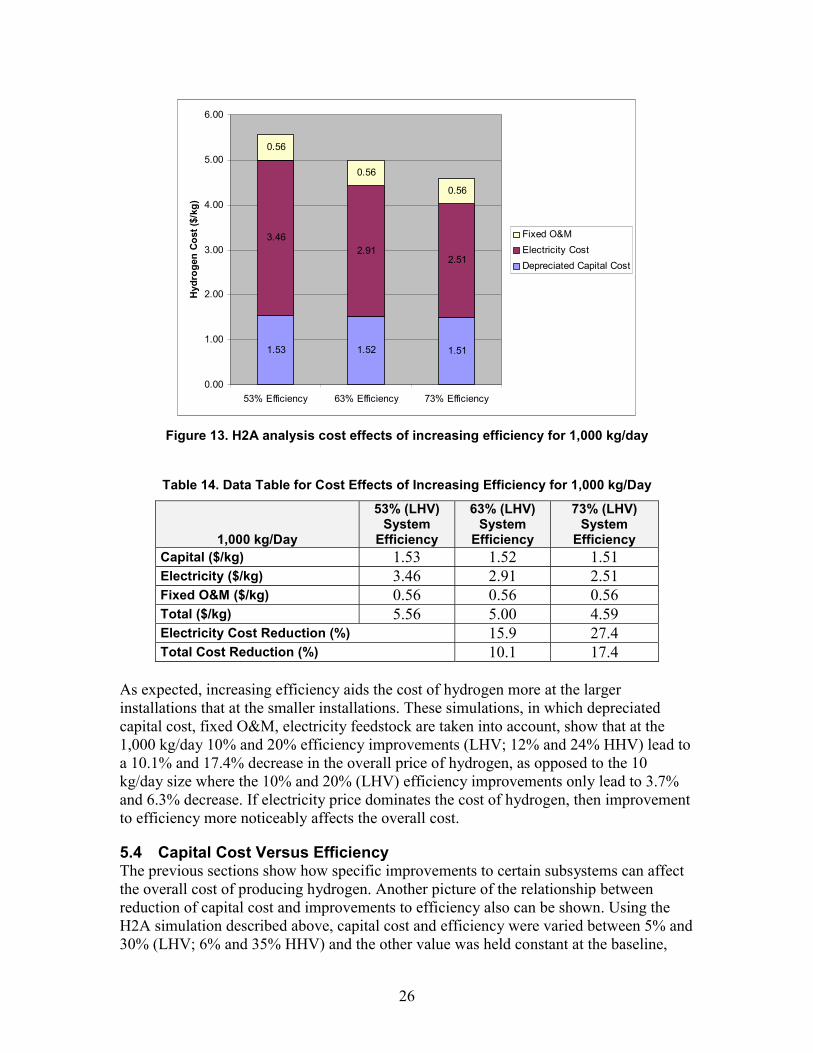
Table 14. Data Table for Cost Effects of Increasing Efficiency for 1,000 kg/Day
1,000 kg/Day
53% (LHV) System
Efficiency
63% (LHV) System
Efficiency
73% (LHV) System
Efficiency Capital ($/kg) 1.53 1.52 1.51 Electricity ($/kg) 3.46 2.91 2.51 Fixed O&M ($/kg) 0.56 0.56 0.56 Total ($/kg) 5.56 5.00 4.59 Electricity Cost Reduction (%) 15.9 27.4 Total Cost Reduction (%) 10.1 17.4
As expected, increasing efficiency aids the cost of hydrogen more at the larger installations that at the smaller installations. These simulations, in which depreciated capital cost, fixed O&M, electricity feedstock are taken into account, show that at the 1,000 kg/day 10% and 20% efficiency improvements (LHV; 12% and 24% HHV) lead to a 10.1% and 17.4% decrease in the overall price of hydrogen, as opposed to the 10 kg/day size where the 10% and 20% (LHV) efficiency improvements only lead to 3.7% and 6.3% decrease. If electricity price dominates the cost of hydrogen, then improvement to efficiency more noticeably affects the overall cost.
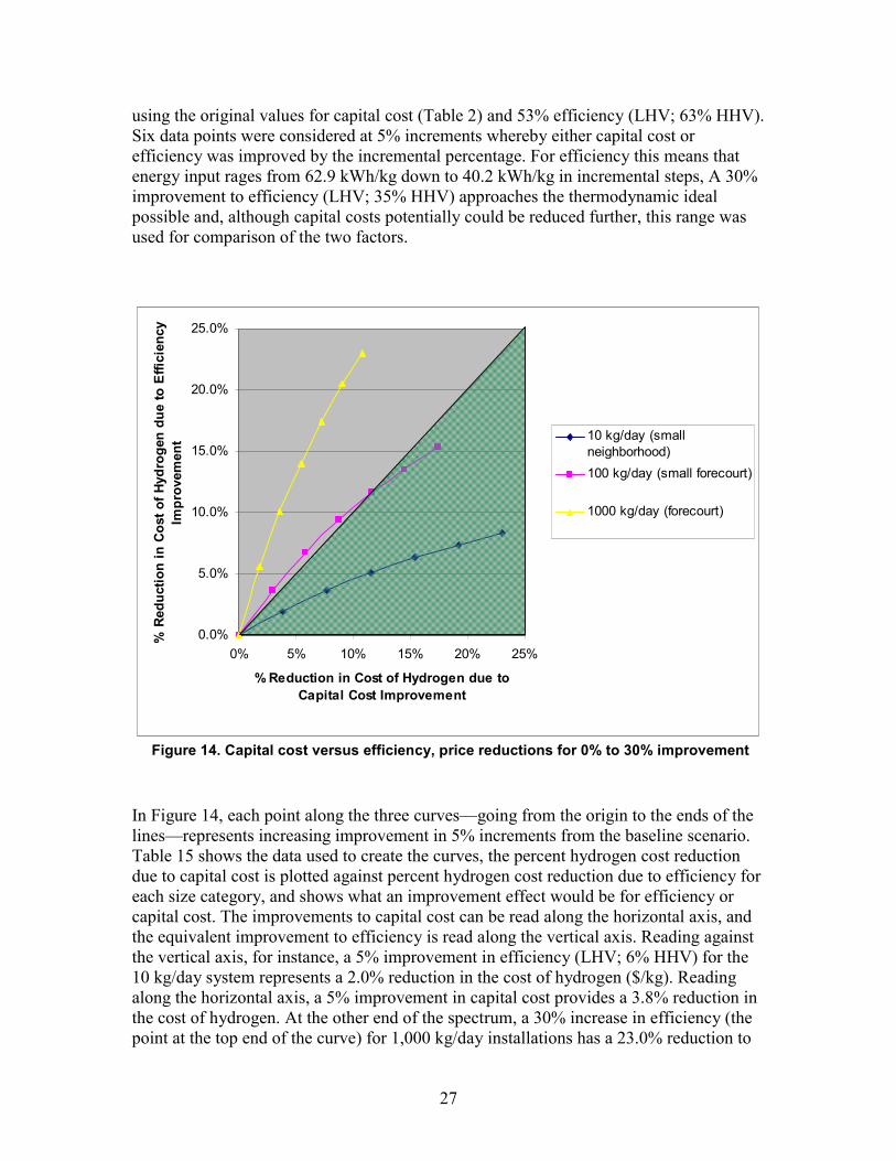
5.4 Capital Cost Versus EfficiencyThe previous sections show how specific improvements to certain subsystems can affect the overall cost of producing hydrogen. Another picture of the relationship between reduction of capital cost and improvements to efficiency also can be shown. Using the H2A simulation described above, capital cost and efficiency were varied between 5% and 30% (LHV; 6% and 35% HHV) and the other value was held constant at the baseline,
26
0% 5% 10% 15% 20% 25%
% Reduction in Cost of Hydrogen due to Capital Cost Improvement
% R
educ
tion
in C
ost o
f Hyd
roge
n du
e to
Effi
cien
cy
Impr
ovem
ent
using the original values for capital cost (Table 2) and 53% efficiency (LHV; 63% HHV). Six data points were considered at 5% increments whereby either capital cost or efficiency was improved by the incremental percentage. For efficiency this means that energy input rages from 62.9 kWh/kg down to 40.2 kWh/kg in incremental steps, A 30% improvement to efficiency (LHV; 35% HHV) approaches the thermodynamic ideal possible and, although capital costs potentially could be reduced further, this range was used for comparison of the two factors.
25.0%
20.0%
10 kg/day (small 15.0% neighborhood)
100 kg/day (small forecourt)
1000 kg/day (forecourt)10.0%
5.0%
0.0%
Figure 14. Capital cost versus efficiency, price reductions for 0% to 30% improvement
In Figure 14, each point along the three curves—going from the origin to the ends of the lines—represents increasing improvement in 5% increments from the baseline scenario. Table 15 shows the data used to create the curves, the percent hydrogen cost reduction due to capital cost is plotted against percent hydrogen cost reduction due to efficiency for each size category, and shows what an improvement effect would be for efficiency or capital cost. The improvements to capital cost can be read along the horizontal axis, and the equivalent improvement to efficiency is read along the vertical axis. Reading against the vertical axis, for instance, a 5% improvement in efficiency (LHV; 6% HHV) for the 10 kg/day system represents a 2.0% reduction in the cost of hydrogen ($/kg). Reading along the horizontal axis, a 5% improvement in capital cost provides a 3.8% reduction in the cost of hydrogen. At the other end of the spectrum, a 30% increase in efficiency (the point at the top end of the curve) for 1,000 kg/day installations has a 23.0% reduction to
27

cost of hydrogen ($/kg), and 30% improvement to capital cost only will affect the cost by 10.8%. The intermediate size—for which the same improvements to either efficiency or capital cost are nearly equivalent—lies between the 10 kg/day and 100 kg/day installation size, where the slope is 1 and equivalent improvements to capital cost or efficiency garner the same effect for the cost of hydrogen. Curves and data in the green section of Figure 14 will have the most benefit to the cost of hydrogen by reduction of capital cost than the same reduction in efficiency. Systems above the green will show greater cost of hydrogen improvement by increases in efficiency. As can be seen the 100 kg/day electrolyzer system corresponds to the approximate break-even line where the same percentage improvement in capital cost or efficiency will have the about the same effect on the cost of hydrogen.
Table 15. Data for Price Reductions with 0% to 30% Improvement, Capital Cost Versus Efficiency
Improvement
[Efficiency based on
LHV]
10 kg/day 100 kg/day 1,000 kg/day Percent
Hydrogen Cost
Reduction Due to Capital Cost
Percent Hydrogen
Cost Reduction
Due to Efficiency
Percent Hydrogen
Cost Reduction
Due to Capital Cost
Percent Hydrogen
Cost Reduction
Due to Efficiency
Percent Hydrogen
Cost Reduction
Due to Capital Cost
Percent Hydrogen
Cost Reduction
Due to Efficiency
0% 0.0% 0.0% 0.0% 0.0% 0.0% 0.0% 5% 3.8% 2.0% 2.9% 3.7% 1.8% 5.6%
10% 7.7% 3.7% 5.8% 6.8% 3.6% 10.1% 15% 11.5% 5.1% 8.7% 9.4% 5.4% 14.0% 20% 15.3% 6.3% 11.6% 11.6% 7.2% 17.4% 25% 19.2% 7.4% 14.5% 13.5% 9.0% 20.5% 30% 23.0% 8.3% 17.4% 15.3% 10.8% 23.0%
While capital cost potentially could be improved to a greater than a 30% reduction, efficiency improvements are more limited. There is an upper limit to efficiency based upon thermodynamic principles which cap the top efficiency of a system. Once this near-ideal efficiency is reached, hydrogen cost improvements only could come from other areas. The capital cost of electrolyzers could be reduced more than is shown. The Giner study anticipated possible capital-cost reductions from between $1,000/kW and $600/kW—a 40% reduction.[16] Another study suggested a future scenario of improvements from $1,000/kW to $125/kW in the next 15 to 20 years—an almost 90% reduction [36]. These improvements would be extensions of the lines seen above, assuming that the other factors are held constant.
It is important to note that these percentages are only rough figures based upon scaled capital cost, fixed O&M being percentages of the capital cost, and the electricity feedstock resultant from efficiency assumptions. There could be other auxiliary costs which also affect the overall cost that have not been included. Because electricity and capital costs are the dominant factors, however, even these rough estimates can be used to get a sense of how the cost of hydrogen is affected by various improvements.
28

6 Conclusion
Electrolyzer manufacturer response regarding the cost breakdown of different system components and their expert opinions regarding the likelihood for improvement was used to run H2A Production model case study simulations. This was done to determine roughly how the cost of hydrogen would be affected at different installation sizes if various improvements were made. These improvements might come directly in capital-cost reduction of some component of the electrolyzer or in system efficiency improvement. In the analysis, three topics were considered: (1) size scaled capital costs, (2) fixed O&M proportional to capital cost, and (3) electricity feedstock. The analysis was conducted using the standard H2A Production model defaults along with the Central Hydrogen Production from Grid Electrolysis case study and personal communication assumptions as listed in Appendix 3. The particular parameters being compared here were uninstalled capital costs and the electricity usage calculated from electrolyzer system efficiency and how these affected the breakdown of cost of hydrogen over the lifetime of a hydrogen production plant. Several production capacities were considered to highlight different capital cost levels that might be found at those sizes.
The H2A Production model case study analysis focused on the component cost of electrolyzer stacks and power electronics as well as the effects of system efficiency on the electricity costs. A composite analysis of the relationship between capital cost and efficiency also was performed to examine the rate of change of those to the rate of change of the cost of hydrogen by their improvement. The stack and power electronics subsystems were chosen because they represent the greatest component costs in the electrolyzer unit. Examination of how specific reductions to these subsystems affect the total cost provides a clearer picture of how component improvements affect the cost of hydrogen. The interrelationship between capital cost and efficiency also is important to the cost of hydrogen, because, in some cases, an efficiency improvement could increase capital cost. For some systems this exchange between capital cost and efficiency might improve hydrogen cost. So by examining the rate of change to the cost of hydrogen from either capital cost reduction or efficiency improvement it can be better analyzed the worth of a particular kind of system improvement. Finding the balance between these two factors can help determine where the best potential for improvement exists.
The analysis showed that, in the smaller systems (10 kg/day and not more than 100 kg/day), the capital costs dominate the cost of hydrogen; although significant capital-cost improvements would be needed to have a major effect. The most likely path to reducing the cost of hydrogen is to focus on stack costs and pursue simplified designs of all subsystems, making them better suited to mass production. In general, reduction of capital costs is dampened when analyzed in a depreciating cost model. The effects of capital-cost reduction are lessened after the amount has been depreciated and included in the cost of hydrogen breakdown. For systems having high capital cost, this might be the most advantageous way to reduce the cost of hydrogen. Additionally, the reduction of electrolyzer capital cost could open the favorable avenues for renewably sourced hydrogen from electrolysis [36].
29

For larger systems (100 kg/day to 1,000 kg/day), the biggest contributor to the hydrogen cost is the electricity feedstock. In the case analyzed, better overall system efficiency reduces the amount of electrical energy needed to produce the same amount of hydrogen. A reduction in electricity feedstock cost has significant beneficial effects on the cost of hydrogen. For the largest 1,000 kg/day systems, a 5% increase in efficiency reduced the cost of hydrogen by more than 5%. The electricity cost reductions achieved through efficiency improvements can be quite significant, especially in systems where the electricity cost dominates the cost of hydrogen. The effects of capital costs have a diminished effect when analyzed through a depreciated cost model. Over the lifetime of the system the sensitivity of the capital cost to the total cost is less than the sensitivity of efficiency to the total cost. Increased capital cost therefore can be justified when it improves efficiency. The deciding factor is the resultant contribution to the total cost of hydrogen. In systems where depreciated capital cost dominates, the capital-cost reduction has a greater effect; where electricity dominates, efficiency has a greater effect. In the scenarios investigated, the smaller systems were impacted more significantly by capital costs, and the larger size installations were more affected by electricity cost. The tipping point in the analysis is where the depreciated capital plus O&M and electricity feedstock costs are equal components of the cost of hydrogen. The shape and placement of the curves have a great deal to do with the capacity factors. Lower capacity factors will mean lower electricity use of the electrolyzer over the lifetime of the system. Therefore the points at which electricity cost and depreciated capital cost will be equal occur at different initial conditions. In this study the characteristics of the electrolyzer were near ideal using a high capacity factor that might be found in systems run round the clock. This is realistic for grid connected central distribution plant. However in other applications, such as the distributed generation of a filling station, the capacity factor might be somewhat lower which would decrease the electricity component of the hydrogen cost and increase the capital cost effect. This would impact whether electricity or capital costs dominate the cost of hydrogen. Understanding where these balance points in a system framework occur can help decrease the overall cost of hydrogen over the lifetime of a system.
The likely areas for greatest capital cost improvement in electrolyzers come in the stack and power electronics subsystems and from mass production. Hydrogen gas conditioning and purification subsystems also show promise. Many of the applications that electrolyzers are currently designed for (ammonia, industrial gas market, military, etc) are less cost sensitive. When placed in a more cost-sensitive market, such as transportation or electricity generation, there is much more opportunity for system streamlining and cost improvement. There are areas where costs can be reduced, although this should be balanced with efficiency improvement for installation in larger hydrogen-production facilities where electricity feedstock dominates the cost of hydrogen.
30

References
1. Gupta, V. Prospects of Hydrogen as an Energy Carrier for the Future, in Miami International Conference on Alternative Energy Sources, T.N. Veziroğlu, Editor. 1982, Elsevier: Amersterdam, Oxford, New York, Tokyo: Miami Beach, FL USA.
2. Chow, O. Cost Reduction of High Pressure Hydrogen Generation From Electrolysis. 2005, Hydrogen Technology Group, Proton, A Distributed Energy System Company.
3. Heiman, M.K.; Solomon, B.D. "Fueling U.S. Transportation: The hydrogen economy and its alternatives." Environment; Vol. 49(8), 2007; pp. 10-25.
4. Annual Energy Outlook 2008 (Revised Early Release). 2008.
5. NREL Electrolysis Milestone Report (pre-release). 2008.
6. Dutton, A.G.; Bleijs, J.A.M.; Dienhart, H.; Falchetta, M.; Hug, W.; Prischich, D.; Ruddell, A.J. "Experience in the design, sizing, economics, and implementation of autonomous wind-powered hydrogen production systems." International Journal of Hydrogen Energy; Vol. 25(8), 2000; pp. 705-722.
7. Kothari, R.; Buddhi, D.; Sawhney, R.L. "Studies on the effect of temperature of the electrolytes on the rate of production of hydrogen." International Journal of Hydrogen Energy; Vol. 30(3), 2005; pp. 261-263.
8. Turner, J.; Sverdrup, G.; Mann, M.K.; Maness, P.C.; Kroposki, B.; Ghirardi, M.; Evans, R.J.; Blake, D. "Renewable hydrogen production." International Journal of Energy Research; Vol. 32(5), 2008; pp. 379-407.
9. Harrison, K. Personal Communication. 2008.
10. OI, T.; Nakai, H.; Iio, M.; Sakaki, Y. "Conceptual design of large scale water electrolyzer using proton exchange membranes for peak shaving electricity." The National Hydrogen Association's 10th Annual Hydrogen Meeting; 7-9 April 1999, Vienna, Virginia, USA. National Hydrogen Association; pp.
11. Smith, A.F.G., Newborough, M. "Low-Cost Polymer Electrolysers and Electrolyser Implementation Scenarios for Carbon Abatement." Report to the Carbon Trust and ITM-Power PLC; Vol. 2004.
12. Suresh, B.S.; Yokose, K. CEH Marketing Research Report: Air Separation Gases, in Chemical Economics Handbook. 2005, SRI Consulting: Menlo Park, California.
13. Kroposki, B.; Levene, J.; Harrison, K.; Sen, P.K.; Novachek, F. Electrolysis: Information and Opportunities for Electric Power Utilities. 2006, NREL: Golden, CO. p. Size: 33 pp.
31

14. Konopka, A.; Gregory, D. "Hydrogen Production by Electrolysis: Present and Future." 10th Intersociety Energy Conversion Engineering Conference; 1975, IEEE Cat. No. 75CHO 983-7 TAB. pp.
15. "Avalence LLC: Technology." 2008 [cited March 11, 2008]; Available from: http://www.avalence.com/technology/default.asp.
16. Cropley, C.C.; Norman, T.J. Low-Cost High-Pressure Hydrogen Generator. 2008. p. Size: 25 pages.
17. "Hydrogen Posture Plan", U. DOE, Editor. 2006.
18. "DOE Record 5013:Hydrogen Cost Goal." 2005 [cited May 11, 2008]; Available from: http://www.hydrogen.energy.gov/pdfs/5013_h2_cost_goal.pdf.
19. "DOE Hydrogen Program: DOE H2A Analysis." 2008 [cited March 11, 2008]; Available from: http://www.hydrogen.energy.gov/h2a_analysis.html.
20. Greiner, C.J.; Korpås, M.; Holen, A.T. "A Norwegian case study on the production of hydrogen from wind power." International Journal of Hydrogen Energy; Vol. 32(10/11), 2007; pp. 1500-1507.
21. Hake, J.F.; Linssen, J.; Walbeck, M. "Prospects for hydrogen in the German energy system." Energy Policy; Vol. 34(11), 2006; pp. 1271-1283.
22. Mulder, G.; Hetland, J.; Lenaers, G. "Towards a sustainable hydrogen economy: Hydrogen pathways and infrastructure." International Journal of Hydrogen Energy; Vol. 32(10-11), 2007; pp. 1324-1331.
23. Hetland, J.; Mulder, G. "In search of a sustainable hydrogen economy: How a large-scale transition to hydrogen may affect the primary energy demand and greenhouse gas emissions." International Journal of Hydrogen Energy; Vol. 32(6), 2007; pp. 736-747.
24. Mueller-Langer, F.; Tzimas, E.; Kaltschmitt, M.; Peteves, S. "Techno-economic assessment of hydrogen production processes for the hydrogen economy for the short and medium term." International Journal of Hydrogen Energy; Vol. 32(16), 2007; pp. 37973810.
25. Linnemann, J.; Steinberger-Wilckens, R. "Realistic costs of wind-hydrogen vehicle fuel production." International Journal of Hydrogen Energy; Vol. 32(10/11), 2007; pp. 1492-1499.
26. Levene, J.; Kroposki, B.; Sverdrup, G. "Wind Energy and Production of Hydrogen and Electricity -- Opportunities for Renewable Hydrogen: Preprint." 2006, United States. pp. Size: 18 pp.
32

27. Paynter, R.J.H.; Lipman, N.H.; Foster, J.E. "The potential of hydrogen and electricity production from wind power." Rutherford Appleton Laboratory. Energy Research Unit; Vol. 1991.
28. Levene, J.I. Production of Hydrogen at the Forecourt Using Off-Peak Electricity: June 2005 (Milestone Report). 2007, NREL: Golden, CO. p. Size: 45 pp.
29. Kothari, R.; Buddhi, D.; Sawhney, R.L. "Comparison of environmental and economic aspects of various hydrogen production methods." Renewable & Sustainable Energy Reviews; Vol. 12(2), 2008; pp. 553-563.
30. Muljadi, E.; Wang, C.; Nehrir, M.H. "Parallel Operation of Wind Turbine, Fuel Cell, and Diesel Generation Sources: Preprint." 2004, United States. pp. Size: 9 pp. pages; Format: Adobe PDF Document with Extractable Text
31. Mills, A.; Al-Hallaj, S. "Simulation of hydrogen-based hybrid systems using Hybrid2." International Journal of Hydrogen Energy; Vol. 29(10), 2004; pp. 991-999.
32. Ulleberg, Ø.; Pryor, T.L. Optimization of Integrated Renewable Energy Hydrogen Systems in Diesel Engine Mini-Grid, in WHEC 2002 - 14th World Hydrogen Energy Conference. 9-14 June 2002: Montreal, Canada.
33. Levene, J.I. "US DOE Hydrogen Program: H2A Analysis - Hydrogen Generation from Wind v1.08." 2005 [cited May 11, 2008]; Available from: http://www.hydrogen.energy.gov/h2a_prod_studies.html.
34. Ramsden, T. "Current (2008) Hydrogen Production from Central Grid Electrolysis v 2.0.1." 2008 [cited; Available from: http://www.hydrogen.energy.gov/h2a_prod_studies.html.
35. Penev, M. Personal Communication. 2008.
36. Committee on, A.; Strategies for Future Hydrogen Use The Hydrogen Economy: Opportunities, Costs, Barriers, and R&D Needs. 2004. p. Size: 7,538 KB.
33

Appendix 1. Company Survey List
Company Website AccaGen http://www.accagen.com/ Available Energy http://www.availableenergy.com Avalence http://avalence.com/default.asp Electric Hydrogen (Eh!) http://www.electrichydrogen.com/ ELT Elektrolyse Technik http://www.elektrolyse.de/vkp/index.php Gesellschaft für Hochleistungsele
http://www.ghw-mbh.de/english/01_home/index.html
Giner http://www.ginerinc.com/ Hamilton Sundstrand http://www.hamiltonsundstrand.com Hydrogen Technology Ltd. http://www.hydrogentechnology.com.au/ Hydrogenics http://www.hydrogenics.com/onsite/products.asp Idroenergy http://www.idroenergy.it Industrie Haute Technologie http://iht.ch Infinity Fuel http://www.infinityfuel.com/ ITM http://www.itm-power.com/ Linde www.linde.com/hydrogen Lynntech http://www.lynntech.com/ Nitidor Clever http://nitidor.com/index.asp Peak Scientific http://www.peakscientific.com/ PIEL (ILT Tech.) http://www.piel.it/ Proton Energy Systems http://protonenergy.com/ Schmidlin-DBS http://www.schmidlin-dbs.com/ Siam Water Flame http://www.waterflame.co.th/ StatoilHydro Hydrogen Technologies
http://www.electrolysers.com/
Teledyne Energy Systems http://www.teledynees.com Treadwell http://www.treadwellcorp.com/ UTC Power http://www.utcpower.com
34

Appendix 2. Company Feedback Request
35

36

37

38

39

40

Appendix 3. H2A Assumed Parameters
Except where otherwise noted, the following values were collected from 01D_Current_Central_Hydrogen_Production_from_Grid_Electrolysis_version_2.0.1.xls [34].
Operating Capacity Factor (%) 97.0% Assumed Start-Up Year 2008 Length of Construction Period (Years) 1 [35] Percentage of Capital Spent in First Year of Construction 100% Start-Up Time (Years) 2 Plant Life (Years) 40 Analysis Period (Years) 40 Depreciation Schedule Length (Years) 20 Interest Rate on Debt, if Applicable (%) 0.00% Debt Period (Years) 0 Percentage of Fixed Operating Costs During Start-Up (%) 100% Percentage of Revenues During Start-Up (%) 50% Percentage of Variable Operating Costs During Start-Up (%) 75% Site Preparation ($) 1% capital cost Engineering and Design ($) 5% capital cost Project Contingency ($) 10% capital cost Up-Front Permitting Costs ($) 1% capital cost Production Maintenance and Repairs ($/Year) 5% capital cost [35] Installation Cost Factor 1.1 [9]
H2A default values were used where available. Additionally, feedstock prices were taken from the AEO 2007 lookup table for Industrial Electricity metric, $0.05/kWh (2005), using 53% conversion efficiency as automated in the H2A spreadsheet. Replacement costs were 30% of initial capital cost every 10 years of operation.
41

REPORT DOCUMENTATION PAGE Form Approved OMB No. 0704-0188
The public reporting burden for this collection of information is estimated to average 1 hour per response, including the time for reviewing instructions, searching existing data sources,gathering and maintaining the data needed, and completing and reviewing the collection of information. Send comments regarding this burden estimate or any other aspect of this collection of information, including suggestions for reducing the burden, to Department of Defense, Executive Services and Communications Directorate (0704-0188). Respondents should be aware that notwithstanding any other provision of law, no person shall be subject to any penalty for failing to comply with a collection of information if it does not display acurrently valid OMB control number. PLEASE DO NOT RETURN YOUR FORM TO THE ABOVE ORGANIZATION. 1. REPORT DATE (DD-MM-YYYY)
December 2008 2. REPORT TYPE
Technical Report 3. DATES COVERED (From - To)
4. TITLE AND SUBTITLE Wind-To-Hydrogen Project: Electrolyzer Capital Cost Study
5a. CONTRACT NUMBER DE-AC36-08-GO28308
5b. GRANT NUMBER
5c. PROGRAM ELEMENT NUMBER
6. AUTHOR(S) G. Saur
5d. PROJECT NUMBER NREL/TP-550-44103
5e. TASK NUMBER H271.3730
5f. WORK UNIT NUMBER
7. PERFORMING ORGANIZATION NAME(S) AND ADDRESS(ES) National Renewable Energy Laboratory 1617 Cole Blvd. Golden, CO 80401-3393
8. PERFORMING ORGANIZATION REPORT NUMBER NREL/TP-550-44103
9. SPONSORING/MONITORING AGENCY NAME(S) AND ADDRESS(ES) 10. SPONSOR/MONITOR'S ACRONYM(S) NREL
11. SPONSORING/MONITORING AGENCY REPORT NUMBER
12. DISTRIBUTION AVAILABILITY STATEMENT National Technical Information Service U.S. Department of Commerce 5285 Port Royal Road Springfield, VA 22161
13. SUPPLEMENTARY NOTES
14. ABSTRACT (Maximum 200 Words) This study is being performed as part of the U.S. Department of Energy and Xcel Energy’s Wind-to-Hydrogen Project (Wind2H2) at the National Renewable Energy Laboratory. The general aim of the project is to identify areas for improving the production of hydrogen from renewable energy sources. These areas include both technical development and cost analysis of systems that convert renewable energy to hydrogen via water electrolysis. Increased efficiency and reduced cost will bring about greater market penetration for hydrogen production and application. There are different issues for isolated versus grid-connected systems, however, and these issues must be considered. The manner in which hydrogen production is integrated in the larger energy system will determine its cost feasibility and energy efficiency.
15. SUBJECT TERMS Wind2H2; Wind-To-Hydrogen; Xcel; hydrogen; electrolysis; PEM; alkaline; water electrolysis; H2A
16. SECURITY CLASSIFICATION OF: 17. LIMITATION OF ABSTRACT
UL
18. NUMBER OF PAGES
19a. NAME OF RESPONSIBLE PERSON
a. REPORT Unclassified
b. ABSTRACT Unclassified
c. THIS PAGE Unclassified 19b. TELEPHONE NUMBER (Include area code)
Standard Form 298 (Rev. 8/98) Prescribed by ANSI Std. Z39.18
F1147-E(10/2008)