wind transmitter „first class“ advanced ii · wind transmitter „first class“ advanced ii...
TRANSCRIPT

THE
WOR
LD O
F W
EATH
ER D
ATA
- TH
E W
ORLD
OF
WEA
THER
DAT
A - T
HE W
ORLD
OF
WEA
THER
DAT
A
ADOLF THIES GmbH & Co. KG Hauptstraße 76 37083 Göttingen Germany Box 3536 + 3541 37025 Göttingen Phone +49 551 79001-0 Fax +49 551 79001-65 www.thiesclima.com [email protected]
Instruction for Use 021819/10/17
Wind Transmitter „First Class“ Advanced II Classified according to IEC 61400-12-1 EDITION 2.0 (2017-03)
4.3352.00.000 4.3352.10.000

2 - 16 021819/10/17
Safety Instructions • Before operating with or at the device/product, read through the operating instructions.
This manual contains instructions which should be followed on mounting, start-up, and operation. A non-observance might cause: - failure of important functions - endangerment of persons by electrical or mechanical effect - damage to objects
• Mounting, electrical connection and wiring of the device/product must be carried out only by a qualified techni-cian who is familiar with and observes the engineering regulations, provisions and standards applicable in each case.
• Repairs and maintenance may only be carried out by trained staff or Adolf Thies GmbH & Co. KG. Only com-ponents and spare parts supplied and/or recommended by Adolf Thies GmbH & Co. KG should be used for repairs.
• Electrical devices/products must be mounted and wired only in a voltage-free state. • Adolf Thies GmbH & Co KG guarantees proper functioning of the device/products provided that no modifica-
tions have been made to the mechanics, electronics or software, and that the following points are observed: • All information, warnings and instructions for use included in these operating instructions must be taken into
account and observed as this is essential to ensure trouble-free operation and a safe condition of the measur-ing system / device / product.
• The device / product is designed for a specific application as described in these operating instructions. • The device / product should be operated with the accessories and consumables supplied and/or recom-
mended by Adolf Thies GmbH & Co KG . • Recommendation: As it is possible that each measuring system / device / product may,under certain condi-
tions, and in rare cases, may also output erroneous measuring values, it is recommended using redundant systems with plausibility checks for security-relevant applications.
Environment • As a longstanding manufacturer of sensors Adolf Thies GmbH & Co KG is committed to the
objectives of environmental protection and is therefore willing to take back all supplied prod-ucts governed by the provisions of "ElektroG" (German Electrical and Electronic Equipment Act) and to perform environmentally compatible disposal and recycling. We are prepared to take back all Thies products concerned free of charge if returned to Thies by our customers carriage-paid.
• Make sure you retain packaging for storage or transport of products. Should packaging how-ever no longer be required, please arrange for recycling as the packaging materials are de-signed to be recycled.
Documentation • © Copyright Adolf Thies GmbH & Co KG, Göttingen / Germany • Although these operating instruction has been drawn up with due care, Adolf Thies GmbH & Co KG can ac-
cept no liability whatsoever for any technical and typographical errors or omissions in this document that might remain.
• We can accept no liability whatsoever for any losses arising from the information contained in this document. • Subject to modification in terms of content. • The device / product should not be passed on without the/these operating instructions.

3 - 16 021819/10/17
Contents 1 Models available ....................................................................................................................... 4
2 Application ................................................................................................................................ 4
3 Construction and Mode of Operation ......................................................................................... 4
4 Recommendation Side Selection / Standard Installation ........................................................... 5
5 Installation ................................................................................................................................. 5 5.1 Mechanical Mounting .......................................................................................................... 6 5.2 Electrical Mounting ............................................................................................................. 6
5.2.1 Cable ........................................................................................................................... 6
5.2.1.1 Cable Recommendation ........................................................................................ 6
5.2.2 Cable Shield ................................................................................................................. 7
5.2.2.1 Connecting Recommendation for the Cable Shield ................................................ 7
5.2.3 Plug and Cable Mounting ............................................................................................. 8
5.3 Connecting Diagram ........................................................................................................... 9
6 Maintenance ........................................................................................................................... 10
7 Technical Data ........................................................................................................................ 11
8 Dimensional Drawing .............................................................................................................. 12
9 Accessories (optional) ............................................................................................................. 13
10 EC-Declaration of Conformity .............................................................................................. 14
Patent Patent Nr.: EP 1 398 637 Patent Nr.: DE 103 27 632 Patent Nr.: EP 1 489 427

4 - 16 021819/10/17
1 Models available
Order - No. Meas. range Output Frequency Supply Heating
4.3352.00.000 0.3 ... 75m/s 1082Hz @ 50m/s 3.3 … 48V DC 24V AC/DC, 25W 4.3352.10.000 0.3 ... 75m/s 1082Hz @ 50m/s 3.3 … 48V DC w/o heating
The following parts are included in delivery: 1 Instrument 1 Terminal plug 1 Instruction for Use
2 Application
The wind transmitter is designed for the acquisition of the horizontal component of the wind speed in the field of meteorology and environmental measuring technology, evaluation of location, and measurement of capacity characteristics of wind power systems. Special characters are defined and optimised, dynamic behaviour also at high turbulence intensity, minimal over-speeding, and a low starting values. The measuring value is available as digital signal at the output. It can be transmitted to display in-struments, recording instruments, data loggers as well as to process control systems. For winter operation the instrument is optional equipped with an electronically regulated heating, which guar-antees a smooth running of the ball bearings, and prevents the shaft and slot from icing-up.
3 Construction and Mode of Operation
A low-inertia cup star with 3 cups, made of carbon-fibre-reinforced plastic, is set into rotation by the wind. The rotation is scanned opto-electronically, and is converted into a square wave signal. The frequency of this signal is proportional to the number or rotations. Depending on the supply voltage, the output signal ranges between maximal output voltage and ground or a potential (life-zero*), lifted by approx. 1.2V. The supply of the electronics can be done by DC-voltage of 3.3V up to 48V at a very low current consumption. An AC- or DC-voltage of 24V is intended for the separate supply of the optional heating. In all probability, the heating guarantees a trouble-free function of the Wind Transmitter First Class even under extreme meteorological icing-conditions.
The outer parts of the instrument are made of corrosion-resistant anodised aluminium. Highly effec-tive labyrinth gaskets and O-rings protect the sensitive parts inside the instrument against humidity and dust. The instrument is mounted onto a mast tube; the electrical plug-connection is located in the transmitter shaft.
* Useable at a supply voltage > 5V DC.

5 - 16 021819/10/17
4 Recommendation Side Selection / Standard Installation
In general, wind measuring instruments are supposed to record wind conditions over a large area. According to international regulations, the surface wind should be measured at a height of 10m above even open terrain, in order to achieve comparable values. An open terrain is defined as ter-rain where the distance between the wind-measuring instrument and the next obstacle is at least ten times the height of this obstacle (acc. to VDI 3786 sheet 2 as well as Guide to Meteorological Instruments and Methods of Observation, Sixth Edition, WMO-No. 8). If this regulation cannot be fulfilled, the measuring instrument should be installed at a height at where the measurement values are not influenced by any local obstacles. In any case, the measuring instruments should be in-stalled at a height of 6 to 10m above the mean height of the buildings or trees in the vicinity. If it is necessary to install the instrument on a roof, it should be installed in the centre of the roof in order to avoid any preferential directions.
5 Installation
Attention: Storing, mounting, and operation under weather conditions is permis-sible only in vertical position, as otherwise water can get into the in-strument.
Remark: When using fastening adapters (angle, traverses, etc) please take a possible ef-fect to the measuring values by shading into consideration.
Caution: The device may only be supplied with a power supply of the "Class 2, limited power”.

6 - 16 021819/10/17
5.1 Mechanical Mounting The wind transmitter must be mounted on an instrument carrier, which is suited for the measure-ment. For dimensions of wind direction transmitter please refer to chapter 8. Tools: Hexagon socket wrench SW3 (Allen key). Procedure:
1. Push cable/ plug connector of the wind transmitter through the borehole of the mast, tube, arm etc.
2. Put wind transmitter on mast, tube, arm etc.
3. Safeguard the wind transmitter by two M6-Allen head screws
Remark: Suitable instrument carriers are masts, tubes, traverses, arms, adapters, adapters of POM for iso-lated mounting, which correspond to the mounting dimensions of the wind transmitter, and to the static requirements. The inner diameter of the instrument carrier should be ≥ 20mm based on plug- and cable feed-through.
5.2 Electrical Mounting 5.2.1 Cable Solder a shielded cable with diameter 7-8mm and a core cross-section of 0.5...0.75mm² to the en-closed coupling socket.
• The number of necessary wires is given in the connection diagram (chapter 5.3).
5.2.1.1 Cable Recommendation No. of wires/ diameter / type / cable diameter CABLE 4X0.5mm² LI9YC11Y BLACK, UV- resistant, Ø 6mm CABLE 8x0.5mm² LIYCY BLACK, UV- resistant, Ø 7.6mm

7 - 16 021819/10/17
5.2.2 Cable Shield The connection of the cable shield between sensor and data acquisition device should be selected in way, that in case of over-voltages no equalizing currents will flow that might destroy the elec-tronic components.
The connection of the cable shield should depend on the selected isolated, or respectively, non-isolated mounting of the sensors.
5.2.2.1 Connecting Recommendation for the Cable Shield
Sensor Carrier Sensor Shielding / Ground Lightning Protection 1. Metallic measurement
mast, grounded Isolated mounting at the measuring mast (e.g. by non-metallic brackets, holder etc. or by metallic brackets, holder etc. with iso-lated plastic adaptors).
Apply the cable shield between sensor and data acquisition device (e.g. datalogger) both-sided. Ground data acquisition device.
Mount metallic lightning protection rod on the mast. Alternatively: Install separate lightning protection rod beside the measurement mast.
2. Metallic measurement mast, grounded
Non-isolated mount-ing at the measure-ment mast (e.g. by metallic brack-ets, holders etc.).
Apply cable shield be-tween sensor and data acquisition device (e.g. datalogger) only one-sided at the acquisition device. Ground data acquisition device.
Mount metallic lightning protection rod on the mast in isolated condition, and ground lightning protection rod. Alternatively: Install separate lightning protection rod beside the measurement mast.
3. Metallic measurement mast, not grounded (mounted in isolated condition, e.g. on the attic)
Non-isolated mount-ing at the measure-ment mast (e.g. by metallic brack-ets, holders etc.).
Apply the cable shield between sensor and data acquisition device (e.g. datalogger) both-sided. Ground data acquisition device.
Mount metallic lightning protection rod on the mast in isolated condition, and ground lightning protection rod. Alternatively: Install separate lightning protection rod beside the measurement mast.
4. Non-metallic measur-ing mast (=isolated)
Mounting at the meas-urement mast (e.g. by metallic brack-ets, holders etc.).
Apply the cable shield between sensor and data acquisition device (e.g. datalogger) both-sided. Ground data acquisition device.
Mount metallic lightning protection rod on the mast, and ground lightning pro-tection rod. Alternatively: Install separate lightning protection rod beside the measurement mast.

8 - 16 021819/10/17
5.2.3 Plug and Cable Mounting Coupling socket, Type: Binder, Serial 423, EMC with cable clamp
Cable connection: with cable shield
1. Stringing parts on cable acc. to plan given above.
2. Stripping cable sheath 20mm Cutting uncovered shield 15mm Stripping wire 5mm. Cable mounting 1 Putting shrink hose or insolating tape between wire and shield. Cable mounting 2 If cable diameter permits, put the shield back-ward on the cable sheath.
3. Soldering wire to the insert, positioning shield in cable clamp.
4. Screwing-on cable clamp. 5. Assembling remaining parts acc. to upper plan. 6. Tightening pull-relief of cable by screw-wrench
(SW16 und 17).
Cable mounting 1 View X
wire Cable clamp
shield Cable shield
Cable mounting 2 View X
Cable connection: without cable shield 1. Stringing parts on cable acc. to plan given
above. 2. Stripping cable sheath 20mm 3. Cutting uncovered shield 20mm 4. Stripping wire 5mm. 5. Soldering wire to the insert. 6. Positioning shield in cable clamp. 7. Screwing-on cable clamp. 8. Assembling remaining parts acc. to upper plan. 9. Tightening pull-relief of cable by screw-wrench
(SW16 und 17).
Cable clamp
Cable sheath
Wire

9 - 16 021819/10/17
5.3 Connecting Diagram Connection diagram acc. to chapter 5.2.2.1 no.1, 3 and 4: Order – No. 4.3352.00.000 4.3352.10.000*
1 3 2
Earth
8 pol. Binder Plug
HGND GND
Heating 25 W
8 4 5 6 7
- ~ ~ +
Power Supply 24 V AC / DC 25 W
Power Supply ( Heating ) DC 3,3 ... 48 V
+
Shield Do no
t con
nect!
Do no
t con
nect!
View on the sol-dered joint of the counter plug
1
2
3 4 5
6 7 8
*Order-No. 4.3352.10.. (without heating) Pin 7 u. 8 are not connected Pin 5 u. 6: Do not connect!
Pin Name Function 1 SIG Signal (rectangle) 2 GND Ground 3 +Us Supply 3.3V…48V DC 4 HGND Ground at life-zero signal 5 Do not connect! 6 Do not connect! 7 HZG Heating supply:
voltage: 24V AC/DC power: 25W 8 HZG
*Order-No. 4.3352.10.. (without heating) PIN 7 u. 8 are not connected
Remark: The “live-zero” – operating (HGND) can be used only from a supply > 5V DC.
10 - 16 021819/10/17
6 Maintenance
If properly installed, the instrument requires no maintenance. Heavy pollution can lead to blockage of the slot between the rotating and the stable parts of the transmitter. Thus, it is advisable to re-move the accumulated dirt from the instrument.
Cleaning For the cleaning of the device should use a damp cloth without chemical cleaning agents are used.
Certain symptoms of wear and tear can appear on the ball bearings after years of use. These symptoms are expressed in a lowered sensitivity of response, standstill or run-noises of the ball bearings. In case that such disturbances might occur we recommend to return the instrument - in original package - to the factory for maintenance work.
Remark: For transport of instrument please use original packing.

11 - 16 021819/10/17
7 Technical Data
Characteristic Description Measuring range 0.3 ... 75m/s Measurement uncertainty ±1% from the measured value or < ±0,2m/s @ 0,3 ... 50m/s Survival speed 80 m/s (min. 30 minutes) Permissible Ambient conditions
-50 ... +80 °C, all occurring situations of relative humidity (incl. dew moistening)
Output signal Form rectangle, edge steepness < 1μsec Frequency 1082Hz @ 50m/s Amplitude is supply voltage, max. 15V Push-Pull Output output resistance: typical 100Ω ≥ 10V, 130Ω @ 5V, 230Ω @ 3.3V Constant power limiting on typical 25mA Load R ≥ 1kΩ C ≤ 200nF (corresp. to length typical cable < 1km)
Linearity Correlation factor r between frequency and wind speed y=0.0462* f +0.21 typical r > 0.999 99 (4 … 20m/s)
Starting velocity < 0.3m/s Resolution 0.05m wind run Distance constant < 3m (acc. to ASTM D 5096 – 96) 3m acc. to ISO 17713-1 Turbulent flow Deviation Δv turbulent compared with stationary horizontal flow
-0.5% < Δv < +2% Frequency < 2Hz
Classification
According to IEC 61400-12-1 Edition 2.0 Wind Turbine Power Performance Testing 2017-03
Wind load Approx. 100N @ 75m/s Heating Surface temperature of housing neck > 0°C
at 20m/s up to –10°C air temperature, at 10m/s up to –20°C using the THIES icing standard 012002 on the housing neck. Heating regulated by temperature sensor
Electrical supply for opto-electronic scanning
Voltage: 3.3 … 48V DC (galvanic isolation from housing) Current: 130μA typ. 150μA max. @ 3.3 … 15.0V (w/o external load) 180μA typ. 200μA max. @ 15 … 48V (w/o external load)
Electrical supply for heating
Voltage: 24V AC/DC, 54 … 65Hz (galvanic isolation from housing) Idling voltage: max. 30V AC, max. 48V DC Capacity: 25W
Connection 8-pole plug-connection for shielded cable in the shaft (see connecting diagram)
Mounting Mounting on mast R 1“, for ex. DIN 2441 1½ “ with separate adaptor (option)
Dimensions See dimension diagram. Weight approx. 0.5kg Protection IP 55 (DIN 40050)

12 - 16 021819/10/17
8 Dimensional Drawing
13 - 16 021819/10/17
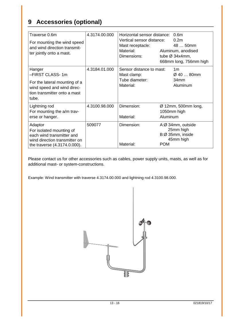
9 Accessories (optional)
Traverse 0.6m
For mounting the wind speed and wind direction transmit-ter jointly onto a mast.
4.3174.00.000 Horizontal sensor distance: 0.6m Vertical sensor distance: 0.2m Mast receptacle: 48 … 50mm Material: Aluminum, anodised Dimensions: tube Ø 34x4mm, 668mm long, 756mm high
Hanger –FIRST CLASS- 1m
For the lateral mounting of a wind speed and wind direc-tion transmitter onto a mast tube.
4.3184.01.000 Sensor distance to mast: 1m Mast clamp: Ø 40 … 80mm Tube diameter: 34mm Material: Aluminum
Lightning rod For mounting the a/m trav-erse or hanger.
4.3100.98.000 Dimension: Ø 12mm, 500mm long, 1050mm high Material: Aluminum
Adaptor For isolated mounting of each wind transmitter and wind direction transmitter on the traverse (4.3174.0.000).
509077 Dimension: A:Ø 34mm, outside 25mm high B:Ø 35mm, inside 45mm high Material: POM
Please contact us for other accessories such as cables, power supply units, masts, as well as for additional mast- or system-constructions.
Example: Wind transmitter with traverse 4.3174.00.000 and lightning rod 4.3100.98.000.

14 - 16 021819/10/17
10 EC-Declaration of Conformity
Document-No.: 001575 Month: 10 Year: 17 Manufacturer: A D O L F T H I E S G m b H & C o. K G
Hauptstr. 76 D-37083 Göttingen Tel.: (0551) 79001-0 Fax: (0551) 79001-65 email: [email protected]
This declaration of conformity is issued under the sole responsibility of the manufacturer Description of Product: Windsensor First Class Advanced II, Windsensor First Class Advanced X
Article No. 4.3352.00.000 4.3352.10.000 4.3352.00.400 4.3352.10.400 specified technical data in the document: 021813/10/17, 021818/10/17
The indicated products correspond to the essential requirement of the following European Directives and Regulations: 2014/30/EU DIRECTIVE 2014/30/EU OF THE EUROPEAN PARLIAMENT AND OF THE COUNCIL of 26 February 2014
on the harmonisation of the laws of the Member States relating to electromagnetic compatibility
2014/35/EU DIRECTIVE 2014/35/EU OF THE EUROPEAN PARLIAMENT AND OF THE COUNCIL of 26 February 2014 on the harmonisation of the laws of the Member States relating to the making available on the market of electrical equipment designed for use within certain voltage limits
552/2004/EC Regulation (EC) No 552/2004 of the European Parliament and the Council of 10 March 2004
on the interoperability of the European Air Traffic Management network (the interoperability Regulation) 2011/65/EU DIRECTIVE 2011/65/EU OF THE EUROPEAN PARLIAMENT AND OF THE COUNCIL
of 8 June 2011 on the restriction of the use of certain hazardous substances in electrical and electronic equipment
2012/19/EU DIRECTIVE 2012/19/EU OF THE EUROPEAN PARLIAMENT AND OF THE COUNCIL of 4 July 2012 on waste electrical and electronic equipment (WEEE) The indicated products comply with the regulations of the directives. This is proved by the compliance with the following standards:
EN 61000-6-2 Electromagnetic compatibility Immunity for industrial environment
EN 61000-6-3 Electromagnetic compatibility Emission standard for residential, commercial and light industrial environments
EN 61010-1 Safety requirements for electrical equipment for measurement, control, and laboratory use. Part 1: General requirements
EN 50581 Technical documentation for the assessment of electrical and electronic products with respect to the restriction
of hazardous substances
Place: Göttingen Date: 24.10.2017 Signed for and on behalf of:
This declaration certificates the compliance with the mentioned directives, however does not include any warranty of characteristics. Please pay attention to the security advises of the provided instructions for use.

15 - 16 021819/10/17

16 - 16 021819/10/17
ADOLF THIES GmbH & Co. KG Hauptstraße 76 37083 Göttingen Germany P.O. Box 3536 + 3541 37025 Göttingen Phone +49 551 79001-0 Fax +49 551 79001-65 www.thiesclima.com [email protected]
- Alterations reserved -