windenergy full web - giovenzana international b.v.€¦ · european standards usually originate...
TRANSCRIPT

GIOVENZANA
TECHNO-CONTROL EQUIPMENT
FGR3

The Company
GIOVENZANAINTERNATIONAL B.V.
Giovenzana’s philosophy is based upon the basic principlesof business management, dynamism and the continuousresearch for the operator’s needs in the field of man-machineinteraction. These principles, thanks to the experienceand professionalism of its staff, guarantees Giovenzana’sdevelopment and growth.
TECHNO-CONTROL EQUIPMENT
THE PHILOSOPHY
QUALITY AS A WAY OF LIFE
THE HISTORY
THE PRODUCTS
With over 50 years experience in this field and excellent managerial skills, Giovenzana has maintained growth relying upon:market researchproduct placementmanufacturing technology, and above all, team work
Giovenzana, leader in the industrial technology field, is the first choice for:handling equipmentautomationlifting equipmentmaintenancecommand and control of moving partsDevelopment, design and production are combined together to reach a common aim and cover most
The commercial success of a product is not by chance, but it is the end result of a combined effort of all human resources operating within an organisational structure devoted to quality. Giovenzana is an ISO 9001 certified company.

THE PRODUCTION
AUTOMATION
LIFT
LIFTING EQUIPMENT
The Company
GIOVENZANAINTERNATIONAL B.V.
The solutions offered by Giovenzana are the results of a close examination of the requirements of industrial electrical accessories, in line with all relevant international standards.It comprises three main sectors:Industrial automation, lift and lifting equipment.
It includes Phoenix cam switches and Regolus switch-disconnectors up to 100A, Pegasus control auxiliaries with screw or spring loaded terminal contact blocks; limit switches with die-cast or moulded casing and safety switches; foot switches and micro switches.
Throughout the years, the continuous technological research and development made Giovenzana the undisputed leader in this field. The range includes: pit bottom push button stations, recall drive control units and inspection boxes.
It comprises single and double row pendant stations up to 14 gang for control and direct switching power circuits, reversing switches, worm screw and rotary limit switches, slip rings, horns, festoon systems and conductor rails.

The Company
GIOVENZANAINTERNATIONAL B.V.
CERTIFICATIONS
QUALITY
COMPLIANCE
Giovenzana, leader in the elevator and lifting equipment fields, has gained a prominent position in the automation sector as well with the launch of industrial control accessories on the market. For many years now,all commercial and industrial operations are integrated within the frame of the UNI EN ISO 9001 quality system. CSQ certificate No. 9105Giovenzana has fulfilled its commitment to the quality of its products in 1995.The quality system is the guarantee to the end user that all production stages are maintained under strict control and adhere to the requirements set by the company bothin terms of customer expectations and compliance with the relevant international standards as proved by the various certificates held by Giovenzana for its products.
All Giovenzana products are manufactured accordingto the relevant Cee directives and are provided witha declaration of conformity which certifies their compliance.
For many years, Giovenzana has been submitting its products for third party testing to one of the most prestigious independent certification body around the world, the Underwriter Laboratories Inc. in order to obtain the UL mark. Today the number of independent certification bodies approving Giovenzana’s products is even bigger to signal the high level of quality achieved.

The Company
GIOVENZANAINTERNATIONAL B.V.
As from the 1st of January 1997, it is compulsoryto CE mark all electromechanical products: this hasbeen outlined by two important regulations: 72/23CEE and 93/68 CEE Low Voltage Directives.
STANDARDS
EN EUROPEAN STANDARDS
CEE DIRECTIVES
European directives, applied to all national regulations, set the minimum requirements in term of safety of all electrical material sold within the EU. The compliance to these requirements is certified to the manufacturer by the CE
Giovenzana’s products comply with both European EN and American UL standards. These regulations, such as the EN 60024 with regards to the safety requirements of the electrical circuits on board industrial machinery, define the characteristics and performance or the characteristics and use of the products.
These standards are the result of the harmonisation among CENELEC (European Committee for Electrotechnical Standardization) member countries. They cover and eliminate existing national standards which may be in contradiction or not up to date. EN European standards usually originate from IEC International standards.
CE MARK

FGR3 - Rotary gear limit switch
GIOVENZANAINTERNATIONAL B.V.
TECHNO-CONTROL EQUIPMENT
GIOVENZANA INTERNATIONAL has developed, during this year, the Rotary gear limit switches to equip the wind energy turbines, with a main characteristic of flexibility to adapt our product to a big range of customization by clients.
We began to research in this field to manufacture a product deleting the defects of the principal competitors, the actual owner of the limit switches range in the market.Our engineering studies, shoot for supply an high quality standard product in terms of reliability and availability of the equipment. Using advanced technological approaches (i.e. materials, simulation techniques, …), we aim a developing a product that could become, in short time, a reference system in the market nowadays. The project has been developed to warrant, in the same time, the correct functionalities of the rotary switch and overall the resistance to the high critical working conditions (determined by temperature, humidity and position to hook up the box in its seat), and very high precision to control and regulate the rotation of the nacelle.
We have had a lot of experience and competence in the limit switch products; as a consequence, with the introduction of this innovative product in the market, we have overcome the problems related to this kind of equipment and we are able to warrant the best performances during a long life-time. All above characteristics are not only a paper declaration, but will be shown thanks to the several tests which have the purpose to stress the product in its “real” working conditions. Finally, we are sure to achieve the leadership using the best equipment components and looking for the high quality plastic materials.
PROJECT FOCUS AND MARKET AREA
Picture 2.: Product destination
Picture 1.:Complete product rendering and position

Rotary gear limit switch for wind turbinesFGR3
TECHNO-CONTROL EQUIPMENT
The new code of our product will be a “speaking code”, in which each single number means a specific functionality. The code provides all the information which can be used for defining the different customization which we’ll be able to supply to our customers. In fact, one of the main characteristics of the equipment here shown is its flexibility, as it is possible to state by following examples:
For example, our first prototype which we’ve manufactured had the following code: FGR310604161 that means the following product description: Rotary gear limit switch for wind turbines, with encoder, gear ratio cams group 1:60, with n.4 microswitches, equipped by single shaft with 50mm length outside from plastic box and mounted a pinion size as Giovenzana code 16020061.
GIOVENZANA’S CODE AND DETAILED DESCRIPTION
NO, no optical
readerequipped
with screw’s holes to a future
equipment.
YES, encoder
completedby its
supportand brass
driver.
YES, potentio-meter
completed by its
support and brass
driver.
N. ratio gearmin 001 tomax 999
Number of microswitch
and correspondent
cams.We have
two differentconfigurations:
2 camsor 4 cams.
Singleoutputof theshaft
Doubleoutput ofthe shaft
Two last numbers of the code
correspondent of thepinion size (like
M14Z10 have “61” from 16020061).
In the casewithout any pinion will
be 00
0 1 2 2/4 1 2
Ratio GearNo
OpticalReader
Encoder Potentio-meter Shaft Pinion typeNr. of
microswitch
Picture 3.: Rendering of FGR3 inner view the plastic box
Rotary gear limit switch for wind turbinesFGR3
TECHNO-CONTROL EQUIPMENT
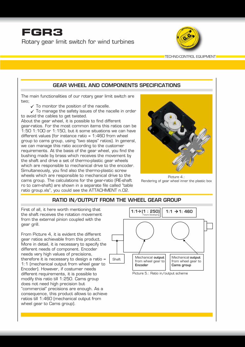
The main functionalities of our rotary gear limit switch are two; To monitor the position of the nacelle. To manage the safety issues of the nacelle in order to avoid the cables to get twisted.About the gear wheel, it is possible to find different gear-ratios. For the most common items this ratios can be 1:50 1:100 or 1:150, but it some situations we can have different values (for instance ratio = 1:460 from wheel group to cams group, using “two steps” ratios). In general, we can manage this ratio according to the customer requirements. At the basis of the gear wheel, you find the bushing made by brass which receives the movement by the shaft and drive a set of thermo-plastic gear wheels which are responsible to mechanical drive to the encoder. Simultaneously, you find also the thermo-plastic screw wheels which are responsible to mechanical drive to the cams group. The calculations for the gear-ratio (RE-shaft ro to cam-shaft) are shown in a separate file called “table ratio group.xls”, you could see the ATTACHMENT n.02.
First of all, it here worth mentioning that the shaft receives the rotation movement from the external pinion coupled with the gear grill.
From Picture 4, it is evident the different gear ratios achievable from this product. More in detail, it is necessary to specify the different needs of component. Encoder needs very high values of precisions, therefore it is necessary to design a ratio = 1:1 (mechanical output from wheel gear to Encoder). However, if costumer needs different requirements, it is possible to modify this ratio till 1:250. Cams group does not need high precision but “commercial” precisions are enough. As a consequence, this product allows to achieve ratios till 1:460 (mechanical output from wheel gear to Cams group).
GEAR WHEEL AND COMPONENTS SPECIFICATIONS
RATIO IN/OUTPUT FROM THE WHEEL GEAR GROUP
Picture 4.:Rendering of gear wheel inner the plastic box
Picture 5.: Ratio in/output scheme
Mechanical outputfrom wheel gear to Encoder
Mechanical outputfrom wheel gear to Cams group
Shaft
1:1 (1 : 250) Future Developing
1:1 1: 460

The encoder, which is the most important component of our product, aims at providing the precise position corresponding to max wind-power direction, overall gives a signal to measure the exact position of the nacelle which is done by the average of this incremental encoder built in our limit switch. The encoder allows to define the accurate position of the nacelle with a resolution of ± 1°. From common knowledge, the possibility to move the nacelle in the suitable direction should improve machine energy performance about 27%. The optical encoder is connected to the stack of four cams in order to establish the rotation angle. The resolution of encoder is determined by the pulse/Rpm, which depends of the sort of encoder required.For Technical Data Sheet of the incremental encoder, please see the ATTACHED 02
Overall dimensions120X160X145h mm (obviously without pinion) with a weight about 1,5 KgFixingThe product fixing has been developed by four holes to clamp a metal flange. This choice is due to the flexibility of the product since it can be changeable with the products developed by competitors.We refer to the holes distances of the flanges fixed under the plastic box and overall dimensions.Cables of the product The product is equipped by N.3 cable exit with the cable-glande M20.WaterproofThe limit switch is tested for IP66. This property is warranted by a rubber gasket of all perimeter on the coupling plane between the plastic black box and yellow cover and two “corteco” caps mounted on the side shaft holes. This product is frost smoke - resistant.Mechanical stressMax Rpm : 50rpmMax radial force: 14NThe shaft is mounted with ball bushing
Rotary gear limit switch for wind turbinesFGR3
TECHNO-CONTROL EQUIPMENT
PCB BOARDS AND ELECTRICAL COMPONENTS SPECIFICATIONS
MECHANICAL CHARACTERISTICS
Picture 6.:Rendering of the PCB boar and mini
incremental encoder

Omologation: CE, UL/CSA (US market), on request CCC, Ghost and RINA).
Giovenzana rotary gear limit switch for wind turbines will be applied the most updating laws like:- Standard 2006/95/CE (Low tension)- Standard 98/37/CE with reference to 2006/42/CE (Machinery Directive)- Standard 89/336/CE with reference to 2004/108/CE (Directive electromagnetic compatibility)
The following list the standards which you use to calculate the “failure rate” (FIT) of the components.
IEC 60319, Presentation of reliability data on electronic components or partsIEC 60300-3-2, Dependability management Part 3-2: data collectionIEC 60300-3-5, Reliability test conditions and statistical test principlesIEC 60050-191, International Electrotechnical Vocabulary (IEV) - Part 191; Dependability and Quality of serviceIEC 60721-1, Classification of environmental conditions - Part 1: Environmental parameters and their severitiesIEC 60706-3, Verification and collection analysis and presentation of dataIEC-62380-TR, - Reliability Data Handbook - Universal model for reliability prediction of electronics components, PCBs and equipment.
Known the FIT of each components we can calculate the MTBF following:IEC 61709 Electronic components - Reliability - Reference conditions for failure rates and stress models for ConverCEI EN 61124 (CEI 56-34): Reliability tests.
Further reliability lawsIEC 60605-6, Equipment reliability testing - Part 6: Tests for the validity and estimation of the constant failure rate andconstant failure intensityEN 60812 (CEI 56-1) – Analysis method for system reliability. Analysis Failure Mode & Effects Analysis (FMEA)CEI EN 61124 - CEI 56-34 – Reliability tests
Preliminary certification tests following the standards:EN 61000-6-2 +EC + IS1EN 61000-6-3EN 60204-1 + A1EN 60529 + A1EN 62262EN 60068-2-1EN 60068-2-2EN 60068-2-14EN 60068-2-30EN 60068-2-78CISPR 16-2-3EN 61000-3-2EN 61000-3-3CISPR 16-2-1(CA), CISPR 16-1-2(CA), CISPR 16-14-1(CA), CISPR 16-2-1(DC), CISPR 16-1-2(DC)CISPR 22
EN 61000-4-8, EN 61000-4-3, EN 61000-4-2, EN 61000-4-6, EN 61000-4-4, EN 61000-4-5;EN 61000-4-6, EN 61000-4-4, EN 61000-4-5 (CC and AC), EN 61000-4-11.
Rotary gear limit switch for wind turbinesFGR3
TECHNO-CONTROL EQUIPMENT
QUALITY DECLARATION STANDARDS AND PRODUCT’S OMOLOGATIONS

Rotary gear limit switch for wind turbinesFGR3
TECHNO-CONTROL EQUIPMENT
TECHNICAL DATA SHEET
Option of the FGR3 SpecificationsWeight Less than 1,5kgHousing material Thermo plastic materialShaft stainless steel shaft, 12mm diameter (AISI 304 INOX)Ball bushingPinion gear Options with different pinions n. 16 different size, from M6 to M22Gear ratio Options for modular pinion gearwheels, range from 1:1 to 1:460
Power supply range 5-30VDCIndipendent mechanical output 2 outputMax radial load 14NStart torque <0.01NmMax Rpm 900 RpmProtection class IP66 acc.EN60529EMC / Transient protection certified according with EN50081-1/EN50082-2Vibrations (10-2000Hz)/10GBump 10G-16ms (1000x3 Axis)Enviromental temp. working From -40°C to +90°CEnviromental temp. stockage From -40°C to +90°CFixing product Options equipped by different coupling flange
Product certification CE and UL, as per request we can supply certification CCC and CSA
Mini shaft encoder incorporated in switchDurable electronic terminal boardPossible direct connection to PLC
Internal helical gear Thermo plastic material auto-lubrificated to cams group and brass helical to encoder
SKETCH OF THE MECHANICAL DIMENSION:
FGR3 has been producted with 3 output to be equipped by cable-glande M20.
The inner wires connection can be supplied with flange mounting connection follow the scheme in the table:
Connection / Terminals
CAM2 CAM1 Shield Reset A sig. Bsig. 24V Ground CAM4 CAM3 CAM5 CAM6
Terminal output for inductive sensor Shield Ground 24V Reset

Rotary gear limit switch for wind turbinesFGR3
TECHNO-CONTROL EQUIPMENT
MAIN SPECIFICATIONS OF MINI-ENCODER
Output waveform Incremental A, B, Z and invertedZero or index pulse (Z) one pr./rev.Supply voltage Min 4.5V to max 30V Reverse polarity protectionCurrent (no load) 35 mAMax load per output 20 mAV out low Max 500mV at current out low I=10mAOperation Temperature -40°C a +85°CStorage Temperature -40°C a +85°CMax pulse frequency 200KHz
Cable Data 5(0.14mm2)or 8-leads(0.005mm2)shieldedMax Rpm (Max freq/pulses pr rev. )*60Phase diff. 90° ± 20%Duty cycle 50° ± 10%Cable 5x0, 14mm2 shieldedOutput signal Standard, Inverted or differentialCertified acc.to EN50081-1 e EN50082-2
Weight appx. 12gContacts Positive opening contacts according with EN60947-5-1Contact material Golden contactRelease force Min. 0.4NActuating force Max. 2.25NIth 6A
Operating temperature -40°C to + 85°C
N. of micro/cams Std. from 4 to 6
Terminal leads Blade terminals quickconnect 6.3mm x 1 or 6.3mm x 2.5 DIN 46247
Protection class IP40 IP00(terminals) according with EN60529
V out high Min(Vin -0.6)@ I=-10mA Min(Vin -1.3)@ I=-25mA
CONNECTING WIRE FOR ENCODER
MAIN SPECIFICATIONS OF MICROSWITCH
More details you could see in the Att.05
More details you could see in the Att.05
Colour wire functionWhite 1 Ground.Brown 2 24VYellow 3 BGreen 4 AShield 5 Shield