window cleaning robot - university of toronto · 2 abstract the objective of this project was to...
TRANSCRIPT

Window Cleaning RobotASME Design Competition
Author: Supervisor:Ori Barbut W.L. Cleghorn
A thesis submitted in conformity with the requirementsfor the degree of Bachelors of Applied Science
Department of Mechanical and Industrial EngineeringUniversity of Toronto
Copyright c© 2008
2
Abstract
The objective of this project was to design and construct a robot, to clean a double-hung
sash window as fast as possible.
This robot was constructed to compete in the 2008 American Society of Mechanical
Engineers (ASME) Student Design Competition. It is a proof-of-concept style competi-
tion, so to demonstrate the potential of such a cleaning robot, it must clean off a series
of dots from the window, applied with a dry-erase (ie, whiteboard) marker.
This project required the development of creative solutions to several problems, in-
cluding designing a robot that can translate on a vertical surface, making the device
capable of repeatably moving between window panes (separated by a change in height
as well as a change in depth, due to the nature of a double hung sash window), and
translating over the entire window area as efficiently as possible.
Although the contest rules allow for an autonomous or a tethered robot, this project
has resulted in an autonomous entry to the competition, which will be held on the
weekend of April 4th to April 6th, 2008, at Carnegie Mellon University.

3
Acknowledgements
There are several organizations and people I would like to acknowledge and thank the
following for donations in kind, support, answers to questions, and discounts for my
out-of-pocket budget.
First and foremost, I would like to thank my parents. Not only did they provide me
with an education and endless encouragement, they also provided “financial contribu-
tions” towards the completion of this project.
Kurt Farnsworth and the rest of the kind people at Marvin Windows and Doors of
Canada for their donation of a WUDH2020 double-hung sash window. This competition-
spec window has allowed me to test my designs in preparation for the competition in
April.
Brian Morton, Jackie James, and the rest of the people at Metaplast Circuit Ltd for
making my circuit boards for free.
David Brunning, Gary Campbell, and the people of Nova Product Development Ser-
vices, for the use of their FDM machine to manufacture plastic parts for me.
The people of Comair Rotron Inc and the people of NMB Technologies Corporation
were both helpful in answering my questions about their centrifugal fan products.
Last but not least, I would like to thank my friends and family for their constant
encouragement in this project. Even when things looked grim, they knew I would finish
this robot.

Contents
1 Introduction 6
1.1 Background . . . . . . . . . . . . . . . . . . . . . . . . . . . . . . . . . . 6
1.2 Design Changes . . . . . . . . . . . . . . . . . . . . . . . . . . . . . . . . 7
1.2.1 Window Attachment . . . . . . . . . . . . . . . . . . . . . . . . . 8
1.2.2 Climbing Between Windows . . . . . . . . . . . . . . . . . . . . . 8
1.2.3 Electronics . . . . . . . . . . . . . . . . . . . . . . . . . . . . . . . 9
2 Mechanics 10
2.1 Cleaning Pad . . . . . . . . . . . . . . . . . . . . . . . . . . . . . . . . . 11
2.2 Centrifugal Blower . . . . . . . . . . . . . . . . . . . . . . . . . . . . . . 11
2.3 Drivetrain . . . . . . . . . . . . . . . . . . . . . . . . . . . . . . . . . . . 12
2.4 Winch . . . . . . . . . . . . . . . . . . . . . . . . . . . . . . . . . . . . . 12
2.5 Lift Servos . . . . . . . . . . . . . . . . . . . . . . . . . . . . . . . . . . . 13
3 Electronics 14
3.1 Power Supply . . . . . . . . . . . . . . . . . . . . . . . . . . . . . . . . . 14
3.2 DC Motors . . . . . . . . . . . . . . . . . . . . . . . . . . . . . . . . . . 14
3.3 Servo Motors . . . . . . . . . . . . . . . . . . . . . . . . . . . . . . . . . 15
3.4 Optical Encoders . . . . . . . . . . . . . . . . . . . . . . . . . . . . . . . 15
3.5 Inter-microcontroller Communications . . . . . . . . . . . . . . . . . . . 15
3.6 Printed Circuit Board . . . . . . . . . . . . . . . . . . . . . . . . . . . . 16
4
CONTENTS 5
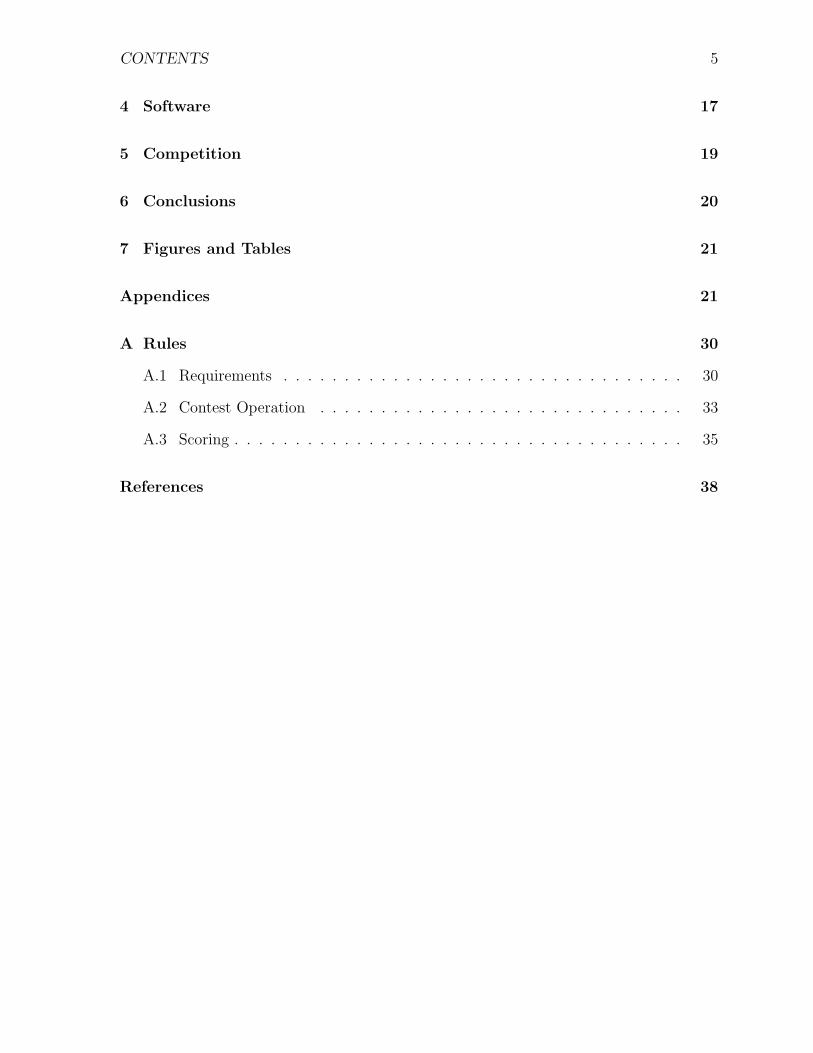
4 Software 17
5 Competition 19
6 Conclusions 20
7 Figures and Tables 21
Appendices 21
A Rules 30
A.1 Requirements . . . . . . . . . . . . . . . . . . . . . . . . . . . . . . . . . 30
A.2 Contest Operation . . . . . . . . . . . . . . . . . . . . . . . . . . . . . . 33
A.3 Scoring . . . . . . . . . . . . . . . . . . . . . . . . . . . . . . . . . . . . . 35
References 38

Chapter 1
Introduction
1.1 Background
The restrictions in the ASME Design Specifications[1] require the robot to be smaller
than a single pane of the window. As a result, this project fundamentally demands a
solution to the problem of translation on a vertical surface. Formal projects in this area
can be categorized into three groups: legged robots with suction at feet (using either
active[3] or passive[2] suction), legged robots with clawed feet to grip a surface (This is
seen in combination with secondary feet that use suction on the RiSE series of robots[5]),
or wheeled robots with air evacuated between the robot and the surface[6].
To decide between these methods, I evaluated each based on the factors of speed,
complexity of design, and stability in switching between window panes. The clawed foot
approach was clearly out of the running, as it would not apply for this surface - claws have
been shown effective on surfaces such as brick, but would not work on a glass window.
Both to be considered, as a result, are devices that use suction, and were evaluated on a
high-medium-low scale.
6
Chapter 1. Introduction 7
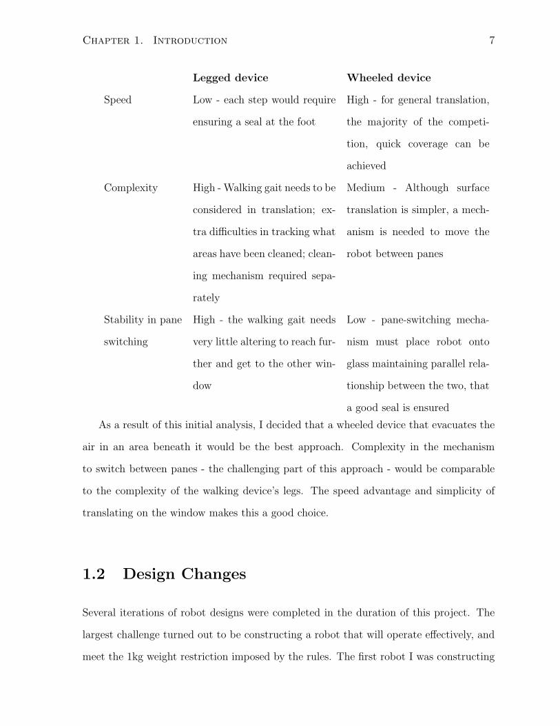
Legged device Wheeled device
Speed Low - each step would require
ensuring a seal at the foot
High - for general translation,
the majority of the competi-
tion, quick coverage can be
achieved
Complexity High - Walking gait needs to be
considered in translation; ex-
tra difficulties in tracking what
areas have been cleaned; clean-
ing mechanism required sepa-
rately
Medium - Although surface
translation is simpler, a mech-
anism is needed to move the
robot between panes
Stability in pane
switching
High - the walking gait needs
very little altering to reach fur-
ther and get to the other win-
dow
Low - pane-switching mecha-
nism must place robot onto
glass maintaining parallel rela-
tionship between the two, that
a good seal is ensured
As a result of this initial analysis, I decided that a wheeled device that evacuates the
air in an area beneath it would be the best approach. Complexity in the mechanism
to switch between panes - the challenging part of this approach - would be comparable
to the complexity of the walking device’s legs. The speed advantage and simplicity of
translating on the window makes this a good choice.
1.2 Design Changes
Several iterations of robot designs were completed in the duration of this project. The
largest challenge turned out to be constructing a robot that will operate effectively, and
meet the 1kg weight restriction imposed by the rules. The first robot I was constructing

Chapter 1. Introduction 8
turned out to be over this weight limit; and there is no point deduction as a weight
penalty within the rules, a disqualification occurs.
This meant going back to the drawing board with respect to this project; but it was
with several lessons learned. In this section, the major changes are described.
1.2.1 Window Attachment
The first design used a windshield washer fluid pump to generate a negative pressure.
Although this worked for a while, it would require a cooldown period, as this pump was
not designed to “run dry.” This lesson was learned after a pump needed to be replaced
after being run for too long, which resulted in membrane wear.
The solution to this problem was to use a centrifugal blower. This was not only
designed to run pneumatically, but it also provides a greater pressure difference, and a
high airflow rate. The increased air flow rate resulted in faster adhesion time (essen-
tially instantaneous when the robot is placed on the window). The centrifugal blower is
discussed in more detail in Section 2.2 on page 11.
1.2.2 Climbing Between Windows
The operation to switch between windows is an extremely difficult maneuver, and has
also been the prime source of complaints among the various entrants to this competition.
At the ASME Leadership Training Conference in Atlanta, the student representatives in
attendance discussed the challenges and agreed that because of this, this competition is
significantly more difficult than past years.
My initial design was to have a robotic arm, with a full range of motion, that would
extend to the top window and adhere to it with a suction cup. The complexity in joint
control so that the robot could work with multiple window dimensions was a weak point
of this design.
I optimized this by using a set of parallelogram 4-bar linkages, in a design that was

Chapter 1. Introduction 9
constructed. The weight of this arm and the extra pump required was what pushed the
robot over the 1kg limit.
I consulted the database of questions asked to the ASME competition organizers, and
saw that several students asked about pulling on the safety tether that must be attached
to the robot anyway. This was ruled to be an allowable method of translation; and quickly
became the method I would pursue. Not only was there a reduction in the number of
motors needed (one to pull on the cable, instead of the three previously included in the
parallelogram arm design). This put my robot within the weight requirements, and the
mechanism is described in detail in Section 2.4 on page 12.
1.2.3 Electronics
The changes in electronics as a result of my hardware changes were not very substantial.
Although a new circuit board was required to account for different connections made, the
majority of the aspects remained the same. The wheel encoder system was unchanged; it
was simply scaled up to keep track of how much the winch system had wound the safety
tether. The motor driving circuitry was largely unchanged, the only big difference is the
new use of servo motors to raise the robot over the window ledge. This just required a
pulse-width-modulation control on an unused set of timers within the microcontroller,
and was not much trouble to account for.

Chapter 2
Mechanics
As discussed in Section 1.2 on page 7, there were several design changes made part way
through the school year in order to account for the restrictive 1kg weight limit. This
section will discuss the final design of the robot; the previous design was outlined in the
Thesis Progress Report.
The majority of the chassis of the robot is made from plastics. The frame is ABS,
manufactured by a Fused Deposition Modelling (FDM) machine. The bottom sheet is
machined from a 0.25 in. PTFE (Teflon R©) sheet, to provide an effective seal with little
added friction.
The wheels have soft urethane tires, which provide the frictional force that keeps the
robot in place, proportional to the normal force provided by the centrifugal blower. The
circuit board and batteries are both mounted at the top of the robot, the batteries with
Velcro and the circuit board with standoffs.
Microswitches are used to detect the edges of the window frame.
A rendering is provided in Figure 7.1 on page 22, which consists of the SolidWorks
models used to make the frame of the robot (with the FDM machine) and the base of
the robot (CNC machined from sheet-stock PTFE), as well as the other components of
the robot.
10

Chapter 2. Mechanics 11
2.1 Cleaning Pad
The cleaning pad removes the dry-erase marker dots from the window as it passes over
the glass. Since no liquids are allowed by the competition rules, I tried out a few types
of microfibre cloth in order to clean the dry-erase marker. I selected a Microtex Cleaning
Towel from Canadian Tire as the best cloth for dry-erase markers. Microfibre cloth works
on the principle of molecular attraction, and essentially uses static electricity to lift the
dust left behind by a whiteboard marker. To allow for quick changes between cleaning
pads (in order to use a clean pad at the start of a trial), this is mounted with the hook
component of hook-and-loop tape, on the Teflon sheet at the front of the robot. The
hook portion of this Industrial Grade Velcro from Canadian Tire was able to mount the
microfibre cloth directly, with no loop component used.
2.2 Centrifugal Blower
The first centrifugal blower I purchased was a Comair Rotron model WT12B3QDN. This
provided a pressure difference of under 1 inch W.C. which is high for a blower of this
size, but did not seem to be quite enough pull.
I tried to obtain a AMD12K3E from Comair Rotron, which can maintain a static
pressure of 1.7 inches W.C., but due to manufacturing supply line problems, the lead
time was pushed back until midway through May; and none were available off-the-shelf
at any distributor.
Fortunately, I came across a small stockpile of high-pressure centrifugal blowers from
NMB Technologies. I selected the high-speed version of the BG0903 fan, which is the
-047 designation, due to it’s fan curve, as shown in Figure 7.2 on page 23
From this graph, one can see that in a dead-head condition of no airflow, a static
pressure of 1.9 inches W.C. will be achieved. This is more than enough for the purpose
of driving the robot on a vertical surface. The suction of the fan causes the wheels to

Chapter 2. Mechanics 12
compress slightly, and this is the source of the frictional force parallel to the glass pane.
The blower can be seen in detail, along with the filleted opening that channels the
fan inlet from the PTFE sheet, in Figure 7.4 on page 24.
2.3 Drivetrain
The robot’s drivetrain consists of a pair of GM8 motors from Solarbotics, with injection-
molded wheels designed for the output shaft on those motors. They have an added
urethane tire in place, with 14 durometer Shore A specification. These soft tires maximize
the friction with the glass. Two motors instead of four allows for a no-skid assumption
in calculating the position of the robot - turning on just one wheel for a turn essentially
results in a pivot about the other wheel. This consistently maneuvers as anticipated.
There are optical encoders which observe wheel motion based on a striped pattern on
the wheel. These encoders are an off-the-shelf product from Solarbotics, and are further
described in Section 3.4 on page 15.
2.4 Winch
The robot lifts itself between window panes using the safety tether (12 lb test fishing
line), and specifically winding this up with the winch mechanism.
The winch consists of a gearmotor (A GM3 from Solarbotics, which is similar to the
GM8 used for the wheels, except with a greater maximum torque), an optical encoder
(the same kind as those on the wheels), and a custom-made winding pulley. This was
manufactured using FDM out of ABS, and is dimensioned such that one revolution
translates to 15cm of tether released or pulled in.
The winch motor is set up to electronically brake with no power applied if the batteries
are running low (by shorting the motor terminals). It has a stall torque of 5 oz·in when
operated at 5V, but this robot can operate the motor at greater voltages as needed.
Chapter 2. Mechanics 13
2.5 Lift Servos
A pair of standard Hobbico R/C hobby servos are used to lift the robot from the window
surface while climbing up to the top window pane.
Since the robot needs to get over a ledge, these motors provide “stilts” that support
the robot while it is pulling on the safety cord. This only occurs once the safety line is
taught (indicated by the reduction in encoder pulse speed from the winch motor), since
it would otherwise cause the robot to fall.
These servos have their position controlled by a series of pulses as described in the
Electronics chapter, Chapter 3 on the next page.

Chapter 3
Electronics
The circuit used in my design is shown in Figure 7.5 on page 25 to 7.8 on page 28.
This uses two AVR ATMega64 processors, each with 64 kB of program memory, and
several hardware functions.
3.1 Power Supply
The power supply consists of a lithium polymer battery pack, with 4 cells. Each cell has
a capacity of 1100 mAh, and a voltage of 3.7V.
This is charged by an external charger. A resistor network provides a fraction of
the total voltage for monitoring purposes, on a scale that works within the range of the
Analog input pins of the microcontrollers. This allows the robot to enter an emergency
low-battery mode, where the latching relay across the winch motor is activated, shorting
it’s terminals, and electronically stopping the motor.
3.2 DC Motors
The DC motors are controlled with pulse-width modulation, to allow a full range of speed
control. They use the feedback from the optical encoders to determine the number of
14
Chapter 3. Electronics 15
revolutions made, and the speed of said revolutions.
3.3 Servo Motors
The servo motors are controlled with pulse width modulation as a data carrier. A 50%
duty cycle places the servo motors in the centred position, and varying this will change
the position proportionally in a 270-degree range.
3.4 Optical Encoders
The optical encoders were purchased from Solarbotics, and they provide quadrature data
to the robot, as well as decoded quadrature output. The pulses are counted by using
hardware timers of the AVR microcontrollers, as seen in the schematics. This means that
no processor time is used to keep track of how far the robot has travelled, reducing the
program complexity.
The principle of operation is a pair of reflective infrared sensors, counting the stripe
patterns that are integral to the wheels.
3.5 Inter-microcontroller Communications
The microcontrollers interact using the Two-Wire Interface (TWI) standard, also known
as I2C (Integrated Circuit to Integrated Circuit). This data bus is shown with the
required pull-up resistors in the schematic.
All communications details are handled in hardware, again reducing the software
complexity.

Chapter 3. Electronics 16
3.6 Printed Circuit Board
The full layout of the printed circuit board is shown in Figure 7.9 on page 29. As you
can see, this is a very densely populated surface-mount board design, done so to reduce
weight as much as possible.

Chapter 4
Software
The software of the robot is fairly straightforward, and is the only part that is still being
fine-tuned before the competition.
The code is written in C, compiled by the GNU Compiler Collection for the target
AVR microcontrollers. The operational principle is to have the robot drive along the
perimeter of the bottom window, then fill in missing area (having measured the window
by means of wheel turns). The robot then lifts itself to the top window pane, and cleans
it with the same pattern. It lowers itself down using the tether again, and waits at the
starting point to be picked up by the operator.
It is important to maintain a straight heading using the accelerometer data (which
essentially indicates the direction of gravity) and the encoder data (which indicates wheel
speeds, which must be matched between the robots). This part of the system control is
done on the motor control AVR, and is the bare-bones “low-level” functionality of the
robot.
A second AVR microcontroller handles the high-level control of the robot. While the
first controller can be thought of as the nervous network, the second is the brain. It
provides instructions for the task-oriented first controller, and also controls the lifting
arm servos, the winch motor, and the centrifugal blower.
17

Chapter 4. Software 18
As described in the Electronics chapter, Chapter 3 on page 14, a majority of inter-
facing tasks are handled in hardware on the AVR microcontrollers, which keeps the code
of the robot simple.

Chapter 5
Competition
Through both the question-and-answer website of this ASME competition, and the re-
action of the school delegates at the recent ASME Leadership Training Conference, it is
clear that the consensus is that this year’s competition is significantly more challenging
than those in the past. In working on this group project by myself, I am at a disadvantage;
but this may still turn out to work very well.
Twishansh Mehta, the Vice-Chair of the ASME University of Toronto Student Sec-
tion, spoke to other competitors at the Leadership Training Conference. The lack of
functionality of many of my competitors means that I potentially have a better robot
than the other submissions.
If my robot performs well at the upcoming competition at Carnegie Mellon University,
I will compete this design in Boston, in November 2008. Between now and then I can
further improve the transition between windows while climbing down, as currently there
is heavy reliance on the tether.
Between now and the competition on April 4th, I am going to be doing some more
fine-tuning of the robot software.
19

Chapter 6
Conclusions
This project was a major learning experience. I benefitted greatly by an early start, as
unforeseen problems were caught in time for a complete redesign of my robot.
My software, mechanical, and electrical design abilities were put to the most rigorous
test I’ve experienced in my undergraduate career, which was very enjoyable. My prime
regret is not persuing this with a group, as my supervisor Professor Cleghorn initially
suggested. It puts me in the unique situation of being the smallest team entered in the
ASME competition - only one member! For a comparison, there are two teams of three
students, and four teams of four student also registered to compete in this divisional
competition.
It was a lot of work, but several hundred hours (and several hundred dollars) af-
ter starting this, I am happy that I have a good chance at placing in the competition
standings in April.
Overall, this project was successful in the construction of a window cleaning robot,
and I look forward to finishing up the fine-tuning and competing my design.
20

Chapter 7
Figures and Tables
21

Chapter 7. Figures and Tables 22
Figure 7.1: Isometric perspective of final robot design, rendered in SolidWorks

Chapter 7. Figures and Tables 23
Figure 7.2: Fan curve for BG0903-047 centrifugal blower[4]

Chapter 7. Figures and Tables 24
Figure 7.3: A view of the rear and underside of the robot, which illustrates the outletand inlet of the centrifugal blower
Figure 7.4: The robot as it lifts itself from the glass surface, using the servo motors atthe sides (red servo horns are displayed)

Chapter 7. Figures and Tables 25
Figure 7.5: The schematic of the motor controller AVR, and associated electronics

Chapter 7. Figures and Tables 26
Figure 7.6: The schematic of the high-level controller, and associated electronics

Chapter 7. Figures and Tables 27
Figure 7.7: The schematic of the high-current output circuits used in the robot design

Chapter 7. Figures and Tables 28
Figure 7.8: The schematic of the power distribution and programming connection to thepair of microcontrollers

Chapter 7. Figures and Tables 29
Figure 7.9: The circuit board layout of the robot’s electronics

Appendix A
Rules
The rules from the ASME Student Design Competition, which this device will be con-
strained by, follow verbatim[1] in this Appendix:
A.1 Requirements
1. Once placed on the window glass and turned on Winrobo must maintain itself on
the specified vertical residential window and move around as necessary on the sur-
face without assistance. Winrobo may touch or make use of the wood, vinyl, or
aluminum surface surrounding the glass if desired, but may touch only those sur-
faces within 25 mm of any part of the (clear) window pane being cleaned. Winrobo
may not touch the outside or the inside of the building wall or the trim area around
the window (either inside or outside).
2. If operating autonomously, Winrobo must find the edges of the window on its own
and complete its cleaning processit may not be pre-programmed to only clean the
one size window specified for this contest.
3. If operating under remote ope window pane will be clear of obstacles such as mul-
lions (which break the window pane into a number of smaller panes when used.)
30

Appendix A. Rules 31
A simple-to-construct window of nearly the same construction dimensions is given
in the drawings given as part of this contest definerator control, the following rules
apply:
(a) The controller and the robot must be connected by an umbilical cord which
carries only control signals. The control box may not include any batteries or
auxiliary power. Radio control is not permitted.
(b) The umbilical cord must be connected to the robot through a commercially-
available 9 or 15 pin sub-D connector
(c) The umbilical cord cannot be more than 2 mm in its thinnest dimension so
that it can pass through a crack above or below a closed window.
(d) The umbilical cord must be able to withstand repeated clampings between the
moving and stationary parts of the window without damage.
4. Winrobo must be provided with a safety cord which can be closed into the window
frame or otherwise secured in a non-marring way to the building wall, and which
will prevent Winrobo from falling more than two feet below the elevation of the
middle of the lower window pane in the event of a malfunction. If an umbilical cord
is used it may NOT also be used as the safety cord.
5. While on the window Winrobo must clean the window by wiping off the dry erase
ink used to simulate dirt on the window.
6. Winrobo must carry within itself 50 ml of water, which will simulate the cleaning
fluid which would be used in the final design. This water must not leak out or be
pumped out of the device during testing. It will not be used in actual cleaning.
7. Winrobo must be capable of cleaning the entire window pane on which it is mounted.
It may not leave some areas which it cannot clean (such as under attachment points
Appendix A. Rules 32
on the window pane if, for example, immovable suction cups were used to hold Win-
robo to the window).
8. Winrobo should be capable of moving from pane to pane on the window on its own
or under operator control from inside the “building”. A major scoring bonus will
be awarded for successfully completing the transition from lower to upper window
pane.
9. Winrobo must be battery powered. The maximum battery voltage allowed is 24
Vdc maximum. The battery must be rechargeable. Winrobo must be capable of
cleaning the outside of the test window without needing to be recharged.
10. Winrobo must have a safety system on it so that if the battery voltage drops below
a “safe” level it will go into a “safe” mode where it stops cleaning and simply clings
to the window pane while turning on a warning light. Team members must be able
to describe this system to the judges as part of the qualification inspection.
11. When Winrobo is finished with a window it must turn off all cleaning operations,
go the lower left-hand corner of the lower pane as viewed from the outside of the
“building”, and turn on a signal light to indicate finished status.
12. The maximum allowable time for Winrobo to clean a window (both panes on the
outside of the window) is 5 minutes.
13. Winrobo must be capable of being packed, fully assembled and ready to operate,
inside a box with the inside dimensions of 600mm x 800mm × 300mm high. The
300mm dimension is the horizontal distance between the window pane and a vertical
plane tangent to the point of Winrobo which is farthest from the window when
Winrobo is in the operating position.
14. Winrobo must not weigh more than 1 kg when fully charged with fluids.

Appendix A. Rules 33
15. Winrobo may not damage the window or window frame in any way.
A.2 Contest Operation
1. At each contest one residential window will be provided. This may be a window
built to the specifications of this contest, or may be a commercially available one.
The exact type and size of the window is up to contest organizers, so long as the
size of the visually clear panes fall within the range of 50 to 53 cm in width and
height.
2. The judging team will mark off the inside of the test window with a regular grid
of lines spaced approximately 105 mm apart and as nearly square as practical.
Only integral numbers of rows and columns should be used. For the recommended
windows a grid of 5 rows and 5 columns is suggested.
3. Immediately following check-in and sizing inspection all teams will have about one-
half hour to prepare and test their devices. Test windows or window panes will not
be provided by the organizers, and testing may not be done on the actual contest
window. Teams should be prepared to test their devices as necessary during this
time.
4. Once all teams have assembled and prepared their devices all teams will participate
in a peer review session. During that time team members are expected to review
all of the competing devices and to review them for any potential rules violations.
If a team member suspects a device does not meet contest specifications he or she
should report the problem to one of the contest judges. At the conclusion of the
peer review session the judges will resolve any questions and conflicts. After the
close of the peer review session no more questions will be accepted by the judging
team from any team member about another teams device or its operation.

Appendix A. Rules 34
5. During the peer review session the judging team may also conduct their qualification
inspections to assure rules compliance.
6. After the peer review session teams must charge their devices with the water to
simulate cleaning fluid and prepare for the contest. The charging must be done
under observation by one of the judging team. Once charged any device may not
leak fluid. If the judges find a device leaking prior to (or after) the teams testing
period they may, at their discretion, give the team one warning and allow them to
fix the leak. If the leak is not fixed or recurs then the team will be disqualified.
7. Following check in and inspection, teams will be assigned a testing order in an
appropriate random manner.
8. Once the judging team has completed inspection and declared a device qualified the
device may, at the Chief Judges discretion, be placed in an impound area to await
its testing turn. The team must place Winrobo in impound in a “ready-to-run”
configuration.
9. Before the judging team calls up a contesting team they will take a clean dry cloth
or clean paper towel and carefully clean all of the outer surface of the window.
10. Once the window is cleaned the judging team will then take a “dry-erase” marker
and place a dot about 12 mm in diameter on the outside of the window and within
(but not necessarily centered within) each of the boxes marked out earlier on the
inside of the window.
11. When a team is called to compete they must bring their charged and ready Winrobo
to the testing arena where the window is placed.
12. Following a signal from the judging team, each team will have a maximum of 5
minutes to place Winrobo in the lower left-hand corner (as viewed from the outside)

Appendix A. Rules 35
of the lower window, turn it on, and leave it or control it to complete the cleaning
of the outside of the window. (Time spent in setting up or placing the robot on
the window is included in the time limitation.)
13. The “test time” will stop when Winrobo determines that it has completed cleaning
the window, parks itself in the lower left hand corner of the window as seen from the
outside, and turns on its “done” light, or when the 5 minute time limit is reached.
14. At the judges discretion, and at the end of the contest for qualified devices the
judges may allow disqualified teams to demonstrate their devices to other contes-
tants and observers, but scores for these devices will not be kept or reported as
they are not part of the contending group.
A.3 Scoring
The scoring factors will be:
1. Percent of window area cleaned. This will be calculated based on the fraction
(percent) of the number of dry erase dots completely removed from the outside of
the window.
2. Time required to clean the window, measured in seconds
3. Bonus for operating autonomously at all times
4. Bonus for parking device, turning on light when done within time limit
5. Bonus points for climbing onto upper window
6. Any touching penalties, including DQ (disqualification)
7. Penalties for spilling water during testing, including DQ
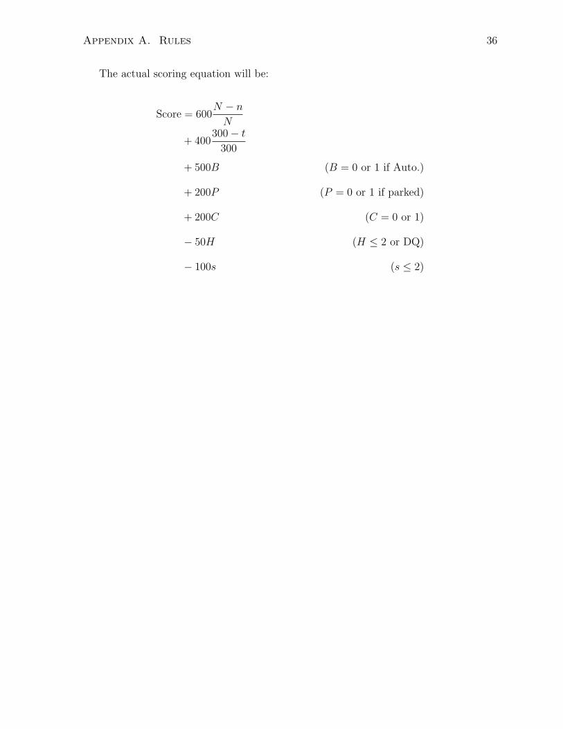
Appendix A. Rules 36
The actual scoring equation will be:
Score = 600N − n
N
+ 400300− t
300
+ 500B (B = 0 or 1 if Auto.)
+ 200P (P = 0 or 1 if parked)
+ 200C (C = 0 or 1)
− 50H (H ≤ 2 or DQ)
− 100s (s ≤ 2)

Appendix A. Rules 37
Definitions of variables in the equation:
t Time required to complete the opera-
tion, in integer seconds (t ≤ 300 or DQ)
N Number of dots on both windows to
START
n Number of dots LEFT at end of run
B Bonus for autonomous operation, bi-
nary value, B = 1 if true
P Team parks device and turns on signal
at end of run, binary, P = 1 if done,
otherwise 0
C Bonus for climbing onto upper window,
C = 1 if true, 0 otherwise (Binary)
H Team touches device during run. 0 ≤
H ≤ 2 or DQ
s Number of water spills, s ≤ 2 or DQ
Maximum score wins.
In the case of a tie, the Winrobo completing the task in the shortest period of time
will be declared the winner.

Bibliography
[1] American Society of Mechanical Engineers, 2008 ASME Student Design Competition,May 2007, http://www.oee.nrcan.gc.ca/equipment/english/page95.cfm?attr=4.
[2] Sangbae Kim, M. Spenko, S. Trujillo, B. Heyneman, V. Mattoli, and M.R. Cutkosky,Whole body adhesion: hierarchical, directional and distributed control of adhesiveforces for a climbing robot, Robotics and Automation, 2007 IEEE International Con-ference (2007), 1268–1273.
[3] Guido La Rosa, Michele Messina, Giovanni Muscato, and R. Sinatra, A low-costlightweight climbing robot for the inspection of vertical surfaces, Mechatronics (2002).
[4] NMB Technologies Corporation, BG0903 centrifugal blower datasheet, 2007,http://www.nmbtc.com/pdf/dcfans/bg0903.pdf.
[5] Matthew Spenko, Mark Cutkosky, Carmel Majidi, Ronald Fearing, Richard Groff,and Keller Autumn, Foot design and integration for bioinspired climbing robots, Un-manned Systems Technology VIII (2006).
[6] Jizhong Xiao, William Morris, Narashiman Chakravarthy, and Angel Calle, Cityclimber: a new generation of mobile robot with wall-climbing capability, UnmannedSystems Technology VIII (2006).
38