wing manul finish2.qxd.r4 -...
TRANSCRIPT
SAFE
STRONG
VERSATILE
Little Giant Ladder Systems®Operating & Safety Instructions
wing_manul_finish2.qxd.r4.dm 10/5/04 4:41 PM Page 1

wing_manul_finish2.qxd.r4.dm 10/5/04 4:41 PM Page 2

1
Dear customers,
Wing Enterprises, Inc. upholds the highest standards in all aspects of business. The key to
our success is our people. We recruit, hire, and train only the best individuals available.
We feel a business is made of bricks and mortar, and our people are the mortar that holds
everything together. Employing only the finest individuals allows Wing Enterprises, Inc. to
produce the world’s finest climbing equipment. We are confident the Little Giant Ladder
System® is the highest quality ladder available worldwide. Every product that comes off
our production line is a “step above the expected,”™ because the people who build our
product share the same vision and adhere to strict quality control measures and processes.
Each member of our manufacturing team has the responsibility and duty to stop the
manufacturing line if the product coming off does not measure up to Wing Enterprises’
strict standards. Our goal is to not only meet your expectations, but also far exceed them.
Customer feedback is paramount to our manufacturing process, and each customer
suggestion and comment is treated as though it were coming from a member of our own
manufacturing team.
Wing Enterprises, Inc. is a mature and well-established company. We have built a loyal
clientele based on the simple premise of providing customers with more than they expect
for their purchase. At the outset of this new millennium, we intend to lengthen our stride
and provide our customers the satisfaction they have never before expected.
If you are already a customer of Wing Enterprises, Inc., we thank you for your business.
If you are currently considering a purchase, we appreciate your consideration of our high
quality products and look forward to doing business with you.
Sincerely,
Harold R. Wing
Founder
FOU
ND
ER’S
MES
SAG
E
wing_manul_finish2.qxd.r4.dm 10/5/04 4:41 PM Page 1
2
Quality First
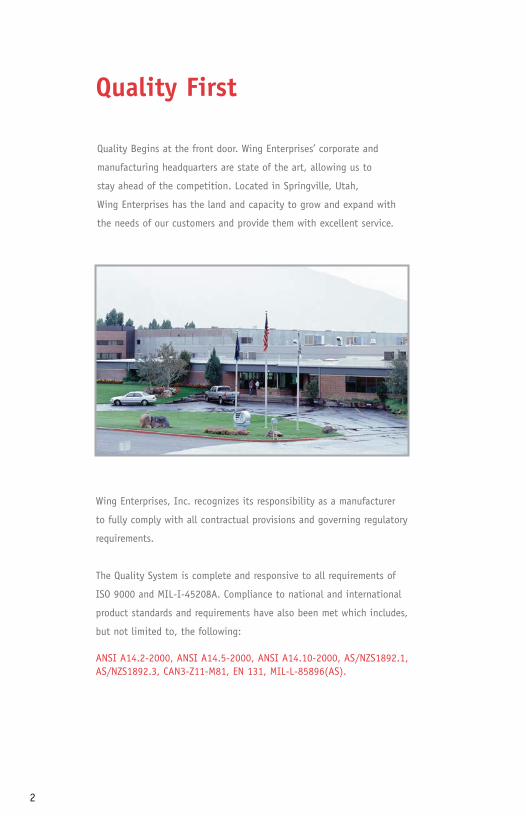
Quality Begins at the front door. Wing Enterprises’ corporate and
manufacturing headquarters are state of the art, allowing us to
stay ahead of the competition. Located in Springville, Utah,
Wing Enterprises has the land and capacity to grow and expand with
the needs of our customers and provide them with excellent service.
Wing Enterprises, Inc. recognizes its responsibility as a manufacturer
to fully comply with all contractual provisions and governing regulatory
requirements.
The Quality System is complete and responsive to all requirements of
ISO 9000 and MIL-I-45208A. Compliance to national and international
product standards and requirements have also been met which includes,
but not limited to, the following:
ANSI A14.2-2000, ANSI A14.5-2000, ANSI A14.10-2000, AS/NZS1892.1,AS/NZS1892.3, CAN3-Z11-M81, EN 131, MIL-L-85896(AS).
ww
w.la
dd
ers
.co
m
wing_manul_finish2.qxd.r4.dm 10/5/04 4:41 PM Page 2
3
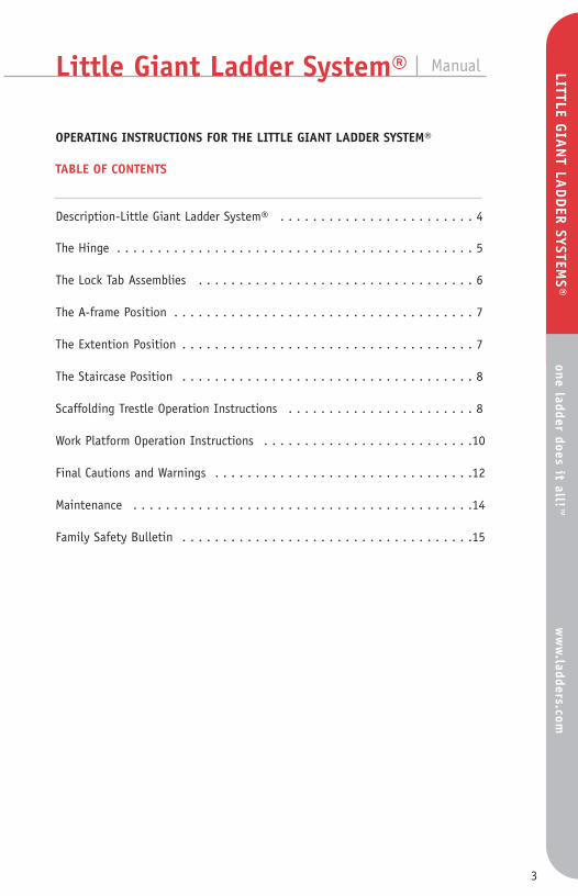
Little Giant Ladder System® Manual
OPERATING INSTRUCTIONS FOR THE LITTLE GIANT LADDER SYSTEM®
TABLE OF CONTENTS
Description-Little Giant Ladder System® . . . . . . . . . . . . . . . . . . . . . . . . 4
The Hinge . . . . . . . . . . . . . . . . . . . . . . . . . . . . . . . . . . . . . . . . . . . . 5
The Lock Tab Assemblies . . . . . . . . . . . . . . . . . . . . . . . . . . . . . . . . . . 6
The A-frame Position . . . . . . . . . . . . . . . . . . . . . . . . . . . . . . . . . . . . . 7
The Extention Position . . . . . . . . . . . . . . . . . . . . . . . . . . . . . . . . . . . . 7
The Staircase Position . . . . . . . . . . . . . . . . . . . . . . . . . . . . . . . . . . . . 8
Scaffolding Trestle Operation Instructions . . . . . . . . . . . . . . . . . . . . . . . 8
Work Platform Operation Instructions . . . . . . . . . . . . . . . . . . . . . . . . . .10
Final Cautions and Warnings . . . . . . . . . . . . . . . . . . . . . . . . . . . . . . . .12
Maintenance . . . . . . . . . . . . . . . . . . . . . . . . . . . . . . . . . . . . . . . . . .14
Family Safety Bulletin . . . . . . . . . . . . . . . . . . . . . . . . . . . . . . . . . . . .15
LITTLE GIA
NT LA
DD
ER SYSTEMS®
one ladder does it all!™w
ww
.ladders.com
ld
d
wing_manul_finish2.qxd.r4.dm 10/5/04 4:41 PM Page 3

4
I. Description - Little Giant Ladder System®
A. The ladder is a multifunctional ladder unit comprised of three basic components-an inner ladder unit assembly and two outer unit assemblies which telescope over the inner.
1. The inner ladder assembly has 2 locking center hinges which allow the entireladder system to be used in the following configurations:
a. A-frameb. Extensionc. Stairwelld. Scaffolding trestlese. Storage
2. Locking mechanisms on the two outer assemblies of the ladder permit theouter telescoping sections of the ladder to be adjusted in length. This lock tabassembly fits in any rung of the inner ladder, allowing foot-by-foot adjustment on either end of the ladder.
B. A table of various working heights for the M-13, M-17, M-22 and M-26 models is as follows.
C. The inner and outer side rails are made of aircraft grade aluminum.
1. There are slip-resistant aluminum rungs on both inner and outer assemblies.2. Both inner and outer assemblies are finished with slip-resistant feet.
Configuration
Working Heights M-13Working Heights M-17Working Heights M-22Working Heights M-26
Storage
3’7”
4’7”
5’7”
6’7”
A-Frame
3’0” to 5’0”
4’0” to 7’0”
5’0” to 9’0”
6’0” to 11’0”
Extension
7’0” to 11’0”9’0” to 15’0”11’0” to 19’0”13’0” to 23’0”
Operating Instructions for Little Giant Ladder System®
CAUTION: SCAFFOLDING TRESTLE CONFIGURATION ONLY TO BE USED WITHOPTIONAL WORK PLATFORM SPREADER ATTACHMENT.
WARNING: INSPECT UPON RECEIPT AND BEFORE EACH USE. NEVER USE A DAMAGED OR BROKEN LADDER.
wing_manul_finish2.qxd.r4.dm 10/5/04 4:41 PM Page 4

5
II. Operating and Adjusting The Ladder
A. The Hinge- located at the top of the ladder when it is in storage position, permitsyou to alter the shape of the ladder. This hinge locks in the following positions (SeeFigures A-1, A-2, and A-3).
1. Unlock the hinge by pushing straight in on the Palm Button until it stays inthe open position on both hinges (See Figures A-4 and A-5).
a. NOTE - If there is pressure on hinge lock pins it will be difficult to unlockthe hinge. To relieve pressure, simply adjust one half of the ladder back andforth until hinge lock pins move without force.
b. NOTE - DO NOT FORCE HINGE LOCK in or out with any tools as it will causepermanent damage to the hinge mechanism. It should never require morethan light pressure to unlock the hinge if the holes are properly aligned.
Figure A-1 Figure A-2 Figure A-3
Figure A-4
LOCKED
Figure A-5
UNLOCKED
PalmButton
HingeLockPins
wing_manul_finish2.qxd.r4.dm 10/5/04 4:41 PM Page 5

6
2. You may now open the ladder to the A-frame position by pulling the two ladderhalves apart until both hinge lock pins snapinto the A-frame locked position.
3. Now place the ladder into the extension position by again pushing straight in on the palm buttons of both hinges (See Figures A-4 and A-5).
Rotate either side of the ladder until thehinge locks snap into their locked position.
To restore the ladder to the storage position,reverse the above procedure. The hinge lock will lock automatically at the A-frame configuration to prevent damage to the ladder or injury to the user.
Use caution and do not let the full weight of the ladder fall on the hinge lock as theladder folds from extension to A-frame configuration. Disengage the hinge locks inthe A-frame position and return the ladder to its storage position.
B. The Lock Tab Assemblies- The secondmechanical component of the ladder system is the LOCK TAB ASSEMBLY. There are four of theseon each ladder. These permit you to change theheight of the ladder (See figure B-1).
C. Adjusting the height of the ladder foruse in the A-frame position.
1. Unlock both hinge locks (See figures
A-4 & A-5).
Hinge
Figure C-1
Figure B-1
Lock Tab Assemblies
CAUTION: HEED THE IMPRINT ON HINGE!“HINGE LOCK MUST BE FULLY IN BEFOREUSING, FAILURE TO DO SO MAY RESULT IN INJURY”
WARNING: DO NOT PULL OUT ALL FOURLOCK TAB ASSEMBLIES UNLESS THE INNER ISHELD, OTHERWISE, IT WILL SLIDE AND HITTHE GROUND OR YOUR FEET.
wing_manul_finish2.qxd.r4.dm 10/5/04 4:41 PM Page 6

7
2. With the ladder in the storage positionand while holding the inner ladder assemblyfirmly in place, pull the four Lock TabAssemblies out of the rung holes of the innerladder and rest them on the side of the outerladder rail (See figures C-1).
3. Raise the inner ladder up to the desired height.
4. At the desired height align the outer holes with the nearest rung hole of the innerladder assembly.
5. Holding the inner and outer ladder at the aligned height with one hand, reinsertthe opposite Lock Tab Assemblies into the rung holes with the other hand.
6. Alternate hands and perform the same operation with the other Lock TabAssemblies (See figure C-3).
7. Open the ladder to the A-frame configuration by pulling the ladderhalves apart until the hinges lock intoplace (See figure A-2 and A-4).
8. To return the ladder to the storage position, reverse the procedures andposition as seen in Figure A-1.
D. Adjusting the height of the ladder in itsextension ladder position.
1. From its stored position, unlock hinge (as Figure D-1
Figure C-3
WARNING: LOCK TAB ASSEMBLIES MUST BEINSERTED INTO AN INNER LADDER ASSEMBLYRUNG HOLE. FAILURE TO DO SO MAY RESULTIN INJURY.
CAUTION: HEED THE WARNING ABOVE EACHLOCK ASSEMBLY
wing_manul_finish2.qxd.r4.dm 10/5/04 4:41 PM Page 7

8
indicated in figures A-4 & A-5) and rotate toextension position until both hinges lock into place.
NOTE: Hinge will first lock in A-frame position, repeat unlocking hinge to rotateit’s extension position.
2. Unlock Lock Tab Assemblies on upper half of the ladder. Grasp the outer ladder, walk backward, allowing the ladder to telescope tothe desired height. If more height is desired,extend the lower half of the ladder (see figure D-1).
3. To store the ladder from its extensionposition, reverse the above sequence startingwith the lower half of the ladder.
E. Staircase Position.
1. Adjust ladder to desired height (reviewsection concerning adjusting the height ofthe ladder for use in the A-frame position.)
2. Then adjust the side desired for properalignment to fit the staircase (see
figure E-1).
Figure E-1
Figure F-1
Figure F-2 Figure F-4Figure F-3
WARNING: DO NOT REMOVE LOCK TABASSEMBLIES FROM LOWER HALF OF THE LADDER WITHOUT HAVING A SECURE HOLDON THE INNER SECTION.
wing_manul_finish2.qxd.r4.dm 10/5/04 4:41 PM Page 8
9
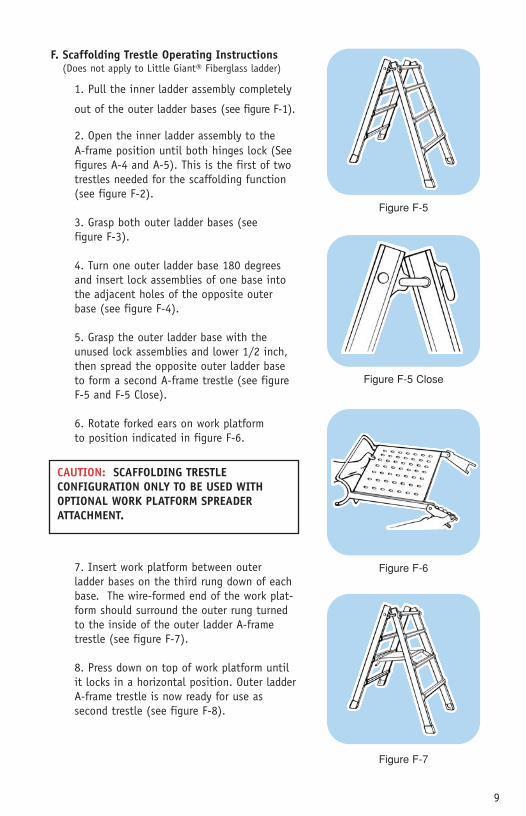
F. Scaffolding Trestle Operating Instructions
1. Pull the inner ladder assembly completely
out of the outer ladder bases (see figure F-1).
2. Open the inner ladder assembly to the A-frame position until both hinges lock (See figures A-4 and A-5). This is the first of two trestles needed for the scaffolding function (see figure F-2).
3. Grasp both outer ladder bases (see figure F-3).
4. Turn one outer ladder base 180 degrees and insert lock assemblies of one base intothe adjacent holes of the opposite outerbase (see figure F-4).
5. Grasp the outer ladder base with theunused lock assemblies and lower 1/2 inch,then spread the opposite outer ladder baseto form a second A-frame trestle (see figureF-5 and F-5 Close).
6. Rotate forked ears on work platform to position indicated in figure F-6.
7. Insert work platform between outer ladder bases on the third rung down of eachbase. The wire-formed end of the work plat-form should surround the outer rung turnedto the inside of the outer ladder A-frametrestle (see figure F-7).
8. Press down on top of work platform untilit locks in a horizontal position. Outer ladder A-frame trestle is now ready for use as second trestle (see figure F-8).
Figure F-5
Figure F-6
Figure F-7
Figure F-5 Close
CAUTION: SCAFFOLDING TRESTLE CONFIGURATION ONLY TO BE USED WITHOPTIONAL WORK PLATFORM SPREADERATTACHMENT.
(Does not apply to Little Giant® Fiberglass ladder)
wing_manul_finish2.qxd.r4.dm 10/5/04 4:41 PM Page 9

10
Figure F-8 Figure F-9
Figure G-1 Figure G-2
9. Space the two trestles and place an appropriate scaffolding plank on the set ofrungs at the desired working height (see figure F-9).
G. Work Platform Operating Instructions
1. Tighten or loosen bolts until brackets move stiffly (see figure G-1).
2. Adjust to fit ladder rung (see figure G-2).
3. Place platform at desired height (see figure G-3).
4. Push platform forward and step up through the rung above platform (see figure G-4).
WARNING: MAKE CERTAIN WORK PLATFORM IS LOCKEDINTO POSITION BEFORE CLIMBING, WING ENTERPRISESINC. ASSUMES NO LIABILITY FOR DAMAGE OR INJURYWHICH MAY RESULT BY FAILING TO FOLLOW ALL PRECEDING INSTRUCTIONS CORRECTLY.
CAUTION: HEED THE WARNING LABEL PLACED ON THE OUTER LADDER HALFREGARDING THE USE OF THE WORK PLATFORM AS A SPREADER ATTACHMENT.
wing_manul_finish2.qxd.r4.dm 10/5/04 4:41 PM Page 10

11
Figure G-3 Figure G-4 Figure G-5
Figure G-6 Figure G-7 Figure G-8
5. Push platform back with toe (see figure G-5) until the forward tip of the platform rests against the rung.
6. Check to ensure platform is securely in place before putting full weight on it(see figure G-6).
7. When through, step to rung above work platform and push work platform forward with toe. Step down through work platform (see figure G-7).
8. The above instructions apply to the A-frame ladder also. The platform may alsobe used as a utility shelf (see figure G-8).
CAUTION: HEED THEWARNING LABEL PLACEDON THE WORK PLATFORM.
wing_manul_finish2.qxd.r4.dm 10/5/04 4:42 PM Page 11

12
H. Final Cautions And Warning
1. When adjusting hinges or Lock Tab Assemblies, keep body parts and clothingout of the working mechanisms. These mechanisms are constructed of heavy dutymaterials and can pinch if carelessly adjusted.
2. When telescoping the inner ladder within the outer bases, never allow clothingor body parts to be placed between the rungs. Always hold the ladder with bothhands on the vertical upper rails or hinges of the ladder while telescoping up ordown.
3. When using ladders around electricity or on projects involving any type of electrical work, use caution and ensure that the ladder does not come in contactwith electrical circuits.
4. When using ladders, be sure to:a. Set all four feet on firm level surfaceb. Keep steps dry and cleanc. Wear slip-resistant shoesd. Keep body centered between both siderailse. Read additional instructions on the ladder
5. When using extension ladder, the proper working angle requires that the distance from ladder base to the base of the support wall must be 1/4 the working length of the ladder, ie: 1 foot out from wall for every four feet inheight. This will make sure the foot doesn’t slip.
6. The Little Giant® Ladders are offered in different duty ratings* in accordance with applicable ANSI and OSHA standards. Do not exceed safe working limits (See table below).
7. The rungs of the Little Giant Ladder System® are so constructed that the surface of the rungs is parallel to the surface upon which the ladder stands when in proper use.
CAUTION: NEVER CLIMB THE BACK OF THE LADDER IN THE EXTENSION POSITIONAS INDICATED ON WARNING LABEL PLACED ON THE INSIDE OF THE INNER LADDER ASSEMBLY.
TYPE DUTY RATING WORKING LOADType IAA Special Duty 375 LBS.Type IA Industrial - Extra Heavy 300 LBS.Type I Industrial - Heavy 250 LBS.
wing_manul_finish2.qxd.r4.dm 10/5/04 4:42 PM Page 12

13
Dangers and Warnings
wing_manul_finish2.qxd.r4.dm 10/5/04 4:42 PM Page 13

14
I. Maintenance
1. To ensure smooth operation, lubricate the hinge mechanism and lock tabassemblies with light machine oil every six months and prior to long term storage.This should be performed more often as use dictates, and under extreme weatherconditions. (WD40 works well)
2. Always store the ladder in a dry location out of the weather. This will help toensure that your Little Giant will provide you a lifetime of service.
3. Keep rails clean so that ladder will slide easily.
4. Keep hinge mechanism free of dirt, salt spray, or other contaminants thatcould prevent proper operation.
5. Replace inner and outer feet as required to ensure safety.
6. Check all components to be sure they operate correctly.
7. Replace labels with label kit when labels become obscure, defaced, missing or difficult to read.
wing_manul_finish2.qxd.r4.dm 10/5/04 4:42 PM Page 14

15
Ladders present a serious safety hazard if not used properly. FALLS HURT!
A Family Safety Bulletin FAM
ILY SAFETY B
ULLETIN
one ladder does it all!™w
ww
.ladders.com
wing_manul_finish2.qxd.r4.dm 10/5/04 4:42 PM Page 15

16
• Use a sound ladder with safety feet.
• Make sure it is firm and steady with no defective rungs, braces or side rails.
• Get help in carrying and setting up heavy extension ladders.
• On a step ladder, never climb or standon the top two steps.
• Make sure the ladder is long enough.
• On straight ladders, don’t stand on thetop four rungs.
• Set the ladder up on level. Ladders can’t adjust to a side sloping surface and there’s a good chance that a ladder set on a slant will tip over sideways.
• A ladder “STABILIZER,” which fits on the top of a straight ladder, lessens chances of tipping and allows better working space.
• Do NOT over-reach.
wing_manul_finish2.qxd.r4.dm 10/5/04 4:42 PM Page 16

17
• On soft ground use a wide board (6 inches width or more) to keep the ladder legs from sinking into the ground and slipping.
• Set the ladder at the proper angle; when a ladder is too far out it may slip out at the bottom.
• A ladder placed too close may tip over backward. Place the bottom one foot out for each four feet of height.
• Tying the ladder to a firm support near the top will help to prevent slipping or tipping.
wing_manul_finish2.qxd.r4.dm 10/5/04 4:42 PM Page 17

18
SOME OTHER SAFETY TIPS:
• Be certain that metal ladders do not touch electrical power lines.
• Put a brace at the bottom of the ladder or have someone hold the ladder to keep it from slipping.
• Don’t place the ladder where it can slip or be shaken--for example,by a swaying tree.
• Beware of high winds.
wing_manul_finish2.qxd.r4.dm 10/5/04 4:42 PM Page 18

19
1) Use a sound ladder, long enough for the job.
2) If possible, use a ladder with safety feet.
3) Get help with a heavy ladder.
4) Set the ladder up on the level so it won’t shift or sway.
5) Use a wide board under the feet if the ground is soft.
6) Set a straight ladder at the proper angle (4 to 1 ratio).
7) Open a stepladder fully to engage the side hinges.
8) Avoid working around power lines with a ladder or your body.
9) Make sure ladder rungs and shoe soles are not slippery.
10) Face the ladder when you climb.
11) Stand well below the top of the ladder.
12) Tie the ladder at the top, if possible.
13) Never overreach. Move the ladder!
14) Always hold the ladder with one hand.
15) Haul tools up on a line rather than carrying them.
16) Be as careful on a short stepladder as on a 30 foot extension ladder.
17) False security can lead to carelessness and falls which can cause painful injuries.
BEFORE YOU OR YOUR FAMILY MEMBERS USE A LADDER, REVIEW THESETIPS, USE THEM!
SOUND LADDER RIGHT LENGTH SET FIRM & LEVEL4 TO 1 ANGLE USE RIGHT WAY
wing_manul_finish2.qxd.r4.dm 10/5/04 4:42 PM Page 19

20
wing_manul_finish2.qxd.r4.dm 10/5/04 4:42 PM Page 20

21
LITTLE GIANT® MXZ TELESCOPING A-FRAME ALUMINUM LADDER OPERATINGAND SAFETY INSTRUCTIONS
TABLE OF CONTENTS
Description-Little Giant® MXZ Telescoping A-Frame Ladder Aluminum . . . . . . . . . . . . . . . . . . . . . . . . . . . . . . . . . . . . . . .22
Operating and adjusting the ladder . . . . . . . . . . . . . . . . . . . . . . . . . . . .22
The hinge . . . . . . . . . . . . . . . . . . . . . . . . . . . . . . . . . . . . . . . . . . . .22
The lock assembly . . . . . . . . . . . . . . . . . . . . . . . . . . . . . . . . . . . . . . .23
Adjusting the A-frame ladder . . . . . . . . . . . . . . . . . . . . . . . . . . . . . . . .24
Adjusting the staircase ladder . . . . . . . . . . . . . . . . . . . . . . . . . . . . . . .25
Warranty statement and final inspection . . . . . . . . . . . . . . . . . . . . . . . .31
MXZ Industrial-extra heavy 300 lbs rated
LITTLE GIA
NT® M
XZone ladder does it all!™
ww
w.ladders.com
wing_manul_finish2.qxd.r4.dm 10/5/04 4:42 PM Page 21
22
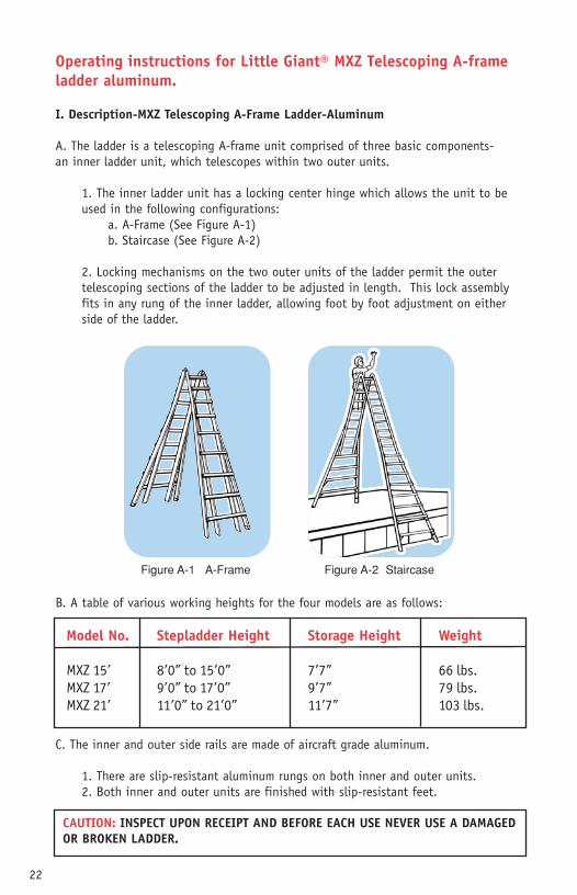
Operating instructions for Little Giant® MXZ Telescoping A-frameladder aluminum.
I. Description-MXZ Telescoping A-Frame Ladder-Aluminum
A. The ladder is a telescoping A-frame unit comprised of three basic components- an inner ladder unit, which telescopes within two outer units.
1. The inner ladder unit has a locking center hinge which allows the unit to beused in the following configurations:
a. A-Frame (See Figure A-1)b. Staircase (See Figure A-2)
2. Locking mechanisms on the two outer units of the ladder permit the outertelescoping sections of the ladder to be adjusted in length. This lock assemblyfits in any rung of the inner ladder, allowing foot by foot adjustment on eitherside of the ladder.
B. A table of various working heights for the four models are as follows:
C. The inner and outer side rails are made of aircraft grade aluminum.
1. There are slip-resistant aluminum rungs on both inner and outer units. 2. Both inner and outer units are finished with slip-resistant feet.
Model No.
MXZ 15’
MXZ 17’
MXZ 21’
Storage Height
7’7”
9’7”
11’7”
Stepladder Height
8’0” to 15’0”
9’0” to 17’0”
11’0” to 21’0”
Weight
66 lbs.
79 lbs.
103 lbs.
Figure A-1 A-Frame Figure A-2 Staircase
CAUTION: INSPECT UPON RECEIPT AND BEFORE EACH USE NEVER USE A DAMAGEDOR BROKEN LADDER.
wing_manul_finish2.qxd.r4.dm 10/5/04 4:42 PM Page 22
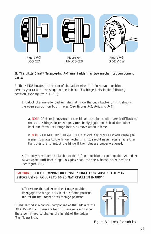
II. The Little Giant® Telescoping A-Frame Ladder has two mechanical componentparts:
A. The HINGE located at the top of the ladder when it is in storage position, permits you to alter the shape of the ladder. This hinge locks in the following position. (See figures A-1, A-2)
1. Unlock the hinge by pushing straight in on the palm button until it stays inthe open position on both hinges (See figures A-3, A-4, and A-5).
a. NOTE- If there is pressure on the hinge lock pins it will make it difficult tounlock the hinge. To relieve pressure simply jiggle one half of the ladderback and forth until hinge lock pins move without force.
b. NOTE - DO NOT FORCE HINGE LOCK out with any tools as it will cause per-manent damage to the hinge mechanism. It should never require more thanlight pressure to unlock the hinge if the holes are properly aligned.
2. You may now open the ladder to the A-frame position by pulling the two ladderhalves apart until both hinge lock pins snap into the A-frame locked position.(See figure A-1)
3.To restore the ladder to the storage position, disengage the hinge locks in the A-frame position and return the ladder to its storage position.
B. The second mechanical component of the ladder is the LOCK ASSEMBLY. There are four of these on each ladder. These permit you to change the height of the ladder(See figure B-1).
23
Figure A-3LOCKED
Figure A-4UNLOCKED
Figure A-5SIDE VIEW
CAUTION: HEED THE IMPRINT ON HINGE! “HINGE LOCK MUST BE FULLY INBEFORE USING, FAILURE TO DO SO MAY RESULT IN INJURY.”
Figure B-1 Lock Assemblies
wing_manul_finish2.qxd.r4.dm 10/5/04 4:42 PM Page 23
24
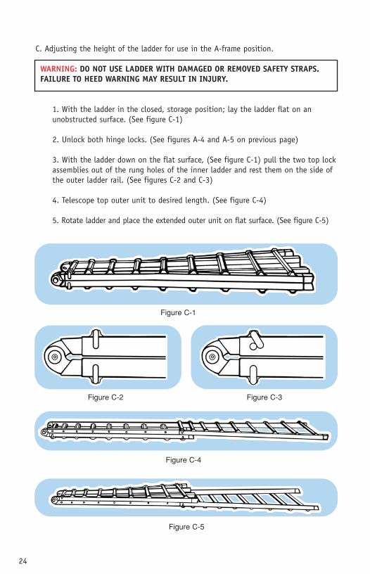
C. Adjusting the height of the ladder for use in the A-frame position.
1. With the ladder in the closed, storage position; lay the ladder flat on an unobstructed surface. (See figure C-1)
2. Unlock both hinge locks. (See figures A-4 and A-5 on previous page)
3. With the ladder down on the flat surface, (See figure C-1) pull the two top lockassemblies out of the rung holes of the inner ladder and rest them on the side ofthe outer ladder rail. (See figures C-2 and C-3)
4. Telescope top outer unit to desired length. (See figure C-4)
5. Rotate ladder and place the extended outer unit on flat surface. (See figure C-5)
Figure C-1
Figure C-5
Figure C-4
Figure C-2 Figure C-3
WARNING: DO NOT USE LADDER WITH DAMAGED OR REMOVED SAFETY STRAPS.FAILURE TO HEED WARNING MAY RESULT IN INJURY.
wing_manul_finish2.qxd.r4.dm 10/5/04 4:43 PM Page 24

25
6. Telescope remaining outer unit to desired length.
7. To raise the ladder, brace the feet against the wall and lift the hinged top; walk (rung by rung) the ladder to a vertical position. (See figures C-6 and C-7)
8. Open the ladder to the A-frame configuration by pulling the ladder halves apartuntil the hinges lock into place.
Figure C-6
Figure C-7
9. To return ladder to a storage position:
a. In the A-frame position tip ladder tothe side and lower to a flat surface.
b. Unlock both hinges and bring the ladder halves together.
c. Rotate ladder and place flat on surface.
d. Reverse procedures of steps C-1 through C-6.
D. Adjusting the ladder in the staircase position.
1. Adjust ladder to desired height. (See stepsC-1 through C-5)
2. Then adjust side desired for proper alignment to fit the staircase (See figure D-1).
CAUTION: HEED THE WARNING LABEL PLACED ABOVE EACH LOCK ASSEMBLY.
Figure D-1
wing_manul_finish2.qxd.r4.dm 10/5/04 4:43 PM Page 25
26
wing_manul_finish2.qxd.r4.dm 10/5/04 4:43 PM Page 26

27
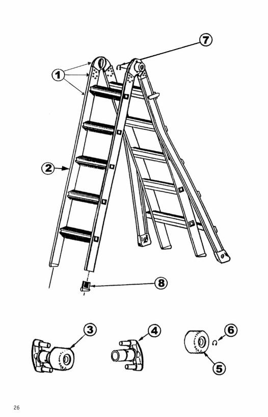
REPLACEM
ENT PA
RTSone ladder does it all!™
ww
w.ladders.com
wing_manul_finish2.qxd.r4.dm 10/5/04 4:43 PM Page 27

28
Little Jumbo™ ladders are built tothe industry’s most exacting specifi-cations. Two-step, three-step, andfour-step models all incorporatewide, slip-resistant step treads formaximum stability. All three modelsalso offer optional fold-up safetybars for added security.
All models are made from a rugged,corrosion-resistant aluminum alloy--built to last yet lightweight andeasy to handle.
Little Jumbo™ ladders fold to a slim3” depth. Steps pivot verticallywhile the framework tucks togetherfor convenient storage. Even withthose models incorporating theoptional safety bar, folded depth is less than 5”.
The Little Jumbo™ Compact StepStool is the latest in the line of products in the Wing Enterprises,Inc. family. The Compact Step issimilar to the original Little Jumbo™Step Stool. Both are made of highquality aluminum with wide steps foreasy use at whatever height you maychoose. The heights of the steps are the same on both model lines.The main difference is that whenstored the Compact Step is one-thirdthe size of a regular Little Jumbo™.
The Compact Step also has a spring-loaded release for easier closing. The Compact Step can doanything a Little Jumbo™ does andmore.
LITTLE JUMBO™ SAFETY STEP
Little Jumbo™ Safety Step
wing_manul_finish2.qxd.r4.dm 10/5/04 4:43 PM Page 28

29
AccessoriesTELESCOPING PLANKConverts any of our ladders into a simple scaffolding system. This high-strength plank stores and hauls in nearlyhalf of its extended length. It’s lightenough for easy setup and handling andfeatures a slip-resistant surface for safety.Available in 6’ to 9’, 8’ to 13’,and 10’ to 16’ lengths. 250 lbs. capacity.
WING SPAN™When working around windows, rain gutters, bushes, overhangs and otherobstacles, the Wing Span™ extra width and individually adjustable legs add even more versatility to any of the Little Giant Ladders.
LEG LEVELERWhen the Little Giant has to be used onan uneven surface, the leg leveler offers a safe, stable solution. The leg leveler is made to meet the same extra heavy-duty standards as our ladders and attaches easily.
WORK PLATFORMThe moveable work platform fits on anyrung and is designed to support up to300lbs of anything from paint to people.Our unique design allows it to be tuckedaway when not needed yet easily movedinto place with your foot when needed.
LITTLE JUM
BO
™ SA
FETY STEPone ladder does it all!™
ww
w.ladders.com
wing_manul_finish2.qxd.r4.dm 10/5/04 4:43 PM Page 29

30
wing_manul_finish2.qxd.r4.dm 10/5/04 4:43 PM Page 30

31
Warranty - Wing Enterprises, Inc.
Little Giant Ladder System® Limited WarrantyOur warranty is backed by over 30 years in the ladder business
We sincerely believe that our ladder is the best in the world. We put ourproducts through rigorous tests to ensure that the ladder you trust is built tothe highest standards. You will probably never encounter a problem with thisLittle Giant® Ladder, but in the unlikely event that within the warranty period(see table below) from the date of the original purchase, a problem caused bydefects in either workmanship or materials is discovered, we’ll be happy torepair or replace, at our option and without cost to the original purchaser. Allwe ask is that you get your ladder to our manufacturing facility in Springville,Utah. If it is determined that the problem is covered by our warranty, we’ll takecare of the rest. All freight to and from the factory is to be paid by the customer. If a replacement is necessary and your product is no longer available,a comparable product will be substituted.
Little Giant® ladders are tested to withstand normal wear and tear, but are notindestructible and can be damaged by misuse. Our warranty, just like other warranties worldwide, will not cover wear and tear, misuse and/or abusive treatment. But we do ensure a timely resolution at a fair price. Misuse mayinclude, but is not limited to, damage by vehicles, tools, people, animals, fallingobjects, acts of God, and the using of a Little Giant® in any way, shape or formnot as instructed in the ladder warning/instruction labels and owner’s manual.If you do not have an owner’s manual please contact us and we will send oneright out to you.
Before you ship your product back for warranty review, please call us at 1-800-453-1192 to obtain a Return Merchandise Authorization or RMA from ourCustomer Service Department. Return your ladder prepaid, insured, and in acarton. Include your name, address, phone number, proof of purchase, and abrief description of the problem. The address to return the product is: WingEnterprises, Inc., Attention: Warranty Department, 1325 West Industrial Circle,Springville, Utah 84663. You can access more information on all Little Giant®Ladders by going to our web site: www.ladders.com.
This shall be in lieu of any other warranty, expressed or implied, including, butnot limited to, any implied warranty of merchantability or fitness for a particu-lar purpose. The liability of Wing Enterprises, Inc. under this warranty shall belimited solely to repair or replacement of the ladder within the warranty period;and Wing Enterprises, Inc. shall not be liable, under any circumstances, for con-sequential or incidental damages, including but not limited to, personal injuryor labor costs. Some states do not permit the exclusion or limitation of inciden-tal or consequential damages, so this exclusion may not apply to you. This war-ranty gives you specific legal rights and you may have other legal rights, whichmay vary, from state to state. This warranty is effective as of January 1, 2004.Manufacturing specifications are subject to change without notice.
WA
RRAN
TYone ladder does it all!™
ww
w.ladders.com
wing_manul_finish2.qxd.r4.dm 10/5/04 4:43 PM Page 31

32
Under no circumstances will Wing Enterprises, Inc. be responsible for any expense inconnection with any repairs made by anyone other than the factory or authorized ser-vice station unless such repairs have been specifically authorized in writing by WingEnterprises, Inc.
The original Little Giant Ladder System® has been around since 1972, and has providedsatisfaction to millions of customers. So rest assured, if you ever need assistance withyour ladder, we’ll still be here to see that you’re taken care of.
View the warranty for your ladder model below.
FINAL INSPECTION
The Little Giant® Ladder is the best ladder obtainable anywhere, Quality Control checkshave been made during each manufacturing operation to ensure your ladder meets ourhigh manufacturing standards. The following items have been individually checked andapproved before boxing.
1) Positive locking of hinge in each opening.
2) Smooth operation of lock tab assemblies..
3) Inner ladder assembly slides freely within outer ladder assembly.
4) Both inner and outer ladder assemblies stand flat on all fours (where applicable).
5) All component parts are in place.
6) All workmanship is of good quality.
I sincerely hope you enjoy your Little Giant®.
TYPE DESCRIPTION PERIOD
Type IA Original Little Giant Ladder System® LifetimeType IA Ultra Fiberglass Little Giant Ladder System® 1 yearType IA MXZ Little Giant Ladder System® 5 yearsType IAA Little Giant Ladder System® 5 yearsType I Little Giant Ladder System® 5 years
WARRANTIES
wing_manul_finish2.qxd.r4.dm 10/5/04 4:43 PM Page 32

33
wing_manul_finish2.qxd.r4.dm 10/5/04 4:43 PM Page 33

www.ladders.com
toll free: 800-453-1192
phone: 801-489-3684
fax: 801-489-3685
© 1986 Wing Enterprises, Inc.
p/n 51136
MADE IN USA
WING ENTERPRISES, INCORPORATED
1325 West Industrial Circle
Post Office Box 3100
Springville, Utah 84663-3100
wing_manul_finish2.qxd.r4.dm 10/5/04 4:43 PM Page 34