wings to your thoughts….. smart android … android wheelchair controller design.pdf · in this...
TRANSCRIPT

Webpage: www.ijaret.org Volume 3, Issue V, May 2015 ISSN 2320-6802
INTERNATIONAL JOURNAL FOR ADVANCE RESEARCH IN
ENGINEERING AND TECHNOLOGY WINGS TO YOUR THOUGHTS…..
Page 42
Abstract: This project is related to the android-based wheelchair controller. The system is designed to control a
wheelchair by using an android device. The objective of this project is to facilitate the movement of disable people or
handicapped and also the senior people who are not able to move well. The result of this design will allow the special
people to live a life with less dependence on others. Android technology is a key which may provide a new approach
of human interaction with machines or tools. Thus their problem can be solved by using android technology to control
the movement of a wheelchair. In this project, Basic4android interface is designed to program the android device that
will be able to control the movement of wheelchair. This project integrated IOIO board and direct current motor to
create the movement of wheelchair. The results of this project showed that this project can be used for future research
works and to design excellence innovation that meets market need and public interest.
Keywords: Android, Direct Current, IOIO Board, Motor.
1. INTRODUCTION While the needs of many individuals with disabilities
can be satisfied with power wheelchairs, some
members of the disabled community find it is difficult
or impossible to operate a standard power wheelchair.
This project could be part of an assistive technology. It
is for more independent, productive and enjoyable
living. Android-based wheelchair controller is a system
where the DC motor is used to move the wheelchair.
Nowadays, handicapped people face problem to
control wheelchair by themselves. Sometimes they
need other people to help them. This project will
provide a new way to control the movement of
wheelchair such as turn direction to left, right, forward
and reverse direction. The overall wheelchair
operation uses DC motor and motor driver module
combines with microcontroller system for instance
IOIO board [1]-[2]. Android-based wheelchair
controller that consists of android device and a control
box that can be attached to standard wheelchairs to
control the movement by using a DC motor. Bluetooth
communication protocol is used to communicate
sensory and command information between the
android device and the control box [3].
There are 4 options for basic motions of a wheelchair
to be applied by the user [4]. The four conditions of
the wheelchair can be described as the following:
a. Moving forward
b. Moving backward
c. Turning to the right
d. Turning to the left
This project also provided a controller to the electrical
appliance by using radio frequency as a wireless
connection between control box and electrical
appliance. Figure 1 shows the block diagram for
overall of the project.
Figure 1 Block diagram for overview project
Smart Android Wheelchair Controller Design K. A. A. Aziz
1, M. H. Mustafa
2, N. M. Z. Hashim
3,
N. R. M. Nuri4, A. F. Kadmin
5, A. Salleh
6
1, 2, 4, 5 Faculty of Engineering Technology,
Universiti Teknikal Malaysia Melaka,
76100 Hang Tuah Jaya, Durian Tunggal, Melaka, Malaysia. [email protected], [email protected], [email protected]
3, 6 Center for Telecommunication Research & Innovation (CeTRI),
Faculty of Electronic and Computer Engineering,
Universiti Teknikal Malaysia Melaka,
76100 Hang Tuah Jaya, Durian Tunggal, Melaka, Malaysia. [email protected], [email protected]
Webpage: www.ijaret.org Volume 3, Issue V, May 2015 ISSN 2320-6802
INTERNATIONAL JOURNAL FOR ADVANCE RESEARCH IN
ENGINEERING AND TECHNOLOGY WINGS TO YOUR THOUGHTS…..
Page 43
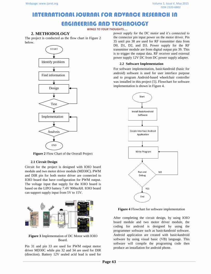
2. METHODOLOGY The project is conducted as the flow chart in Figure 2
below.
Figure 2 Flow Chart of the Overall Project
2.1 Circuit Design
Circuit for the project is designed with IOIO board
module and two motor driver module (MD30C). PWM
and DIR pin for both motor driver are connected to
IOIO board that have configuration for PWM output.
The voltage input that supply for the IOIO board is
based on the LIPO battery 7.4V 900mAH. IOIO board
can support supply input from 5V to 15V.
Figure 3 Implementation of DC Motor with IOIO
Board.
Pin 31 and pin 33 are used for PWM output motor
driver MD30C while pin 32 and 34 are used for DIR
(direction). Battery 12V sealed acid lead is used for
power supply for the DC motor and it’s connected to
the connector pin input power on the motor driver. Pin
35 until pin 38 are used for RF transmitter data from
D0, D1, D2, and D3. Power supply for the RF
transmitter module are from digital output pin 39. This
is to trigger the output data. RF receiver used external
power supply 12V DC from DC power supply adapter.
2.2 Software Implementation
For software implementation, basic4android (basic for
android) software is used for user interface purpose
and to program Android-based wheelchair controller
was installed in this project [5]. Flowchart for software
implementation is shown in Figure 4.
Figure 4 Flowchart for software implementation
After completing the circuit design, by using IOIO
board module and two motor driver module, the
coding for android is designed by using the
programmer software such as basic4android software.
Android application are created with basic4android
software by using visual basic (VB) language. This
software will compile the programing code then
produce an installation for android phone.
START
Identify problem
Find information
Design
Implementation
Test
Analysis
END

Webpage: www.ijaret.org Volume 3, Issue V, May 2015 ISSN 2320-6802
INTERNATIONAL JOURNAL FOR ADVANCE RESEARCH IN
ENGINEERING AND TECHNOLOGY WINGS TO YOUR THOUGHTS…..
Page 44
Figure 5 Basic Design for Android Phone by Using
Basic4android Software
2.3 Hardware implementation
In hardware implementation, there are two part
involved which are mechanical part and electronic
part. Mechanical part is about how the wheelchair is
developed and modified [6]-[8]. In electronic part, it
consists of the development of control box [9]-[12].
The control box consist of IOIO board and motor
driver as shown in Figure 6 below.
Figure 6 Control Box
There are two board of motor driver and IOIO board
are placed into the control box. User can switches
ON/OFF easily because switches for IOIO board and
battery supply are below the chair that can be achieved
by the user’s hand. There are RF transmitter module to
communicate with the RF receiver module[13]-[15].
This part is to control the electrical appliances directly
from android phone.
Figure 7 Battery Box
Battery 12V 7AH are placed into the battery box to
ease the user to recharge the battery. There are pin
outside the battery box for charging pin. User can
recharge the battery without have to open the battery
box.
Figure 8 Android-Based Wheelchair Controller
The connection between motor driver and the 12V
battery are using multi-core wire 2.5mm. Multi-core
wire 2.5mm are used to support high ampere supply to
the motor driver.
Figure 9 RF Receiver Circuit with Output Relay
Figure 9 shows the RF receiver module with the relay
output to control the appliance from the android
phone. Relay act as a switch to turn ON or OFF the
electrical appliance. The connection of the relay to
control the electrical appliance is parallel with the
switch on the 3 pin plug socket. Figure 10
demonstrates the internal connection of the 3pin plug
socket.

Webpage: www.ijaret.org Volume 3, Issue V, May 2015 ISSN 2320-6802
INTERNATIONAL JOURNAL FOR ADVANCE RESEARCH IN
ENGINEERING AND TECHNOLOGY WINGS TO YOUR THOUGHTS…..
Page 45
Figure 10 Internal Connection of the 3-Pin Plug
Socket
3. RESULT AND ANALYSIS There are few tests have been done to find the analysis
for this project.
Movement of Wheelchair
Movement of the wheelchair are according to the pin
configuration at motor driver. There are 3 pins to
control the DC motor which are pin PWM, pin DIR,
and GND pin. PWM and DIR pin are according to the
truth table.
Table 1 Pin Configuration of the Motor Driver
Pin 2
(PWM)
PIN 3
(DIR)
OUT
A
OUT
B MOTOR
Low X (Don’t
Care) Low Low Stop
High Low High Low Clockwise
High High Low High Anti-
Clockwise
Based on Table 1 the movement of the wheelchair with
the wheel direction and one wheel will going inversely
when turning to the right or left.
Table 2 Declaration of the Movement of the
Wheelchair
Button
Command
Left
Wheel
Right
Wheel
Condition Of
Wheelchair
Forward Forward
Move
Forward
Reverse Reverse Reverse
Forward Reverse
Turning To
The Right
Reverse Forward
Turning To
The Left
- Stop Stop Stop
Pin 31 until pin 34 are used as a pin controller for DC
motor. This condition can be refer to the truth table of
the motor driver MD30C.
Table 3 The Truth Table for Each Movement
Button
Command
Right Wheel Left Wheel
Condition
Of
Wheelchair
PIN
31
PWM
PIN
32
DI
R
PIN
33
PWM
PIN
34
DIR
1 0 1 0
Move
Forward
1 1 1 0
Turning To
The Right
1 1 1 1 Reverse
1 0 1 1
Turning To
The Left
-
0 0 0 0 Stop
Compass Analysis
Make an analysis to compare between the android
phone (electronic compass) compass and actual
compass (analog compass). On this analysis, 8 poles
are taken into consideration for compass analysis.
Firstly, synchronize the paper that have a printed
compass with the actual compass device.
Figure 11 Printed Compass with the Actual
Compass
Fix the paper to the right position and make sure the
paper are not moving. Place the phone according to the
position needed by following printed paper that have 8
pole.
Figure 12 Placing Phone with the Printed Compass
Webpage: www.ijaret.org Volume 3, Issue V, May 2015 ISSN 2320-6802
INTERNATIONAL JOURNAL FOR ADVANCE RESEARCH IN
ENGINEERING AND TECHNOLOGY WINGS TO YOUR THOUGHTS…..
Page 46
Collect all the data and compare it with the actual
compass to the Table 4. Electronic compass have a bit
difference value with the actual compass.
Table 4 Comparison between Electronic Compass
Reading and Actual Compass Reading
Direction ( °) Degree ( °)
North (360°) 357.99°
North east (45°) 45.86°
East (90°) 93.97°
South east (135°) 139.60°
South (180°) 179.99°
South west (225°) 222.51°
West (270°) 267.41°
North west (315°) 313.05°
The position of the wheelchair are important to make
sure the wheelchair will turning to the right direction.
Table below shown the position of wheelchair that
need to make a turn to find a Qibla direction.
Table 5 Range Searching for Qibla Direction
Wheelchair position angle
(X) Movement of wheelchair
123° < X < 290° Turn to right
X < 123° Turn to left
X > 330° Turn to left
Table 6 Angle Range for Qibla Direction
Qibla Direction Angle (X) Movement of Wheelchair
285° > X > 255° Stop and turn to left for 3
second
315° > X > 285° Stop and turn to right for 3
second
290° > X > 280° Stop
Table 6 above shown the angle range for Qibla
direction to stop the wheelchair at the correct
direction. This Qibla direction are not too accurate
because of the inertia that happen when turning the
wheelchair to the right or left. To reduce the distance
wheelchair strayed from the direction of Qibla, this
project is added with other coding in order to make the
attraction towards the opposite rotation when rotation
of the wheelchair occur. If wheelchair are turning to
right, when it reach to the Qibla direction of angle the
wheelchair will stop and make a turning to left for 3
second. This will make the motor stop from going far
from Qibla direction. However, this system still not
make the wheelchair stop to the correct angle because
it still have a large inertia value when battery in fully
charge or vice versa. To make sure user in the correct
direction of Qibla, this project added buzzer when the
wheelchair reach at the correct angle of Qibla. User
also can manually turn the wheelchair to find the
correct direction of Qibla that guided by buzzer that
sounds right on the direction of Qibla.
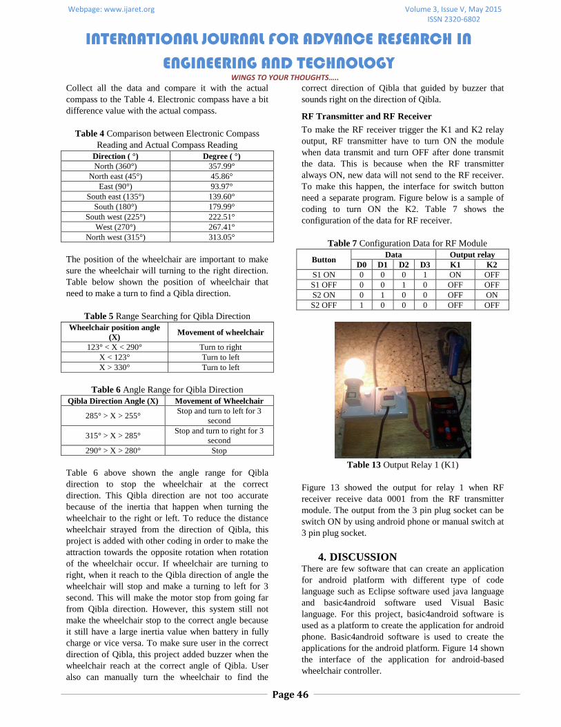
RF Transmitter and RF Receiver
To make the RF receiver trigger the K1 and K2 relay
output, RF transmitter have to turn ON the module
when data transmit and turn OFF after done transmit
the data. This is because when the RF transmitter
always ON, new data will not send to the RF receiver.
To make this happen, the interface for switch button
need a separate program. Figure below is a sample of
coding to turn ON the K2. Table 7 shows the
configuration of the data for RF receiver.
Table 7 Configuration Data for RF Module
Button Data Output relay
D0 D1 D2 D3 K1 K2
S1 ON 0 0 0 1 ON OFF
S1 OFF 0 0 1 0 OFF OFF
S2 ON 0 1 0 0 OFF ON
S2 OFF 1 0 0 0 OFF OFF
Table 13 Output Relay 1 (K1)
Figure 13 showed the output for relay 1 when RF
receiver receive data 0001 from the RF transmitter
module. The output from the 3 pin plug socket can be
switch ON by using android phone or manual switch at
3 pin plug socket.
4. DISCUSSION There are few software that can create an application
for android platform with different type of code
language such as Eclipse software used java language
and basic4android software used Visual Basic
language. For this project, basic4android software is
used as a platform to create the application for android
phone. Basic4android software is used to create the
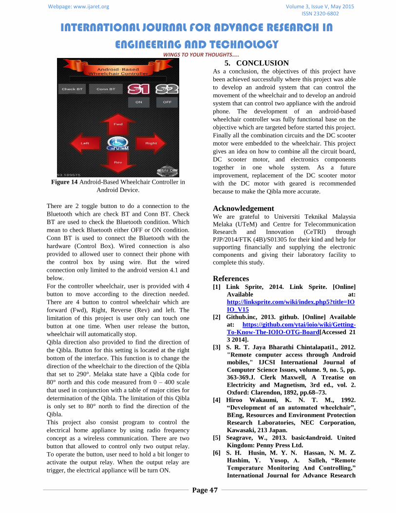
applications for the android platform. Figure 14 shown
the interface of the application for android-based
wheelchair controller.
Webpage: www.ijaret.org Volume 3, Issue V, May 2015 ISSN 2320-6802
INTERNATIONAL JOURNAL FOR ADVANCE RESEARCH IN
ENGINEERING AND TECHNOLOGY WINGS TO YOUR THOUGHTS…..
Page 47
Figure 14 Android-Based Wheelchair Controller in
Android Device.
There are 2 toggle button to do a connection to the
Bluetooth which are check BT and Conn BT. Check
BT are used to check the Bluetooth condition. Which
mean to check Bluetooth either OFF or ON condition.
Conn BT is used to connect the Bluetooth with the
hardware (Control Box). Wired connection is also
provided to allowed user to connect their phone with
the control box by using wire. But the wired
connection only limited to the android version 4.1 and
below.
For the controller wheelchair, user is provided with 4
button to move according to the direction needed.
There are 4 button to control wheelchair which are
forward (Fwd), Right, Reverse (Rev) and left. The
limitation of this project is user only can touch one
button at one time. When user release the button,
wheelchair will automatically stop.
Qibla direction also provided to find the direction of
the Qibla. Button for this setting is located at the right
bottom of the interface. This function is to change the
direction of the wheelchair to the direction of the Qibla
that set to 290°. Melaka state have a Qibla code for
80° north and this code measured from 0 – 400 scale
that used in conjunction with a table of major cities for
determination of the Qibla. The limitation of this Qibla
is only set to 80° north to find the direction of the
Qibla.
This project also consist program to control the
electrical home appliance by using radio frequency
concept as a wireless communication. There are two
button that allowed to control only two output relay.
To operate the button, user need to hold a bit longer to
activate the output relay. When the output relay are
trigger, the electrical appliance will be turn ON.
5. CONCLUSION As a conclusion, the objectives of this project have
been achieved successfully where this project was able
to develop an android system that can control the
movement of the wheelchair and to develop an android
system that can control two appliance with the android
phone. The development of an android-based
wheelchair controller was fully functional base on the
objective which are targeted before started this project.
Finally all the combination circuits and the DC scooter
motor were embedded to the wheelchair. This project
gives an idea on how to combine all the circuit board,
DC scooter motor, and electronics components
together in one whole system. As a future
improvement, replacement of the DC scooter motor
with the DC motor with geared is recommended
because to make the Qibla more accurate.
Acknowledgement We are grateful to Universiti Teknikal Malaysia
Melaka (UTeM) and Centre for Telecommunication
Research and Innovation (CeTRI) through
PJP/2014/FTK (4B)/S01305 for their kind and help for
supporting financially and supplying the electronic
components and giving their laboratory facility to
complete this study.
References [1] Link Sprite, 2014. Link Sprite. [Online]
Available at:
http://linksprite.com/wiki/index.php5?title=IO
IO_V15
[2] Github.inc, 2013. github. [Online] Available
at: https://github.com/ytai/ioio/wiki/Getting-
To-Know-The-IOIO-OTG-Board[Accessed 21
3 2014].
[3] S. R. T. Jaya Bharathi Chintalapati1., 2012.
"Remote computer access through Android
mobiles," IJCSI International Journal of
Computer Science Issues, volume. 9, no. 5, pp.
363-369.J. Clerk Maxwell, A Treatise on
Electricity and Magnetism, 3rd ed., vol. 2.
Oxford: Clarendon, 1892, pp.68–73.
[4] Hiroo Wakaumi, K. N. T. M., 1992.
“Development of an automated wheelchair”,
BEng, Resources and Environment Protection
Research Laboratories, NEC Corporation,
Kawasaki, 213 Japan.
[5] Seagrave, W., 2013. basic4android. United
Kingdom: Penny Press Ltd.
[6] S. H. Husin, M. Y. N. Hassan, N. M. Z.
Hashim, Y. Yusop, A. Salleh, “Remote
Temperature Monitoring And Controlling,”
International Journal for Advance Research

Webpage: www.ijaret.org Volume 3, Issue V, May 2015 ISSN 2320-6802
INTERNATIONAL JOURNAL FOR ADVANCE RESEARCH IN
ENGINEERING AND TECHNOLOGY WINGS TO YOUR THOUGHTS…..
Page 48
in Engineering and Technology, vol. 1, no. 8,
pp. 40-47, 2013.
[7] N. M. Z. Hashim, M. H. A. Halim, H. Bakri,
S. H. Husin, M. M. Said, “Vehicle Security
System Using Zigbee,” International Journal
of Scientific and Research Publications, vol. 3,
no. 9, pp. 03-09, 2013.
[8] S. H. Husin, A. A. Ngahdiman, N. M. Z.
Hashim, Y. Yusop, A. S. Ja’afar, “Home
Electrical Appliances Smart System,”
International Journal of Computer Science
and Mobile Computing, vol. 2, no. 9, pp. 85-
91, 2013.
[9] K. A. A. Aziz, N. Mohamood, M. N. Z.
Hashim, “Sliding Window for Radial Basis
Function Neural Network Face Detection,”
International Journal of Science and
Engineering Applications, vol. 3, no. 2, pp. 94-
97, 2014.
[10] K. A. A. Aziz, R. A. Ramlee, N. M. Z.
Hashim, R. A. Rahman, “Machine Vision
Based Height Measuring System,”
International Journal of Research in Advent
Technology, vol. 2, no. 8, pp. 48-50, 2014.
[11] M. H. A. Ilmudin, N. M. Z. Hashim, A. S.
Ja’afar, A Salleh, A Jaafar, MFM Sam,
“Traffic Light Control System using 434 MHz
Radio Frequency,” International Journal of
Research in Advent Technology, vol. 2, no. 8,
pp. 26-31, 2014.
[12] N. M. Z. Hashim, H. H. Basri, A. Jaafar, M.
Z. A. A. Aziz, A. Salleh, A. S. Ja'afar, “Child
In Car Alarm System Using Various Sensors,”
Journal of Engineering & Applied Sciences,
vol. 9, no. 9, pp. 1653-1658, 2014.
[13] N. M. Z. Hashim, M. R. Anuar, A. Jaafar,
M. Z. A. A. Aziz, A. Salleh, A. S. Ja'afar,
“Graphical User Interface For Wireless
Patient Monitoring System Using Zigbee
Communication,” Journal of Engineering &
Applied Sciences, vol. 9, no. 9, pp. 1554-1558,
2014.
[14] S. A. W. A. S. Mokhtar, N. M. Z. Hashim, N.
R. Mohamad, A. Jaafar, A. Salleh, “Vehicle
Security System Using ZigBee Technology,”
International Journal For Advance Research
In Engineering And Technology, vol. 2, no. 7,
pp. 81-85, 2014.
[15] A. Salleh, N. M. Z. Hashim, N. R. Mohamad,
N. A. A. Hadi, M. Z. A. Ab Aziz,
“Development of High Performance and Low
Cost Automatic Toll Payment System using
RFID Technology for Malaysia
Environment,” International Journal For
Advance Research In Engineering And
Technology, vol. 2, no. 10, pp. 01-07, 2014.