winsps programming according to iec 61131-3 … rexroth/tecnologie e prodotti... · programming...
TRANSCRIPT

Programming according to IEC 61131-3Software Manual
WinSPS
104Edition
Antriebs- und Steuerungstechnik

WinSPS
Programming according to IEC 61131-3Software Manual1070 072 305-104 (03.03) GB
E 2001 – 2003
by Bosch Rexroth AG, Erbach / GermanyAll rights reserved, including applications for protective rights.
Reproduction or distribution by any means subject to our prior written permission.
Discretionary charge 18.–

Contents V
1070 072 305-104 (03.03) GB
Contents
Page
1 Safety Instructions 1–1. . . . . . . . . . . . . . . . . . . . . . . . . . . . 1.1 Intended use 1–1. . . . . . . . . . . . . . . . . . . . . . . . . . . . . . . . . . . . . . . . . . . 1.2 Qualified personnel 1–2. . . . . . . . . . . . . . . . . . . . . . . . . . . . . . . . . . . . . . 1.3 Safety markings on components 1–3. . . . . . . . . . . . . . . . . . . . . . . . . . 1.4 Safety instructions in this manual 1–4. . . . . . . . . . . . . . . . . . . . . . . . . . 1.5 Safety instructions for the described product 1–5. . . . . . . . . . . . . . . . 1.6 Documentation, software release and trademarks 1–6. . . . . . . . . . .
2 Quick start and input examples 2–1. . . . . . . . . . . . . . . . 2.1 Project Default settings 2–1. . . . . . . . . . . . . . . . . . . . . . . . . . . . . . . . . . 2.2 Programming variations 2–2. . . . . . . . . . . . . . . . . . . . . . . . . . . . . . . . . . 2.3 Edit IEC file 2–3. . . . . . . . . . . . . . . . . . . . . . . . . . . . . . . . . . . . . . . . . . . . 2.4 Check symbol file 2–6. . . . . . . . . . . . . . . . . . . . . . . . . . . . . . . . . . . . . . . 2.5 Load program in the controller 2–7. . . . . . . . . . . . . . . . . . . . . . . . . . . . 2.6 Observe and test the program on the monitor 2–8. . . . . . . . . . . . . . .
3 Introduction 3–1. . . . . . . . . . . . . . . . . . . . . . . . . . . . . . . . . . 3.1 What is IEC 61131-3? 3–1. . . . . . . . . . . . . . . . . . . . . . . . . . . . . . . . . . . 3.2 Programming languages of the IEC 61131-3 3–1. . . . . . . . . . . . . . . . 3.2.1 The programming language IL 3–2. . . . . . . . . . . . . . . . . . . . . . . . . . . . 3.2.2 The programming language ST 3–3. . . . . . . . . . . . . . . . . . . . . . . . . . . 3.3 Why use programming languages as per IEC 61131-3 ? 3–3. . . . . 3.4 Difference from “classical” programming languages 3–3. . . . . . . . . . 3.5 Model of the programming as per IEC 61131-3 3–5. . . . . . . . . . . . . . 3.6 Compatibility and fulfillment of standard 3–8. . . . . . . . . . . . . . . . . . . . 3.7 Programming system and controller 3–8. . . . . . . . . . . . . . . . . . . . . . .
4 Project preparations 4–1. . . . . . . . . . . . . . . . . . . . . . . . . . 4.1 Installation 4–1. . . . . . . . . . . . . . . . . . . . . . . . . . . . . . . . . . . . . . . . . . . . . 4.2 Default settings 4–1. . . . . . . . . . . . . . . . . . . . . . . . . . . . . . . . . . . . . . . . . 4.2.1 Licensing the programming languages 4–1. . . . . . . . . . . . . . . . . . . . . 4.2.2 Project default settings 4–2. . . . . . . . . . . . . . . . . . . . . . . . . . . . . . . . . . .
5 Writing programs in the WinSPS Editor 5–1. . . . . . . . . 5.1 Declaration tables 5–3. . . . . . . . . . . . . . . . . . . . . . . . . . . . . . . . . . . . . . . 5.1.1 POU type 5–3. . . . . . . . . . . . . . . . . . . . . . . . . . . . . . . . . . . . . . . . . . . . . . 5.1.2 Variable declaration 5–4. . . . . . . . . . . . . . . . . . . . . . . . . . . . . . . . . . . . . 5.1.3 Type definition 5–8. . . . . . . . . . . . . . . . . . . . . . . . . . . . . . . . . . . . . . . . . . 5.2 Instructions part 5–11. . . . . . . . . . . . . . . . . . . . . . . . . . . . . . . . . . . . . . . . . 5.3 Error messages 5–12. . . . . . . . . . . . . . . . . . . . . . . . . . . . . . . . . . . . . . . . . 5.4 Global variable declaration – variable editor 5–13. . . . . . . . . . . . . . . . 5.5 Global type definition – type editor 5–14. . . . . . . . . . . . . . . . . . . . . . . . . 5.5.1 TYPE: Data Type 5–14. . . . . . . . . . . . . . . . . . . . . . . . . . . . . . . . . . . . . . . 5.5.2 STRUCT: Data structure 5–15. . . . . . . . . . . . . . . . . . . . . . . . . . . . . . . . . 5.5.3 ENUM: Enumeration 5–16. . . . . . . . . . . . . . . . . . . . . . . . . . . . . . . . . . . . . 5.6 Constant definition – DEFINE Editor 5–18. . . . . . . . . . . . . . . . . . . . . . .

ContentsVI
1070 072 305-104 (03.03) GB
6 Program Structure 6–1. . . . . . . . . . . . . . . . . . . . . . . . . . . . 6.1 Program Organization Units– modules of the IEC 6–1. . . . . . . . . . . 6.2 POU types 6–3. . . . . . . . . . . . . . . . . . . . . . . . . . . . . . . . . . . . . . . . . . . . . 6.2.1 Main program – PROGRAM 6–4. . . . . . . . . . . . . . . . . . . . . . . . . . . . . . 6.2.2 Function block – FUNCTION_BLOCK 6–5. . . . . . . . . . . . . . . . . . . . . . 6.2.3 Function – FUNCTION 6–7. . . . . . . . . . . . . . . . . . . . . . . . . . . . . . . . . . . 6.3 Declaration part 6–8. . . . . . . . . . . . . . . . . . . . . . . . . . . . . . . . . . . . . . . . . 6.3.1 Variable types 6–9. . . . . . . . . . . . . . . . . . . . . . . . . . . . . . . . . . . . . . . . . . 6.3.2 Applicability and access options of the variable types 6–11. . . . . . . . 6.4 Instructions part 6–12. . . . . . . . . . . . . . . . . . . . . . . . . . . . . . . . . . . . . . . . . 6.5 Calls between POUs 6–12. . . . . . . . . . . . . . . . . . . . . . . . . . . . . . . . . . . . 6.5.1 Call hierarchy 6–12. . . . . . . . . . . . . . . . . . . . . . . . . . . . . . . . . . . . . . . . . . . 6.5.2 Recursive calls 6–13. . . . . . . . . . . . . . . . . . . . . . . . . . . . . . . . . . . . . . . . . 6.5.3 Call interface – parameters during the call 6–14. . . . . . . . . . . . . . . . . . 6.5.4 Calling up the function blocks 6–17. . . . . . . . . . . . . . . . . . . . . . . . . . . . . 6.5.5 Calling up the functions 6–19. . . . . . . . . . . . . . . . . . . . . . . . . . . . . . . . . . 6.6 Instance building of function blocks 6–21. . . . . . . . . . . . . . . . . . . . . . . . 6.6.1 Validity of function blocks 6–22. . . . . . . . . . . . . . . . . . . . . . . . . . . . . . . . . 6.6.2 Module with “memory” 6–22. . . . . . . . . . . . . . . . . . . . . . . . . . . . . . . . . . . 6.6.3 Instance building for combination with “classical” programming languages
6–22
7 Data model 7–1. . . . . . . . . . . . . . . . . . . . . . . . . . . . . . . . . . . 7.1 Language elements 7–1. . . . . . . . . . . . . . . . . . . . . . . . . . . . . . . . . . . . . 7.1.1 Key words 7–2. . . . . . . . . . . . . . . . . . . . . . . . . . . . . . . . . . . . . . . . . . . . . . 7.1.2 Identifiers 7–3. . . . . . . . . . . . . . . . . . . . . . . . . . . . . . . . . . . . . . . . . . . . . . 7.1.3 Literals 7–4. . . . . . . . . . . . . . . . . . . . . . . . . . . . . . . . . . . . . . . . . . . . . . . . 7.1.4 Delimiter 7–7. . . . . . . . . . . . . . . . . . . . . . . . . . . . . . . . . . . . . . . . . . . . . . . 7.1.5 Comments 7–8. . . . . . . . . . . . . . . . . . . . . . . . . . . . . . . . . . . . . . . . . . . . . 7.2 Data types 7–9. . . . . . . . . . . . . . . . . . . . . . . . . . . . . . . . . . . . . . . . . . . . . 7.2.1 Elementary data types 7–9. . . . . . . . . . . . . . . . . . . . . . . . . . . . . . . . . . . 7.2.2 Derived data types (Type definition) 7–11. . . . . . . . . . . . . . . . . . . . . . . 7.2.3 Generic data types 7–13. . . . . . . . . . . . . . . . . . . . . . . . . . . . . . . . . . . . . . 7.3 Variables 7–15. . . . . . . . . . . . . . . . . . . . . . . . . . . . . . . . . . . . . . . . . . . . . . . 7.3.1 Declaration of variables 7–15. . . . . . . . . . . . . . . . . . . . . . . . . . . . . . . . . . 7.3.2 Initialization of variables and remanence 7–16. . . . . . . . . . . . . . . . . . . 7.3.3 Access to variables 7–18. . . . . . . . . . . . . . . . . . . . . . . . . . . . . . . . . . . . . . 7.3.4 Physical addresses 7–19. . . . . . . . . . . . . . . . . . . . . . . . . . . . . . . . . . . . . . 7.3.5 String variables 7–21. . . . . . . . . . . . . . . . . . . . . . . . . . . . . . . . . . . . . . . . . 7.3.6 ARRAY 7–22. . . . . . . . . . . . . . . . . . . . . . . . . . . . . . . . . . . . . . . . . . . . . . . . 7.3.7 Data structures (STRUCT) 7–28. . . . . . . . . . . . . . . . . . . . . . . . . . . . . . . 7.3.8 Variable attributes 7–30. . . . . . . . . . . . . . . . . . . . . . . . . . . . . . . . . . . . . . .

Contents VII
1070 072 305-104 (03.03) GB
8 Programming language Instruction List (IL) 8–1. . . . . 8.1 Instructions 8–1. . . . . . . . . . . . . . . . . . . . . . . . . . . . . . . . . . . . . . . . . . . . . 8.2 Working register and status bits 8–2. . . . . . . . . . . . . . . . . . . . . . . . . . . 8.3 Current Result (CR) – the universal accumulator 8–2. . . . . . . . . . . . 8.4 Program rules 8–4. . . . . . . . . . . . . . . . . . . . . . . . . . . . . . . . . . . . . . . . . . 8.4.1 IL sequences 8–4. . . . . . . . . . . . . . . . . . . . . . . . . . . . . . . . . . . . . . . . . . . 8.4.2 Label 8–5. . . . . . . . . . . . . . . . . . . . . . . . . . . . . . . . . . . . . . . . . . . . . . . . . . 8.4.3 Nesting levels, Parenthesis 8–5. . . . . . . . . . . . . . . . . . . . . . . . . . . . . . . 8.5 Instruction set 8–7. . . . . . . . . . . . . . . . . . . . . . . . . . . . . . . . . . . . . . . . . . 8.5.1 Load instructions – LD 8–9. . . . . . . . . . . . . . . . . . . . . . . . . . . . . . . . . . . 8.5.2 Assignments – ST, S, R 8–10. . . . . . . . . . . . . . . . . . . . . . . . . . . . . . . . . . 8.5.3 Boolean operators AND, &, OR, XOR 8–12. . . . . . . . . . . . . . . . . . . . . . 8.5.4 Arithmetic operators ADD, SUB, MUL, DIV 8–15. . . . . . . . . . . . . . . . . 8.5.5 Comparison operators– GT, GE, EQ, LE, LT, NE 8–18. . . . . . . . . . . . 8.5.6 Jump operators – JMP, JMPC, JMPCN 8–19. . . . . . . . . . . . . . . . . . . . 8.5.7 Call of function blocks – CAL, CALC, CALCN 8–20. . . . . . . . . . . . . . . 8.5.8 Call of functions 8–22. . . . . . . . . . . . . . . . . . . . . . . . . . . . . . . . . . . . . . . . . 8.5.9 Return jump – RET, RETC, RETCN 8–23. . . . . . . . . . . . . . . . . . . . . . .
9 Programming language Structured Text (ST) 9–1. . . . 9.1 Expressions, operands and operators 9–1. . . . . . . . . . . . . . . . . . . . . . 9.2 Instructions 9–3. . . . . . . . . . . . . . . . . . . . . . . . . . . . . . . . . . . . . . . . . . . . . 9.2.1 Assignment 9–4. . . . . . . . . . . . . . . . . . . . . . . . . . . . . . . . . . . . . . . . . . . . 9.2.2 Call of an function block 9–4. . . . . . . . . . . . . . . . . . . . . . . . . . . . . . . . . . 9.2.3 Return jump – RETURN 9–5. . . . . . . . . . . . . . . . . . . . . . . . . . . . . . . . . 9.2.4 Conditional execution 9–5. . . . . . . . . . . . . . . . . . . . . . . . . . . . . . . . . . . . 9.2.5 Selection, – IF 9–6. . . . . . . . . . . . . . . . . . . . . . . . . . . . . . . . . . . . . . . . . . 9.2.6 Multi-selection– CASE 9–7. . . . . . . . . . . . . . . . . . . . . . . . . . . . . . . . . . . 9.2.7 FOR loop 9–8. . . . . . . . . . . . . . . . . . . . . . . . . . . . . . . . . . . . . . . . . . . . . . 9.2.8 WHILE loop 9–10. . . . . . . . . . . . . . . . . . . . . . . . . . . . . . . . . . . . . . . . . . . . 9.2.9 REPEAT loop 9–10. . . . . . . . . . . . . . . . . . . . . . . . . . . . . . . . . . . . . . . . . . . 9.2.10 Deflecting and non-deflecting loops 9–11. . . . . . . . . . . . . . . . . . . . . . . . 9.2.11 Premature loop end – EXIT 9–12. . . . . . . . . . . . . . . . . . . . . . . . . . . . . . .
10 Check load and test program 10–1. . . . . . . . . . . . . . . . . . 10.1 Check / compile module 10–1. . . . . . . . . . . . . . . . . . . . . . . . . . . . . . . . . . 10.2 Link all modules – Create new project 10–2. . . . . . . . . . . . . . . . . . . . . 10.3 Project specifications in the symbol file 10–4. . . . . . . . . . . . . . . . . . . . . 10.4 Load program and modules 10–5. . . . . . . . . . . . . . . . . . . . . . . . . . . . . . 10.5 Monitor 10–6. . . . . . . . . . . . . . . . . . . . . . . . . . . . . . . . . . . . . . . . . . . . . . . .
11 Use of IEC modules in the classical programming lan-guages 11–1. . . . . . . . . . . . . . . . . . . . . . . . . . . . . . . . . . . . . . .
11.1 Pure IEC programs 11–1. . . . . . . . . . . . . . . . . . . . . . . . . . . . . . . . . . . . . . 11.2 Mixed programs 11–2. . . . . . . . . . . . . . . . . . . . . . . . . . . . . . . . . . . . . . . . . 11.3 Function block call 11–4. . . . . . . . . . . . . . . . . . . . . . . . . . . . . . . . . . . . . . 11.3.1 Call parameter list – wizard for FB call 11–5. . . . . . . . . . . . . . . . . . . . . 11.3.2 Changing the FB calls 11–8. . . . . . . . . . . . . . . . . . . . . . . . . . . . . . . . . . . 11.3.3 Deleting the FB calls 11–9. . . . . . . . . . . . . . . . . . . . . . . . . . . . . . . . . . . . . 11.3.4 Call in the Sequential Function Chart 11–10. . . . . . . . . . . . . . . . . . . . . . 11.4 Symbol file – interface of mixed programming 11–11. . . . . . . . . . . . . . . 11.4.1 Physical addresses and miscellaneous data 11–11. . . . . . . . . . . . . . . . 11.4.2 Symbolic operands via the call interface 11–13. . . . . . . . . . . . . . . . . . . . 11.4.3 Symbolic operands as global variables 11–14. . . . . . . . . . . . . . . . . . . . . 11.4.4 Global type definitions 11–14. . . . . . . . . . . . . . . . . . . . . . . . . . . . . . . . . . . 11.5 Differences in case of mixed programming 11–17. . . . . . . . . . . . . . . . .
ContentsVIII
1070 072 305-104 (03.03) GB
12 Standardized functionality 12–1. . . . . . . . . . . . . . . . . . . . . 12.1 Standard functions 12–1. . . . . . . . . . . . . . . . . . . . . . . . . . . . . . . . . . . . . . 12.1.1 Generic data types and “overloaded” functions 12–1. . . . . . . . . . . . . . 12.1.2 Extensibility of functions 12–3. . . . . . . . . . . . . . . . . . . . . . . . . . . . . . . . . . 12.1.3 Type conversion 12–3. . . . . . . . . . . . . . . . . . . . . . . . . . . . . . . . . . . . . . . . 12.1.4 Numeric functions 12–5. . . . . . . . . . . . . . . . . . . . . . . . . . . . . . . . . . . . . . . 12.1.5 Arithmetic functions 12–5. . . . . . . . . . . . . . . . . . . . . . . . . . . . . . . . . . . . . 12.1.6 Shift functions 12–7. . . . . . . . . . . . . . . . . . . . . . . . . . . . . . . . . . . . . . . . . . 12.1.7 Boolean functions – logical links 12–8. . . . . . . . . . . . . . . . . . . . . . . . . . . 12.1.8 Selection 12–8. . . . . . . . . . . . . . . . . . . . . . . . . . . . . . . . . . . . . . . . . . . . . . . 12.1.9 Comparison 12–9. . . . . . . . . . . . . . . . . . . . . . . . . . . . . . . . . . . . . . . . . . . . 12.1.10 Functions for strings 12–10. . . . . . . . . . . . . . . . . . . . . . . . . . . . . . . . . . . . . 12.2 Standard function block 12–12. . . . . . . . . . . . . . . . . . . . . . . . . . . . . . . . . . 12.2.1 Bistable elements – Flipflops 12–14. . . . . . . . . . . . . . . . . . . . . . . . . . . . . 12.2.2 Edge detection 12–15. . . . . . . . . . . . . . . . . . . . . . . . . . . . . . . . . . . . . . . . . . 12.2.3 Counter 12–16. . . . . . . . . . . . . . . . . . . . . . . . . . . . . . . . . . . . . . . . . . . . . . . . 12.2.4 Timer 12–18. . . . . . . . . . . . . . . . . . . . . . . . . . . . . . . . . . . . . . . . . . . . . . . . . .
13 Standard fulfilment 13–1. . . . . . . . . . . . . . . . . . . . . . . . . . . 13.1 Common elements 13–1. . . . . . . . . . . . . . . . . . . . . . . . . . . . . . . . . . . . . . 13.2 Language elements 13–14. . . . . . . . . . . . . . . . . . . . . . . . . . . . . . . . . . . . . 13.3 Causes of errors 13–16. . . . . . . . . . . . . . . . . . . . . . . . . . . . . . . . . . . . . . . .
A Annex A–1. . . . . . . . . . . . . . . . . . . . . . . . . . . . . . . . . . . . . . . . A.1 Abbreviations A–1. . . . . . . . . . . . . . . . . . . . . . . . . . . . . . . . . . . . . . . . . . . A.2 Index A–2. . . . . . . . . . . . . . . . . . . . . . . . . . . . . . . . . . . . . . . . . . . . . . . . . .

Safety Instructions 1–1
1070 072 305-104 (03.03) GB
1 Safety Instructions
Before you start programming the software PLC PCL or the CL550 by usingprogramming languages according to IEC 61131-3, we recommend that youthoroughly familiarize yourself with the contents of this manual. Keep thismanual in a place where it is always accessible to all users.
1.1 Intended use
This manual contains information required for the proper use of this product.The products described hereunder have been developed, manufactured,tested and documented in compliance with the safety standards. Theseproducts pose no danger to persons or property if they are used inaccordance with the handling stipulations and safety notes prescribed fortheir configuration, mounting, and proper operation.

Safety Instructions1–2
1070 072 305-104 (03.03) GB
1.2 Qualified personnel
This instruction manual is designed for specially trained personnel. The rele-vant requirements are based on the job specifications as outlined by theZVEI and VDMA professional associations in Germany. Please refer to thefollowing German-Language publication:Weiterbildung in der AutomatisierungstechnikPublishers: ZVEI and VDMA Maschinenbau VerlagPostfach 71 08 6460498 Frankfurt/Germany
This instruction manual is specifically designed for PLC technicians. Basicskills in Programmable Logic Controllers are an advantage, however, theyare not mandatory.
Interventions in the hardware and software of our products not described inthis instruction manual may only be performed by our skilled personnel.
Unqualified interventions in the hardware or software or non-compliancewith the warnings listed in this instruction manual or indicated on the productmay result in serious personal injury or damage to property.
Installation and maintenance of the products described hereunder is theexclusive domain of trained electricians as per IEV 826-09-01 (modified)who are familiar with the contents of this manual.
Trained electricians are persons of whom the following is true:D They are capable, due to their professional training, skills and expertise,
and based upon their knowledge of and familiarity with applicable techni-cal standards, of assessing the work to be carried out, and of recognizingpossible dangers.
D They possess, subsequent to several years’ experience in a comparablefield of endeavour, a level of knowledge and skills that may be deemedcommensurate with that attainable in the course of a formal professionaleducation.
With regard to the foregoing, please read the information about our compre-hensive training program. The professional staff at our training centre will bepleased to provide detailed information. You may contact the centre by tele-phone at (+49) 6062 78-258.

Safety Instructions 1–3
1070 072 305-104 (03.03) GB
1.3 Safety markings on components
DANGER! High voltage!
DANGER! Corrosive battery acid!
DANGER! Hazardous light emissions (optical fibre cable emitters)!
Disconnect mains power before opening!
Lug for connecting PE conductor only!
Functional earthing or low-noise earth only!
Screened conductor only!

Safety Instructions1–4
1070 072 305-104 (03.03) GB
1.4 Safety instructions in this manual
DANGERThis symbol is used wherever insufficient or lacking observance of thisinstruction can result in personal injury.
CAUTIONThis symbol is used wherever insufficient or lacking observance ofinstructions can result in damage to equipment or data files.
. This symbol is used to alert the user to an item of special interest.

Safety Instructions 1–5
1070 072 305-104 (03.03) GB
1.5 Safety instructions for the described product
DANGERFatal injury hazard through ineffective Emergency-STOP devices!Emergency-STOP safety devices must remain effective andaccessible during all operating modes of the system. The release offunctional locks imposed by Emergency-STOP devices must neverbe allowed to cause an uncontrolled system restart! Before restoringpower to the system, test the Emergency-STOP sequence!
DANGERDanger to persons and equipment!Test every new program before operating the system!
DANGERRetrofits or modifications may interfere with the safety of theproducts described hereunder!The consequences may be severe personal injury or damage toequipment or the environment. Therefore, any system retrofitting ormodification utilizing equipment components from othermanufacturers will require express approval by Bosch.

Safety Instructions1–6
1070 072 305-104 (03.03) GB
1.6 Documentation, software release and trademarks
Relevant documentationThe present manual provides the user with comprehensive information ab-out programming the
D PCL (Software PLC)D CL550
according to IEC 61131-3.
. All informations about PCL are also valid for the integrated controllersiPCL and PCLrho4.0, even if they are not mentioned in this manual.
Overview of available manuals:
Manuals Language Order no.
PCL and CL550, Programming and Operation,Software Manual
english 1070 072 189
iPCL, System Description an Programming Ma-nual
english 1070 073 875
. In this manual the floppy disk drive always uses drive letter A:, and thehard disk drive always uses drive letter C:.
Special keys or key combinations are shown enclosed in pointed brackets:D Named keys: e.g., <Enter>, <PgUp>, <Del>D Key combinations (pressed simultaneously): e.g., <Ctrl> + <PgUp>
Release
. The descriptive information contained in this manual applies to:
Software: WinSPS Version 3.1 and laterFirmware: PCL Version 2.3 and later
CL550 Version 1.4 and lateriPCL NC software version 7.3 and laterPCLrho4.0 Version VO04L and later
TrademarksAll trademarks referring to software that is installed on Bosch products whenshipped from the factory represent the property of their respective owners.
At the time of shipment from the factory, all installed software is protected bycopyright. Software may therefore be duplicated only with the prior permis-sion of the respective manufacturer or copyright owner.
MS-DOSr and Windowst are registered trademarks of Microsoft Corpo-ration.

Quick start and input examples 2–1
1070 072 305-104 (03.03) GB
2 Quick start and input examples
Various working steps should be explained
D Project default settingsD Edit IEC fileD Check symbol fileD Load program into the controllerD Observe and test the program on the monitor
using a simple example.
Additional detailed input examples can be found in the help of WinSPS Soft-ware, section “Introduction to WinSPS”.
2.1 Project Default settings
In the project default settings of the WinSPS, files and access paths are spe-cified. For the IEC programming, a separate license is required. The licen-sing is likewise called up in the default settings window, also refer to section4.
The following illustration shows which input fields are important for the edi-ting of IEC programs:
D Controller: Only controller of the type PCL, iPCL, PCLrho4.0 or CL550can be used.
D Symbol file: In the symbol file, various inputs of WinSPS are managedautomatically.
D IEC file (IL/ST): For the editing of IEC files, a filename must be entered inthis input field.The programming language is identified through the file extension :Instruction List (IL): “.IL”Structured Text (ST): “.ST”The file extension must be entered by the user.
Start the editor for entering the program by pressing the appropriate button.

Quick start and input examples2–2
1070 072 305-104 (03.03) GB
Project default settings
2.2 Programming variations
The WinSPS allows you to use two variations of the IEC programming. De-tailed information and examples concerning this can be found in section 11:
1) Combination of IEC modules and “classical programming languages”2) IEC program without classical parts
The first variation is particularly useful when you want to program specificfunctions using IEC modules, however, other control functions are program-med e.g. in the classical programming language Bosch-IL. In this case, theIEC modules are called up from the IL, but not vice versa.
In case of the second variation on the other hand, only IEC instructions areallowed. This is then meaningful when only the programming languages ofthe IEC 61131-3 are to used in a control program.
The following program example shows two variations without classicalparts. The first variation is shown in section 11.
Quick start and input examples 2–3
1070 072 305-104 (03.03) GB
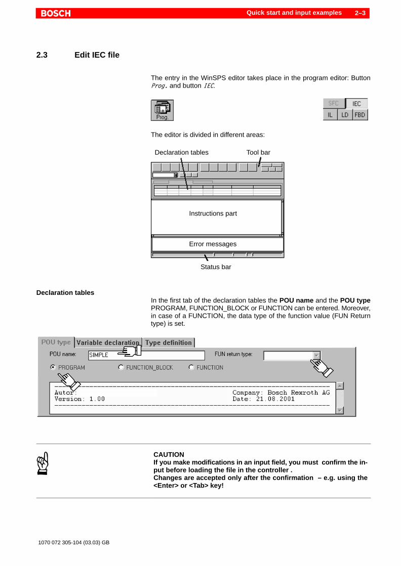
2.3 Edit IEC file
The entry in the WinSPS editor takes place in the program editor: ButtonProg. and button IEC.
The editor is divided in different areas:
Declaration tables Tool bar
Instructions part
Status bar
Error messages
Declaration tablesIn the first tab of the declaration tables the POU name and the POU typePROGRAM, FUNCTION_BLOCK or FUNCTION can be entered. Moreover,in case of a FUNCTION, the data type of the function value (FUN Returntype) is set.
CAUTIONIf you make modifications in an input field, you must confirm the in-put before loading the file in the controller .Changes are accepted only after the confirmation – e.g. using the<Enter> or <Tab> key!
Quick start and input examples2–4
1070 072 305-104 (03.03) GB
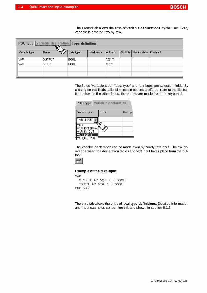
The second tab allows the entry of variable declarations by the user. Everyvariable is entered row by row.
The fields “variable type”, “data type” and “attribute” are selection fields. Byclicking on this fields, a list of selection options is offered, refer to the illustra-tion below. In the other fields, the entries are made from the keyboard.
The variable declaration can be made even by purely text input. The switch-over between the declaration tables and text input takes place from the but-ton:
Example of the text input:VAR OUTPUT AT %Q1.7 : BOOL; INPUT AT %I0.3 : BOOL;END_VAR
The third tab allows the entry of local type definitions. Detailed informationand input examples concerning this are shown in section 5.1.3.

Quick start and input examples 2–5
1070 072 305-104 (03.03) GB
Instructions partInstructions of the programming language IL or ST, can be entered directly inthe instructions part, refer to the examples:
Instructions in the programming language IL
Instruction in the programming language ST

Quick start and input examples2–6
1070 072 305-104 (03.03) GB
2.4 Check symbol file
On editing and completion of the IEC files,
1. every single IEC file (POU) is compiled i.e. translated into program code2. all files of the control project are combined into an integrated program
(link, Create new project)3. the integrated program is loaded in the controller.
The working steps can be called up individually or jointly from the menu func-tion controller " load. Detailed information concerning this can be foundin section 10.
The symbol file should be checked and in necessary, changed so that thesecond step „Create new project“ can be carried out. The symbol file is calledup using the button
.
Normally, WinSPS automatically manages the entries in the symbol file. Anentry must be changed manually if the need be. At the position for “OM1”, themodule for main program (PROGRAM POU) must be entered.
Example:OM1,R SIMPLE ; Cyclic program processing
The example shows the entry of the module “SIMPLE” in the symbol file. Inthe current control folder, the file “Simple.IL” or “Simple.ST” must exist,which must be of the POU type “PROGRAM”.

Quick start and input examples 2–7
1070 072 305-104 (03.03) GB
2.5 Load program in the controller
The menu function controller " Load opens a dialog window. Activate theoption “load integrated program” and start the loading process.
DANGERDo not load the sample program into an active system!
Before loading , WinSPS checks the project to be loaded. Only error freecompiled and linked modules are loaded. If necessary, before loading, thecompiler or linker function for these modules is automatically called up.
Error messages are outputted should errors be detected during compilationor linking. Using the button “Go to”, one can jump to the error position withinthe module.
Project generation during the loading process
Quick start and input examples2–8
1070 072 305-104 (03.03) GB
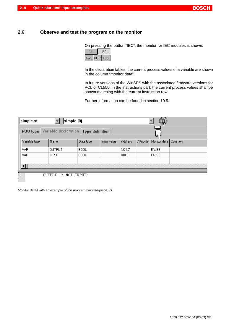
2.6 Observe and test the program on the monitor
On pressing the button “IEC”, the monitor for IEC modules is shown.
In the declaration tables, the current process values of a variable are shownin the column “monitor data”.
In future versions of the WinSPS with the associated firmware versions forPCL or CL550, in the instructions part, the current process values shall beshown matching with the current instruction row.
Further information can be found in section 10.5.
Monitor detail with an example of the programming language ST

Introduction 3–1
1070 072 305-104 (03.03) GB
3 Introduction
3.1 What is IEC 61131-3?
At the beginning of the nineties, the International Electrotechnical Commis-sion (IEC) established the standard IEC 1131. At the end of that decade, thisstandard was renamed as IEC 61131. This standard standardizes – pre-viously manufacturer-dependent – PLC programming. Part 3 (IEC 61131-3)of this international standard contains specifications of the programminglanguages. As German standard DIN IEC 61131-3, it moreover replaces thestandards DIN 19239, DIN 40719T6 and the VDI guidelines VDI 2880 page4.
In order to understand the IEC 61131-3 in greater detail, we recommend thefollowing literature:John, Tiegelkamp: IEC 61131-3: Programming Industrial AutomationSystems, Springer Verlag, Berlin,and the information available in the Internet at PLCopen:www.plcopen.org
3.2 Programming languages of the IEC 61131-3
The languages retained from the ”classical” PLC programming
D Instruction List (IL)D Ladder Diagram (LD)D Function Block Diagram (FBD), as used by Bosch earlier: Function plan
were also included in the standard like the programming languages desi-gned according to the current requirements:
D Sequential Function Chart (SFC)D Structured Text (ST)
To some extent, the different languages allow conversion into each other.They can also be mixed virtually in any way so that within the framework of aproject e.g. an ST module can be called up from a programming step of theSFC.

Introduction3–2
1070 072 305-104 (03.03) GB
ExamplesLD A
Instruction List (IL) ANDN BST C
Ladder Diagram (LD)
Function Block Diagram (FBD)
Sequential Function Chart (SFC)
Structured Text (ST) C := A AND NOT B;
Programming languages of the WinSPSThe programming system WinSPS presently supports the programming lan-guages IL and ST in conformance with the standard IEC 61131-3. The pro-gramming languages LD, FBD and the presentation method SFC are basedon IEC 61131-3 in further sections.
Parallel to the IL as per IEC, programming can also be done in WinSPS in theestablished , “classical” IL. The classical IL is invoked in the editor and moni-tor using the button IL , the Instruction List as per IEC using the button IEC.
. In order to prevent mix-up with the established Bosch programminglanguages, the following language application is made:IEC-IL: Instruction List as per IEC 61131-3.Bosch-IL: Classical Instruction List (based on DIN 19239).
3.2.1 The programming language IL
The Instruction List (IL) as per IEC 61131-3 is a machine-like programminglanguage. Machine-like means that the instructions can be directly conver-ted into the binary machine code of the PLC.
In comparison to the programming language ST, multiple program rows arerequired in IL in order to formulate an instruction.
The programming language IL is described in detail in section 8.

Introduction 3–3
1070 072 305-104 (03.03) GB
3.2.2 The programming language ST
The Structured Text (ST) is a text-like higher programming language. Incomparison to machine-like IL, ST is a programming language, in which ex-tensive language constructs allow a very compact formulation of the pro-gramming task.
An ST program consists of instructions. In an instruction, values are workedout and assigned, modules are called up and exited, and command flow iscontrolled.
ST offers the advantage that an open program structure can be realized. SThas a lesser efficiency – for example, in comparison IL. The programs areslower depending upon the complexity.
The programming language ST is described in detail in section 9.
3.3 Why use programming languages as per IEC 61131-3 ?
A great advantage of the programming languages as per IEC 61131-3 is evi-dent when used for different PLC systems. Reusability and interchangeabi-lity of programs simplifies the portability between various systems.
The user enjoys the advantage of a uniform language and program struc-ture. As a result of this, there is an advantage in terms of savings in the trai-ning of the application programmers.
Due to standardization and certification, program systems can be comparedand evaluated among themselves, refer to section 3.6. The programs can beeasily ported between various systems.
3.4 Difference from “classical” programming languages
D The IEC 61131-3 is an international standard. The syntax of the program-ming language is basically in the English language.
D The IEC 61131-3 specifies type, structure and contents of modules. Itacts the same way with the data to be processed. The standardized dataorganization makes data modules, data arrays and symbol file redun-dant, refer to the illustration below. In this regard, also refer to the section4.2.2.
D IL, LD and FBD are based on the above-mentioned structure and dataadministration. With regard to these points, they are fundamentally diffe-rent from the classical procedures.
D SFC is a presentation method based on the IEC 60848 (French GRAF-CET standard).
D ST is a new language which was realized only with the introduction of IEC61131-3.

Introduction3–4
1070 072 305-104 (03.03) GB
D If in a “classical” program, data is declared globally (in the symbol file),while programming as per IEC 61131-3, there exists the option of defi-ning the data locally also and there, it can be protected against uninten-tional access.
D Input and output parameters also have access protection in case of mo-dule calls.
D Checking of the data formats in case of variables and direct memory ad-dresses of the PLC such as E/A/M. As a result of this, access of data inincorrect format is ruled out.
D Variables – apart from physical addresses – do not have a fixed memoryarea in the PLC. This is automatically assigned by WinSPS during pro-gram set-up .
D The instance building in case of function blocks allows implementation ofmodules “with memory”. This principle is known from classical counterand timer functions. It can however also be used for user function blocksin case of modules as per IEC.
OM
Instructions
FC (PB)
Instructions
DM
Data
Symbol file (data)
Modules and data of the “classical” programming
PROG
Instructions
FB
Instructions
Data
Data
Global data
FUN
Instructions
Data
Modules and data of the programming as per IEC 61131–3

Introduction 3–5
1070 072 305-104 (03.03) GB
3.5 Model of the programming as per IEC 61131-3
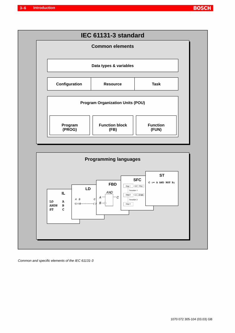
Basis of the IEC is a model which clearly distinguishes commonly usable ele-ments from the individual programming languages, refer to the following illu-stration. As a result of this, many features can be used the same way fordifferent programming languages.
The common elements are handled in detail in sections 6, 7 and 12, the pro-gramming languages are handled in sections 8 and 9.
Introduction3–6
1070 072 305-104 (03.03) GB
IEC 61131-3 standard
Common elements
Data types & variables
Configuration Resource Task
Program Organization Units (POU)
Program(PROG)
Function block(FB)
Function(FUN)
Programming languages
ILLD
FBDSFC
ST
Common and specific elements of the IEC 61131-3

Introduction 3–7
1070 072 305-104 (03.03) GB
Data types and variablesFormat, contents and syntax of data types and variables are fixed by the IECand to a great extent, they are identical for all IEC programming languages.The programming system WinSPS monitors the usage of variables accor-ding to their type, as a result of which program errors are virtually ruled out.
The access to hardware addresses such as inputs, outputs and labels ispossible. However, hardware addresses (physical addresses) must as va-riables be assigned to a data type in advance. With this, even here, theusage of variables according to their type is monitored. Moreover, the decla-ration of hardware addresses is allowed only in a single module . This increa-ses the portability to systems with other hardware features.
Every variable has a standard or user defined initial value. Variables can beassigned the attribute “RETAIN” in order to allow a remanent behavior.
Arrays and data structures allow the implementation of very complex datamodels.
Configuration, Resource, TaskThe IEC plans these elements for runtime characteristics, the assignment ofthe PLC hardware and for communication links between controls.
These elements are presently not supported .
Program Organization UnitsProgram Organization Units (POU) are the modules in the IEC 61131-3.Features and interfaces of the modules are clearly defined. Every modulehas its own data range. As a result, even modules “with memory” can be im-plemented. These modules can be called up repeatedly within a program cy-cle, without mutually affecting each other.
An efficient parameterization of the module interface allows protection of va-riables against unauthorized access, passing or return of defined variablesin a module, passing of pointers to variables and access to global variables.
Typical PLC functionalities such as time, counters or arithmetic functions arestandardized by the IEC as standard functions and function modules. Thesehave clearly defined interfaces and provide established results. They can becalled up from all programming languages.
Programming languagesDepending on the application area, a selection can be made among the fiveprogramming languages. All above-mentioned features of the “common ele-ments” allow their use in any of the five programming languages.
WinSPS presently supports two programming languages: IL and ST.

Introduction3–8
1070 072 305-104 (03.03) GB
3.6 Compatibility and fulfillment of standard
The IEC 61131 is not a mandatory rule book but a guideline, which can befollowed by the manufacturers to greater or lesser degree. The respectivemanufacturer must disclose the degree of implementation . For this, the IECintends a certification, which provides the user exact information concerningthe compatibility and norm fulfillment.
. Pay attention to the norm fulfillment of the WinSPS in section 13.
The Bosch programming system WinSPS has the “Base Level Certificate”for the programming language ST.
3.7 Programming system and controller
Bosch supports programming in compliance with IEC with the programmingsystem WinSPS. A lot of help is available for programming and commissio-ning. The following programming languages conform to IEC 61131-3:
D Instruction ListD Structured Text
Other programming languages in WinSPS are strongly based on the IEC61131-3.
The programming as per IEC is allowed with the controllers listed in section1.6. Kindly pay attention to the instructions concerning the version numbereven there. Due to the constant advancement of programming system andcontroller, attention is to be paid to the appropriate firmware and softwareversions.
The listed controllers are suitable due to their modern and open hardwarearchitecture, specially in view of the specifications of the IEC 61131-3. Withfirmware updates, these controllers can be adapted to the future develop-ments. For this, also pay attention to various instructions concerning presentfunction extensions.
Project preparations 4–1
1070 072 305-104 (03.03) GB
4 Project preparations
The programming tool WinSPS provides an easy-to-use editor for inputtingdata and instructions in various IEC programming languages. The monitorallows program tracking and data observation for commissioning and errordetection. Before calling up the editor or monitor, a few default settings mustbe made.
4.1 Installation
The WinSPS software (order no. 1070 077 925) can be installed on the PCfrom the CD “PLC Tools” or directly from the internet. The internet address is:“www.BoschRexroth.de”. For the installation, kindly pay attention to the ac-companying text files.
4.2 Default settings
The dialog window for default settings appears after the WinSPS software isinvoked. Here, all project and control related settings are made. These areretained even after exiting the program.
The default settings are divided in various functions:
D LicenseD DirectoriesD ProjectsD SettingsD File names and link to the control.
4.2.1 Licensing the programming languages
A separate license is required for programming as per IEC 61131-3. The li-cense is called up in the default settings window. If no valid license for theIEC programming languages exists, such projects cannot be created or pro-cessed.
In the license dialog window, you have the choice between various types oflicenses.
D Soft-license: A license is installed on the hard disk of the programmingunit, without any requirement of additional hardware.
Project preparations4–2
1070 072 305-104 (03.03) GB
D Hardlock license: Instead of a software license, you can use a hardlockfor plugging into the parallel interface or as an internal ISA Bus card (In-troCard). You can get the hardlock from the Bosch Software Service, seecover page for address. A hardlock can simultaneously hold the licenscefor WinSPS, WinCAN, WinDP and WinPanel.
D 14 Days test license: There is an alternate option to install a test licence(= free of cost, 14 days test licence). A test licence can be installed onlyonce on the computer.
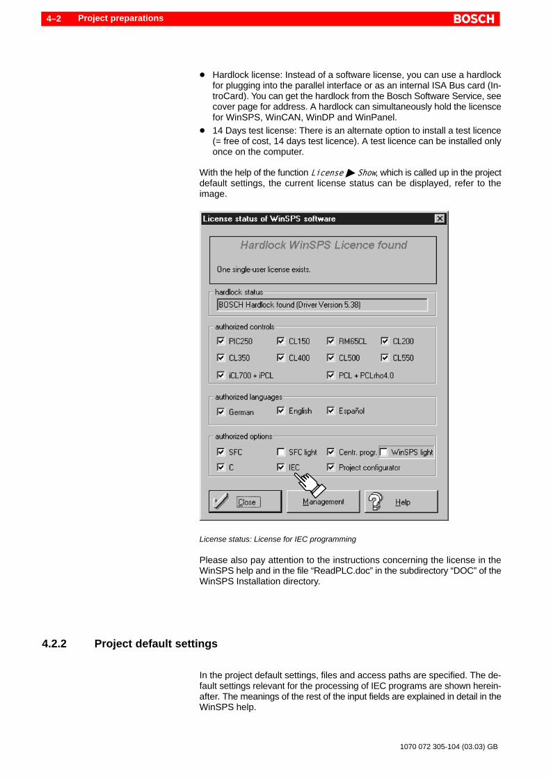
With the help of the function License " Show, which is called up in the projectdefault settings, the current license status can be displayed, refer to theimage.
License status: License for IEC programming
Please also pay attention to the instructions concerning the license in theWinSPS help and in the file “ReadPLC.doc” in the subdirectory “DOC” of theWinSPS Installation directory.
4.2.2 Project default settings
In the project default settings, files and access paths are specified. The de-fault settings relevant for the processing of IEC programs are shown herein-after. The meanings of the rest of the input fields are explained in detail in theWinSPS help.

Project preparations 4–3
1070 072 305-104 (03.03) GB
Example of a project default settings
Program fileThis field can be left empty.
The data concerning the program files is required only when IEC modulesare to be called from “classical programming languages” (e.g. classical IL).This option is discussed in detail in chapter 11.
In case of IEC programming projects, the WinSPS generates automatic pro-gram modules. For these modules, file names are reserved that may not beused for other purposes.
Reserved program files are the file names of the used IEC files with the ex-tension “.IL “ and “.ST”. WinSPS generates new program files with the exten-sion “.PXO”. Similarly, the symbol names of the program modules FC512 toFC1023 are reserved. The numbering is control dependent and can be adju-sted through the symbol file depending upon the application. More informa-tion in this regard can be obtained in chapter 10.3.
Symbol fileThe programming as per IEC 61131-3 does nor foresee any symbol file. Inorder to however allow a mixing of “classical” programming languages withprogramming languages as per IEC, the symbol file is not dispensed withdue to compatibility reasons. The processing of the symbol file is differentia-ted depending upon the structure of the program:
D Combination of an IEC program with classical program parts:All used symbols, as well as program and data modules of the classicalprogramming language must be entered manually in the symbol file. Thisis discussed in detail in chapter 11.4.

Project preparations4–4
1070 072 305-104 (03.03) GB
D Purely IEC programming:The symbol file is managed automatically from WinSPS. No entriesshould be made by hand.
Data module fileThe information concerning a data module is not required. The WinSPS au-tomatically generates data modules. For these modules, file names are re-served that may not be used for other purposes.
Reserved data module files are IM0.PXD, as well as IM512.PXD toIM1023.PXD (ascending numbering). Similarly, the symbols of the associa-ted data modules DM0, as well as DM512 to DM1023 are reserved. Thenumbering is control dependent and can be adjusted through the symbol filedepending upon the application. More information in this regard can be ob-tained in chapter 10.3.
. The automatic generation of data modules refers to WinSPS version3.1 and lower. In future versions of the WinSPS, no data modules shallbe reserved and set up.
IEC file (IL/ST)The editor for IEC programming languages can be activated only when a filename is entered in field“IEC file (IL/ST)”. With the input of a file name in thisfield, a module for the programming as per IEC 61131-3 is set up. With re-gard to modules, the IEC speaks of “program organization units”, in short:POU.
The used programming language instruction list (IL) or structured text (ST) isdetermined by the file extension “*.IL” or “*.ST”. The file extension must beentered by the user.
. The used programming language is determined by the file extension!
POU and file names may not appear more than once in a project. The POUname can be entered in the editor.
Example:File name: MODULE.IL POU Name: Module_1File name: MODULE.ST POU Name: Module_2
Though the POU names of both the modules in this example are different,yet the filenames within a project may not be identical; not even when theyare used for different programming languages as shown here.

Writing programs in the WinSPS Editor 5–1
1070 072 305-104 (03.03) GB
5 Writing programs in the WinSPS Editor
The WinSPS Editor supports program writing as per IEC using an easy-to-use user interface which minimizes the input fields.
The input takes place in the program editor, which is activated using the but-ton “Progr.”. On pressing the button “IEC”, the programming as per IEC61131-3 is selected.
The used programming language instruction list (IEC-IL) or structured text(ST) is determined by the file extension “*.IL” or “*.ST”. So long as in theproject default settings, no filename is entered in the field “IEC file”, the pro-gramming as per IEC cannot be activated.
. All inputs are accepted in the current IEC file *.IL or *.ST. These files areconverted into other files later on with the compilation or generation ofthe project by WinSPS. In this case, it involves reserved programs andmodules. Moreover, entries are accepted in the current symbol file. Inthis regard, refer to the section 10.
Editor rangeThe editor for IEC files can be divided in three sections:
D Declaration tablesD Instructions partD Error messages
Declaration tables Tool bar
Instructions part
Status bar
Error messages
In the declaration table, POU type and name, variables and local type defini-tions are edited. In the instructions part, the program instructions are ent-ered. When there are erroneous inputs, error messages are outputted in thelower window area by the subsequent compiler or linker run.
Writing programs in the WinSPS Editor5–2
1070 072 305-104 (03.03) GB
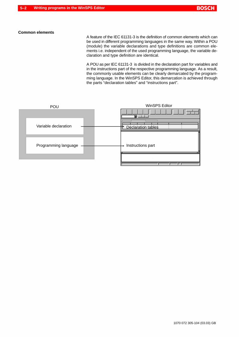
Common elementsA feature of the IEC 61131-3 is the definition of common elements which canbe used in different programming languages in the same way. Within a POU(module) the variable declarations and type definitions are common ele-ments i.e. independent of the used programming language, the variable de-claration and type definition are identical.
A POU as per IEC 61131-3 is divided in the declaration part for variables andin the instructions part of the respective programming language. As a result,the commonly usable elements can be clearly demarcated by the program-ming language. In the WinSPS Editor, this demarcation is achieved throughthe parts “declaration tables” and “instructions part”.
Variable declaration
Programming language
POU
Instructions part
Declaration tables
WinSPS Editor

Writing programs in the WinSPS Editor 5–3
1070 072 305-104 (03.03) GB
5.1 Declaration tables
With the help of the declaration tables, the input of variables and data typesis simplified. All inputs are converted into the syntax of the IEC so that theerrors can be minimised.
The inputs can however also be made without declaration tables in pure textprogramming. The switchover between the declaration tables and text inputtakes place from the button:
The declaration is divided in various input masks (tables) which are repre-sented by three tabs:
D POU type (general data)D Variable declarationD Data type definitions (user-defined, local)
5.1.1 POU type
In the input mask, general data concerning the current module (POU = Pro-gram Organisation Unit) is specified.
Example of a POU of the type PROGRAM with the name SIMPLE
CAUTIONIf you make modifications in an input field, you must confirm the in-put before loading the file in the controller.Changes are accepted only after the confirmation – e.g. using the<Enter> or <Tab> key!
POU nameNormally, the POU name initially corresponds to the current filename *.IL or.*.ST. The name can be changed and may not be identical to the filename.The length of the POU name may not be more than 32 characters. Specifica-tions for the identifiers of the IEC are to be followed, refer to section 7.1.2.

Writing programs in the WinSPS Editor5–4
1070 072 305-104 (03.03) GB
POU typeThe characteristic of the module is determined from the POU type. The threePOU types PROGRAM, FUNCTION_BLOCK and FUNCTION are specifiedusing the selection switch.
FUN ReturnTypeIn case of a POU of the type FUNCTION, the data type of the function valuecan be selected in the field FUN ReturnType.
CommentThe large input field in the lower area allows the entry of any comment text.This text is placed at the top of the file. No comment markings should be ent-ered, these are automatically added by WinSPS.
Further information concerning the POU can be found in section 6.1.
5.1.2 Variable declaration
In this table, the variables of the current POU are edited. Every used variablemust be declared.
Every variable is represented by a row of the table. In order to enter a newvariable, select an empty row. In order to change an existing entry, positionon the row or the column to be changed. In order to delete a variable, afterpositioning, press the button:
CAUTIONIf you make modifications in an input field, you must confirm the in-put before loading the file in the controller.Changes are accepted only after the confirmation – e.g. using the<Enter> or <Tab> key!
Variable typeA selection window opens on clicking a field in the variable type. The selec-tion option changes depending upon the POU type. The following tableshows the possible variable types and the POU types, in which these areavailable:
Writing programs in the WinSPS Editor 5–5
1070 072 305-104 (03.03) GB
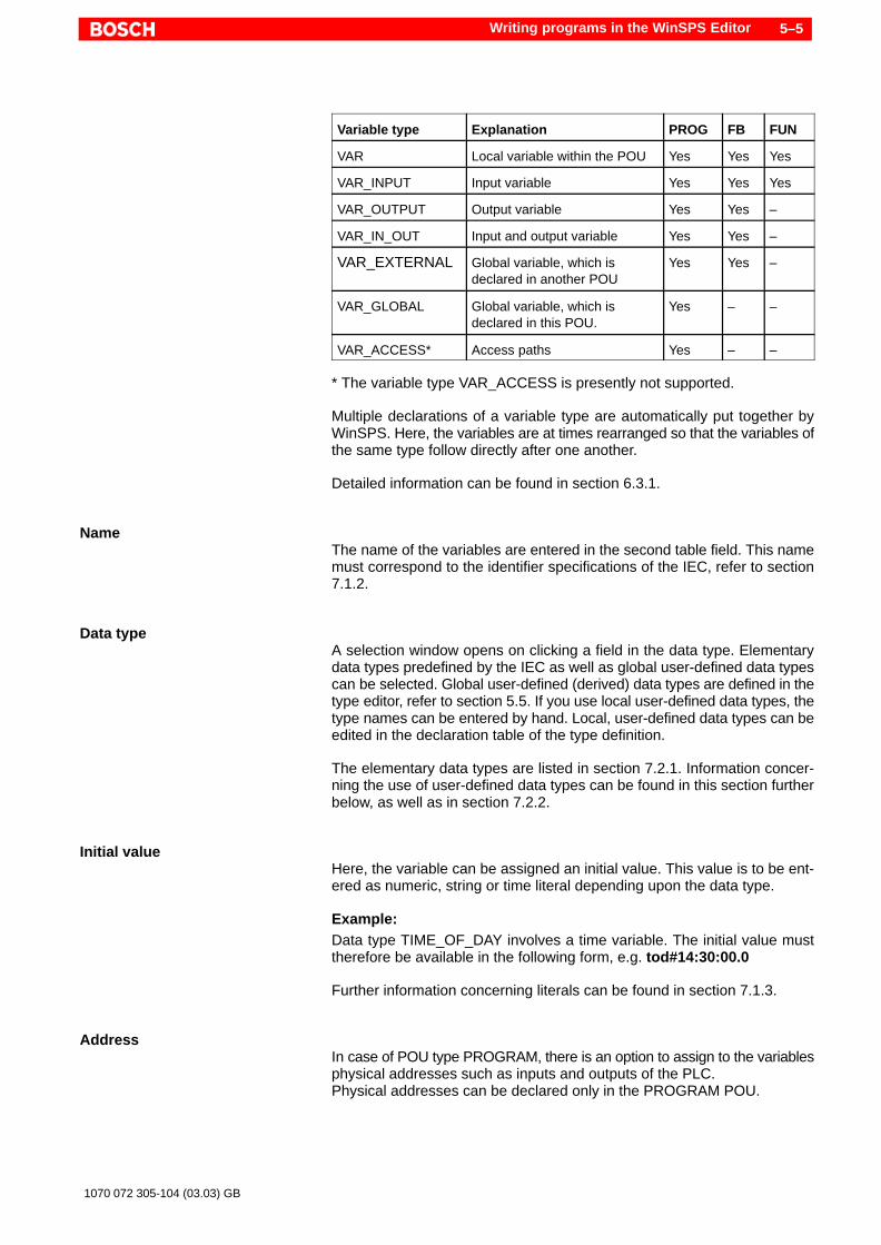
Variable type Explanation PROG FB FUN
VAR Local variable within the POU Yes Yes Yes
VAR_INPUT Input variable Yes Yes Yes
VAR_OUTPUT Output variable Yes Yes –
VAR_IN_OUT Input and output variable Yes Yes –
VAR_EXTERNAL Global variable, which isdeclared in another POU
Yes Yes –
VAR_GLOBAL Global variable, which isdeclared in this POU.
Yes – –
VAR_ACCESS* Access paths Yes – –
* The variable type VAR_ACCESS is presently not supported.
Multiple declarations of a variable type are automatically put together byWinSPS. Here, the variables are at times rearranged so that the variables ofthe same type follow directly after one another.
Detailed information can be found in section 6.3.1.
NameThe name of the variables are entered in the second table field. This namemust correspond to the identifier specifications of the IEC, refer to section7.1.2.
Data typeA selection window opens on clicking a field in the data type. Elementarydata types predefined by the IEC as well as global user-defined data typescan be selected. Global user-defined (derived) data types are defined in thetype editor, refer to section 5.5. If you use local user-defined data types, thetype names can be entered by hand. Local, user-defined data types can beedited in the declaration table of the type definition.
The elementary data types are listed in section 7.2.1. Information concer-ning the use of user-defined data types can be found in this section furtherbelow, as well as in section 7.2.2.
Initial valueHere, the variable can be assigned an initial value. This value is to be ent-ered as numeric, string or time literal depending upon the data type.
Example:Data type TIME_OF_DAY involves a time variable. The initial value musttherefore be available in the following form, e.g. tod#14:30:00.0
Further information concerning literals can be found in section 7.1.3.
AddressIn case of POU type PROGRAM, there is an option to assign to the variablesphysical addresses such as inputs and outputs of the PLC.Physical addresses can be declared only in the PROGRAM POU.

Writing programs in the WinSPS Editor5–6
1070 072 305-104 (03.03) GB
Example:The PLC input 3.0 should be assigned to a variable name: The input field“Address” contains %IX3.0. The data type must be BOOL.
Information concerning format and the use of physical addresses can befound in section 7.3.4.
AttributeThe IEC defines attributes, using which other features can be assigned tothe variables. A selection window opens on clicking an attribute field in thedata type. The following table shows all attributes and their meaning:
Attribute Explanation
RETAIN Battery backed-up, remanent
CONSTANT Constant
R_EDGE Rising edge
F_EDGE Falling edge
READ_ONLY Wite-protected
READ_WRITE Reading and writing access
* The attributes related to the edge control are presently not supported. Edgecontrol can be realised using the standard function blocks R_TRIG andF_TRIG, refer to section.
. All variables are basically handled as with RETAIN attribute. Excep-tions are the standard FBs. These are basically not remanent i.e. theyare re-initialized after every STOP/RUN switchover.The remnance characteristic can moreover be configured in the orga-nisation module OM2. Follow the instructions in the software manual“PCL and CL550 (order no. 1070 072 189) or in “iPC” (order no. 1070 073875.
Allowed attributes of the individual variable types are listed in the followingtable:
Variable type RETAIN CONSTANT R_EDGEF_EDGE
READ_ONLYREAD_WRITE
VAR Yes Yes – –
VAR_INPUT – – Yes –
VAR_OUTPUT Yes – – –
VAR_IN_OUT – – – –
VAR_EXTER-NAL
– – – –
VAR_GLOBAL Yes Yes – –
VAR_ACCESS* – – – Yes
* The variable type VAR_ACCESS is presently not supported.
Further information concerning attributes are listed in section 7.3.8.

Writing programs in the WinSPS Editor 5–7
1070 072 305-104 (03.03) GB
Monitor dataIn this column, the current process data of the variables is shown in the moni-tor of the WinSPS. This column cannot be edited.
CommentHere, entry of any comment is possible. The comment is given at the end ofthe line of the variable declaration. No comment markings should be ent-ered, these are automatically added by WinSPS.
ExampleThe following example shows multiple variable declarations. Subsequently,the conversion of the example into the textual presentation shows:
Example of different variable declarations (illustrative)
VAR Local AT %Q1.0 : BOOL; (* any comment *)END_VAR
VAR_INPUT InOut : LREALEND_VAR
VAR_INPUT In1 : INT := 15; In2 : DATE;END_VAR
VAR_OUTPUT RETAIN Out : WORDEND_VAR
VAR_GLOBAL Global : WORDEND_VAR
VAR_EXTERNAL Global : WORDEND_VAR
Textual presentation of the above-mentioned example (illustrative)

Writing programs in the WinSPS Editor5–8
1070 072 305-104 (03.03) GB
5.1.3 Type definition
In this part, derived data types of the current POU can be defined. Deriveddata types – also called type definition – are user defined data types whichare based on the “elementary data types”. With type definitions, new datatypes with extended or altered attributes can be generated. In addition tothis, very complex data models can be realised.
The following can be defined:
D User-defined data typesD Data structuresD Enumerations
The type definitions are valid only for the current module (POU). Here, it alsoinvolves local type definitions. Global type definitions are made in the symboleditor with the help of the editor for global data types, refer to section 5.5.
CAUTIONIf you make modifications in an input field, you must confirm the in-put before loading the file in the controller.Changes are accepted only after the confirmation – e.g. using the<Enter> or <Tab> key!
Type nameThe input field for the type names is used in three different ways. Detailedexamples are to be found in later part of this section.
4. Keyword TYPE (standard):The keyword TYPE stands for the complete type definition of the currentPOU and is as a result, at a level higher than all other definitions such asdata structures and enumerations. All table entries under this keywordare accepted in the POU as user-defined type definitions .In the pure textual presentation, these type definitions are placed bet-ween the keywords TYPE and END_TYPE.
5. Enumeration, ENUM:Enumerations are specified using the type names. Enter the name of theenumeration in the edit field “Type name” . Delimited by comma, the enu-meration elements are entered in the table in the field “Data type” bet-weeen two brackets ( ) . The table field “Name” must be empty.In the pure textual presentation, these enumerations are placed betweenthe keywords TYPE and END_TYPE. Enumerations are a part of thecomplete local type definition.
6. Data structures, (STRUCT):Complex data structures are not created through the standard typeTYPE. Instead, any name, to be precise the structure name, is entered inthe edit field. In the table , the type definitions of all the sub-elements aresubsequently assigned to this structure . In the pure textual presentation, these type definitions are placed bet-ween the keywords TYPE and END_TYPE. The structure name is speci-fied right before this structure block. The structure itself is found betweenTYPE and END_TYPE. Structures are a part of the complete local typedefinition.
Writing programs in the WinSPS Editor 5–9
1070 072 305-104 (03.03) GB
If within a local type definition, various types are to be put together, e.g. datastructures and enumerations, these must be entered one after the otherusing the field “Type name”. A detailed example for this can be found at theend of the type definition description.
In order to enter a new type definition, select an empty row in the table. Inorder to change an existing entry, position the write cursor on the row or thecolumn to be changed. In order to delete a type definition, after positioning,press the button:
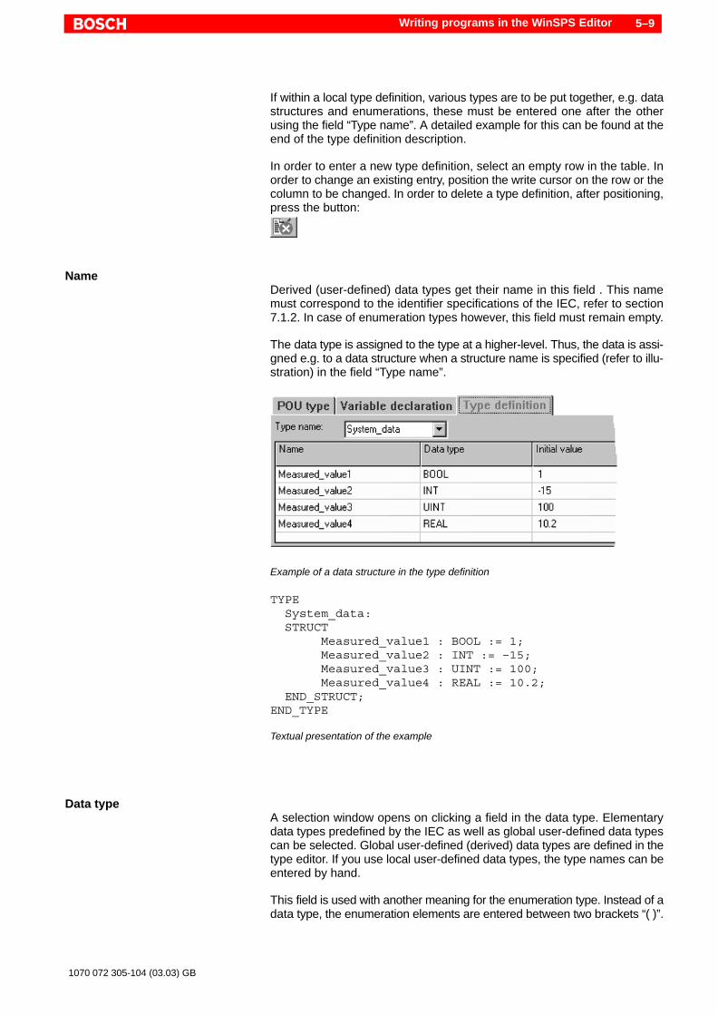
NameDerived (user-defined) data types get their name in this field . This namemust correspond to the identifier specifications of the IEC, refer to section7.1.2. In case of enumeration types however, this field must remain empty.
The data type is assigned to the type at a higher-level. Thus, the data is assi-gned e.g. to a data structure when a structure name is specified (refer to illu-stration) in the field “Type name”.
Example of a data structure in the type definition
TYPE System_data: STRUCT Measured_value1 : BOOL := 1; Measured_value2 : INT := –15; Measured_value3 : UINT := 100; Measured_value4 : REAL := 10.2; END_STRUCT;END_TYPE
Textual presentation of the example
Data typeA selection window opens on clicking a field in the data type. Elementarydata types predefined by the IEC as well as global user-defined data typescan be selected. Global user-defined (derived) data types are defined in thetype editor. If you use local user-defined data types, the type names can beentered by hand.
This field is used with another meaning for the enumeration type. Instead of adata type, the enumeration elements are entered between two brackets “( )”.

Writing programs in the WinSPS Editor5–10
1070 072 305-104 (03.03) GB
The elementary data types are listed in section 7.2.1. Information concer-ning the use of global user-defined data types can be found in section 5.5.
Initial valueHere, an initial value can be assigned. This value is to be entered as nume-ric, string or time literal depending upon the data type. Information concer-ning literals can be found in section 7.1.3.
CommentHere, entry of any comment is possible. The comment is given at the end ofthe line. No comment markings should be entered, these are automaticallyadded by WinSPS.
Example:
The following example shows the approach in case of complex type defini-tions which put together various types within a local type definition. The il-lustrations show working steps to be performed one after the other.Afterwards, the result is indicated with the help of the textual presentation:
1. Step: User–defined data types
2. Step: Definition of an enumeration
Writing programs in the WinSPS Editor 5–11
1070 072 305-104 (03.03) GB
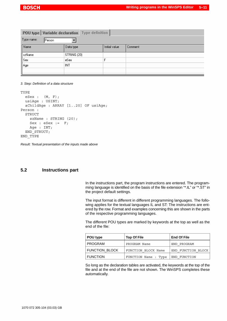
3. Step: Definition of a data structure
TYPE eSex : (M, F); usiAge : USINT; aChildAge : ARRAY [1..20] OF usiAge; Person : STRUCT szName : STRING (20); Sex : eSex := F; Age : INT; END_STRUCT;END_TYPE
Result: Textual presentation of the inputs made above
5.2 Instructions part
In the instructions part, the program instructions are entered. The program-ming language is identified on the basis of the file extension “*.IL” or “*.ST” inthe project default settings.
The input format is different in different programming languages. The follo-wing applies for the textual languages IL and ST: The instructions are ent-ered by the row. Format and examples concerning this are shown in the partsof the respective programming languages.
The different POU types are marked by keywords at the top as well as theend of the file:
POU type Top Of File End Of File
PROGRAM PROGRAM Name END_PROGRAM
FUNCTION_BLOCK FUNCTION_BLOCK Name END_FUNCTION_BLOCK
FUNCTION FUNCTION Name : Type END_FUNCTION
So long as the declaration tables are activated, the keywords at the top of thefile and at the end of the file are not shown. The WinSPS completes theseautomatically.

Writing programs in the WinSPS Editor5–12
1070 072 305-104 (03.03) GB
If these declaration tables are deactivated, e.g. using the button:
the instructions part then corresponds to the area between the last variabledeclaration – ending with the keyword END_VAR – and the POU end – be-fore the keyword END_x (where x corresponds to the POU type, refer to thetable above). All program instructions must be entered within this part.
5.3 Error messages
In the IEC editor, the lower window area is used for displaying errors afterchecking. The checking is activated from the menu functions File " Createnew project and File " Compile module – even using the button:
and also during the program loading, refer to section 10.
In this case, the error message display is erased. On completion of the chek-king, the error-free run or all errors are indicated. Unless specified other-wise, the display is based on the current file.
Example of an error-free checking
Checking/compilingThe following text appears in case of error-free checking:
POU name – 0 error(s), 0 warning(s)
Error messages of the compiler (refer to section 10.1) have the followingstructure:
(R,C) Error in the ...part : Error (ID)
R indicates the row number – C the column number, in which the error hasoccurred. Subsequently follows the instruction whether the error lies in thevariable part(declaration part) or in the program part (instructions part). Afterthe colon, a description of the error or the warning is displayed in the plaintext. At the end of the row, an internal identification number ID is outputted inbrackets. In this case, differentiation is made between warnings with theidentification W and errors with the identification F.

Writing programs in the WinSPS Editor 5–13
1070 072 305-104 (03.03) GB
Example:
(5,3) Error in the variable part : Syntax error!(E4006)
The first bracket shows that the error lies in row 3 and column 5 of the currentmodule. The error was made in the declaration part of the module. It involvesa syntax error, which means that the program text does not comply with theformation rules of the programming language. In the bracket at the end, theinternal error identification for syntax error 4006 is indicated.
With a double-click on the error message, the write cursor is set in the rowcontaining the error. Thus, errors can be processed directly.
Kindly keep in mind that errors could give rise to consequent errors. So un-der certain circumstances, the test result shows multiple errors in a programrow although there may be only one error. This is a typical characteristic ofcompilers.
Linker – Create new projectEven the linker (refer to section 10.2) uses the window for the error output.With the linker however, no clear error localization within a module can becarried out and indicated. However, the filename of the POU , in which theerror is assumed, is indicated.
The example in the illustration shows a linker error due to an incompatibledata type in the module “HANS”.
Error message of the linker (Create new project)
5.4 Global variable declaration – variable editor
Under preparation.

Writing programs in the WinSPS Editor5–14
1070 072 305-104 (03.03) GB
5.5 Global type definition – type editor
In the editor for global type definition, derived data types can be defined glo-bally. Derived data types – also called type definition – are user defined datatypes which are based on the “elementary data types”. With type definitions,new data types with extended or altered attributes can be generated. In addi-tion to this, very complex data models can be realised. Global means that thedata types can be used in every POU.
. All global type definitions are written and in the internal file“Bosch.Typ” and are managed there by WinSPS. If already generatedglobal type definitions can be drawn for other PLC projects, this filecan be copied to the corresponding project folder.
The type editor can be called up within the symbol editor using the followingbutton:
The following can be defined:
D User-defined data typesD Data structuresD Enumerations
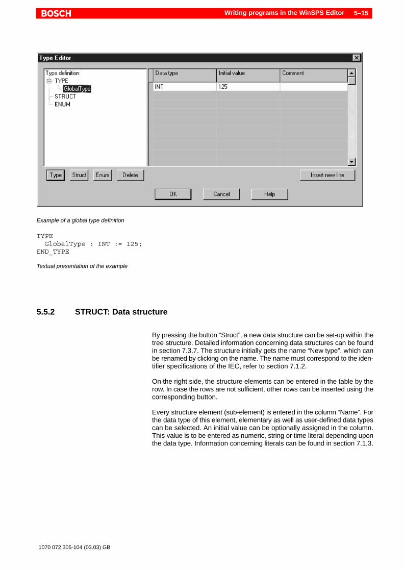
5.5.1 TYPE: Data Type
Here, a user-defined (derived) data type can be defined. Detailed informa-tion concerning these data types can be found in section 7.2.2. By pressingthe button “Type”, a new data type can be set-up within the tree structure.The new data type initially gets the type name “New type”, which can be re-named by clicking on the name. The name must correspond to the identifierspecifications of the IEC, refer to section 7.1.2.
On the right side, a row is available for inputting the data type, an initial valueand comments.
Elementary as well as user-defined data types can be selected. An initialvalue can be optionally assigned in the column. This value is to be entered asnumeric, string or time literal depending upon the data type. Information con-cerning literals can be found in section 7.1.3.
Writing programs in the WinSPS Editor 5–15
1070 072 305-104 (03.03) GB
Example of a global type definition
TYPE GlobalType : INT := 125;END_TYPE
Textual presentation of the example
5.5.2 STRUCT: Data structure
By pressing the button “Struct”, a new data structure can be set-up within thetree structure. Detailed information concerning data structures can be foundin section 7.3.7. The structure initially gets the name “New type”, which canbe renamed by clicking on the name. The name must correspond to the iden-tifier specifications of the IEC, refer to section 7.1.2.
On the right side, the structure elements can be entered in the table by therow. In case the rows are not sufficient, other rows can be inserted using thecorresponding button.
Every structure element (sub-element) is entered in the column “Name”. Forthe data type of this element, elementary as well as user-defined data typescan be selected. An initial value can be optionally assigned in the column.This value is to be entered as numeric, string or time literal depending uponthe data type. Information concerning literals can be found in section 7.1.3.
Writing programs in the WinSPS Editor5–16
1070 072 305-104 (03.03) GB
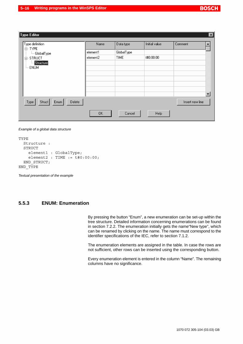
Example of a global data structure
TYPE Structure : STRUCT element1 : GlobalType; element2 : TIME := t#0:00:00; END_STRUCT;END_TYPE
Textual presentation of the example
5.5.3 ENUM: Enumeration
By pressing the button “Enum”, a new enumeration can be set-up within thetree structure. Detailed information concerning enumerations can be foundin section 7.2.2. The enumeration initially gets the name“New type”, whichcan be renamed by clicking on the name. The name must correspond to theidentifier specifications of the IEC, refer to section 7.1.2.
The enumeration elements are assigned in the table. In case the rows arenot sufficient, other rows can be inserted using the corresponding button.
Every enumeration element is entered in the column “Name”. The remainingcolumns have no significance.

Writing programs in the WinSPS Editor 5–17
1070 072 305-104 (03.03) GB
Example of a global enumeration
TYPE Enumerate: (red, blue, pink);END_TYPE
Textual presentation of the example
TYPE GlobalType : INT := 125; Enumerate: (red, blue, pink); Structure : STRUCT element1 : GlobalType; element2 : TIME := t#0:00:00; END_STRUCT;END_TYPE
Summary of all the examples shown in this section

Writing programs in the WinSPS Editor5–18
1070 072 305-104 (03.03) GB
5.6 Constant definition – DEFINE Editor
Constants can be generated locally and globally with the help of the variableattribute “CONST”, also refer to section 7.3.8. In addition to this, global con-stants can be set-up with the “DEFINE editor”. This is called up within thesymbol editor by pressing the button:
Every row in the define editor corresponds to a constant. The name mustcorrespond to the identifier specifications of the IEC, refer to section 7.1.2.The value of the constant is assigned in the column initial value. Numeric ortime literals can be entered. Information concerning literals can be found insection 7.1.3. The information concerning a data type is not required.
. During the subsequent use of the constants in the program, attentionmust be paid to the data type compatibility.
Model entries for constants in the define editor

Program Structure 6–1
1070 072 305-104 (03.03) GB
6 Program Structure
A great advantage of the IEC 61131-3 is the specification of common ele-ments, which can be used globally for all the programming languages. Theprogram structure , which is standardized with the design, contents and in-terfaces of various module types. The IEC terms the modules “Program Or-ganization Units”, in short: POU.
6.1 Program Organization Units– modules of the IEC
In the IEC 61131-3, modules are termed as Program Organization Units(POU) . It involves closed program units, which receive values from outside,process these values in the instructions part and supply results outwards.
A POU is divided in the declaration part for variables and in the instructionspart of the respective programming language. In the editor of the WinSPS,this corresponds to the input areas “Declaration tables” and “Instructionspart”, refer to the illustration. Further information concerning the use of aPOU in the WinSPS Editor can be found in section 5.
Variable declaration
Programming language
POU
Instructions part
Declaration tables
WinSPS Editor
In the pure textual illustration without declaration tables, all elements of aPOU are visible. The following elements form the structure of a POU:
D Data concerning the POU type and the POU name (in case of functions,additionally the data type of the function value)
D Declaration partD Instructions partD POU end

Program Structure6–2
1070 072 305-104 (03.03) GB
ExampleThe following example shows the structure of a POU. The programming lan-guage is basically not relevant for the structure of the POU, however, it is re-levant for the input form of the program statements. In this example, theprogramming language ST was used:
PROGRAM SIMPLE
VAR OUTPUT AT %Q8.7 : BOOL; INPUT AT %I8.3 : BOOL;END_VAR
OUTPUT := NOT INPUT;
END_PROGRAM
Type and name of the POU
Declaration part
Instructions part
POU end
Structure of a POU
The declaration part begins after the specification of POU type and POUname and ends with the last declaration block.
The instructions part begins after the last declaration block – ending withthe keyword END_VAR. The instructions part ends before the keywordEND_x, where x corresponds to the POU type.

Program Structure 6–3
1070 072 305-104 (03.03) GB
6.2 POU types
For the structuring of a PLC program, three POU types (module types) areavailable:
PROGRAM
FUNCTION_BLOCK
FUNCTION
Main program
Function block
Function
Program structuringThe structuring of the application program is achieved by dividing the task tobe processed into sub-tasks. Each of these sub-tasks is placed in a POU.The POUs can be called from each other so that the calling POU is interrup-ted and the program processing continues in the called POU. After proces-sing this POU, the program control returns to the calling POU and theprocessing is continued. Further information in this regard can be found insection 6.5.
Identification of a POUThe different POU types are marked by keywords at the beginning and endof the file. At the top of the file, the name of the POU is specified after thekeyword. In case of a function, the data type of the function value is specifiedadditionally:
POU type Top Of File End Of File
PROGRAM PROGRAM Name END_PROGRAM
FUNCTION_BLOCK FUNCTION_BLOCK Name END_FUNCTION_BLOCK
FUNCTION FUNCTION Name : Type END_FUNCTION
In the WinSPS Editor, these keywords are not visible so long as the “declara-tion tables” are activated, refer to section 5.1.
. The short names PROG, FB and FUN mentioned below were selectedonly for this document and may not be used in place of the keywordswhile programming.

Program Structure6–4
1070 072 305-104 (03.03) GB
6.2.1 Main program – PROGRAM
Key word: PROGRAM, short name: PROG
This module has exactly one occurrence for each central processing unit.Exception: Multitasking (not currently supported by Bosch). The main pro-gram runs through the cyclic processing in the PLC.
PLC peripherals and communication
In the main program, the assignment of the PLC peripherals is made. Globalvariables and access paths can be declared here. In the other POU types,the same is not possible.
The use of the variable type VAR_ACCESS for the global PLC communica-tion is presently not possible.
InterfaceThe program may call up function blocks and functions.
Mixed programmingIn case of mixed programming with classical programming languages, theremay not be any PROGRAM POU. The main program is instead realized withthe help of the organization module OM1, refer to section 11.2.
Entry in the symbol fileThe symbol file is automatically managed by WinSPS during the generationof IEC programs. In case of mixed programming mentioned above, a few en-tries must however be made in the symbol file by hand, refer to section 11.4.
Example of a PROGRAM POU (programming language ST):PROGRAM CTU_PROG (* POU type and name *)
VAR (* Declaration part *) Counter : CTU_FB; AT %Q4.0 : BOOL; AT %Q4.1 : BOOL; Set1 AT %I4.0 : BOOL; Set2 AT %I4.1 : BOOL; Res AT %I4.2 : BOOL;END_VAR (* Instructions part *)
Counter (Set_1:=Set1, Set_2:=Set2, Res:=Res); %Q4.0 := Counter.C1_Max; %Q4.1 := NOT Counter.C1_Max;
END_PROGRAM (* POU end *)

Program Structure 6–5
1070 072 305-104 (03.03) GB
Declaration and instructions of a PROGRAM POU in the WinSPS Editor, also refer to section 5.1.
6.2.2 Function block – FUNCTION_BLOCK
Key word: FUNCTION_BLOCK, short name: FB
Function blocks form an important structuring element for PLC programsdue to numerous useful characteristics.
InterfaceA function block may call up other function blocks and functions. Recursivecalls are not allowed, refer to section 6.5.2.
A function block may not have any input parameter, or it may have one ormore input parameters. Likewise, a function block may not have any outputparameter, or it may have one or more output parameters. The access to thisdata is discussed in section 6.5.3.
While calling up a function block, not all input parameters need to be speci-fied. The missing input parameters retain their values from the previous callor are initialized with initial values. The initial values are specified in the de-claration part of the FB. If this data is missing, the standard values of the datatype are used, refer to section 7.2.1.
ValidityFunction blocks are locally valid. They must be declared in the calling POU.The declaration of FBs is also termed as instance building or instancing.
Instance buildingFrom the function block, multiple instances can be built; these occupy inde-pendent memory locations for inputs, output and intermediate results. Thefunction block itself is not called up, instead, always an instance of the func-tion block is called up. The principle of the instance building is illustrated indetail in section 6.6.

Program Structure6–6
1070 072 305-104 (03.03) GB
Module with memoryFunction blocks have a “memory”, i.e. the local variables of the module retaintheir (instance specific) value across various calls . This is an independentcharacteristic when for example, counter functionalities are to be built. Thus,through this instance building, multiple counters of the same type can bebuilt. Every counter has its own memory. They do not influence each other.
Standard function blocksIn addition to the syntax of the programming languages, the IEC 61131-3also standardizes important PLC functionalities. These are predefined in thenorm as “Standard functions” or “Standard function blocks”. All manufactu-rers of programming systems or module libraries must follow these direc-tions at the time of implementation.
The standard function blocks are listed in section 12.2.
In addition to this, manufacturers can offer other function blocks. Even theuser can plan his own FBs, which can be used globally across the project(FB library).
Example of a function block (programming language ST):FUNCTION_BLOCK CTU_FB (* POU type and name *)
VAR_INPUT (* Declaration part *) Set_1 : BOOL; Set_2 : BOOL; Res : BOOL;END_VAR
VAR_OUTPUT C1_Max : BOOL;END_VAR
VAR Counter_1 : CTU; Counter_2 : CTU; CV1 : INT;END_VAR (* Instructions part *)
Counter_1 (CU:=Set_1, RESET:=Res, PV:=20); Counter_1 (CU:=Set_1, RESET:=Res, PV:=20); C1_Max := CTU_FUN (Counter_1.CV, Counter_2.CV); CV1 := Counter_1.CV;
END_FUNCTION_BLOCK (* POU end *)

Program Structure 6–7
1070 072 305-104 (03.03) GB
Declaration and instructions of a FB POU in the WinSPS Editor, also refer to section 5.1.
6.2.3 Function – FUNCTION
Keyword: FUNCTION, short name: FUN
Functions are used to deliver an unambiguous result through by processingthe input parameters. As a result, functions are used for recurring tasks suchas mathematical functions.
InterfaceA function may call up other functions. Recursive calls are not allowed, referto section 6.5.2.
Functions may not have any input parameter, or they may have one or moreinput parameters and may return exactly one function value. The access tothis data is discussed in section 6.5.3.
With every call to the function, all input parameters are to be specified.
ValidityFunctions are globally valid. They are as a result, available for all POUs andtherefore, they must not be declared in the calling POU.
Module without memoryA function may use local variables for intermediate results, they however donot retain their value across various calls. A function therefore has no ’me-mory’, i.e. for the same inputs, it always supplies the same result.
Standard functionsIn addition to the syntax of the programming languages, the IEC 61131-3also standardizes important PLC functionalities. These are predefined in thenorm as “Standard functions” or “Standard function blocks”. All manufactu-rers of programming systems or module libraries must follow these direc-tions at the time of implementation.

Program Structure6–8
1070 072 305-104 (03.03) GB
The standard functions are listed in section 12.1 . In this regard, also pay at-tention to the characteristics of “common data types” in section 7.2.3.
In addition to this, manufacturers can offer other functions. Users can plantheir own functions, which can be used globally across the project (Functionslibrary).
Example of a function (programming language ST):FUNCTION CTU_FUN : BOOL (* POU type, name and function value *)
VAR_INPUT (* Declaration part *) CV_1 : INT := 0; CV_2 : INT := 0;END_VAR (* Instructions part *)
CTU_FUN := CV_1 > CV_2;
END_FUNCTION (* POU end *)
Declaration of a function POU in the WinSPS Editor, also refer to section 5.1.
6.3 Declaration part
In the declaration part of a POU, variables are assigned to a specific datatype (declared). Here, assignments related to physical addresses can bemade and other characteristics can be fixed, also refer to section 5.1.
Moreover, in the declaration part of a POU, local, user-defined data types arefixed, refer to section 7.2.2.
The declaration part is located at the beginning of the POU. It is independentof the programming language used.

Program Structure 6–9
1070 072 305-104 (03.03) GB
6.3.1 Variable types
Different types of variables characterize different application purposes of thevariables. A differentiation is made between local variables and variableswhich are visible from outside (call interfaces, also refer to section 6.5.3).
Depending upon the variable type, variables are integrated into a block.Block beginning is formed by the keyword “VAR...”. Every block ends with“END_VAR”. The frequency of same variable types and their sequence canbe anything. The WinSPS integrates scattered variables of the same varia-ble type automatically into one block during inputs into the “declaration ta-bles”. The formation rules and names for variables can be found in section7.3.
With the help of a few examples, the following list shows all possible types ofvariables:
Local variableThe local variable is valid only inside the POU in which it was declared. In thisexample, a physical address is assigned.
VAR Local AT %Q1.0 : BOOL;END_VAR
Input variableAn input variable is declared when the variable is only to be read within aPOU or when it is to be used for the parameter transfer to a function or a func-tion block . As a result, the variable may not be changed in this POU. In thecalling POU, the variable name is used as “formal parameter” , refer to sec-tion 6.5.3.
In the example, there are two input variables. The formal parameters are“In1” and “In2”. The variable “In1” moreover was assigned the “Initial value”15, refer to section 6.5.3.Also pay attention to the remark “Use of input and output parameters” in sec-tion 6.5.3.
VAR_INPUT In1 : INT := 15; In2 : DATE;END_VAR
Output variableIn contrast to the input variables, the output variables for a function blockmay be changed in the POU. In the calling POU, it may only be read.
The example moreover shows the use of the variable attribute “RETAIN”,refer to section 7.3.8.Also pay attention to the remark “Use of input and output parameters” in sec-tion 6.5.3.
VAR_OUTPUT RETAIN Out : WORDEND_VAR

Program Structure6–10
1070 072 305-104 (03.03) GB
Input and output variableAn IN_OUT variable is read by the FB, processed and outputted under thesame name. With it, the characteristics of the VAR_INPUT and theVAR_OUTPUT variables can be combined.Also pay attention to the remark “Use of input and output parameters” in sec-tion 6.5.3.
VAR_IN_OUT InOut : LREALEND_VAR
DANGERVAR_IN_OUT cannot be assigned an initial value. The initializationcan take place with the specification of the corresponding formal pa-rameters instead of in the FB calls.In case initial values are specified within VAR_IN_OUT, WinSPS doesnot generate any error message during compilation or linking. Theinitial values are however not set in the controller!
Global variableA variable is declared as ”global variable” if it is valid for a program and in allfunction blocks which are called up from this program. A global variable de-clared in the program is known inside the program as well as inside the FBs,which can be called up from this program. In all the called up FBs, in whichthis global variable is to be used, it must be declared as VAR_EXTERNALwith the same identifier (name).
VAR_GLOBAL Global : WORDEND_VAR
External variableIf a global variable is to be used inside a function block, it must be declared as”VAR_EXTERNAL” with the same identifier (name) and data type as underVAR_GLOBAL.In functions, global variables cannot be used.
VAR_EXTERNAL Global : WORDEND_VAR
Access pathsAccess paths across the project.
. The variable type VAR_ACCESS is presently not supported by Boschcontroller!
VAR_ACCESS Path : CPU_1.Simple.Param_1 : WORDEND_VAR

Program Structure 6–11
1070 072 305-104 (03.03) GB
All above-mentioned examples are summarized in the declaration tables of the WinSPS Editor (illustrative), also refer to section 5.1.
6.3.2 Applicability and access options of the variable types
Depending upon the POU type, different types of variables are allowed:
Variable type Explanation PROG FB FUN
VAR Local variable within the POU Yes Yes Yes
VAR_INPUT Input variable Yes Yes Yes
VAR_OUTPUT Output variable Yes Yes –
VAR_IN_OUT Input and output variable Yes Yes –
VAR_EXTERNAL Global variable, which isdeclared in another POU
Yes Yes –
VAR_GLOBAL Global variable, which isdeclared in this POU.
Yes – –
VAR_ACCESS* Access paths Yes – –
* The variable type VAR_ACCESS is presently not supported
The following examples should illustrate the access options of variables. Anexternal access implies processing inside the calling POU. The internal ac-cess characterizes the behavior inside the POU, in which the variable wasdeclared.
Variable type External access Internal access
VAR – writing / reading
VAR_INPUT writing reading
VAR_OUTPUT reading writing / reading
VAR_IN_OUT writing / reading writing / reading
VAR_EXTERNAL writing / reading writing / reading
VAR_GLOBAL writing / reading writing / reading
VAR_ACCESS* writing / reading writing / reading
Program Structure6–12
1070 072 305-104 (03.03) GB
* The variable type VAR_ACCESS is presently not supported!
It is evident from the table that only the variable type VAR does not offer anyoption for the external access. All other types of variables are suitable for thedata exchange between POUs.
The variable types VAR_INPUT and VAR_OUTPUT provide a mechanismthat prevents undesired manipulation.
. While using input and output parameters, pay attention to the instruc-tions under section 6.5.3.
6.4 Instructions part
The declaration part is followed by the instructions part (body) of a POU. Inthe instructions part, the PLC instructions to be executed are entered in therespective programming language.
The description of the programming in the instructions part follows in thechapters on the programming languages:
D Instruction list (IL), chapter 8D Structured Text (ST), chapter 9
6.5 Calls between POUs
An application program can be structured using the call option of POUs. Thesyntax of the calls is different among the programming languages. Detailedinformation in this regard can be obtained in the related sections of the re-spective programming language.
6.5.1 Call hierarchy
The following rules apply for the mutual calls to the program organizationunits (POU), also refer to the illustration below:
D PROGRAM may call up FUNCTION_BLOCK and FUNCTION.D FUNCTION_BLOCK may call up FUNCTION or FUNCTION_BLOCK.D FUNCTION may call up only FUNCTION.

Program Structure 6–13
1070 072 305-104 (03.03) GB
PROGRAM FUNCTION_BLOCK
FUNCTION FUNCTION
FUNCTION
FUNCTION_BLOCK
Calling up options of the individual POU types
6.5.2 Recursive calls
DANGERRecursive calls (calling up self) are not allowed. Even indirect recur-sive calls are not allowed! Recursive calls can be detected throughthe checking by WinSPS only in a limited way.Through recursive calls, the maximum PLC cycle time is exceededand the controller are stopped!
Example of a recursive call (ST):FUNCTION recursive : INT
VAR_INPUT Par01, Par02 : INT;END_VAR
Recursive := Par01 + Recursive (Par01, Par02);
END_FUNCTION
The example shows the function “Recursive”. Inside this function, the samefunction is again called up. This leads to an endless loop of function calls.The program does not respond any more and cannot be interrupted. It leadsto controller stoppage since the program cycle time is exceeded.

Program Structure6–14
1070 072 305-104 (03.03) GB
Example of an indirect recursive call (ST):FUNCTION Fun_1 : INT
VAR_INPUT Par01, Par02 : INT;END_VAR
Fun_1 := Par01 + Fun_2 (Par01, Par02);
END_FUNCTION
FUNCTION Fun_2 : INT
VAR_INPUT Par01, Par02 : INT;END_VAR
Fun_2 := Par01 + Fun_1 (Par01, Par02);
END_FUNCTION
The example shows two functions, which when considered individually – donot contain any recursion. The functions however call each other. “Fun_1”calls up “Fun_2” , “Fun_2” again calls up “Fun_1”. This results in a recursivechain of calls – an indirect recursion.
6.5.3 Call interface – parameters during the call
Input parameterParameters can be transferred to functions and function blocks at the time ofcalling up. These parameters can be used for internal processing inside thecalling function or the function block. There, they are termed as input varia-bles . In the calling POU, they are termed as input parameters or actual para-meters.
Output parameterIn case of function blocks, there is an option of transferring the return valuesto the calling POU through output parameters. It is fixed in the declarationpart of the FB, which input and output variables should the function blockhave.
In case of functions, only input variables can be declared. Functions supplyonly one output parameter, the so-called function value or return value.
Formal parameterAt the time of calling up a function or a function block, the variable names ofthe respective input parameter may/must be specified. This name is also re-ferred to as formal parameter. Rules for the use of formal parameters arediscussed in section 6.5.4 and 6.5.5.

Program Structure 6–15
1070 072 305-104 (03.03) GB
Initial valuesInitial values can be specified in the declaration part of the POU to be calledup. If this data is missing, the standard values of the data type are used, referto section 7.2.1. Further information concerning the initialisation can befound in sections 6.5.4 and 6.5.5.
Variable types of the parametersThe following table shows, for which purpose can various variable types beused. A detailed enumeration of all variable types can be found in section6.3.1.
Variable type Comment
Call interface VAR_INPUTVAR_IN_OUT
Input parameter
Return values VAR_OUTPUTVAR_IN_OUTFunction value in caseof FUNCTION
Output parameter
Global interface VAR_GLOBALVAR_EXTERNAL VAR_ACCESS
Global dataand access paths
Local data VAR Only internal POU:no interchange possible
Use of input andoutput parameters:
For the variable types of the call interface and the return values, there aredifferent access methods. Pay attention to the following characteristics:
VAR_INPUTTransfer of not the input variable itself, instead, transfer of a copy (memory)to the POU. This principle is termed as “call by value”. This results in the pro-tection from undesired manipulation within the called POU.
VAR_OUTPUTIn the calling POU, the data can only be read as the output parameters aregenerated only in the called POU (return by value). Output parameters areprotected from being changed in the calling POU.
VAR_IN_OUTIn case of this variable type, there is no access protection, as here only onepointer is transferred to a memory location (call by reference).This principle certainly does not provide any protection, but it can be ideallyused during the transfer of complex data structures. The program proces-sing is very efficient as the variables do not have to be copied during runtime.
DANGERVAR_IN_OUT can not be preset to an initial value. The initializationcan instead take place in the FB call with specification of the corres-ponding formal parameter.In case initial values are specified within the declaration ofVAR_IN_OUT, WinSPS does not generate any error message duringcompilation or linking. The initial values are however not set in thecontroller!

Program Structure6–16
1070 072 305-104 (03.03) GB
ExampleThe following example shows a function block and subsequently a call op-tion in the programming language ST:
FUNCTION_BLOCK FB1VAR_IN Par_1 : BOOL; Par_2 : BOOL;END_VAR
VAR_OUT Out : INT := 0;END_VAR
IF Par_1 = Par_2 THEN Out := Out + 1; END_IF;
END_FUNCTION_BLOCK
The function block “FB1” has two input parameters with the names “Par_1”and “Par_2” of the data type “BOOL”, and the output parameter “Out” ofdata type “INT”.
PROGRAM ABCVAR AT %Q2.0 : BOOL; X1 AT %I2.0 : BOOL; Counter : INT := 0; FB1_Inst : FB1;END_VAR
FB1_Inst (Par_1:=%Q2.0, Par_2:=X1 | Counter := Out);
END_PROGRAM
The program “ABC” shows a call option of the function block “FB1”. The localvariables “%Q2.0” und “X1” are used as input parameters, the output para-meter is assigned to the variable “Counter”.The assignment takes place in the instance call with the specification of theformal parameters “Par_1”, “Par_2” and “Out”.The data types of the local variables and the FB internal variables mustmatch at the transfer interface.

Program Structure 6–17
1070 072 305-104 (03.03) GB
6.5.4 Calling up the function blocks
CallThe call to a function block takes place not through the FB name itself, in-stead through the instance name. This is determined by the “Instance buil-ding”, refer to section 6.6.
Parameter transferThe transfer of input data and the evaluation of output data differ dependingupon the programming language. In the programming language IL and ST,input data is “given” with the call, in brackets and delimited by commas. Theactual parameters are assigned to the formal parameters using “:=”. Out-put parameters can similarly be assigned to the formal parameters in thecall. Input and output parameters are then separated from each other withthe character ”|”, refer to the example below.
The second method for the parameter transfer is the initialization before thecall. In IL, the parameters are initialized through a combination of loading(LD) and assignment operators (ST). In ST, the assignment operator is used,refer to the examples below.
The different methods are illustrated in detail in the corresponding sectionsof the respective programming language.
Sequence of parametersSince for every assignment of the input parameters, the specification of theformal parameters is required , the sequence of the parameters in case of FBcalls is not relevant.
. The names of the formal parameters for standard function blocks arespecified in section 12.2 and in the WinSPS help, section “Program-ming in compliance with IEC 61131-3, Standard Function Blocks”.
Leaving out and initializing the parameters
While calling up a function block, not necessary parameters may be left out.The missing input parameters retain their values from the previous call or arepreset with initial values. The initialization takes place only at the time of firstcall of an FB instance. Afterwards, always the values of the previous call areused. This characteristic is termed as “Module with memory”.
. VAR_IN_OUT parameters may not be left out. During compilation,WinSPS generates an error message in case VAR_IN_OUT parametersare left out.
The initial values are specified in the declaration part of the FB. If this data ismissing, the standard values of the data type are used, refer to section 7.2.1.

Program Structure6–18
1070 072 305-104 (03.03) GB
DANGERVAR_IN_OUT can not be preset to an initial value. The initializationcan instead take place in the FB call with specification of the corres-ponding formal parameter.In case initial values are specified within the declaration ofVAR_IN_OUT, WinSPS does not generate any error message duringcompilation or linking. The initial values are however not set in thecontroller!
Write input variables andread output variables
The access to the input and output data takes place in case of a functionblock with the FB instance name, followed by a dot “.” as delimiter for thevariable following it. If the output variables within the FBs are not assignedvalues, they receive the default values of their data type, refer to section7.2.1.
ExamplesFB Call in the programming language IL, method 1:CAL CTU_Instance (RESET:=%IX3.6, PV:=Limit, CU:=_1S2)
Method 2:LD %IX3.6ST CTU_Instance.RESETLD LimitST CTU_Instance.PVLD _1S2ST CTU_Instance.CUCAL CTU_Instance
Access to output data in IL:LD CTU_Instance.CVST Result
FB Call method 1, with assigning of the output parameter:CAL CTU_Instance (RESET:=X1, PV:=100, CU:=X5 | Result:=CV)
Program Structure 6–19
1070 072 305-104 (03.03) GB
FB Calls in the programming language ST, method 1:CTU_Instance1 (RESET:=%IX3.6, CU:=_1S2, PV:=Limit);CTU_Instance2 (CU:=_1S5, PV:=Limit, RESET:=%IX7.4 );
Method 2:CTU_Instance1.RESET := %IX3.6;CTU_Instance1.CU := _1S2;CTU_Instance1.PV := Limit;CTU_Instance1 ();
Access to output data in ST:Result := CTU_Instance.CV;
6.5.5 Calling up the functions
CallA function is called directly using the function name. Functions are alwaysknown and can be called up across the project without declaration or in-stance building.
Parameter TransferIn the programming language ST, the formal parameters can be specifiedor left out during the call. The actual parameters are assigned to the formalparameters using “:=” , refer to the example below.
In the programming language IL, the formal parameters are basically notspecified during the call. Here, the sequence of the input parameters mustdefinitely be followed.
As the methods of parameter transfer are quite different in different program-ming languages, they are explained in detail in the related sections of therespective programming languages.
. In case of standard functions in the context of the common data types,the description of the input variables is dispensed with. While callingsuch functions, no formal parameters can be specified. The standardfunctions are listed in section 12.1 . Information concerning commondata types can be found in section 7.2.3.
Leaving out and initializing the parameters
While calling a function, input parameters may be left out. The missing para-meters are preset to the initial values. The initial values are specified in thedeclaration part of the function. If this data is missing, the standard values ofthe data type are used, refer to section 7.2.1.
Program Structure6–20
1070 072 305-104 (03.03) GB
Sequence of parametersWhen formal parameters (variable names) are left out – in the programminglanguage IL and in case of standard function, they must in fact be left out –the sequence of the parameter is to be followed. It results from the sequenceof the declaration in the module to be called up. Refer to the example below.
If formal parameters are used for all the input parameters (programming lan-guage ST), the sequence of the parameters is not relevant.
If input parameters are left out, the initial values are used.
Write input variables andread function value
The input parameters are transferred directly with the call. In case of pro-gramming language IL, there is an option of transferring the initial input para-meters from the Current Result (CR) of the earlier executed instructionwithout further specifications. Further information concerning this procedurecan be found in sections 8.3 and 8.5.8.
Functions supply a function value (return value) as output parameter. Thiscan be assigned directly, or can be used for further processing. If the functionvalue within the function is not described with a value, it gets the default va-lue of its data type, refer to section 7.2.1.
ExamplesFunction call and assignment of the function value in the programminglanguage IL:SHL 2#10010110, 2ST Shift_Left
Use of the AR for the first parameter in IL:LD 2#10010110SHL 2ST Shift_Left
Function call in ST with formal parameters:Shift_Left := SHL (N:=2, IN:=2#10010110);
Without formal parameter. The sequence must be followed:Shift_Right := SHR (2#01101100, 4);
Function call “CONCAT” and further processing through second func-tion call “LEN”:iLength := LEN ( CONCAT (’To’, ’gether’));

Program Structure 6–21
1070 072 305-104 (03.03) GB
6.6 Instance building of function blocks
Due to the principle of instance building (instancing), function blocks areconsiderably different from the other POU types.
FBs may not be called up directly using their (type)names. Instead, an in-stance of the FB is called up. The instance is built in the declaration part ofthe calling POU or as a global instance in another POU (refer to section6.6.1). The instance building can be compared to the assignment of a varia-ble to a data type, also refer to section 7.3.1. The declaration of a variable isthe same as the instance building of a data type.
Example:VAR Valve_1 : BOOL; (* Boolean variable=Instance of the data type BOOL *) Valve_2 : BOOL; (* Other instance of the data type BOOL *) Variable_name : Data_type; (* common form *)
CTU_Instance1 : CTU; (* Instance of the function block CTU *) CTU_Instance2 : CTU; (* Other instance of the FB CTU *) FB_Instancename : FB_type; (* common form *)END_VAR
The example illustrates the principle of instance building. The data typeBOOL can (obviously) be used multiple times by building the instances of thedata type through the declaration of variables – in this case, “Valve_1” und“Valve_2”.In the lower part of the example, similar procedure is followed. With the datatype BOOL, the function block “CTU” can be used multiple times. CTU is astandard function block, refer to section 12.2, using which a counter functioncan be built. With the declaration (building) of two instance of this module,two counter functions “CTU_Instance1” and “CTU_Instance2”, which are in-dependent of each other, can be realized.
In the instructions part, the function block is called up using the instancename, also refer to section 6.5.4.
For instance building of an FB in the declaration tables of the WinSPS Editor, also refer to section 5.1.

Program Structure6–22
1070 072 305-104 (03.03) GB
6.6.1 Validity of function blocks
With the instance building, the validity of the function block is determined. Ifthe instance building takes place inside the variable type VAR, the instancecan be used only inside this POU. With the combination VAR_GLOBAL andVAR_EXTERNAL, an FB instance can be used in all modules.
. In contrast to this, functions are always known and can be called upacross the project without declaration or instance building.
6.6.2 Module with “memory”
For each instance of a function block, an independent copy (memory) of thedata is created. With this mechanism, data can be stored over multiple calls(memory). This is necessary in order to e.g. realize timers, counters or FlipFlops.
The used variable type in the declaration part of the FB decides, which datais copied in the memory of the FB:
D Local variables (VAR) and input / output variables (VAR_INPUT,VAR_OUTPUT) are copied fully.
D Pointer to variables in VAR_IN_OUT are stored, however, not the valuesthemselves. When for example, a data structure is transferred viaVAR_IN_OUT to the FB, the data elements of the structure are not sto-red.
D Global variables are basically not copied (VAR_EXTERNAL).
. Since for every instance, a data copy is assigned in the memory of thePLC, care must be taken to keep this data area as small as possible.With the use of VAR_IN_OUT for example, the pointer can be transfer-red to a complex structure in order to save space.
6.6.3 Instance building for combination with “classical” programming languages
The instance building is also used to allow the combination of modules asper IEC 61131-3 (POU) with modules of the “classical” programming langua-ges such as Bosch-IL. For this, the WinSPS provides special mechanisms.Detailed information concerning this can be found in chapter 11.

Data model 7–1
1070 072 305-104 (03.03) GB
7 Data model
Independent of the programming language used, the data model describesall common language elements . As a result, it presents the common ele-ments of the IEC 61131-3.
7.1 Language elements
In the IEC, no distinction is made between UPPERCASE and lowercase let-ters. However, in order to make better distinction, the style shown in the ex-ample given below must be followed.
As the IEC has an international application, country-specific umlauts such asä, é, ñ, etc. are not allowed. However in future, umlauts should also be allo-wed in the supplements to the standard. Umlauts are fundamentally allowedin comments, refer to section 7.1.5.
As language elements, the IEC uses so-called
D Key wordsD IdentifiersD Literals andD Delimiters.
A POU is made up of these language elements.
Language element Explanation Examples
Key word Terms specified by IEC61131-3
VAR_IN_OUT,CAL,FUNCTION_BLOCK
Identifiers User defined terms fornames of variables,POUs, etc.
Radius,Counter_1,_1S15, CTU_FUN
Literal Representation of thevalues of various data ty-pes
3.1416,8.7266E–3,’Text’
Delimiter Different meaning (,),+,–,*,:=,;,#,$,comma,space, carriage return(CR)
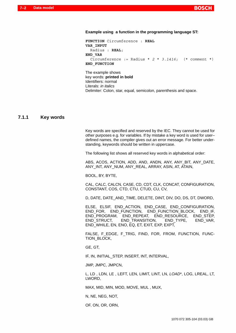
Data model7–2
1070 072 305-104 (03.03) GB
Example using a function in the programming language ST:
FUNCTION Circumference : REALVAR_INPUT Radius : REAL;END_VAR Circumference := Radius * 2 * 3.1416; (* comment *)END_FUNCTION
The example showskey words: printed in boldIdentifiers: normalLiterals: in italicsDelimiter: Colon, star, equal, semicolon, parenthesis and space.
7.1.1 Key words
Key words are specified and reserved by the IEC. They cannot be used forother purposes e.g. for variables. If by mistake a key word is used for user–defined names, the compiler gives out an error message. For better under-standing, keywords should be written in uppercase.
The following list shows all reserved key words in alphabetical order:
ABS, ACOS, ACTION, ADD, AND, ANDN, ANY, ANY_BIT, ANY_DATE,ANY_INT, ANY_NUM, ANY_REAL, ARRAY, ASIN, AT, ATAIN,
BOOL, BY, BYTE,
CAL, CALC, CALCN, CASE, CD, CDT, CLK, CONCAT, CONFIGURATION,CONSTANT, COS, CTD, CTU, CTUD, CU, CV,
D, DATE, DATE_AND_TIME, DELETE, DINT, DIV, DO, DS, DT, DWORD,
ELSE, ELSIF, END_ACTION, END_CASE, END_CONFIGURATION,END_FOR, END_FUNCTION, END_FUNCTION_BLOCK, END_IF,END_PROGRAM, END_REPEAT, END_RESOURCE, END_STEP,END_STRUCT, END_TRANSITION, END_TYPE, END_VAR,END_WHILE, EN, ENO, EQ, ET, EXIT, EXP, EXPT,
FALSE, F_EDGE, F_TRIG, FIND, FOR, FROM, FUNCTION, FUNC-TION_BLOCK,
GE, GT,
IF, IN, INITIAL_STEP, INSERT, INT, INTERVAL,
JMP, JMPC, JMPCN,
L, LD , LDN, LE , LEFT, LEN, LIMIT, LINT, LN, LOAD*, LOG, LREAL, LT,LWORD,
MAX, MID, MIN, MOD, MOVE, MUL , MUX,
N, NE, NEG, NOT,
OF, ON, OR, ORN,

Data model 7–3
1070 072 305-104 (03.03) GB
P, PRIORITY, PROGRAM, PT, PV,
Q, Q1, QU, QD,
R, RI, R_TRIG, READ_ONLY, READ_WRITE, REAL, RELEASE, REPEAT,REPLACE, RESET*, RESOURCE, RET, RETAIN, RETC, RETCN, RE-TURN, RIGHT, ROL, ROR, RS, RTC, R_EDGE,
S, S1, SD, SEL, SEMA, SET*, SHL, SHR, SIN, SINGLE, SINT, SL, SQRT,SR, ST, STEP, STN, STRING, STRUCT, SUB,
TAN, TASK, THEN, TIME, TIME_OF_DAY, TO, TOD, TOF, TON, TP, TRAN-SITION, TRUE, TYPE,
UDINT, UINT, ULINT, UNTIL, USINT,
VAR, VAR_ACCESS, VAR_EXTERNAL, VAR_GLOBAL, VAR_IN_OUT,VAR_INPUT, VAR_OUTPUT,
WHILE, WITH, WORD,
XOR, XORN.
. * The key words R, S and LD of the input parameters are used in theprogramming language instruction list (IL) with another meaning. Dueto this conflict, there are difficulties during translation by a compiler.This problem was taken up in the working group for further develop-ment of the IEC 61131-3. In a revised version of the standard, the para-meter names should be changed to SET, RESET and LOAD. WinSPSalready uses this modified form.
7.1.2 Identifiers
In comparison to keywords, identifiers are alphanumeric strings which areused by the user for variable names, POU names, constants etc. . The for-mat of an identifier is fixed by the IEC.
An identifier is a series of letters, numbers and understroke character (_)which must start either with a letter or an understroke character.
The understroke is significant in the identifiers i.e. AB_C is different fromA_BC.
Multiple understrokes following directly one after the other are not allowed.
. With the activation of WinSPS function switch /O2, the checking is tur-ned off so that multiple understrokes may be allowed to appear in thesymbolic identifiers.
As there is no difference between uppercase and lowercase letters, the iden-tifier “Hopper_Empty” is identical to “HOPPER_EMPTY” or “hopper_empty”.
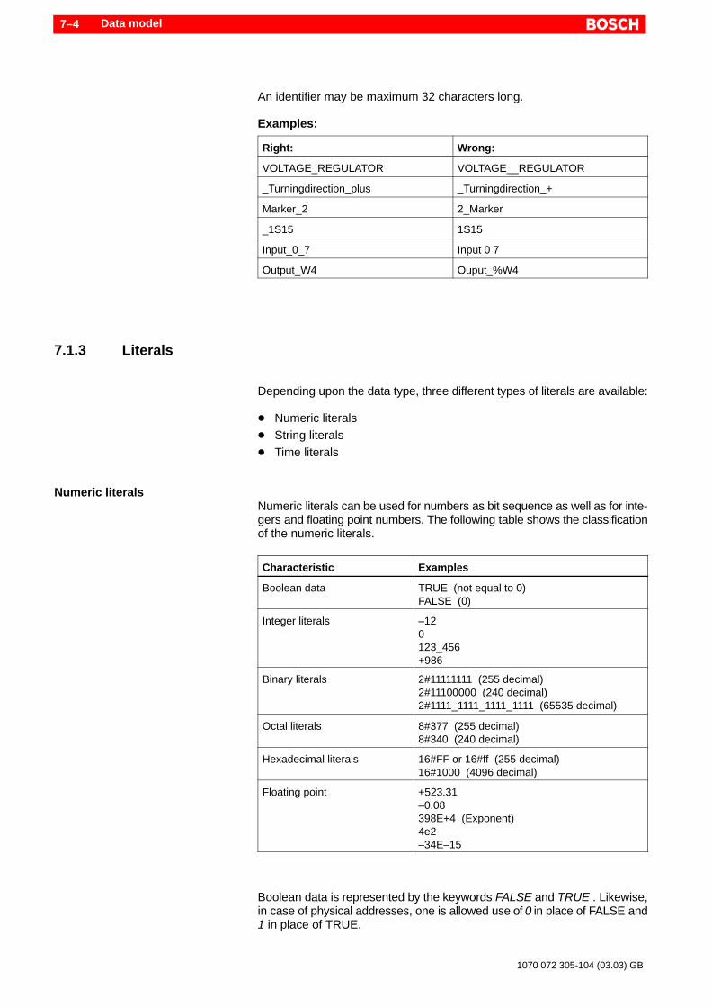
Data model7–4
1070 072 305-104 (03.03) GB
An identifier may be maximum 32 characters long.
Examples:
Right: Wrong:
VOLTAGE_REGULATOR VOLTAGE__REGULATOR
_Turningdirection_plus _Turningdirection_+
Marker_2 2_Marker
_1S15 1S15
Input_0_7 Input 0 7
Output_W4 Ouput_%W4
7.1.3 Literals
Depending upon the data type, three different types of literals are available:
D Numeric literalsD String literalsD Time literals
Numeric literalsNumeric literals can be used for numbers as bit sequence as well as for inte-gers and floating point numbers. The following table shows the classificationof the numeric literals.
Characteristic Examples
Boolean data TRUE (not equal to 0)FALSE (0)
Integer literals –120123_456+986
Binary literals 2#11111111 (255 decimal)2#11100000 (240 decimal)2#1111_1111_1111_1111 (65535 decimal)
Octal literals 8#377 (255 decimal)8#340 (240 decimal)
Hexadecimal literals 16#FF or 16#ff (255 decimal)16#1000 (4096 decimal)
Floating point +523.31–0.08398E+4 (Exponent)4e2–34E–15
Boolean data is represented by the keywords FALSE and TRUE . Likewise,in case of physical addresses, one is allowed use of 0 in place of FALSE and1 in place of TRUE.

Data model 7–5
1070 072 305-104 (03.03) GB
Decimal literals are represented in traditional style. They can have a leadingsign (+ or –). Base-specific numbers may not have any sign.
The letters A to F for the hexadecimal numbers 10 to 15 can be written inuppercase or lowercase.
Understroke characters introduced for better readability are allowed and arenot significant. Leading understroke characters are not allowed.
Floating point numbers can be written with a decimal ”.” as punctuation mark,or can be written in exponential form. Even in this case, leading signs areallowed.
String literalA string literal (earlier ASCII constant) is a sequence of zero or more charac-ters which are enclosed by single quotation marks (’).
The maximum length is manufacturer-dependent and for the Bosch control-ler, it’s value is presently 63 characters.
The string terminator ’\0’ is automatically added.
Displayable characters out of the standard ASCII character set:Hexadecimal 20 to 7F.
Characters outside this range can be represented with a leading $ sign (e.g.$80).
In addition, the IEC provides for special characters which begin with the dol-lar sign. With this, characters can be formatted for outputting on display unitsor printers.
Examples:
Character combination Explanation
$$ Single dollar sign
$’ Single quotation mark
$R or $r Carriage return (CR = $0D)
$L or $l Linefeed (LF = $0A)
$P or $p Formfeed (FF = $0C)
$N or $n New row
$T or $t Tab

Data model7–6
1070 072 305-104 (03.03) GB
. In addition to IEC 61131-3, Bosch allows direct use of umlauts.
Examples for string literals:’ABC_123’ (* Output: ABC_123 *)
’’ (* Empty string *)
’ ’ (* String of length 1, with space *)
’$’’ (* Output: ’ *)
’$R$L$0D$0A’ (* String of length 4, each with 2 CR and LF *)
’$$1.00’ (* Output: $1.00 *)
’$9Aberd$84mpfung’ (* Output: Überdämpfung *)
’Smörgåsbord’ (* allowed by Bosch ! *)
Time literalsWith the time literals, values for time duration, time and date are formed.
The IEC allows a short form for time literals.
Time type Examples Shortform
Time duration TIME#1h_15m_30s_60msTIME#14ms
T#
Time of day TIME_OF_DAY#11:36:15.20 TOD#
Calendar date DATE#2001–04–09 D#
Date and time DATE_AND_TIME#2001–04–09–11:36:15.20 DT#
The type time duration is used for processing a relative time. The other typesin comparison to this are used for absolute day of time and date.
Understroke characters introduced for better readability are allowed and arenot significant.
In case of time duration, positions, which are not relevant, may be left out. Atime duration may “overflow”.
Example of non-relevant positions and an overflow:T#80m_15s corresponds to T#1h_20m_15s (overflow) and may be writtenboth ways. As a granulation in milliseconds is not necessary in this example,the corresponding positions may be left out.

Data model 7–7
1070 072 305-104 (03.03) GB
7.1.4 Delimiter
Delimiters are special characters that are used for different purposes. Thus,colon is for example used not only for the time within the literal “time of day”but also for defining a data type name.
The following table contains all delimited characters.
Name / Function Character
Space
End Of Line (CR+LF, EOL : end of line)
Beginning of a comment (*
End of a comment *)
Plus +
Minus –
Multiplication *
Division /
Exponent as operator **
Exponent in case of floating point literal e
Hash sign #
Dollar sign $
Parenthesis ( )
Square brackets [ ]
Percentage sign %
Ampersand sign &
Quotation marks ’
Comma ,
Semicolon ;
Decimal sign .
Dot dot ..
Colon :
Assignment symbol :=
Assignment symbol for PROGRAM call =>
Prefix time literals T#, D#, TOD#, DT#TIME#,DATE#,TIME_OF_DAY#,DATE_AND_TIME#,D, H, M, S, MS
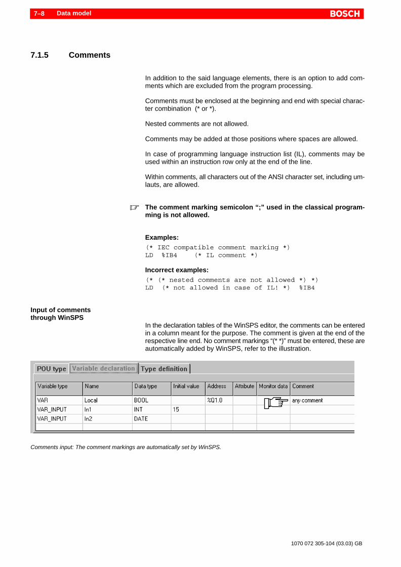
Data model7–8
1070 072 305-104 (03.03) GB
7.1.5 Comments
In addition to the said language elements, there is an option to add com-ments which are excluded from the program processing.
Comments must be enclosed at the beginning and end with special charac-ter combination (* or *).
Nested comments are not allowed.
Comments may be added at those positions where spaces are allowed.
In case of programming language instruction list (IL), comments may beused within an instruction row only at the end of the line.
Within comments, all characters out of the ANSI character set, including um-lauts, are allowed.
. The comment marking semicolon “;” used in the classical program-ming is not allowed.
Examples:(* IEC compatible comment marking *)LD %IB4 (* IL comment *)
Incorrect examples:(* (* nested comments are not allowed *) *)LD (* not allowed in case of IL! *) %IB4
Input of commentsthrough WinSPS
In the declaration tables of the WinSPS editor, the comments can be enteredin a column meant for the purpose. The comment is given at the end of therespective line end. No comment markings “(* *)” must be entered, these areautomatically added by WinSPS, refer to the illustration.
Comments input: The comment markings are automatically set by WinSPS.

Data model 7–9
1070 072 305-104 (03.03) GB
7.2 Data types
The characteristic of a variable is determined from the data type. For exam-ple, for time operations other data types are required in comparison to thedata types for floating point arithmetic.
In the IEC, the important data types have been standardized. They are refer-red to as “elementary data types” .
In addition to this, there is an option of defining the user-specific data type.These are called “derived data types” or also “type definitions”.
Another data type of the IEC is used for standard functions. These are “gene-ric data types”.
7.2.1 Elementary data types
Elementary data types are standardized in the IEC 61131-3 and are predefi-ned by keywords (e.g. BOOL, SINT, etc.).
Data types are used for the declaration of the variables, refer to section 7.3.
The initialization value of a data type is fixed in the declaration part using theassignment operator ”:=”. If no initialization value is assigned, the standardvalue defined by the IEC is assumed to be the default value, refer to the follo-wing table: Default value.
The following table shows all usable data types. In addition to this, the IECspecifies the data types LINT, ULINT and LWORD, which are not supportedby the Bosch controller.

Data model7–10
1070 072 305-104 (03.03) GB
Key word Datawidth(Bit)
Default value Explanation
BOOL 1 FALSE Logical value(not equal to 0 => TRUE, equal to 0 => FALSE).The values 0 = FALSE and 1 = TRUE may be used (ma-nufacturer-specific).
BYTE 8 0 Bit sequence of length 8 (0 to 255).
WORD 16 0 Bit sequence of length 16 (0 to 65535).
DWORD 32 0 Bit sequence of length 32 (0 to 4,294,967,295).
SINT 8 0 Short integer, figure with a sign(–128 to +127).
INT 16 0 Integer, figure with a sign(–32768 to +32767).
DINT 32 0 Double integer, figure with a sign(–2,147,483,648 to +2,147,483,647).
USINT 8 0 Unsigned short integer, figure without a sign with anadjustable figure base in the value range (0 to 255).
UINT 16 0 Unsigned short integer, figure without a sign with an ad-justable figure base in the value range (0 to 65,535).
UDINT 32 0 Unsigned double integer, figure without a sign with anadjustable number base in the value range (0 to 4,294,967,295).
REAL 32 0.0 Floating point number = Floating Point (Double word)(1,175494351e–38 to 3,402823466e+38)
LREAL 64 0.0 Floating point number = Floating Point (Quadruple word)(2,2250738585072014e–308 to1,7976931348623158e+308)
TIME 32* T#0s Time duration Input in hours (h), minutes (m), seconds(s), milliseconds (ms)
DATE 32* D#1900–01–01 Calendar date. Format: Year–Month–Day
TIME_OF_DAY 32* TOD#00:00:00 Time. Format: Hours:Minutes:Seconds(24 Hours time format)
DATE_AND_TIME 64* DT#1900–01–01–00:00:00 Date and time
STRING Variable,max. 63Character*
’’ (Empty string = ’$00’) ASCII string. Representation: Hexadecimal 20 to 7F;characters outside this range with leading $ sign (e.g.$80). The character string is enclosed on the left and theright side by a quotation mark (e.g. ’Test’). Special con-trol characters can also be entered.
* manufacturer or system dependent

Data model 7–11
1070 072 305-104 (03.03) GB
7.2.2 Derived data types (Type definition)
Derived data types – also called type definition – are user defined data typeswhich are based on the elementary data types. With type definitions, newdata types with extended or altered attributes can be generated. In additionto this, very complex data models can be realized.
Type definitions can be made locally for the current POU, or globally for theentire project, also refer to sections 5.1 and 5.5.
For local use, derived data types are defined in the declaration part of thePOU within the keywords TYPE ... END_TYPE.
Example of type definitions:TYPE Unsigned : UINT; Signed : INT := –1; ChildAge : USINT (0..17); Children : ARRAY [1..10] OF ChildAge;END_TYPE
The example shows type definitions “Unsigned” and “Signed”, which are de-rived from the elementary data types UINT or INT, resp. . The user defineddata type “Signed” moreover gets the initial value “–1”.The definition of the derived data type “ChildAge” is based on the data typeUSINT with a limited range (not supported as yet). The example of the arraydefinition definition “Children” shows that derived data types can be usedagain for the new derivations.
Other characteristicsOther characteristics can be assigned to the data types in order to generateindividual and complex data types:
D Initial valueD EnumerationD RangeD ArrayD Data structure
Initial valueAn initial value can be assigned to the derived data type using the assign-ment operator “:=”, also refer to section 7.3.2. If the assignment is missing,the standard default value of the elementary data type is used, refer to sec-tion 7.2.1.
Examples:TYPE Signed : INT := –1; InitDate : DATE := d#2000–01–01; InitStr : STRING (63) := ’< input please >’;END_TYPE
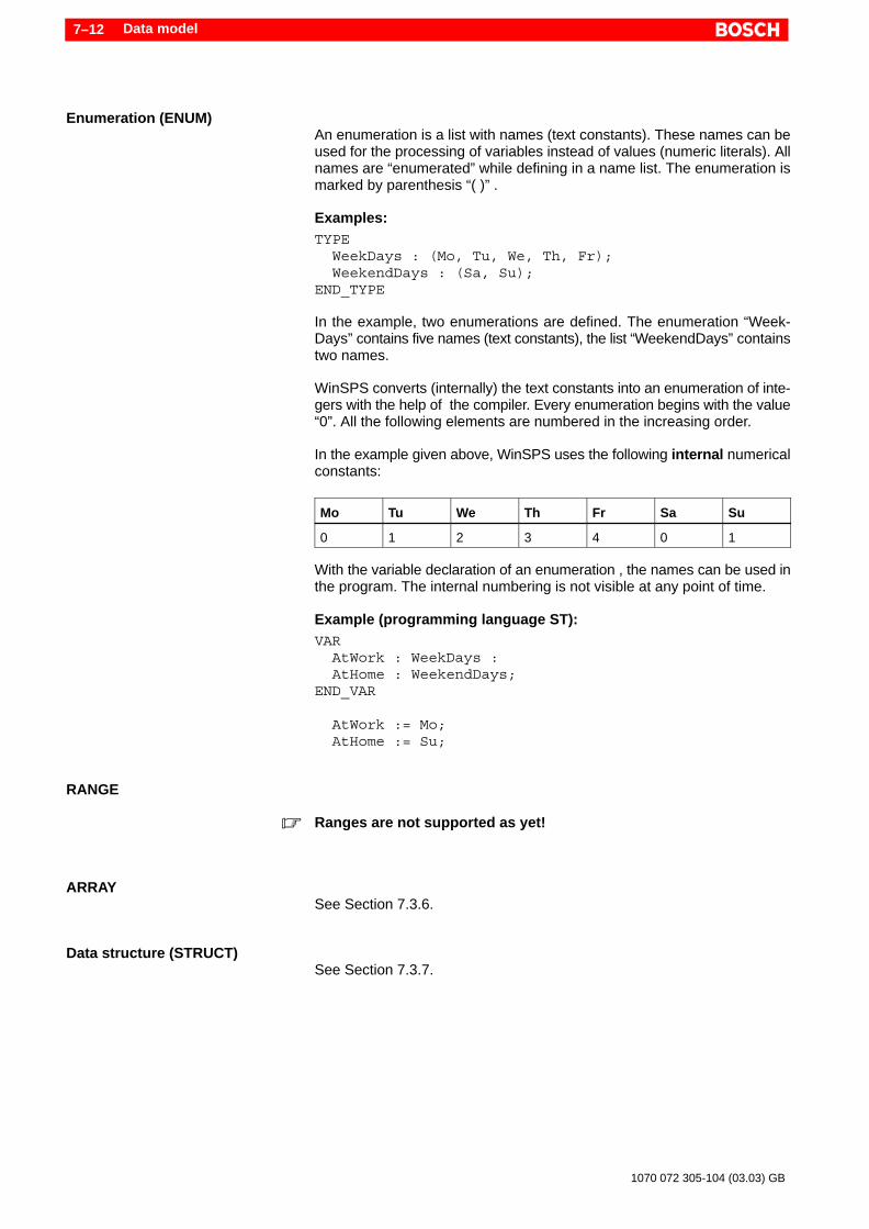
Data model7–12
1070 072 305-104 (03.03) GB
Enumeration (ENUM)An enumeration is a list with names (text constants). These names can beused for the processing of variables instead of values (numeric literals). Allnames are “enumerated” while defining in a name list. The enumeration ismarked by parenthesis “( )” .
Examples:TYPE WeekDays : (Mo, Tu, We, Th, Fr); WeekendDays : (Sa, Su);END_TYPE
In the example, two enumerations are defined. The enumeration “Week-Days” contains five names (text constants), the list “WeekendDays” containstwo names.
WinSPS converts (internally) the text constants into an enumeration of inte-gers with the help of the compiler. Every enumeration begins with the value“0”. All the following elements are numbered in the increasing order.
In the example given above, WinSPS uses the following internal numericalconstants:
Mo Tu We Th Fr Sa Su
0 1 2 3 4 0 1
With the variable declaration of an enumeration , the names can be used inthe program. The internal numbering is not visible at any point of time.
Example (programming language ST):VAR AtWork : WeekDays : AtHome : WeekendDays;END_VAR
AtWork := Mo; AtHome := Su;
RANGE
. Ranges are not supported as yet!
ARRAYSee Section 7.3.6.
Data structure (STRUCT)See Section 7.3.7.

Data model 7–13
1070 072 305-104 (03.03) GB
7.2.3 Generic data types
With the help of the generic data types, the elementary data types can beintegrated into groups. They are started with the prefix “ANY”. The followingdata types are integrated into groups.
D Signed/unsigned integer (ANY_INT)D Floating point number (ANY_REAL)D Numbers (ANY_NUM)D Bit string (ANY_BIT)D Date, time (ANY_DATE)D All above-mentioned types as well as strings, time duration and derived
data types (ANY)
With the grouping, a hierarchical order is also established. The following illu-stration shows the hierarchical levels, where the data type ANY is placed atthe highest level. The data types LINT, ULINT and LWORD are not suppor-ted by Bosch and are not specified in the illustration.
. Generic data types (ANY...) are used only for illustrative group forma-tion of elementary data types. They can not be used for the declarationof variables or for program processing. The declaration takes place in-stead through the elementary data types associated with the group,e.g. “BYTE” for the group “ANY_BIT”.
ANY
ANY_NUM ANY_BIT ANY_DATE STRING TIME DerivedData types
ANY_REAL ANY_INT BOOL DATE
SINT
TIME_OF_DAYDATE_AND_TIME
BYTEWORDDWORD
DINTUSINTUINTUDINT
INTREALLREAL
Hierarchical order of the generic data types.

Data model7–14
1070 072 305-104 (03.03) GB
Overloaded functionsThe characteristics of the generic data types are used in many standardfunctions. As a result of this, input variables of a function can not only be ap-plied for one but multiple data types. With this characteristic, they are termedas overloaded or overloadable functions, refer to section 12.1.1.
. Generic data types can be used only for standard and manufacturerfunctions. The programming of overloaded functions (user functions)is not possible.
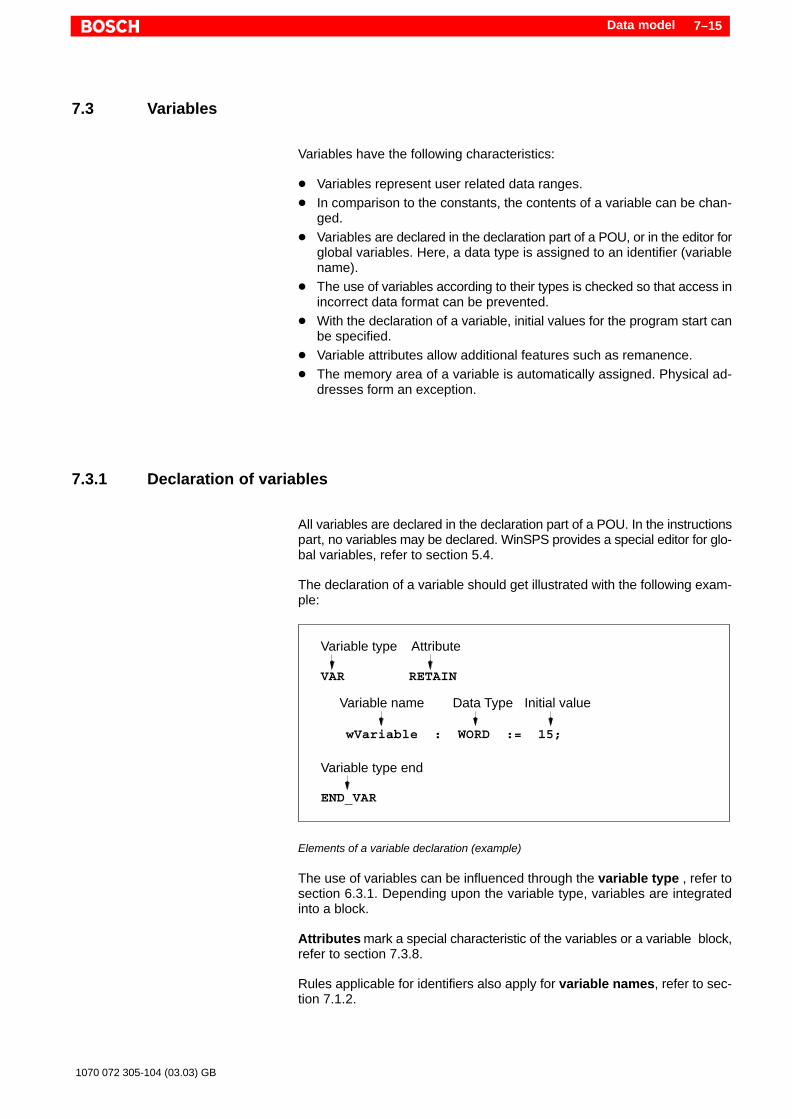
Data model 7–15
1070 072 305-104 (03.03) GB
7.3 Variables
Variables have the following characteristics:
D Variables represent user related data ranges.D In comparison to the constants, the contents of a variable can be chan-
ged.D Variables are declared in the declaration part of a POU, or in the editor for
global variables. Here, a data type is assigned to an identifier (variablename).
D The use of variables according to their types is checked so that access inincorrect data format can be prevented.
D With the declaration of a variable, initial values for the program start canbe specified.
D Variable attributes allow additional features such as remanence.D The memory area of a variable is automatically assigned. Physical ad-
dresses form an exception.
7.3.1 Declaration of variables
All variables are declared in the declaration part of a POU. In the instructionspart, no variables may be declared. WinSPS provides a special editor for glo-bal variables, refer to section 5.4.
The declaration of a variable should get illustrated with the following exam-ple:
Variable type
Variable type end
Initial value
Attribute
Data TypeVariable name
VAR RETAIN
wVariable : WORD := 15;
END_VAR
Elements of a variable declaration (example)
The use of variables can be influenced through the variable type , refer tosection 6.3.1. Depending upon the variable type, variables are integratedinto a block.
Attributes mark a special characteristic of the variables or a variable block,refer to section 7.3.8.
Rules applicable for identifiers also apply for variable names, refer to sec-tion 7.1.2.
Data model7–16
1070 072 305-104 (03.03) GB
The data type determines the characteristic of the variables, refer to section7.2.
Initial values are the starting value for the program start or for the first call tothe function or function blocks, refer to section 7.3.2.
Every declaration row is terminated with a semicolon “;”. Every variableblock is ended with “END_VAR”.
In the declaration part, any number of variable blocks may be specified. Thefrequency of same types of variables and the sequence can be anything. Incase of entries in the declaration tables, WinSPS integrates scattered varia-bles of the same variable type into one block.
While declaring an instance for function blocks, the FB name is given inplace of the data type, for structure of the structure name, also refer to sec-tion 6.6 or 7.3.7, resp. .
Examples of different variable declarations:VAR Local AT %Q1.0 : BOOL; (* Physical address *) In1 : INT := 15; (* Variable with initial value *) In2 : DATE; (* Data type: Date *) Counter : CTU; (* Instance of a FB *) Person : Person_Str; (* Decl. of a structure *) V1, V2 : WORD; (* two decl. in a row *)END_VAR
VAR_OUTPUT RETAIN Out : WORD; (* Output variable with attribute *)END_VAR
7.3.2 Initialization of variables and remanence
With the declaration of a variable using the assignment operator “:=”, an in-itial value (starting value) can be asigned. If the assignment is missing, thestandard default value of the elementary data type is used, refer to section7.2.1. Thus, variables always have specific initial values.
Examples:VAR Logical1 : BOOL := TRUE; Negative : INT := –1; InitDate : DATE := d#2000–01–01; InitStr : STRING (63) := ’< input please >’; NoInit : BOOL; (* Standard default value for data type BOOL = FALSE *)END_VAR
Variable typesInitial values may be specified in all variable types except in VAR_IN_OUTand VAR_EXTERNAL. Global variables are initialized within VAR_GLO-BAL.

Data model 7–17
1070 072 305-104 (03.03) GB
DANGERVAR_IN_OUT cannot be assigned an initial value. The initializationcan instead take place in the FB call with the specification of the cor-responding formal parameter.In case initial values are specified within the declaration ofVAR_IN_OUT, WinSPS does not generate any error message duringcompilation or linking. The initial values are however not set in thecontroller!
One-time initializationThe initial value is assigned to the variables only once. In case of declara-tions within the PROGRAM POU, the assignment takes place at the startand also during the first run of the program. Initial values, which are declaredwithin a FUNCTION_BLOCK , are assigned during the first call. As a FUNC-TION does not have a “memory”, initial values are more or less assigned withevery call.
Remanence characteristics (RETAIN)A remanence characteristic is ensured by the variable attribute RETAIN (re-fer to section 7.3.8). Remanence means that the values of a variable are re-tained after a power failure.
Moreover, remanence ranges are configured in the organization moduleOM2. Pay attention to the instructions in the software manual “PCL andCL550, Programming and Operation” (order no. 1070 072 189) or in “iPCL,System Description and Programing Manual” (order no. 1070 073 875).
. All variables are basically handled as with RETAIN attribute. Excep-tions are the standard FBs. These are basically not remanent i.e. theyare initialized after every STOP/RUN switchover.
Cold resetCold reset means : Initialization of all variables.
Cold reset is the type of start, in case of which entire variables and memoryareas are reinitialized. All variables are overwritten by the initial or defaultvalues of the data type. This process, which is also termed as restart, cantake place automatically under certain circumstances (e.g. after power fai-lure) or can even be carried out manually by the user (e.g. by pressing thereset button).
Warm startWarm start means : Initialization of the non remanent variables.
During a warm start of the controller (e.g. after a switchover STOP/RUN),the values from the last PLC cycle are restored even if initial values werespecified. The remanence characteristic thus has priority over the initial va-lues.
Restart of the PLC system and its application program at the interruptionpoint (Hot Restart) explained in the IEC 61131-3 is not supported by theBosch controller.

Data model7–18
1070 072 305-104 (03.03) GB
Startup characteristicsHere, the different starting options and the characteristics are shown:
Case 1: Program loadingProgram loading results in the initialization of all the variables (cold start).
Case 2: Stopping after error, as well as pressing the reset key (CL550)This asynchronous program break results in the initialization of all the varia-bles (cold reset).
Case 3: Switchover between STOP/RUN modeWhile changing over from STOP to RUN without changing the PLC program,the non-remanent variables are initialized (restart, warm start). The rema-nent variables retain their runtime values.
Case 4: Restart after power failure or through regular starting of thecontroller from a mains switch or “booting up” (PCL) resp.After starting the controller, the non-remanent variables are initialized (re-start, warm start). The remanent variables retain their runtime values.
Further detailed information concerning the remanence and starting charac-teristics can be found in the software manual “PCL and CL550, Program-ming and Operation” (order no. 1070 072 189) or in “iPCL, SystemDescription and Programing Manual” (order no. 1070 073 875).
7.3.3 Access to variables
The access to variables within the instructions part is dependent upon theprogramming language used. Further information can be found in the re-spective section of the programming language.

Data model 7–19
1070 072 305-104 (03.03) GB
7.3.4 Physical addresses
Physical PLC addresses are
D InputsD OutputsD Marker
. Physical addresses may be declared only within the POU of the type“PROGRAM” in the variable types “VAR” or “VAR_GLOBAL”. In thefunction block, the import through “VAR_EXTERNAL” is possible, ho-wever, not in the functions.
FormatPhysical addresses are differentiated from the other variables through prefi-xed “%” character. Subsequently follows a prefix which is specified by theIEC:
Prefix Explanation
I Input
Q Output
M Marker
With the flag for the data format following this, the data width is encrypted.The check, whether the data matches the data type, is not performed. Theaddress data following this is manufacturer-specific. In the WinSPS, twopositions – separated by a decimal – are realized.
1st Position: Byte number2nd Position: Bit number
In case of bit addresses, the bit number is specified. In case of all other dataformats, the bit addresses and the decimal are left out.
Flag Data format Width Example
X or none Bit 1 bits %IX0.0 or %I0.0
B Byte 8 bits %IB0
W Word 16 bits %QW16
D Double word 32 bits %MD4
Declaration and access
. Physical addresses must be declared.
The keyword “AT” is specified in the declaration block before the physical ad-dress and separated by a space. With this, the assignment to the physicaladdress takes place. The assignment of symbolic names is not compulsorybut recommended. As a rusult of this, physical addresses can be directlyshown or accessed through a symbolic name.

Data model7–20
1070 072 305-104 (03.03) GB
Examples (programming language ST):VAR AT %Q0.0 : BOOL; (* directly shown variable *) bIn AT %I0.1 : BOOL; (* with symbolic names *) wM4 AT %MW4 : WORD; (* marker as word operator *)END_VAR
%Q0.0 := bIn; (* access *)
The example contains the declaration of the marker word with the data typeWORD. This variable cannot be accessed by mistake with another data typesuch as DWORD or INT.
CAUTIONWinSPS manages physical addresses with the help of the symbolfile. Entries for inputs, outputs and markers are automatically takenup and the same may not be changed!
Access outside the PROGRAM POU
Outside the PROGRAM POU, physical addresses can be accessed in diffe-rent ways:
1) Through the call interface of functions and function blocks2) As global data with VAR_GLOBAL and VAR_EXTERNAL
(not allowed in case of functions)
Example concerning 1):PROGRAM XVAR AT %Q2.0 : BOOL; X1 AT %I2.0 : BOOL; ...END_VAR
FB1_Inst (Par_1:=%Q2.0, Par_2:=X1);END_PROGRAM
FUNCTION_BLOCK FB1VAR_IN_OUT Par_1 : BOOL; Par_2 : BOOL;END_VAR ...END_FUNCTION_BLOCK
The physical addresses are declared in the declaration part of the PRO-GRAM POU as local variables. During the call to the “FB1”, these addressesare assigned to the formal parameters and thus are transferred to the func-tion block. Within the “FB1”, these physical addresses are accessed usingthe names of the formal parameters “Par_1” and “Par_2”.

Data model 7–21
1070 072 305-104 (03.03) GB
Example concerning 2):PROGRAM YVAR_GLOBAL AT %Q2.0 : BOOL; X1 AT %I2.0 : BOOL;END_VAR...
FB2_Inst ();END_PROGRAM
FUNCTION_BLOCK FB2VAR_EXTERNAL %Q2.0 : BOOL; X1 : BOOL;END_VAR ...END_FUNCTION_BLOCK
Here, the physical addresses are declared as global variables. During call tothe “FB2”, they are not transferred to the function block. In the declarationpart of the “FB2”, the addresses are imported via “VAR_EXTERNAL”. As aresult of this, the variable names of the addresses do not change.
7.3.5 String variables
The data type STRING for strings allows a flexible length up to 63 charac-ters. With the declaration, a string length can be reserved. The length is gi-ven after the keyword “STRING” within the parenthesis “( )”. If there is nolength data, it is automatically set to 32. The string terminator ’\0’ is automati-cally appended and must not be included in the data concerning the stringlength.
For string variables, the rules for string literals are applicable, refer to section7.1.3.
. Please note that the string length must not be exceeded when stringsare assigned to a variable (see example below). The compiler will notdetect an exceeding. The consequence will be that other data areas ofthe SPS are overwritten during runtime.
Examples:VAR sz_8_Char : STRING(8); sz_8_Initialized : STRING(8) := ’8 characters’; sz_32_Char : STRING; (* Standard length = 32 *)
(* faulty strings because of exceeded length*) sz_Error_1 : STRING(8) := ’9 characters’; sz_Error_2 : STRING := ’This string consists of more than 32 characters’;END_VAR
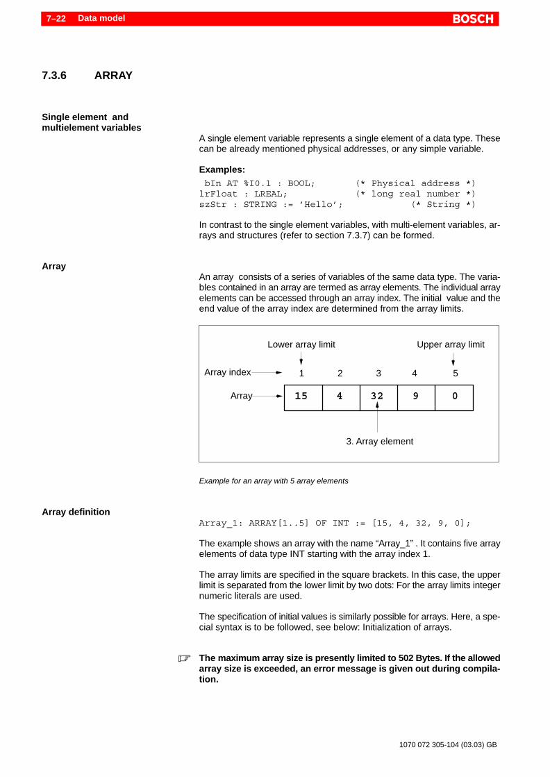
Data model7–22
1070 072 305-104 (03.03) GB
7.3.6 ARRAY
Single element and multielement variables
A single element variable represents a single element of a data type. Thesecan be already mentioned physical addresses, or any simple variable.
Examples: bIn AT %I0.1 : BOOL; (* Physical address *)lrFloat : LREAL; (* long real number *)szStr : STRING := ’Hello’; (* String *)
In contrast to the single element variables, with multi-element variables, ar-rays and structures (refer to section 7.3.7) can be formed.
ArrayAn array consists of a series of variables of the same data type. The varia-bles contained in an array are termed as array elements. The individual arrayelements can be accessed through an array index. The initial value and theend value of the array index are determined from the array limits.
Array
Array index
Lower array limit Upper array limit
3. Array element
15 4 32 9 0
1 2 3 4 5
Example for an array with 5 array elements
Array definitionArray_1: ARRAY[1..5] OF INT := [15, 4, 32, 9, 0];
The example shows an array with the name “Array_1” . It contains five arrayelements of data type INT starting with the array index 1.
The array limits are specified in the square brackets. In this case, the upperlimit is separated from the lower limit by two dots: For the array limits integernumeric literals are used.
The specification of initial values is similarly possible for arrays. Here, a spe-cial syntax is to be followed, see below: Initialization of arrays.
. The maximum array size is presently limited to 502 Bytes. If the allowedarray size is exceeded, an error message is given out during compila-tion.

Data model 7–23
1070 072 305-104 (03.03) GB
DANGERWhile accessing array elements, the array limits may not be excee-ded.Access above array limits is presently not checked and leads to un-controlled behavior!
Access to array elementsThe access in the instructions part takes place using variable names follo-wed by square brackets, in which the array index is specified.
ExamplesExample for the declaration of an arrayand access in the programming language IL:VAR aValue : ARRAY[1..5] OF SINT;
(* Array declaration *) siElement : SINT; (* Var. for test purposes *)END_VAR
LD 15 (* Array initialization *)ST aValue[1]LD 4ST aValue[2]LD 32ST aValue[3]LD 9ST aValue[4]LD aValue[5] (* contents of the 5th array
element *)
Example for access in the programming language ST: aValue[1] := 15; (* Array initialization*) aValue[2] := 4; aValue[3] := 32; aValue[4] := 9; siElement := aValue[5]; (* Contents of the 5th
array element*)
Input of arrays
Example for the entry of arrays in the declaration table .

Data model7–24
1070 072 305-104 (03.03) GB
In combination with structures, arrays are declared not inside a variableblock but in the type definition. This case is explained in detail in section7.3.7.
Mutidimensional arraysMutidimensional arrays can be created by specification of multiple commaseparated array limits.
The array elements are accessed using the comma separated array index.
Example:VAR aValue : ARRAY[1..5,0..15] OF SINT;END_VAR
aValue[1,0] := 15; (* First array element*) aValue[5,15] := 0; (* Last array element*)
The example shows a two-dimensional array. The array size can be determi-ned by multiplying the number of array elements of every dimension:
1st Dimension: [1..5] = 5 Elements2nd Dimension: [0..15] = 16 ElementsIn the example shown above, 5 * 16 = 80 measured values can be realized.
Initialization of arraysFor the initialization, the statements concerning the “Initialization of varia-bles” from section 7.3.2are applicable.
The initialization of arrays can take place using two different methods:
D Initialization during the declarationD Initialization in the instructions part at the runtime
Depending upon the application, both methods have advantages and disad-vantages:
Advantages Disadvantages
Initialization inthe declaration part
For the initialization, there isno processing time in thePLC.
Individual array elementscan be initialized with greatdifficulty in case of complexarrays.The clarity suffers.Array elements can be assi-gned only simple literals.
Initialization inthe instructions part
Complex arrays can beclearly initialized using ap-propriate algorithms.Array elements can be assi-gned extensive part expres-sions e.g. with complexcalculations.
Depending on the arraysize, the initialization at theruntime requires processingtime in the PLC.In order to avoid repeatedinitialization operations, sui-table mechanisms must beprogrammed.

Data model 7–25
1070 072 305-104 (03.03) GB
Array initializationin the declaration part
For the array initialization in the declaration part, special syntax is used. Thismust be illustrated with the help of a few examples:
Single dimensional array:Beginning with the first array element, the initial values are entered in anascending order and delimited by comma. The complete expression is enc-losed by square brackets.
aExpl1 : ARRAY[1..3] OF INT := [5,10,15];
This initialization is equivalent to the following assignment (programminglanguage ST):
aExpl1[1] := 5;aExpl1[2] := 10;aExpl1[3] := 15;
Leaving out of initial values:With the assignment, not all array elements should be initialized. The arrayelements lying at the back may be left out during initialization.
aExpl2 : ARRAY[1..3] OF INT := [5,10];
This initialization is equivalent to the following assignment:
aExpl2[1] := 5;aExpl2[2] := 10;
The last element is not initialized and as a result contains the standard de-fault value “0” of the elementary data type “INT”.
Multiplier: With the multiplier, multiple elements following after one another can be in-itialized with the same value. The multiplier is set before the parenthesis.The initial value is given inside the parenthesis.
aExpl3 : ARRAY[0..5] OF INT := [3(7),2(13),115];
In the example, the array elements are initialized as shown below:
aExpl3[0] := 7;aExpl3[1] := 7;aExpl3[2] := 7;aExpl3[3] := 13;aExpl3[4] := 13;aExpl3[5] := 115;
Data model7–26
1070 072 305-104 (03.03) GB
Moreover, a multiplier can also be used on multiple values. The values aredelimited by comma.
aExpl4 : ARRAY[0..5] OF INT := [2(7,13),2(115)];
This initialization with multiplier is equivalent to the following assignment:
aExpl4[2] := 7;aExpl4[1] := 13;aExpl4[2] := 7;aExpl4[3] := 13;aExpl4[4] := 115;aExpl4[5] := 115;
Mutidimensional arrays:In case of multidimensional arrays, there is a nesting of square brackets. Acombination [ ] is required for each dimension. Thus for example, a three di-mensional array is initialized with three nested brackets levels [ [ [ ] ] ]. Thebracket sequence is illustrated through the following example.
aExpl5 : ARRAY[1..3,1..2] OF INT :=[[1,2],[3,4],[5,6]];
In the example, the array elements are initialized as shown below:
aExpl5[1,1] := 1;aExpl5[1,2] := 2;aExpl5[2,1] := 3;aExpl5[2,2] := 4;aExpl5[3,1] := 5;aExpl5[3,2] := 6;
The multiplication factor can also be used for multidimensional arrays. In thiscase, the multiplication factor must be adjusted to the dimension range:
aExpl6 : ARRAY[1..2,1..3] OF INT := [2([3,6,9])];
This initialization is equivalent to the following assignment:
aExpl6[1,1] := 3;aExpl6[1,2] := 6;aExpl6[1,3] := 9;aExpl6[2,1] := 3;aExpl6[2,2] := 6;aExpl6[2,3] := 9;
The following example shows the complete initialization of a three dimensio-nal array. Each array element contains the value “1”:
aExpl7 : ARRAY[1..4,1..2,1..3] OF INT :=[4([2([3(1)])])];
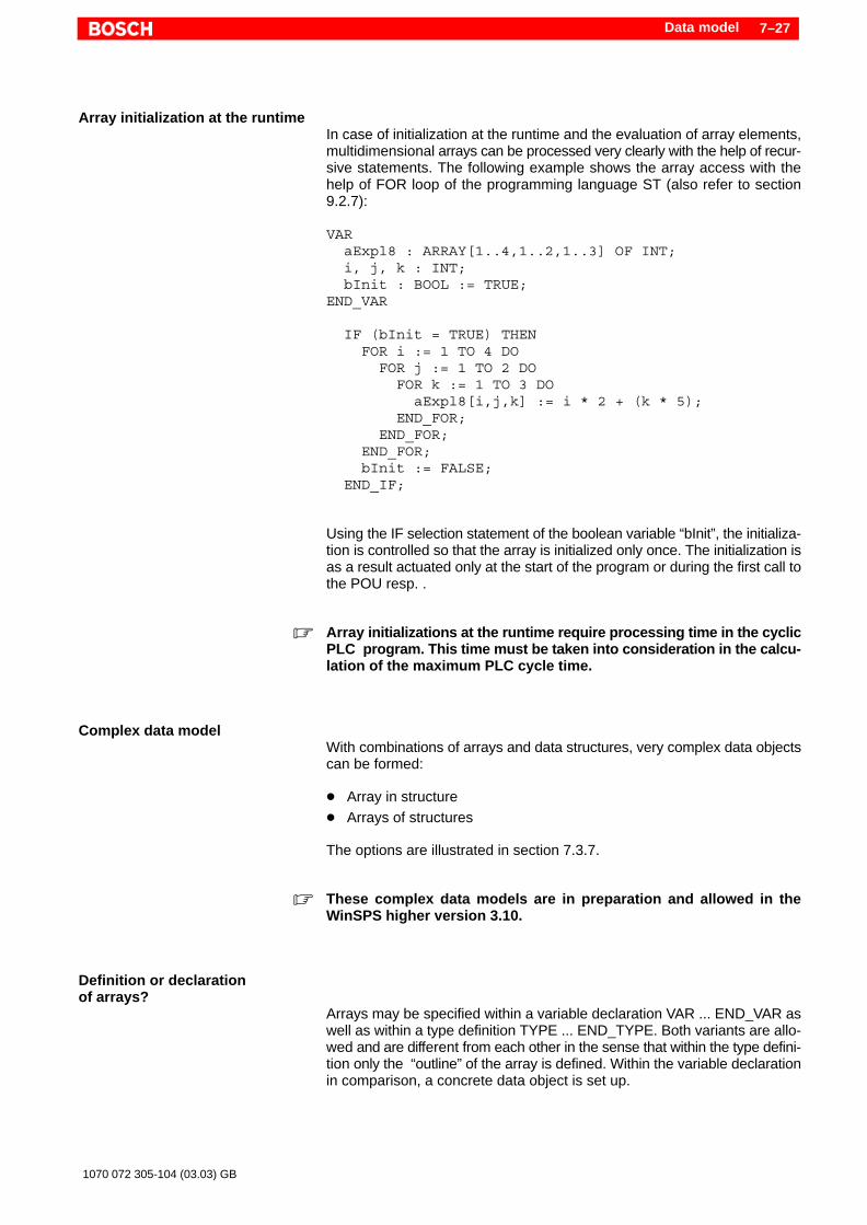
Data model 7–27
1070 072 305-104 (03.03) GB
Array initialization at the runtimeIn case of initialization at the runtime and the evaluation of array elements,multidimensional arrays can be processed very clearly with the help of recur-sive statements. The following example shows the array access with thehelp of FOR loop of the programming language ST (also refer to section9.2.7):
VAR aExpl8 : ARRAY[1..4,1..2,1..3] OF INT; i, j, k : INT; bInit : BOOL := TRUE;END_VAR
IF (bInit = TRUE) THEN FOR i := 1 TO 4 DO FOR j := 1 TO 2 DO FOR k := 1 TO 3 DO aExpl8[i,j,k] := i * 2 + (k * 5); END_FOR; END_FOR; END_FOR; bInit := FALSE; END_IF;
Using the IF selection statement of the boolean variable “bInit”, the initializa-tion is controlled so that the array is initialized only once. The initialization isas a result actuated only at the start of the program or during the first call tothe POU resp. .
. Array initializations at the runtime require processing time in the cyclicPLC program. This time must be taken into consideration in the calcu-lation of the maximum PLC cycle time.
Complex data modelWith combinations of arrays and data structures, very complex data objectscan be formed:
D Array in structureD Arrays of structures
The options are illustrated in section 7.3.7.
. These complex data models are in preparation and allowed in theWinSPS higher version 3.10.
Definition or declarationof arrays?
Arrays may be specified within a variable declaration VAR ... END_VAR aswell as within a type definition TYPE ... END_TYPE. Both variants are allo-wed and are different from each other in the sense that within the type defini-tion only the “outline” of the array is defined. Within the variable declarationin comparison, a concrete data object is set up.
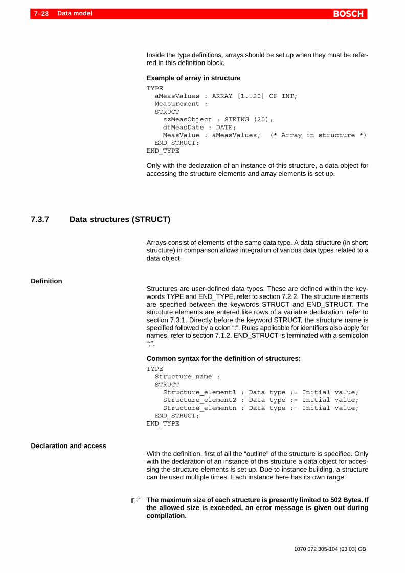
Data model7–28
1070 072 305-104 (03.03) GB
Inside the type definitions, arrays should be set up when they must be refer-red in this definition block.
Example of array in structureTYPE aMeasValues : ARRAY [1..20] OF INT; Measurement : STRUCT szMeasObject : STRING (20); dtMeasDate : DATE; MeasValue : aMeasValues; (* Array in structure *) END_STRUCT;END_TYPE
Only with the declaration of an instance of this structure, a data object foraccessing the structure elements and array elements is set up.
7.3.7 Data structures (STRUCT)
Arrays consist of elements of the same data type. A data structure (in short:structure) in comparison allows integration of various data types related to adata object.
DefinitionStructures are user-defined data types. These are defined within the key-words TYPE and END_TYPE, refer to section 7.2.2. The structure elementsare specified between the keywords STRUCT and END_STRUCT. Thestructure elements are entered like rows of a variable declaration, refer tosection 7.3.1. Directly before the keyword STRUCT, the structure name isspecified followed by a colon “:”. Rules applicable for identifiers also apply fornames, refer to section 7.1.2. END_STRUCT is terminated with a semicolon“;”.
Common syntax for the definition of structures:TYPE Structure_name : STRUCT Structure_element1 : Data type := Initial value; Structure_element2 : Data type := Initial value; Structure_elementn : Data type := Initial value; END_STRUCT;END_TYPE
Declaration and accessWith the definition, first of all the “outline” of the structure is specified. Onlywith the declaration of an instance of this structure a data object for acces-sing the structure elements is set up. Due to instance building, a structurecan be used multiple times. Each instance here has its own range.
. The maximum size of each structure is presently limited to 502 Bytes. Ifthe allowed size is exceeded, an error message is given out duringcompilation.
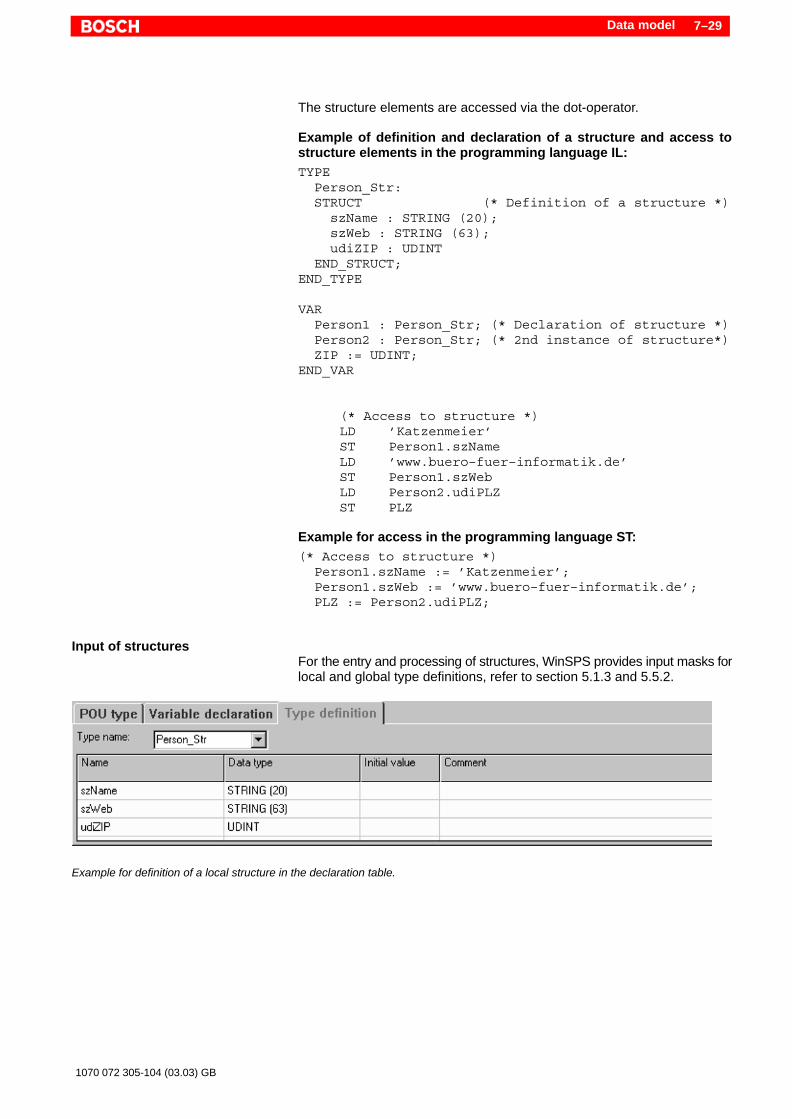
Data model 7–29
1070 072 305-104 (03.03) GB
The structure elements are accessed via the dot-operator.
Example of definition and declaration of a structure and access tostructure elements in the programming language IL:TYPE Person_Str: STRUCT (* Definition of a structure *) szName : STRING (20); szWeb : STRING (63); udiZIP : UDINT END_STRUCT;END_TYPE
VAR Person1 : Person_Str; (* Declaration of structure *) Person2 : Person_Str; (* 2nd instance of structure*) ZIP := UDINT;END_VAR
(* Access to structure *)LD ’Katzenmeier’ST Person1.szNameLD ’www.buero–fuer–informatik.de’ST Person1.szWebLD Person2.udiPLZST PLZ
Example for access in the programming language ST:(* Access to structure *) Person1.szName := ’Katzenmeier’; Person1.szWeb := ’www.buero–fuer–informatik.de’; PLZ := Person2.udiPLZ;
Input of structuresFor the entry and processing of structures, WinSPS provides input masks forlocal and global type definitions, refer to section 5.1.3 and 5.5.2.
Example for definition of a local structure in the declaration table.
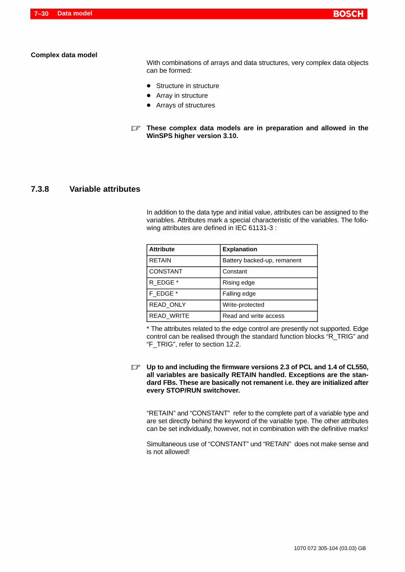
Data model7–30
1070 072 305-104 (03.03) GB
Complex data modelWith combinations of arrays and data structures, very complex data objectscan be formed:
D Structure in structureD Array in structureD Arrays of structures
. These complex data models are in preparation and allowed in theWinSPS higher version 3.10.
7.3.8 Variable attributes
In addition to the data type and initial value, attributes can be assigned to thevariables. Attributes mark a special characteristic of the variables. The follo-wing attributes are defined in IEC 61131-3 :
Attribute Explanation
RETAIN Battery backed-up, remanent
CONSTANT Constant
R_EDGE * Rising edge
F_EDGE * Falling edge
READ_ONLY Write-protected
READ_WRITE Read and write access
* The attributes related to the edge control are presently not supported. Edgecontrol can be realised through the standard function blocks “R_TRIG” and“F_TRIG”, refer to section 12.2.
. Up to and including the firmware versions 2.3 of PCL and 1.4 of CL550,all variables are basically RETAIN handled. Exceptions are the stan-dard FBs. These are basically not remanent i.e. they are initialized afterevery STOP/RUN switchover.
“RETAIN” and “CONSTANT” refer to the complete part of a variable type andare set directly behind the keyword of the variable type. The other attributescan be set individually, however, not in combination with the definitive marks!
Simultaneous use of “CONSTANT” und “RETAIN” does not make sense andis not allowed!
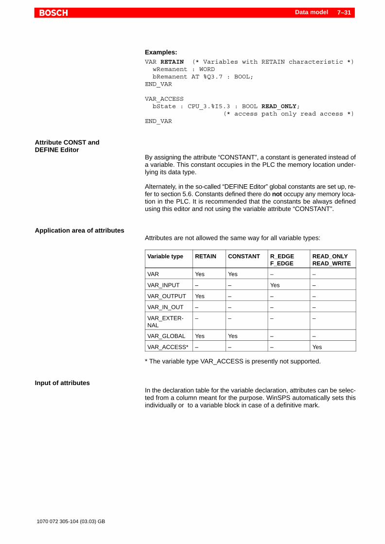
Data model 7–31
1070 072 305-104 (03.03) GB
Examples:VAR RETAIN (* Variables with RETAIN characteristic *) wRemanent : WORD bRemanent AT %Q3.7 : BOOL;END_VAR
VAR_ACCESS bState : CPU_3.%I5.3 : BOOL READ_ONLY; (* access path only read access *)END_VAR
Attribute CONST and DEFINE Editor
By assigning the attribute “CONSTANT”, a constant is generated instead ofa variable. This constant occupies in the PLC the memory location under-lying its data type.
Alternately, in the so-called “DEFINE Editor” global constants are set up, re-fer to section 5.6. Constants defined there do not occupy any memory loca-tion in the PLC. It is recommended that the constants be always definedusing this editor and not using the variable attribute “CONSTANT”.
Application area of attributesAttributes are not allowed the same way for all variable types:
Variable type RETAIN CONSTANT R_EDGEF_EDGE
READ_ONLYREAD_WRITE
VAR Yes Yes – –
VAR_INPUT – – Yes –
VAR_OUTPUT Yes – – –
VAR_IN_OUT – – – –
VAR_EXTER-NAL
– – – –
VAR_GLOBAL Yes Yes – –
VAR_ACCESS* – – – Yes
* The variable type VAR_ACCESS is presently not supported.
Input of attributesIn the declaration table for the variable declaration, attributes can be selec-ted from a column meant for the purpose. WinSPS automatically sets thisindividually or to a variable block in case of a definitive mark.

Data model7–32
1070 072 305-104 (03.03) GB
Example for the specification of attributes in the declaration table .
VAR byNone : BYTE := 16#0A;END_VAR
VAR RETAIN byBuffered : BYTE;END_VAR
VAR CONSTANT byConstant : BYTE := 16#0A;END_VAR
Illustration of the above-mentioned example in the text form
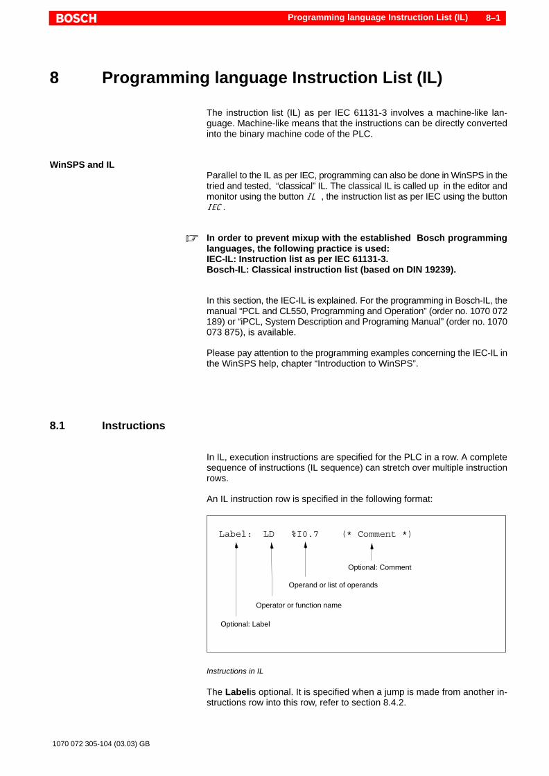
Programming language Instruction List (IL) 8–1
1070 072 305-104 (03.03) GB
8 Programming language Instruction List (IL)
The instruction list (IL) as per IEC 61131-3 involves a machine-like lan-guage. Machine-like means that the instructions can be directly convertedinto the binary machine code of the PLC.
WinSPS and ILParallel to the IL as per IEC, programming can also be done in WinSPS in thetried and tested, “classical” IL. The classical IL is called up in the editor andmonitor using the button IL , the instruction list as per IEC using the buttonIEC .
. In order to prevent mixup with the established Bosch programminglanguages, the following practice is used:IEC-IL: Instruction list as per IEC 61131-3.Bosch-IL: Classical instruction list (based on DIN 19239).
In this section, the IEC-IL is explained. For the programming in Bosch-IL, themanual “PCL and CL550, Programming and Operation” (order no. 1070 072189) or “iPCL, System Description and Programing Manual” (order no. 1070073 875), is available.
Please pay attention to the programming examples concerning the IEC-IL inthe WinSPS help, chapter “Introduction to WinSPS”.
8.1 Instructions
In IL, execution instructions are specified for the PLC in a row. A completesequence of instructions (IL sequence) can stretch over multiple instructionrows.
An IL instruction row is specified in the following format:
Label: LD %I0.7 (* Comment *)
Optional: Comment
Operand or list of operands
Operator or function name
Optional: Label
Instructions in IL
The Labelis optional. It is specified when a jump is made from another in-structions row into this row, refer to section 8.4.2.

Programming language Instruction List (IL)8–2
1070 072 305-104 (03.03) GB
At the position operator , either an IL operator or a function name is speci-fied. This describes the operation to be carried out. All possible operators arelisted in section 8.5.
There must be at least one delimiter between the operator and operand.The space or the tab can be used as delimiter.
Operands are variables or constants, using which an operation (instruction)is carried out using the operator. At the time of a function call, the operand isan input parameter. Depending upon the type of the operation or the functioncall, multiple operands can be specified as operand list delimited bycomma. For a few operators, no operand is necessary, e.g. “RET”.
In order to realise nesting, parenthesis are allowed, refer to section 8.4.3.
The label is optional. Comments may be given within an instruction row atthe end of the line. Also refer to section 7.1.5.
. The comment marking semicolon “;”used in the classical program-ming is not allowed.
8.2 Working register and status bits
Working registers (accumulators), as you find in the classical Bosch-IL ap-plication, do not exist in case of IL as per IEC 61131-3. However, there is a“virtual” working register with the name “CR ”, refer to section 8.3.
Likewise, there are no status bits, which in the Bosch-IL, indicate the condi-tions Interrupt, Carry, Overflow, Zero and Negation.
8.3 Current Result (CR) – the universal accumulator
Similar to the register for the “Result of Logic Operations” (RLO) out ofBosch-IL, the IEC-IL recognizes an accumulator with the name “CurrentResult” (CR). It is used to accept and process operands and results of thePLC instructions.
Example of an evaluation of the CR:M1: LD iOperand1
ADD iOperand2ST iResult (* calculation result *)EQ 100 (* comparison CR = 100 ? *)JMPC M2 (* ...then jump to M2 *)
In the example, the instruction EQ is used, which accesses the current result(CR). The CR contains the result of the addition generated by the instructionStore (ST). It can be used until it is reset by an operation such as LD. A list ofIL instructions which influence the CR, is shown in the following table and inthe individual instruction descriptions in section 8.5.

Programming language Instruction List (IL) 8–3
1070 072 305-104 (03.03) GB
Behaviour in case ofdifferent operators
Depending upon the operator (refer to section 8.5), the CR is influenced dif-ferently:
Influence Explanation
create The operators LD and LDN create a CR i.e.the CR is initialised with a new value.
process The instruction uses the CR of the preceding result andmodifies the same.Examples: &, OR, ADD, MUL, GT, EQ, LE.
leave unchanged The instruction uses the CR of the preceding result,however, it does not modify the same.Examples: ST, S, R, RETC
set to undefined The following instructions of a CR, which is set as un-defined, may not use the same for linking.Example: JMP, CAL
In case of certain operators, the IEC leaves open, whether the CR is proces-sed further, or must remain unchanged or must be set as undefined. A des-cription of the CR behavior of the WinSPS is given in the sub-sections ofsection 8.5.
Function callsThe CR allows itself to be used not only on a result of a instruction sequencebut also before that. In case of a function call for example, there is the optionof transferring the initial input parameters from the CR of the earlier executedinstruction without further specifications, refer to section 8.5.8.
Size and data typeIn the real sense, the accumulator is a working register in the processor ofthe PLC . However, in case of 61131-3, this accumulator is not assigned to afixed PLC memory. The CR is rather a “virtual” working register. As a result ofthis, the CR lets itself be used in a flexible manner for various data types anddata widths. The universal accumulator CR can accept the following data ty-pes:
D Generic data type, refer to section 7.2.3D Instance of a function block
. Attention must be paid to the compatibility of the data types for opera-tions following one after the other.

Programming language Instruction List (IL)8–4
1070 072 305-104 (03.03) GB
8.4 Program rules
8.4.1 IL sequences
An IL sequence starts with a load instruction (LD or LDN) and is not termina-ted until a new load instruction is used. Absolute function block calls as wellas jump and reverse jump operations form an exception. These are termina-ted on their own.
With the load instruction, the data type of the specified operand establishesthe allowed data type for the following operand in this sequence. Two opera-tions following one after the other must be type-compatible. With the help ofthe standard functions for type conversion, incompatible data types can beconverted, refer to section 12.1.3.
With the parenthesis, multiple nesting levels can be realized, refer to section8.4.3.
The following syntax graph gives an overview of the IL sequences. The orderis from the left to the right. The usage of the individual command groups isdescribed in detail in section 8.5.
ÎÎÎÎÎÎÎÎÎÎÎÎÎÎÎÎÎÎÎÎÎÎÎÎÎÎÎÎÎÎÎÎÎÎÎÎÎÎÎÎÎÎÎÎÎÎÎÎÎÎÎÎÎÎÎÎÎÎÎÎÎÎÎÎÎÎÎÎÎÎÎÎÎÎÎÎÎÎÎÎÎÎÎÎÎÎÎÎÎÎÎÎÎÎÎÎÎÎÎÎÎÎÎÎÎÎÎÎÎÎÎÎÎÎÎÎÎÎÎÎÎÎÎÎÎÎÎÎÎÎÎÎÎÎÎÎÎÎÎÎÎÎÎÎÎÎÎÎÎÎÎÎÎÎÎÎÎÎÎÎÎÎÎÎÎÎÎÎÎÎÎÎÎÎÎÎÎÎÎÎÎÎÎÎÎÎÎÎÎÎÎÎÎÎÎÎÎÎÎÎÎÎÎÎÎÎÎÎÎÎÎÎÎÎÎÎÎÎÎÎÎÎÎÎÎÎÎÎÎÎÎÎÎÎÎÎÎÎÎÎÎÎÎÎÎÎÎÎÎÎÎÎÎÎÎÎÎÎÎÎÎÎÎÎÎÎÎÎÎÎÎÎÎÎÎÎÎÎÎÎÎÎÎÎÎÎÎÎÎÎÎÎÎÎÎÎÎÎÎÎÎÎÎÎÎÎÎÎÎÎÎÎÎÎÎÎÎÎÎÎÎÎÎÎÎÎÎÎÎÎÎÎÎÎÎÎÎÎÎÎÎÎÎÎÎÎÎÎÎÎÎÎÎÎÎÎÎÎÎÎÎ
End of Line
Label Definit.
Load Comm.
Unconditional FB Call
Command w/ parenth.
Assignment
Command w/o parenth.
FU Call
Set / Reset
Jump on condition
FB Call
Return on condition
Unconditional Jump
Unconditional Return
Syntax graph for IL sequences
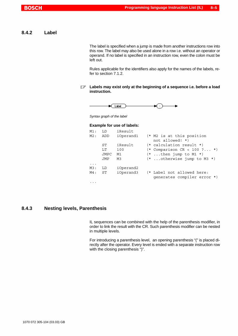
Programming language Instruction List (IL) 8–5
1070 072 305-104 (03.03) GB
8.4.2 Label
The label is specified when a jump is made from another instructions row intothis row. The label may also be used alone in a row i.e. without an operator oroperand. If no label is specified in an instruction row, even the colon must beleft out.
Rules applicable for the identifiers also apply for the names of the labels, re-fer to section 7.1.2.
. Labels may exist only at the beginning of a sequence i.e. before a loadinstruction.
ÎÎÎÎÎÎÎÎÎÎÎÎÎÎÎÎÎÎÎÎÎÎÎÎÎÎÎÎÎÎÎÎ
Syntax graph of the label
Example for use of labels:M1: LD iResultM2: ADD iOperand1 (* M2 is at this position
not allowed! *)ST iResult (* calculation result *)LT 100 (* Comparison CR < 100 ?... *)JMPC M1 (* ...then jump to M1 *)JMP M3 (* ...otherwise jump to M3 *)
...M3: LD iOperand2M4: ST iOperand3 (* Label not allowed here:
generates compiler error *)...
8.4.3 Nesting levels, Parenthesis
IL sequences can be combined with the help of the parenthesis modifier, inorder to link the result with the CR. Such parenthesis modifier can be nestedin multiple levels.
For introducing a parenthesis level, an opening parenthesis “(” is placed di-rectly after the operator. Every level is ended with a separate instruction rowwith the closing parenthesis “)”.

Programming language Instruction List (IL)8–6
1070 072 305-104 (03.03) GB
ÎÎÎÎÎÎÎÎÎÎÎÎÎÎÎÎÎÎÎÎÎÎÎÎÎÎÎÎÎÎÎÎÎÎÎÎÎÎÎÎÎÎÎÎÎÎÎÎÎÎÎÎÎÎÎÎÎÎÎÎÎÎÎÎ
Arithmetic operators
Comparison
Logical operators
Operand
Syntax graph for commands without parenthesis
ÎÎÎÎÎÎÎÎÎÎÎÎÎÎÎÎÎÎÎÎÎÎÎÎÎÎÎÎÎÎÎÎÎÎÎÎÎÎÎÎÎÎÎÎÎÎÎÎÎÎÎÎÎÎÎÎÎÎÎÎÎÎÎÎÎÎÎÎÎÎÎÎÎÎÎÎÎÎÎÎÎÎÎÎÎÎÎÎÎÎÎÎÎÎÎÎÎÎÎÎÎÎÎÎÎÎÎÎÎÎÎÎÎÎÎÎÎÎÎÎÎÎÎÎÎÎÎÎÎÎÎÎÎÎÎÎÎÎÎÎÎÎÎÎÎÎÎÎÎÎÎÎÎÎÎÎÎÎÎÎÎÎÎÎÎÎÎÎÎÎÎÎÎÎÎÎÎÎÎÎÎÎÎÎÎÎÎÎÎÎÎÎÎÎÎÎÎÎÎÎÎÎÎÎÎÎÎÎÎÎÎÎÎÎÎÎÎÎÎÎÎÎÎÎÎÎÎÎÎÎÎÎÎÎÎÎÎÎÎÎ
OperandArithmetic operators
Comparison
Logical operators Command w/ parenth.
Comm. w/o parenth.
FU Call
Assignment
Set/Reset
Syntax graph for command with parenthesis
The following table shows, for which operators a nesting level may be ope-ned, also refer to section 8.5:
Logicaloperators
Arithmeticoperators
Comparison
AND(&(ANDN(&N(OR(ORN(XOR(XORN(
ADD(SUB(MUL(DIV(
GT(GE(EQ(NE(LE(LT(
. In comparison to the programming language ST, these are no rankingof arithmetic operators in the IL . Thus for example, an addition has thesame priority during the processing as a multiplication. The proces-sing can be specified through the sequence of the instruction rowsand through parenthesis levels.
Example for multiple nesting levels:LD 5 (* 5 *)ADD( 2 (* 2 *)ADD 4 (* 6 *)MUL( 3 (* 3 *)SUB 1 (* 2 *)) (* 12 *)) (* 17 *)ST iResult (* 17 *)
The example works out the following mathematical expression:5 + ( 2 + 4 * ( 3 – 1 ) )In the comment, the current result CR is given according to the respectiveinstruction. Thus, the variable “iResult” contains the value 17.

Programming language Instruction List (IL) 8–7
1070 072 305-104 (03.03) GB
8.5 Instruction set
The following table shows a list of all IL instructions.
Modify operatorsA few operators listed in the table can be modified in order to thus widen themeaning:
N Negation of the operand:Reversing the binary signal state (from TRUE to FALSE, or from FALSE toTRUE),or complement of one for a bit pattern (every single bit is reversed).Examples: &N, LDN, ORN
C Conditional execution of the instruction:Only when the CR contains the (boolean) state TRUE is the instruction ex-ecutedExamples: JMPC, CALC
The negation and the conditional execution can be combined in case ofsome operators.Examples: JMPCN, CALCN
( Introduction of a nesting level:Example: ADD(, XOR(, GT(Options for the nesting are listed in the table in the column “(”. Further infor-mation can be found in section 8.4.3.
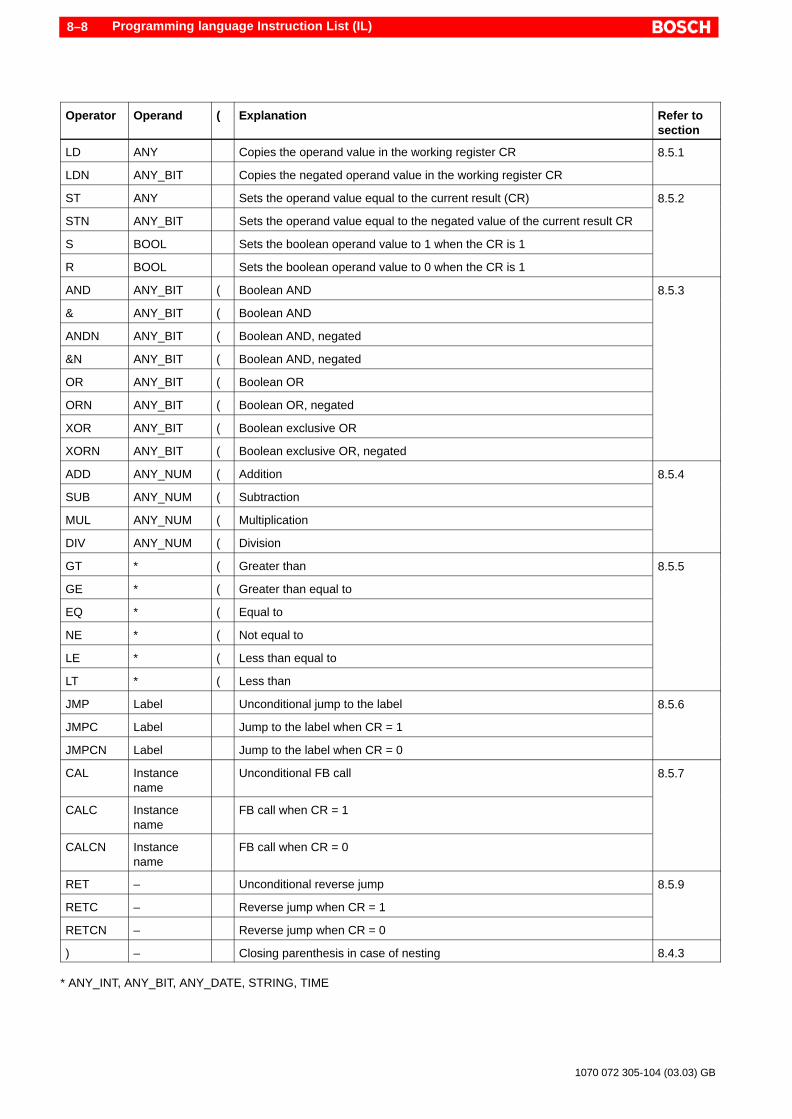
Programming language Instruction List (IL)8–8
1070 072 305-104 (03.03) GB
Operator Operand ( Explanation Refer tosection
LD ANY Copies the operand value in the working register CR 8.5.1
LDN ANY_BIT Copies the negated operand value in the working register CR
8.5.1
ST ANY Sets the operand value equal to the current result (CR) 8.5.2
STN ANY_BIT Sets the operand value equal to the negated value of the current result CR
8.5.2
S BOOL Sets the boolean operand value to 1 when the CR is 1
R BOOL Sets the boolean operand value to 0 when the CR is 1
AND ANY_BIT ( Boolean AND 8.5.3
& ANY_BIT ( Boolean AND
8.5.3
ANDN ANY_BIT ( Boolean AND, negated
&N ANY_BIT ( Boolean AND, negated
OR ANY_BIT ( Boolean OR
ORN ANY_BIT ( Boolean OR, negated
XOR ANY_BIT ( Boolean exclusive OR
XORN ANY_BIT ( Boolean exclusive OR, negated
ADD ANY_NUM ( Addition 8.5.4
SUB ANY_NUM ( Subtraction
8.5.4
MUL ANY_NUM ( Multiplication
DIV ANY_NUM ( Division
GT * ( Greater than 8.5.5
GE * ( Greater than equal to
8.5.5
EQ * ( Equal to
NE * ( Not equal to
LE * ( Less than equal to
LT * ( Less than
JMP Label Unconditional jump to the label 8.5.6
JMPC Label Jump to the label when CR = 1
8.5.6
JMPCN Label Jump to the label when CR = 0
CAL Instancename
Unconditional FB call 8.5.7
CALC Instancename
FB call when CR = 1
CALCN Instancename
FB call when CR = 0
RET – Unconditional reverse jump 8.5.9
RETC – Reverse jump when CR = 1
8.5.9
RETCN – Reverse jump when CR = 0
) – Closing parenthesis in case of nesting 8.4.3
* ANY_INT, ANY_BIT, ANY_DATE, STRING, TIME

Programming language Instruction List (IL) 8–9
1070 072 305-104 (03.03) GB
8.5.1 Load instructions – LD
ÎÎÎÎÎÎÎÎÎÎÎÎÎÎÎÎÎÎÎÎÎÎÎÎÎÎÎÎÎÎÎÎÎÎÎÎÎÎÎÎÎÎÎÎÎÎÎÎ
Syntax graph of load instructions
Loading: LDThe value of the specified operand is loaded in the working register CR. Theoriginal contents of the working register are overwritten. The operand is notchanged. The data type of the specified operand establishes the alloweddata type for the following operands in this sequence.
Allowed data types: ANY, refer to section 7.2.3.
Influencing the CR: Create, refer to section 8.3.
Examples:LD 5 (* Value 5 is loaded *)LD tod#8:27:00 (* Day time *)LD VAR_1 (* Contents of a variable *)LD %I5.7 (* directly shown
physical address *)
Negated loading: LDNThe negated value (also refer to the beginning of the section 8.5) of the spe-cified operand is loaded in the working register CR. The original contents ofthe working register are overwritten. The operand is not changed. The datatype of the specified operand specifies the allowed data type for the followingoperands in this sequence.
Allowed data types: ANY_BIT, refer to section 7.2.3.
Influencing the CR: Create, refer to section 8.3.
Example:LDN 2#01101010 (* !!! Data type ANY_BIT !!!
*)
In the example, the negated value of the operand is loaded. Thus, the CRcontains the value 2#10010101 after the execution of the instruction.

Programming language Instruction List (IL)8–10
1070 072 305-104 (03.03) GB
8.5.2 Assignments – ST, S, R
Assigning: STThe contents of the working register CR are assigned to the specified ope-rand. The original value of the operand is overwritten. The data type of thespecified operand must match with the data type of the data element in theCR. The data type of the CR is established by the data type of the variableswhich has a value assigned to it. Further assignments can then be made onlywith variables of the same data type. An assignment can be followed by an-other.
Allowed data types: ANY, refer to section 7.2.3.
Influencing the CR: Leave unchanged, refer to section 8.3.
Examples:ST VAR_1 (* Assign CR to a variable *)ST %Q5.7 (* directly shown
physical address *)
LD tod#8:27:00 (* Load time of day... *)ST todVar1 (* ...assign 2 variables *)ST todVar2
Negated assigning: STNThe negated contents (also refer to the beginning of the section 8.5) of theworking register CR is assigned to the specified operand. The original valueof the operand is overwritten. The data type of the specified operand mustmatch with the data type of the data element in the CR. The data type of theCR is established by the data type of the variables which has a value assi-gned to it. Further assignments can then be carried out only with variables ofthe same data type. Another assignment “ST” or “STN” can follow an assign-ment “STN” .
Allowed data types: ANY_BIT, refer to section 7.2.3.
Influencing the CR: Leave unchanged, refer to section 8.3.
Example:LD 2#00111100 (* !! Data type ANY_BIT !! *)STN VAR_1
In the example, the specified value is assigned to the CR using “LD”. With“STN”, the negated value 2#11000011 is assigned to the variables “VAR_1”.The CR however contains the unchanged value 2#00111100.
Set: SThe specified operand is set (TRUE) when the contents of the working regi-ster CR is equal to “1” (TRUE). The operand remains set until a reset instruc-tion reverses this state.
When this setting condition is not fulfilled, there is no change in the ope-rands.
Allowed data type: BOOL, refer to section 7.2.3.
Influencing the CR: Leave unchanged, refer to section 8.3.

Programming language Instruction List (IL) 8–11
1070 072 305-104 (03.03) GB
Examples:LD %M15.3 (* Load marker bit *)S %Q7.2 (* Set output *)
In the example, the output 7.2 is set depending upon the state of the marker15.3.
Resetting: RThe specified operand is reset (FALSE) when the contents of the workingregister CR is equal to“1” (TRUE).
When this resetting condition is not fulfilled, there is no change in the ope-rands.
Allowed data type: BOOL, refer to section 7.2.3.
Influencing the CR: Leave unchanged, refer to section 8.3.
Examples:LDN %M15.3 (* Load negated marker bit *)R %Q7.2 (* Reset output *)
In the example, the output 7.2 is set depending upon the negated state of themarker 15.3.
Example: Bistable elementsWith a combination of setting and resetting instructions, the function of a bi-stable element (flipflop) can be replicated.
The output of a bistable element can be switched by a fulfilled setting condi-tion to “1” (TRUE) or by a fulfilled resetting condition to “0” (FALSE). Thestate remains until the condition for the opposite state is fulfilled. If bothconditions are simultaneously fulfilled, the data element assumes the state,for which the condition was processed last. So, it is “set dominant” or “resetdominant”, refer to the examples:
Set dominant flipflop (SR):LD _ReSet (* Reset variable *)R _Q1 (* Reset output*)LD _Set1 (* Set variable *)S _Q1 (* Set output *)
Reset dominant flipflop (RS):LD _Set (* Set variable *)S _Q1 (* Set output *)LD _ReSet1 (* Reset variable *)R _Q1 (* Reset output*)
For bistable elements, the standard function blocks “SR” and “RS” are alsoavailable, refer to section 12.2.1.
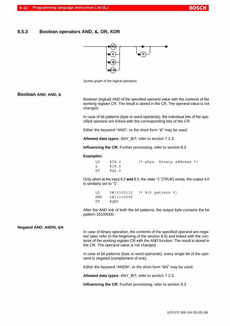
Programming language Instruction List (IL)8–12
1070 072 305-104 (03.03) GB
8.5.3 Boolean operators AND, &, OR, XOR
ÎÎÎÎÎÎÎÎÎÎÎÎÎÎÎÎÎÎÎÎÎÎÎÎÎÎÎÎÎÎÎÎÎÎÎÎÎÎÎÎÎÎÎÎÎÎÎÎÎÎÎÎÎÎÎÎÎÎÎÎÎÎÎÎÎÎÎÎÎÎÎÎÎÎÎÎÎÎÎÎÎÎÎÎÎÎÎÎÎÎSyntax graph of the logical operators
Boolean AND: AND, &Boolean (logical) AND of the specified operand value with the contents of theworking register CR. The result is stored in the CR. The operand value is notchanged.
In case of bit patterns (byte or word operands), the individual bits of the spe-cified operand are linked with the corresponding bits of the CR.
Either the keyword “AND”, or the short form “&” may be used.
Allowed data types: ANY_BIT, refer to section 7.2.3.
Influencing the CR: Further processing, refer to section 8.3.
Examples:LD %I8.2 (* phys. Binary address *)& %I8.5ST %Q4.0
Only when at the input 8.2 and 8.5, the state “1” (TRUE) exists, the output 4.0is similarly set to “1”.
LD 2#10100110 (* Bit pattern *)AND 2#11110000ST %QB0
After the AND link of both the bit patterns, the output byte contains the bitpattern 10100000.
Negated AND: ANDN, &NIn case of binary operation, the contents of the specified operand are nega-ted (also refer to the beginning of the section 8.5) and linked with the con-tents of the working register CR with the AND function. The result is stored inthe CR. The operand value is not changed.
In case of bit patterns (byte or word operands), every single bit of the ope-rand is negated (complement of one).
Either the keyword “ANDN”, or the short form “&N” may be used.
Allowed data types: ANY_BIT, refer to section 7.2.3.
Influencing the CR: Further processing, refer to section 8.3.

Programming language Instruction List (IL) 8–13
1070 072 305-104 (03.03) GB
Examples:LD %I8.2 (* phys. binary address *)&N %I8.5 (* negated state *)ST %Q4.2
The state at the input 8.5 is negated and subsequently follows the AND ope-ration with input 8.2. At the input 8.2, the state “1” (TRUE) and at the input8.5, the state “0” (FALSE) must exist so that the output 4.2 is set to “1”.
LD 2#10100110 (* Bit pattern *)ANDN 2#11110000 (* Bit pattern is negated *)ST %QB4
Negation of the second bit pattern gives rise to 2#00001111. This bit patternis linked to the first one in a binary form. The output byte contains the bit pat-tern 00000110.
Boolean OR: ORBoolean (logical) OR of the specified operand value with the contents of theworking register CR. The result is stored in the CR. The operand value is notchanged.
In case of bit patterns (byte or word operands), the corresponding bits ofevery related operand are linked.
Allowed data types: ANY_BIT, refer to section 7.2.3.
Influencing the CR: Further processing, refer to section 8.3.
Examples:LD %I8.2 (* phys. binary address *)OR %I8.5ST %Q4.1
When the state at the input 8.2 or 8.5 is set to “1” (TRUE) – even at both theinputs simultaneously, the output 4.1 is set to “1”.
LD 2#10100110 (* Bit pattern *)OR 2#11110000ST %QB8
After the OR link of both the bit patterns, the output byte contains the bit pat-tern 11110110.
Negated OR: ORNIn case of binary operation, the contents of the specified operand are nega-ted (also refer to the beginning of the section 8.5) and linked with the con-tents of the working register CR with the OR function. The result is stored inthe CR. The operand value is not changed.
In case of bit patterns (byte or word operands), every single bit of the ope-rand is negated (complement of one).
Allowed data types: ANY_BIT, refer to section 7.2.3.
Influencing the CR: Further processing, refer to section 8.3.

Programming language Instruction List (IL)8–14
1070 072 305-104 (03.03) GB
Examples:LDN %I8.2 (* phys. address negated *)ORN %I8.5 (* likewise negated *)ST %Q4.3
With the instruction LDN, the input state at 8.2 is set in the CR after negation.The state at the input 8.5, is similarly negated by the operator ORN. Subse-quently follows the OR link.
LD 2#10100110 (* Bit pattern *)ORN 2#11110000 (* Bit pattern is negated *)ST %QB12
Negation of the second bit pattern gives rise to 2#00001111. This bit patternis linked to the first one in a binary form. The output byte contains the bit pat-tern 10101111.
Exclusive OR: XORBoolean (logical) exclusive OR of the contents of the specified operand withthe contents of the working register CR. Exclusive OR means that both theoperands, which are to be linked, must be different so that the result assu-mes the state “1” (TRUE). The result is stored in the working register. Theoperand value is not changed.
In case of bit patterns (byte or word operands), the corresponding bits ofevery related operand are linked.
Allowed data types: ANY_BIT, refer to section 7.2.3.
Influencing the CR: Further processing, refer to section 8.3.
Examples:LD %I8.2 (* phys. binary address *)XOR %I8.5ST %Q4.4
The following table shows the result at the output 4.4 dependent upon theinputs:
%I8.2 FALSE TRUE FALSE TRUE
%I8.5 FALSE FALSE TRUE TRUE
%Q4.4 FALSE TRUE TRUE FALSE
LD 2#10100110 (* Bit pattern *)XOR 2#11110000ST %QB16
After the XOR link of both the bit patterns, the output byte contains the bitpattern 01010110.
Negated XOR: XORNIn case of binary links, the contents of the specified operand are negated(also refer to the beginning of the section 8.5) and linked with the contents ofthe working register CR with the XOR function. The result is stored in the CR.The operand value is not changed.

Programming language Instruction List (IL) 8–15
1070 072 305-104 (03.03) GB
In case of bit patterns (byte or word operands), every single bit of the ope-rand is negated (complement to one).
Allowed data types: ANY_BIT, refer to section 7.2.3.
Influencing the CR: Further processing, refer to section 8.3.
Examples:LD %I8.2 (* phys. binary address *)XORN %I8.5ST %Q4.5
The state at the input 8.5 is negated and subsequently follows the XOR linkwith input 8.2. The following table shows the result at the output 4.5 depen-dent upon the inputs (before the negation):
%I8.2 FALSE TRUE FALSE TRUE
%I8.5 FALSE FALSE TRUE TRUE
%Q4.5 TRUE FALSE FALSE TRUE
LD 2#10100110 (* Bit pattern *)XORN 2#11110000ST %QB20
Negation of the second bit pattern gives rise to 2#00001111. This bit patternis linked to the first one in a binary form. The output byte contains the bit pat-tern 10101001.
8.5.4 Arithmetic operators ADD, SUB, MUL, DIV
For arithmetical (mathematical) calculations, there are four types of basiccalculations available in IL i.e. addition, subtraction, multiplication and divi-sion.
ÎÎÎÎÎÎÎÎÎÎÎÎÎÎÎÎÎÎÎÎÎÎÎÎÎÎÎÎÎÎÎÎÎÎÎÎÎÎÎÎÎÎÎÎÎÎÎÎÎÎÎÎÎÎÎÎÎÎÎÎÎÎÎÎÎÎÎÎÎÎÎÎÎÎÎÎÎÎÎÎÎÎÎÎÎÎÎÎÎÎ
Syntax graph of the arithmetical operators
Addition: ADDThe specified operand value is added to the contents of the working registerCR and the result is stored in the CR. The operand value is not changed.
On the operator ADD, the opening parenthesis for the introduction of a ne-sting level can be used, refer to section 8.4.3.

Programming language Instruction List (IL)8–16
1070 072 305-104 (03.03) GB
. The function ADD for multiple addition of numeric operands and forthe addition of time values and addresses is described in section 12.1.
Allowed data types: ANY_NUM, refer to section 7.2.3.
Influencing the CR: Further processing, refer to section 8.3.
Examples:LD 24 (* Unsigned *)ADD 10ST uiVar
“uiVar” and the CR contains the value “34” after addition.
LD 78.25 (* Floating point number *)ADD –1.5 (* Unsigned *)ADD 6.75ST rVar
“rVar” and the CR contains the value “83.5” after addition. If “rVar” is an inte-ger variable (ANY_INT), it would contain the value “83”. The after decimalpositions are thus cut off.
Subtraction: SUBThe specified operand value (subtrahend) is subtracted from the contents ofthe working register CR (minuend) and the result is stored in the CR. Theoperand values are not changed.
On the operator SUB, the opening parenthesis for the introduction of a ne-sting level can be used, refer to section 8.4.3.
. The function SUB for multiple subtraction of numeric operands and forthe subtraction of time values and address is described in section 12.1.
Allowed data types: ANY_NUM, refer to section 7.2.3.
Influencing the CR: Further processing, refer to section 8.3.
Example:LD 24SUB 10ST uiVar
“uiVar” and the CR contains the value “14” after subtraction.
Multiplication: MULThe specified operand value is multiplied with the contents of the workingregister CR and the result is stored in the CR. The operand value is not chan-ged.
On the operator MUL, the opening parenthesis for the introduction of a ne-sting level can be used, refer to section 8.4.3.
Programming language Instruction List (IL) 8–17
1070 072 305-104 (03.03) GB
. The function MUL for multiple multiplication of numeric operands andfor the multiplication of time values and address is described in sec-tion 12.1.
Allowed data types: ANY_NUM, refer to section 7.2.3.
Influencing the CR: Further processing, refer to section 8.3.
Example:LD 24 (* Unsigned *)MUL 20ST uiVar
“uiVar” and the CR contains the value “480” after multiplication . The variable“uiVar” may not be of data type “SINT” or “USINT” as this cannot store theresult. Instead, a data type with larger data width must be selected, e.g.“UINT”.
Division: DIVThe contents of the working register CR (dividend) are divided by the valueof the specified operands (divisor) and the result (quotient) is stored in theCR. The operand value is not changed.
On the operator DIV, the opening parenthesis for the introduction of a ne-sting level can be used, refer to section 8.4.3.
. The function DIV for multiple division of numeric operands and for thedivision of time values and address is described in section 12.1.
Allowed data types: ANY_NUM, refer to section 7.2.3.
Influencing the CR: Further processing, refer to section 8.3.
Example:LD 24 (* Unsigned *)DIV 10ST iVar
If “iVar” is a real variable (ANY_REAL), “iVar” and the CR contain after thedivision a value of ” 2.4”. In case of an interger variable (ANY_INT), the valuewould be “2”. The after decimal positions are thus cut off.

Programming language Instruction List (IL)8–18
1070 072 305-104 (03.03) GB
8.5.5 Comparison operators– GT, GE, EQ, LE, LT, NE
With the help of boolean checks of operators, i.e. checking whether a condi-tion is met (TRUE) or not (FALSE), the program execution can be controlled.The comparison operators are e.g. combined with jump or call operators, re-fer to sections 8.5.6 and 8.5.7.
ÎÎÎÎÎÎÎÎÎÎÎÎÎÎÎÎÎÎÎÎÎÎÎÎÎÎÎÎÎÎÎÎÎÎÎÎÎÎÎÎÎÎÎÎÎÎÎÎÎÎÎÎÎÎÎÎÎÎÎÎÎÎÎÎÎÎÎÎÎÎÎÎÎÎÎÎÎÎÎÎÎÎÎÎÎÎÎÎÎÎÎÎÎÎÎÎÎÎÎÎÎÎÎÎÎÎÎÎÎÎÎÎÎÎÎÎÎÎÎÎÎÎÎÎÎÎÎÎÎÎÎÎÎÎÎSyntax graph of the comparison operators
The following comparison operators are available:
GT greater thanGE greater than or equalEQ equal toLE less than or equalLT less thanNE not equal
The specified operand value is compared with the contents of the workingregister CR. The operand value was subtracted from the value of the workingregister. The satisfied condition is indicated through the boolean state TRUEin the CR; FALSE signals that the condition was not fulfilled. The originalcontents of the CR are overwritten. The operand value is not changed.
During the comparison, a type conversion of the working register CR takesplace: After the comparison, the CR is of the data type BOOL.
The boolean result of a comparison operation can be used as condition for afunction block-call, a jump to a label, other logical linking operations or for areverse jump out of a POU to the higher-level structure level.
Allowed data types: ANY_INT, ANY_BIT, ANY_DATE, STRING, TIME, re-fer to section 7.2.3.
Influencing the CR: Further processing, refer to section 8.3.
Example:M1: LD iResult
ADD iOperand1ST iResult (* calculation result *)LE 100 (* Comparison CR <= 100... *)JMPC M1 (* ...then jump to M1 *)JMP M3 (* ...otherwise jump to M3 *)
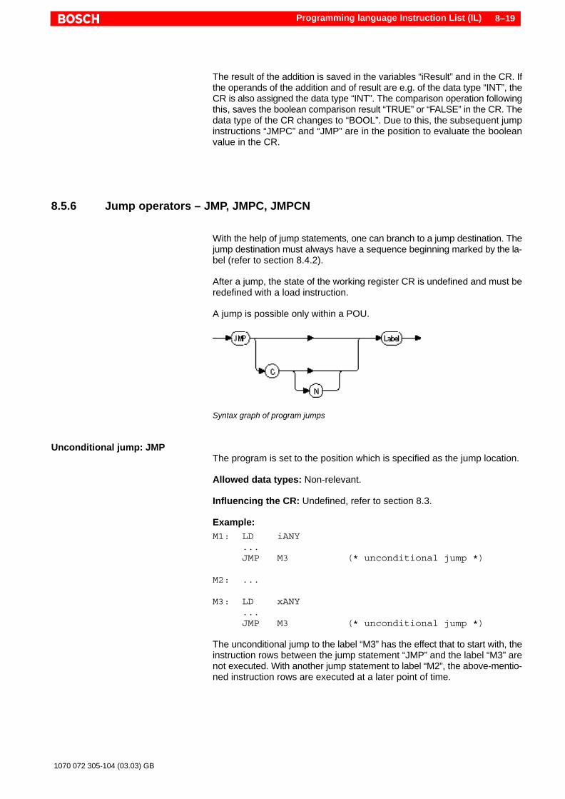
Programming language Instruction List (IL) 8–19
1070 072 305-104 (03.03) GB
The result of the addition is saved in the variables “iResult” and in the CR. Ifthe operands of the addition and of result are e.g. of the data type “INT”, theCR is also assigned the data type “INT”. The comparison operation followingthis, saves the boolean comparison result “TRUE” or “FALSE” in the CR. Thedata type of the CR changes to “BOOL”. Due to this, the subsequent jumpinstructions “JMPC” and “JMP” are in the position to evaluate the booleanvalue in the CR.
8.5.6 Jump operators – JMP, JMPC, JMPCN
With the help of jump statements, one can branch to a jump destination. Thejump destination must always have a sequence beginning marked by the la-bel (refer to section 8.4.2).
After a jump, the state of the working register CR is undefined and must beredefined with a load instruction.
A jump is possible only within a POU.
ÎÎÎÎÎÎÎÎÎÎÎÎÎÎÎÎÎÎÎÎÎÎÎÎÎÎÎÎÎÎÎÎÎÎÎÎÎÎÎÎÎÎÎÎÎÎÎÎÎÎÎÎÎÎÎÎÎÎÎÎÎÎÎÎÎÎÎÎÎÎÎÎÎÎÎÎÎÎÎÎÎÎÎÎÎÎÎÎÎÎ
Syntax graph of program jumps
Unconditional jump: JMPThe program is set to the position which is specified as the jump location.
Allowed data types: Non-relevant.
Influencing the CR: Undefined, refer to section 8.3.
Example:M1: LD iANY
...JMP M3 (* unconditional jump *)
M2: ...
M3: LD xANY...JMP M3 (* unconditional jump *)
The unconditional jump to the label “M3” has the effect that to start with, theinstruction rows between the jump statement “JMP” and the label “M3” arenot executed. With another jump statement to label “M2”, the above-mentio-ned instruction rows are executed at a later point of time.
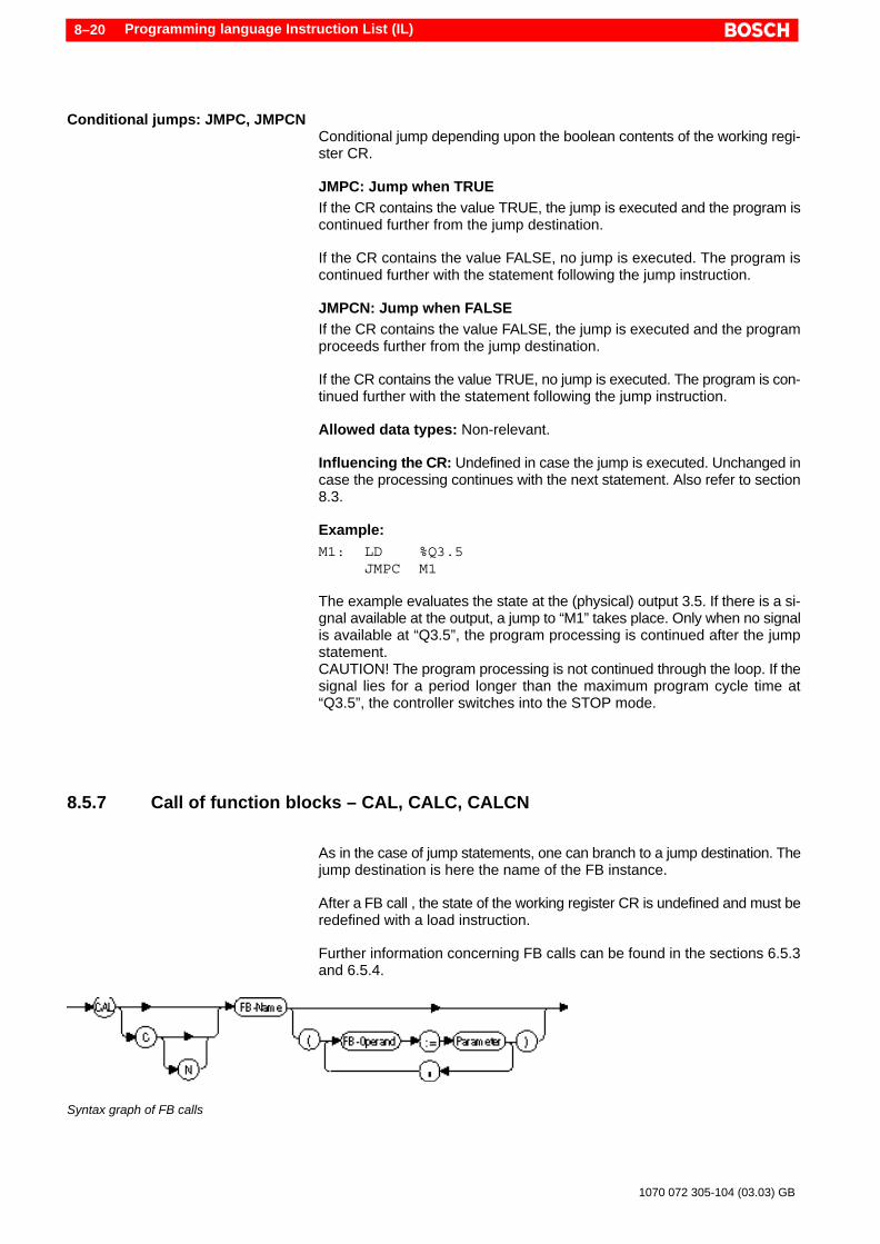
Programming language Instruction List (IL)8–20
1070 072 305-104 (03.03) GB
Conditional jumps: JMPC, JMPCNConditional jump depending upon the boolean contents of the working regi-ster CR.
JMPC: Jump when TRUEIf the CR contains the value TRUE, the jump is executed and the program iscontinued further from the jump destination.
If the CR contains the value FALSE, no jump is executed. The program iscontinued further with the statement following the jump instruction.
JMPCN: Jump when FALSEIf the CR contains the value FALSE, the jump is executed and the programproceeds further from the jump destination.
If the CR contains the value TRUE, no jump is executed. The program is con-tinued further with the statement following the jump instruction.
Allowed data types: Non-relevant.
Influencing the CR: Undefined in case the jump is executed. Unchanged incase the processing continues with the next statement. Also refer to section8.3.
Example:M1: LD %Q3.5
JMPC M1
The example evaluates the state at the (physical) output 3.5. If there is a si-gnal available at the output, a jump to “M1” takes place. Only when no signalis available at “Q3.5”, the program processing is continued after the jumpstatement.CAUTION! The program processing is not continued through the loop. If thesignal lies for a period longer than the maximum program cycle time at“Q3.5”, the controller switches into the STOP mode.
8.5.7 Call of function blocks – CAL, CALC, CALCN
As in the case of jump statements, one can branch to a jump destination. Thejump destination is here the name of the FB instance.
After a FB call , the state of the working register CR is undefined and must beredefined with a load instruction.
Further information concerning FB calls can be found in the sections 6.5.3and 6.5.4.
ÎÎÎÎÎÎÎÎÎÎÎÎÎÎÎÎÎÎÎÎÎÎÎÎÎÎÎÎÎÎÎÎÎÎÎÎÎÎÎÎÎÎÎÎÎÎÎÎÎÎÎÎÎÎÎÎÎÎÎÎÎÎÎÎÎÎÎÎÎÎÎÎÎÎÎÎÎÎÎÎÎÎÎÎÎÎÎÎÎÎÎÎÎÎÎÎÎÎÎÎÎÎÎÎÎÎÎÎÎÎÎÎÎÎÎÎÎÎÎÎ
Syntax graph of FB calls

Programming language Instruction List (IL) 8–21
1070 072 305-104 (03.03) GB
Unconditional calls: CALThe program is continued further in the function block which is specified asoperand. The unconditional call may be programmed only after completionof an IL sequence and is not allowed within the parenthesis modifiers.
Allowed data types: Non-relevant.
Influencing the CR: Undefined, refer to section 8.3.
The input parameters of the function block can be “given” with the call in theparenthesis – by separating the parameters with commas. The actual para-meters are assigned using “:=” to the formal parameters.
The second method for the parameter transfer is the initialization before thecall by a combination of load (LD) and assignment statements (ST). In caseof these methods, the FB call takes place without parenthesis.
Example, method 1:CAL CTU_1 (RESET:=%IX3.6, PV:=Limit, CU:=_1S2)
Example, method 2:LD %IX3.6ST CTU_1.RESETLDN LimitST CTU_1.PVLD _1S2ST CTU_1.CUCAL CTU_1
Conditional call: CALC, CALCNConditional FB call depending upon the boolean contents of the working re-gister CR.
CALC: Call when TRUEIf the CR contains the value TRUE, the as operand specified FB (instance) iscalled up, in which the program processing will be continued.
If the CR contains the value FALSE, no call is executed. The program is con-tinued further with the statement following the call instruction.
CALCN: Call when FALSEIf the CR contains the value FALSE, the as operand specified FB (instance)is called up, in which the program processing will be continued.
If the CR contains the value TRUE, no call is executed. The program is conti-nued further with the statement following the call instruction.
Allowed data types: Non-relevant.
Influencing the CR: Undefined in case the call is executed. Unchanged incase the processing continues with the next statement. Also refer to section8.3.

Programming language Instruction List (IL)8–22
1070 072 305-104 (03.03) GB
Example:LD bCounterResetCALCN CTU_2 (RESET:=%IX3.2, PV:=Limit, CU:=_5S1)
In the example, the FB instance “CTU_2” may only be called up when theboolean variable “bCounterReset” contains the value “FALSE”.
8.5.8 Call of functions
Allowed data types: Non-relevant.
Influencing the CR: Further processing, refer to section 8.3. The CR is oc-cupied with the function value in the function.
Unconditional callFunctions are called up without specify an operator. The input parametersare transferred directly. Due to this, no conditional calls can be implemented.
An option allows to transfer the initial input parameters from the CR of theearlier executed instruction without further specifications.
Example for the use of the CR for the first parameter in case of a func-tion call:
LD 2#10010110 (* 1st Param. is loaded into the CR *)
SHL 2 (* 2nd Param. in the call *)ST Links (* Function value in the CR *)
In the example, the function SHL is called up. The first parameter is transfer-red without assignment but only with the load instruction (LD) – with the helpof the CR. The second parameter is specified directly in the function call. Thefunction value (return value of the function) is written by the function in theCR. Thus, the function value can be used directly after the instruction row ofthe function call.
Function valueThe return value of the function (function value) is written after the functioncall in the CR for further processing.
Within the called function, the return value is generated by writing the CR tothe function name.
Example:ST FUN_Name
Formal parameterIn contrast to the programming language ST, formal parameters may basi-cally not be specified in the call. Here, the order of the input parameters mustdefinitely followed.
Further information concerning function calls can be found in the sections6.5.3 and 6.5.5.

Programming language Instruction List (IL) 8–23
1070 072 305-104 (03.03) GB
ExamplesExample 1:
LD szString (* String variable *)MID 3, 2 (* Function call +
Parameters *)ST szNew (* CR = Function value *)
In the example, the standard function “MID” (refer to section 12.1) is calledup. This function requires three input parameters. The first parameter is writ-ten with the load instruction “LD” in the CR. The other two parameters arespecified – delimited by comma – after the function call. After the functioncall, the function value from the CR is assigned to the variable “szNew” usingthe instruction “ST”.
Example 2:MID szString, 3, 2ST szNew
This variation shows the same function call as in example 1, with the diffe-rence that here, all three parameters are transferred in the call.
8.5.9 Return jump – RET, RETC, RETCN
The return jump instructions result in a return to the calling POU. With thereturn jump to a POU, the calling POU is continued at the interrupted posi-tion.
After a return jump, the state of the working register CR remains unchanged.
ÎÎÎÎÎÎÎÎÎÎÎÎÎÎÎÎÎÎÎÎÎÎÎÎÎÎÎÎÎÎÎÎÎÎÎÎÎÎÎÎÎÎÎÎÎÎÎÎÎÎÎÎÎÎÎÎÎÎÎÎÎÎÎÎÎÎÎÎÎÎÎÎÎÎÎ
Syntax graph of return jumps
Unconditional return jump: RETThe instruction “RET” results in an unconditional return jump to the callingPOU. In case of functions, the current function value is entered in the CR.
Allowed data types: No operand available.
Influencing the CR:Return jump out of function block: Leave unchanged.Return jump out of function: The current function value is stored in the CR.Also refer to section 8.3.
Example:LD bErrorJMPCN M4RET (* unconditional return *)
M4:

Programming language Instruction List (IL)8–24
1070 072 305-104 (03.03) GB
The example contains an extract from a function or a function block. If thevariable “bError” contains the boolean value “FALSE”, the program proces-sing is continued from the label “M4”. In case “bError” contains the value“TRUE”, the return jump to the calling POU follows. The same example canalso be realized differently with the help of a conditional return jump, refer tothe example below.
Conditional return jump:RETC, RETCN
Conditional return jump depending upon the boolean contents of the wor-king register CR.
RETC: Return when TRUEIf the CR contains the value TRUE, the return jump to the higher-level POUfollows.
If the CR contains the value FALSE, no return jump is executed. The pro-gram is continued further with the statement following the return jump in-struction.
RETCN: Return when FALSEIf the CR contains the value FALSE, the return jump to the higher-level POUfollows.
If the CR contains the value TRUE, no return jump is executed. The programis continued further with the statement following the reverse jump instruc-tion.
Allowed data types: No operand available.
Influencing the CR: Leave unchanged, refer to section 8.3.In comparison to the unconditional return jump “RET”, in case of a conditio-nal returns of a function, the CR is not overwritten by the function value!
Example:LD bErrorRETC
In the example, the boolean variable “bError” is evaluated. In case “bError”contains the value “TRUE” , the return to the calling POU follows. Should thevariable “bError” contain the boolean value “FALSE”, the program proces-sing is continued after the statement “RETC”.

Programming language Structured Text (ST) 9–1
1070 072 305-104 (03.03) GB
9 Programming language Structured Text (ST)
The Structured Text (ST) is a textual higher programming language. In com-parison to machine-like IL, ST is a programming language, in which exten-sive language constructs allow a very compact formulation of theprogramming task.
An ST program consists of instructions. In an instruction values are compu-ted and assigned, modules are called up and leaved, and command flow iscontrolled.
ST offers the advantage of implementing an open program structure. Thedisadvantage of this language lies in its lower efficiency. The programs areslower and longer.
Please pay attention to the programming examples concerning the ST in theWinSPS help, chapter “Introducing WinSPS”.
9.1 Expressions, operands and operators
As already mentioned, an ST program consists of instructions. An instructioncontains an expression (partial instruction), using which a result is built.Here, complex links can be generated with the help of operands and opera-tors.
OperandsAll possible operands are listed in the following table:
Operand Examples
Literalsrefer to section 7.1.3
15’ABC’t#5m_15s
Variablesrefer to section 7.3
Valve_1aMeasValue[1,0]Person.szName
Function callsrefer to section 6.5.5
LEN ( CONCAT (’to’, ’ gether’ ))
OperatorsThe operands can be linked to each other through operators. The followingtable shows all operators of the programming language ST. The precedenceduring the processing is shown in the decreasing order of precedence; i.e.the “Parenthesis” have the highestpriority. If an expression has more thanone operator, the order of precedence is to be taken into account. Operatorswith higher priority are processed before the operators with lower priority. Incase of equal priority, the processing takes place from left to right.

Programming language Structured Text (ST)9–2
1070 072 305-104 (03.03) GB
Operator Explanation Example
( ) Parenthesis (2+3)*(4+4)Result: 40Without parenthesis: 18
Function call CONCAT(’TO’,’GETHER’)Result: ’TOGETHER’
** Exponentiation 2**3Result: 8
– Negation –12Result: –12
NOT Complement NOT FALSEResult: TRUE
* Multiplication 3 * 4Result: 12
/ Division 12 / 6Result: 2
MOD Modulo(Remainder of a division)
23 MOD 6Result: 5
+ Addition 3 + 5Result: 8
– Subtraction 5 – 7Result: –2
<><=>=
Comparison: Less thanGreater thanLess than or equalGreater than or equal
45 > 66Result: FALSE
= Equality T#34h = T#6d7hResult: FALSE
<> Inequality 10 <> 16#AResult: FALSE
&AND
Boolean AND TRUE AND FALSEResult: FALSE
XOR Boolean Exclusive OR TRUE XOR FALSEResult: TRUE
OR Boolean OR TRUE OR FALSEResult: TRUE
Function calls as operatorsCalls of function blocks represent a closed instruction, refer to section 9.2. Incontrast to that, functions (FUN) are called up within a partial instruction andare counted among the expressions. Further information and examples con-cerning function calls can be found in section 6.5.5.
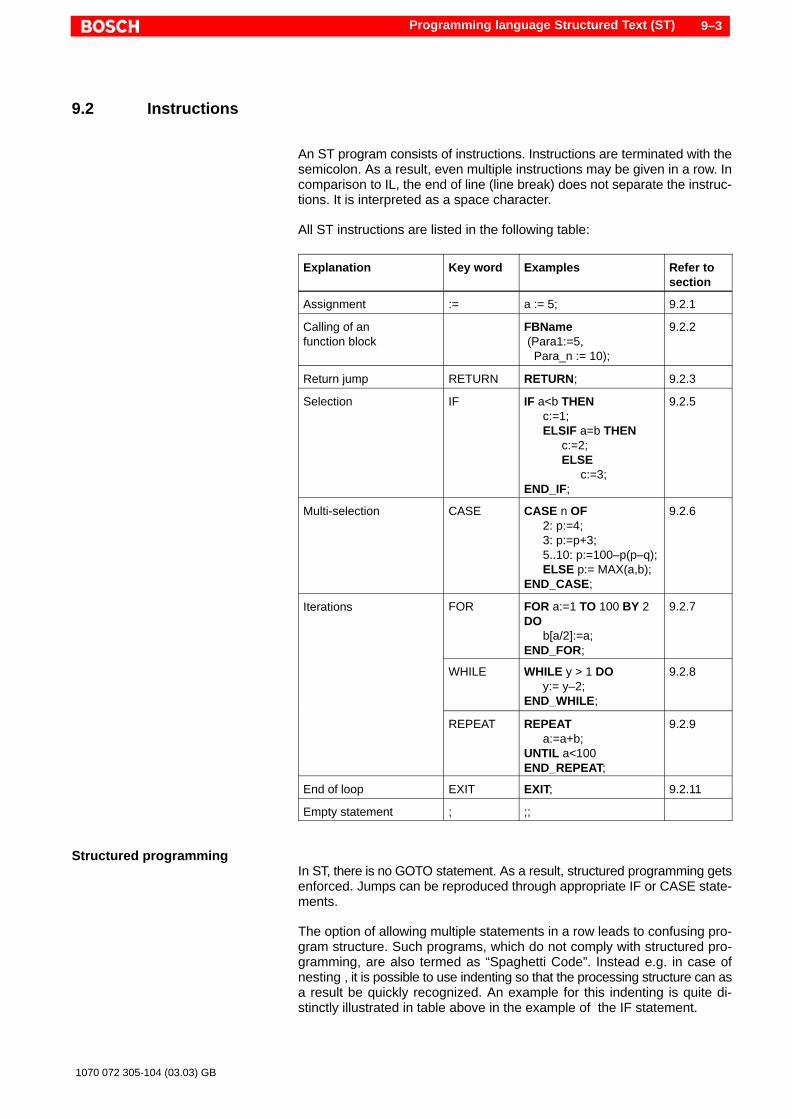
Programming language Structured Text (ST) 9–3
1070 072 305-104 (03.03) GB
9.2 Instructions
An ST program consists of instructions. Instructions are terminated with thesemicolon. As a result, even multiple instructions may be given in a row. Incomparison to IL, the end of line (line break) does not separate the instruc-tions. It is interpreted as a space character.
All ST instructions are listed in the following table:
Explanation Key word Examples Refer tosection
Assignment := a := 5; 9.2.1
Calling of anfunction block
FBName (Para1:=5, Para_n := 10);
9.2.2
Return jump RETURN RETURN; 9.2.3
Selection IF IF a<b THENc:=1;
ELSIF a=b THEN c:=2; ELSE c:=3;END_IF;
9.2.5
Multi-selection CASE CASE n OF2: p:=4;3: p:=p+3;5..10: p:=100–p(p–q);ELSE p:= MAX(a,b);
END_CASE;
9.2.6
Iterations FOR FOR a:=1 TO 100 BY 2DO
b[a/2]:=a;END_FOR;
9.2.7
WHILE WHILE y > 1 DOy:= y–2;
END_WHILE;
9.2.8
REPEAT REPEATa:=a+b;
UNTIL a<100END_REPEAT;
9.2.9
End of loop EXIT EXIT; 9.2.11
Empty statement ; ;;
Structured programmingIn ST, there is no GOTO statement. As a result, structured programming getsenforced. Jumps can be reproduced through appropriate IF or CASE state-ments.
The option of allowing multiple statements in a row leads to confusing pro-gram structure. Such programs, which do not comply with structured pro-gramming, are also termed as “Spaghetti Code”. Instead e.g. in case ofnesting , it is possible to use indenting so that the processing structure can asa result be quickly recognized. An example for this indenting is quite di-stinctly illustrated in table above in the example of the IF statement.

Programming language Structured Text (ST)9–4
1070 072 305-104 (03.03) GB
9.2.1 Assignment
An assignment transfers the result of the evaluation of an expression to avariable. The assignment copies the value existing on the right side of theequivalence sign ’:=’ into the variable on the left side.
In the assignments, single element as well as multiple element variables canbe used.
Examples:(* Assignment: Variable a is assigned the value 5 *)a := 5;
(* Two assignments in one row *)b[1] := a**2; d := b[2];
(* Assignment with a function call *)d := REAL_TO_INT (c);
. The variable on the left side must be of the same type as the currentlyassigned value.
. In case of an assignment, do not forget to enter a colon before theequivalence sign “:=”. A standalone equivalence sign “=” is used forcomparison operations.
9.2.2 Call of an function block
In ST, a function block (FB) is called up using its name and its formal parame-ters existing in the parenthesis. In this case, the sequence is not significant.The value of the actual parameters is assigned to the formal parameters.Output parameters can similarly be assigned to the formal parameters in thecall. Input and output parameters are then separated from each other withthe character ”|”. The assignment can take place directly in the call throughcorresponding statements.
While calling up a function block, not necessary parameters may be left out.
. VAR_IN_OUT parameters may not be left out. During compilation,WinSPS generates an error message in case VAR_IN_OUT parametersare left out.
Detailed information concerning the call up interface of FBs is discussed insection 6.5.4.
Example for the assignment of input parameters in the call:FB_Instancename (Para1 := 27, Para2 := uiVar);

Programming language Structured Text (ST) 9–5
1070 072 305-104 (03.03) GB
Example for the assignment of input parameters before the call:FB_Instancename.Para1 := 27;FB_Instancename.Para2 := uiVar;FB_Instancename ();
Example for the evaluation of an output parameter:Erg := FB_Instancename.ParaOut;
Example for the assignment of input and output parameters in the call:FB_Instancename (Para1 := 27, Para2 := uiVar | Erg := ParaOut);
9.2.3 Return jump – RETURN
A function or a function block can be leaved with the RETURN statement,even before completion. In case of functions, the function value must alreadybe assigned at this point of time. If the function value is not assigned, it getsthe default value of its data type, refer to section 7.2.1.
Example:IF a > b THEN RETURN;END_IF;
9.2.4 Conditional execution
Often there is a need to make the execution of specific statements depen-dent on a condition. With a conditional expression the program flow can becontrolled. There are two groups of control structures:
D Selections:Selection (IF) and Multi-selection (CASE)
D Iterations:FOR, WHILE and REPEAT loop, refer to section 9.2.10.
Selection statements are used when the statements cannot be executed inall events, instead, they are executed dependent upon one or more condi-tions.
Iterations or loops allow computing of specific program steps multiple times.In comparison to jumps (GOTO), loops are useful for the structured pro-gramming.

Programming language Structured Text (ST)9–6
1070 072 305-104 (03.03) GB
9.2.5 Selection, – IF
With the IF statement block, the program flow can be controlled dependingupon an expression that can be evaluated. The program flow is dependentupon the boolean result of this expression.
D Conditional expression as well as further nesting with ELSE and ELSEIFare indicated within the keywords IF and END_IF.
D If the expression given after the IF is TRUE, the statements in theTHENpart are executed.
D If the expression is not true (FALSE), the statements in the ELSE part areexecuted or the expression after the associated ELSIF is checked.
D If no ELSE or ELSIF part is available, or in case, no condition is fulfilled,the processing is continued after END_IF.
SyntaxThe following table shows the syntax and the nesting option of the bran-ching:
IF Expression THEN Statement_block;
Execution of statement blocks only whenthe condition is fulfilled.
ELSIF ExpressionTHEN Statement_block;
Execution only when the expressions arenot fulfilled and the ELSIF expression isfulfilled. This partial statement can beomitted or can be repeated as many timesas may be necessary.
ELSE Statement_block;
Execution only when all previousexpressions are not fulfilled. The ELSEpart is optional.
END_IF; Closing the IF statement.
. Kindly keep in mind that every statement and the keyword END_IF areto be followed by a semicolon as shown in the table above.
Example:IF a < b THEN c := 1; ELSIF a = b THEN c := 2; ELSE c := 3;END_IF;
In the example, it is checked whether “a” is less than “b”. If this is the case(condition = TRUE), the statement “c := 1” is then executed. Afterwards, theprogram programming is continued after END_IF.However, if “a” is not less than “b” (condition = FALSE), the next conditionafter ELSIF is checked. If “a” is equal to “b”, the statement “c := 2” is execu-ted. Afterwards, the program programming is continued after END_IF.Only when “a < b” and “a = b” are not fulfilled, the statement after ELSE “c :=3” is executed. This is the case when “a > b”.

Programming language Structured Text (ST) 9–7
1070 072 305-104 (03.03) GB
9.2.6 Multi-selection– CASE
With the nesting of an IF ELSE statement, the number of options can practi-cally be increased to any extent. The disadvantage in that case is that theclarity decreases with increasing nesting depth.
The CASE statement is a multi-selection.
D Condition and statement blocks are specified within the keywords CASEand END_CASE.
D For condition, an integer (signed) variable, which is compared in theCASE statement blocks, refer to syntax: “case_value :”.
D The evaluation of the expression is started with the keyword OF.D Depending upon the condition expression, the assignments associated
with this value are executed.D Subsequently, the program control switches to the first statement after
END_CASE.D Optionally before the end, an additional statement block with the keyword
ELSE can be realized. This is processed only when no branching condi-tion is fulfilled.
D A CASE statement block can be processed also for multiple values of thecondition variables. The individual values are separated from each otherby comma, refer to the example below: “5, 9 :”.
D Also an integer range can be specified. In this case, the upper limit is se-parated from the lower limit by two dots, refer to the example below:“8..10 :”.
SyntaxCASE Expression OF case_value : Statement block; ELSE statement block;END_CASE;
. Kindly keep in mind that every statement and the keyword END_CASEare to be followed by a semicolon. Every CASE value or range of valuesis separated by a colon “:” from the statement block.

Programming language Structured Text (ST)9–8
1070 072 305-104 (03.03) GB
Example:CASE a OF 1 : b := 1; 2 : b := 2; 5,9 : b := 3; 8..10 : b := 4; ELSE b := 0;END_CASE;
In the example, the variable “a” is checked as a conditional expression. De-pending upon the contents of these variables, “b” is assigned the followingvalue:
a 1 2 5 9 8 10 else
b 1 2 3 3 4 4 0
In the shown example, the CASE value “9” appears in two statement blocks“5,9” and “8..10”. A CASE selection is processed from top to bottom. As soonas a statement block is processed due to matching of the condition, the follo-wing conditions are not checked any more, and the program control jumps tothe END_CASE statement. In case “a” has the value 9, the statement “b := 3”is executed. The statement “b := 4” is not executed, although even here thecondition could be fulfilled.
. Therefore, take care that the same CASE values do not appear in dife-rent statement blocks.
9.2.7 FOR loop
Iteration statements or loops allow execution of specific program steps mul-tiple times. The programming language ST has three types of loops FOR,WHILE and REPEAT.
The FOR loop is also termed as counting loop.
D The FOR loop is delimited by the keywords FOR and END_FOR.D The FOR loop allows a specific number of repetitions by using an integer
control variable (running index).D The control variable is set at an initial value and after completion of
every loop, it is increased by a specific increment value or decreased incase of a negative value.
D The break condition is specified through an end value , which the controlvariable must run over by increasing or decreasing.
D The specification of the increment value “BY 1” is optional. The standardvalue is 1.
D Loops can be prematurely terminated with the EXIT statement, refer to9.2.11.
. The values for initial value, end value, running index and increment va-lue must not be changed within the FOR loop (e.g. by assignment).Otherwise, errors will occur.

Programming language Structured Text (ST) 9–9
1070 072 305-104 (03.03) GB
Syntax
FOR Control_variable := Initial_value TO End_value BY Increment DO Statement_block;END_FOR;
Example 1:FOR i := 0 TO 100 BY 2 DO (* increment value = 2 *) Field[i] := 10 * i;END_FOR;
In the first example, the control variable “i” is set to the initial value 0. Endvalue is 100, the incremental is 2. With this, after each completion of the loop“i” is increased by 2. Moreover, “i” is used within the loop in order to initializethe array “Field”. The following enumeration shows the contents of the arrayelement for the first 4 and the last run:
Passage: 1 2 3 4 51
i := 0 i := 2 i := 4 i := 6 i := 100
Field[0] := 0 Field[2] := 20 Field[4] := 40 Field[6] := 60 Field[98] := 1000
When the control variable “i” reaches the value 100,the loop is run throughfor the last time. However, the header of the loop is subsequently evaluatedonce more and “i” is set to the value 102, but with this, the end value is cros-sed over and subsequently the program control jumps to the loop end.
Example 2:FOR k := –20 TO 0 DO (* increment value = 1 *) x := 20 + k; Field[x] := k;END_FOR;
In this FOR loop, the initial value is a negative integer. Since no incrementvalue is specified, the standard value 1 is used. The loop is executed 21 ti-mes.
Example 3:FOR j := 50 TO 1 BY –1 DO (* decremental *) Field[j] := j MOD 5;END_FOR;
In this example, a negative increment value is selected (decrement value).The control variable is as a result counted backwards. In case of decrementvalues, the initial value must be greater than the end value.
An example for the initialization of a multidimensional array is shown in sec-tion 7.3.6 with the help of a FOR loop.

Programming language Structured Text (ST)9–10
1070 072 305-104 (03.03) GB
9.2.8 WHILE loop
In case of the WHILE loop, a boolean expression is evaluated.
D The loop is delimited by the keywords WHILE and END_WHILE.D So long as the evaluation of the expression produces TRUE, the state-
ments in the loop are executed.D As soon as the expression produces FALSE , the program processing
continues after the loop.D The statement block begins after the keyword DO and ends with
END_WHILE.D Since the expression in the header of the loop is checked, a deflecting
loop can be formed i.e. by appropriate formulation of the condition, it canbe achieved that the statements in the loop not executed even a singletime, refer to section 9.2.10.
D Loops can be prematurely terminated with the EXIT statement, refer tosection 9.2.11.
SyntaxWHILE Expression DO Statement_block;END_WHILE;
On translation, the syntax means: So long as the expression is satisfied, re-peat the statement block.
Example:i := 1;WHILE i < 10 DO (* so long as i is less than 10, repeat *) Field[i] := 10 * i; i := i + 2;END_WHILE;
So long as the contents of the variable “i” are less than 10, the loop is execu-ted. Take care that the value of “i” is increased within the loop so that no end-less loop exists. The loop in the example is executed 5 times.
9.2.9 REPEAT loop
Even in case of the REPEAT loop, a boolean expression is evaluated.
D The loop is enclosed by the keywords REPEAT and END_REPEAT .D The evaluation of the break condition takes place at the end of the state-
ment block so that the loop is executed at least once (non–deflecting,refer to section 9.2.10).
D The expression for the break condition is set directly before END_RE-PEATand started by the keyword UNTIL .
D So long as the evaluation of the expression produces FALSE , the state-ments in the loop are executed.
D As soon as the expression produces TRUE , the program processingcontinues after the loop.

Programming language Structured Text (ST) 9–11
1070 072 305-104 (03.03) GB
D The statement block begins after the keyword REPEAT and ends withUNTIL.
D Loops can be prematurely terminated with the EXIT statement, refer tosection 9.2.11.
SyntaxREPEAT Statement_block;UNTIL ExpressionEND_REPEAT;
On translation, the syntax means: Repeat the statement block till the expres-sion is true.
Example:i := 1;REPEAT Field[i] := 10 * i; i := i + 2;UNTIL i > 10 (* repeat till i is larger than 10 *)END_REPEAT;
The loop is executed till the contents of the variable “i” become larger than10. Take care that the value of “i” is increased within the loop so that no end-less loop exists. The loop in the example is executed 5 times.
9.2.10 Deflecting and non-deflecting loops
Using the WHILE or FOR loops – through appropriate formulation of the loopcondition – the processing of the statements within the loop can be deflec-ted. i.e. the loop can be skipped.
The statements of the REPEAT loop however are in any case executed atleast once (non–deflecting), independent of whether the condition is fulfilledor not.
The following image shows the different behavior with the example of theWHILE and REPEAT loops.
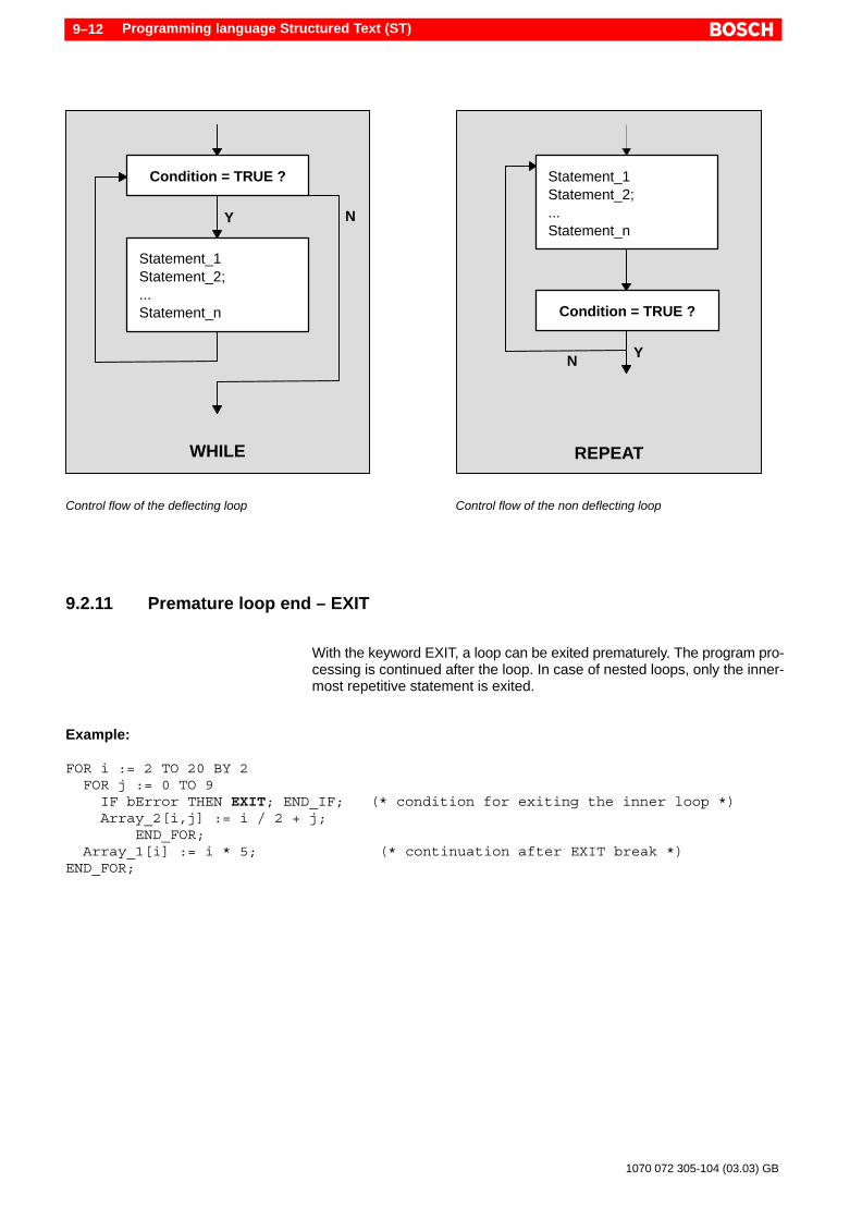
Programming language Structured Text (ST)9–12
1070 072 305-104 (03.03) GB
Condition = TRUE ?
Statement_1Statement_2;...Statement_n
WHILE
Y N
Condition = TRUE ?
Statement_1Statement_2;...Statement_n
REPEAT
YN
Control flow of the deflecting loop Control flow of the non deflecting loop
9.2.11 Premature loop end – EXIT
With the keyword EXIT, a loop can be exited prematurely. The program pro-cessing is continued after the loop. In case of nested loops, only the inner-most repetitive statement is exited.
Example:
FOR i := 2 TO 20 BY 2 FOR j := 0 TO 9 IF bError THEN EXIT; END_IF; (* condition for exiting the inner loop *) Array_2[i,j] := i / 2 + j; END_FOR; Array_1[i] := i * 5; (* continuation after EXIT break *)END_FOR;

Check load and test program 10–1
1070 072 305-104 (03.03) GB
10 Check load and test program
What distinguishes the modules (POU) of the IEC 61131-3 from most of theclassical programming languages is that they cannot be loaded directly. Af-ter the entry of a program, the following processing steps must be followed:
D Compile module = Translate into program codeD Link all modules = Link into an integrated programD Afterwards, the program is loaded in the controller
The processing steps can be carried out independent of each other. In orderto accelerate the loading process, after each program change, WinSPSidentifies which modules are to be compiled and which are not to be compi-led.
Program tracking and data observation in the WinSPS Monitor are useful forcommissioning and error detection, refer to section 10.5.
10.1 Check / compile module
This function allows checking of an individual module and must be executedafter entering all the rows of a POU and after every change.
Since a POU forms a closed unit in itself, the compiler can translate this inde-pendent of other program parts into a program code that can be run (Compi-lation). Thus, all modules can be converted into the program code gradually.
This allows a step by step program development. Partial programs can bedeveloped and tested independently.
In the POU, entire call interface data is known with the declaration inVAR_INPUT, VAR_OUTPUT, VAR_IN_OUT and VAR_EXTERNAL. As a re-sult, all modules can be subsequently linked quickly into an integrated pro-gram.
WinSPS callMenu File " Check / Compile ModuleKeyboard shortcut <Ctrl> + <Alt> + <C>Tool bar
Compiler messagesIn the IEC editor, the lower window area is used for displaying errors aftertesting, refer to section 5.3.
. Only modules, which are compiled error-free, can be loaded in the con-troller.
Check load and test program10–2
1070 072 305-104 (03.03) GB
10.2 Link all modules – Create new project
All modules are linked into an entire program. The “linker” identifies from thecall structure all those modules (POU), which belong to a project. Therefore,POU and file names may not appear more than once in a project.
Example:File name: MODULE.IL POU Name: Module_1File name: MODULE.ST POU Name: Module_2
Though the POU names of both the modules in this example are different,yet the filenames within a project may not be identical; not even when theyare used for different programming languages as shown here.
WinSPS callMenu File " Create new projectKeyboard shortcut <Ctrl> + <Alt> + <G>
Executable program filesBefore executing the linker function, all modules are compiled automatically.Subsequently, executable program files (FC) are generated from the modu-les (POU) in the ASCII format. For the data of a POU, modules are genera-ted. The names of this program and data modules are independent of theproject specifications in the symbol file, refer to section 10.3.
. In case calls of IEC modules out of the classical programming langua-ges are to be realized, the calls must be made before the generation,also refer to section 11.2.
Identification of the main programIn the symbol file, the module for the main program must be entered at theposition for “OM1”. Here, differentiation is made between the pure program-ming as per IEC 61131-3 and the mixed programming with the classical pro-gram parts:
D Pure IEC programming: The file name of the PROGRAM POU is entered by WinSPS automati-cally at the position of the OM1. If this entry is missing, the entry can bemade manually, e.g..
OM1,R IEC_PROG ; Cyclic program processing
D Mixed programming The file name for the organization module OM1 must in any event be ent-ered by hand in the symbol file, e.g.
OM1,R OM1 ; Cyclic program processing

Check load and test program 10–3
1070 072 305-104 (03.03) GB
Linker messagesError messages are mostly attributed to the inconsistencies of the interfa-ces, global and external data or to the crossing of the physical address area.
Error messages are outputted should errors be detected during compilationor linking. Using the button “Go to”, one can jump to the error position withinthe module.
Compiler error during “Create new project”
For a module, an error message appears in the lower editor window. Rowsand character position can however be uniquely identified and indicated bythe linker only in exceptional cases.
Error message of the linker (Create new project)

Check load and test program10–4
1070 072 305-104 (03.03) GB
10.3 Project specifications in the symbol file
With the creation of a project are the ASCII rows of the IEC files convertedinto executable control instructions and set into the program modules. Datamodules are generated, in which all variables are stored. Various necessarysymbols are entered in the symbol file. The following modules are generatedby WinSPS automatically:
D Program files Name.PXO, where the name corresponds to the file nameof the IL or ST file
D Data module IM512.PXD to IM1023.PXD, as well as IM0.PXD
IM0.PXD is generated only in case of pure IEC programming – without clas-sical program parts – for the data of the PROGRAM POU.
. The automatic generation of data modules refers to WinSPS version3.1 and lower. In future versions of the WinSPS, no data modules arereserved and set up.
Moreover, the following symbolic identifiers are given in the symbol file:
D Symbols FC512 to FC1023D Symbols DM512 to DM1023, as well as DM0
The numbering is control dependent and can be adjusted in the symbol filedepending upon the application. Two areas are reserved there for the auto-matically generated symbols, refer to the example given below. The numberstarts with the number after “Start section” and ends with “End section”. Inthe symbol file, the limits can be adjusted by changing these numbers whenneeded. As far as possible, this must take place before the first compilationor linking of the project.
In the data module area, not only symbols but the names for automaticallygenerated data modules IMx.PXD are adjusted. The numbering for DM0(IM0.PXD) cannot be changed.
. WinSPS generates symbol names and the associated files only for freenumbers within the specified area.If a module generated by the user already exists in this area, WinSPSdoes not change the entry and the module, instead, continues with theautomatic generation with the next free number.
Example; *** BEGIN ST program module ***; In this area only the following values are allowed...; Start section = 512; End section = 1023
; *** BEGIN ST data module ***; In this area only the following values are allowed...; Start section = 512; End section = 1023

Check load and test program 10–5
1070 072 305-104 (03.03) GB
Identification of the main programMoreover, in the symbol file the module for the main program must be ent-ered at the position for “OM1”, refer to section 10.2.
10.4 Load program and modules
All modules are loaded in the controller. The loading of partial programs orthe post–loading of individual modules is not possible. Always the completeprogram is loaded.
In case of mixed programming with classical program parts, individual non-IEC modules can also be post–loaded.
Only error free compiled and linked modules are loaded. In case modulesare not compiled and linked free of errors (regenerate project), the compileror linker function fo this module is called up automatically before loading.
WinSPS callMenu Controller " LoadKeyboard shortcu t<Ctrl> + <Alt> + <L>
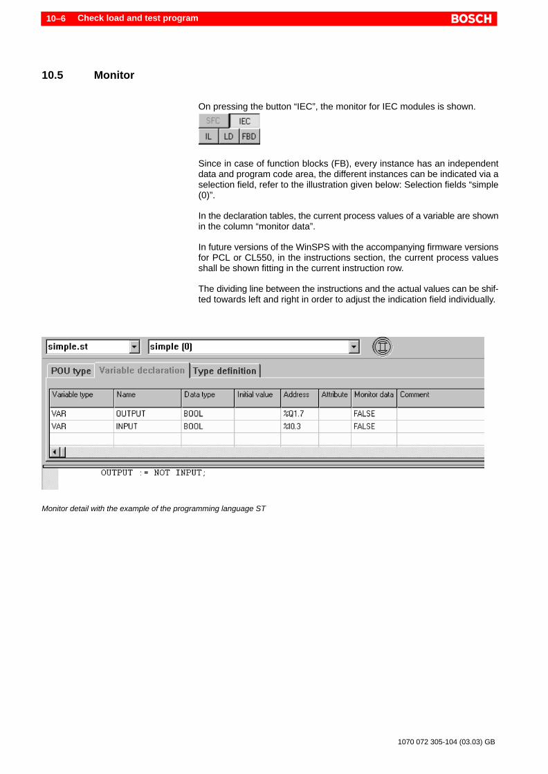
Check load and test program10–6
1070 072 305-104 (03.03) GB
10.5 Monitor
On pressing the button “IEC”, the monitor for IEC modules is shown.
Since in case of function blocks (FB), every instance has an independentdata and program code area, the different instances can be indicated via aselection field, refer to the illustration given below: Selection fields “simple(0)”.
In the declaration tables, the current process values of a variable are shownin the column “monitor data”.
In future versions of the WinSPS with the accompanying firmware versionsfor PCL or CL550, in the instructions section, the current process valuesshall be shown fitting in the current instruction row.
The dividing line between the instructions and the actual values can be shif-ted towards left and right in order to adjust the indication field individually.
Monitor detail with the example of the programming language ST
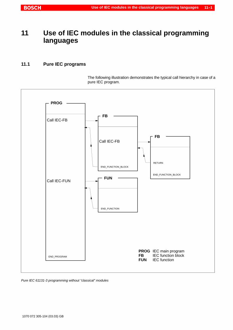
Use of IEC modules in the classical programming languages 11–1
1070 072 305-104 (03.03) GB
11 Use of IEC modules in the classical programminglanguages
11.1 Pure IEC programs
The following illustration demonstrates the typical call hierarchy in case of apure IEC program.
Call IEC-FB
Call IEC-FUN
Call IEC-FB
PROG
FB
FB
FUN
END_FUNCTION
END_FUNCTION_BLOCK
END_FUNCTION_BLOCK
END_PROGRAM
RETURN
PROG IEC main programFB IEC function blockFUN IEC function
Pure IEC 61131-3 programming without “classical” modules

Use of IEC modules in the classical programming languages11–2
1070 072 305-104 (03.03) GB
11.2 Mixed programs
In addition to the “pure” IEC programming with the POU types PROG, FBand FUN, Bosch allows the calling of IEC modules from the “classical” pro-gramming languages Instruction List (Bosch-IL) and Sequential FunctionChart (SFC).
A few conditions and options exist if the classical programming languagesare mixed with the IEC programming:
D IEC modules (POU) may be called up from a classical OM (OrganisationModule) or FB (Functions Block, Program Module).
D Moreover, IEC modules can be called up in a step action in the program-ming language SFC or within the PLC instructions for a step, refer to sec-tion11.3.4.
D Presently, only IEC modules of the type FUNCTION_BLOCK (FB) can becalled up.
D While calling an FB, an instance of the FB is built even in the classicalprogramming environment. The instance building is managed by theuser with the help of a WinSPS wizard, refer to section 11.3.
D IEC modules cannot call up any “classical” modules.D IEC modules can call up other IEC modules (FB and FUN).D In place of the PROGRAM POU, the organization moduleOM1 is used as
the main program.D The module OM1 must be entered by hand in the symbol file, e.g.
OM1,R OM1 ; Cyclic program processing
D Operands from the symbol file can also be used in the IEC modules, or forthe call interface from a classical to an IEC module.
D Type definitions, which were entered in the global type editor (refer to5.5), can also be used in the mixed programs, refer to section 11.4.4.
D In order to allow use of physical addresses (inputs, outputs and markers)in the mixed programming, WinSPS provides a suitable mechanismusing the symbol file, refer to section 11.4.1.
The following illustration demonstrates the possible call hierarchy in a mixedprogram. The example illustrates the call to an IEC function block (FB).

Use of IEC modules in the classical programming languages 11–3
1070 072 305-104 (03.03) GB
Call FC
Call IEC-FB
Call FC
OM1 *
FC *
EM
EM
FC *
EM
Call IEC-FUN
FB
FUN
END_FUNCTION_BLOCK END_FUNCTION
OM1 Main programFC classical FBFB IEC function blockFUN IEC function
* Modules of the classical programming languages have a grey background
Calling up IEC modules from an “classical” programming language.

Use of IEC modules in the classical programming languages11–4
1070 072 305-104 (03.03) GB
11.3 Function block call
Bosch allows the call to IEC POUs of the type FUNCTION_BLOCK (FB)from the classical programming languages Instructions List (Bosch-IL) orwithin the Sequential Function Chart (SFC) in a step action or the PLC in-structions for a step, refer to the example in section 11.3.4.
Entries in the symbol fileIn place of the PROGRAM POU, the organization module OM1 is used asmain program. This module must be entered by hand in the symbol file, e.g.OM1,R OM1 ; Cyclic program processing
All other program modules (FC), which are used in the program, must like-wise be entered by hand in the symbol file. IEC modules (function blocks andfunctions) are basically managed by WinSPS automatically and do not haveto be entered by hand in the symbol file.
Instance callsAs in the case of pure IEC programming , here also instances are called upand not the FB itself . Information concerning the instance of a function blockcan be found in section 6.6.
Multiple working steps following one after another are required for the call:
1. The FB to be called up must be created and compiled free ofany errors.
2. In the symbol file, all operands must be declared, which are tobe used as actual parameters of the FB call interface, also referto section 11.4 and 6.5.3.
3. The write cursor must be positioned in a free row of theBosch-IL module – better in an empty network. At this position,the FB call is inserted.
4. Using the menu function Edit " Call up parameter list,thewizard for inserting a POU call is started. Multiple dialog win-dows appear one after another, refer to section 11.3.1.
With the menu function File " Create new project, all calls are checkedand converted into an executable program (linked).

Use of IEC modules in the classical programming languages 11–5
1070 072 305-104 (03.03) GB
11.3.1 Call parameter list – wizard for FB call
The menu function Edit " Call up parameter list or the key combination<Ctrl> + <P> opens a dialog window for the selection of library and IEC mo-dules.
Select blockAll classical Bosch function blocks with parameter header as well as the IECmodules are listed . The modules available for selection are sorted in the al-phabetical order. The IEC function blocks can be found under the letter “P”for POU. If no FBs are shown, either none exist or are not compiled free ofany errors.
The module call always takes place unconditionally (CM).
Select the desired FB from the list and press “Next”.
First dialog window of the wizard for function block calls
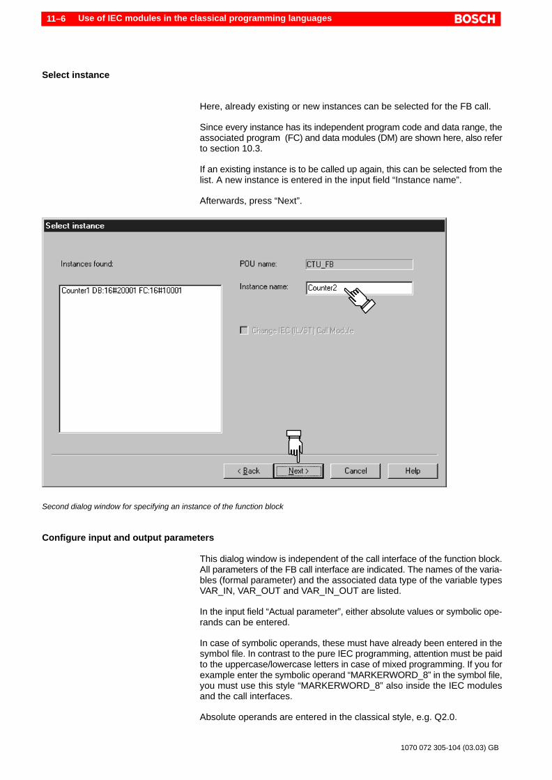
Use of IEC modules in the classical programming languages11–6
1070 072 305-104 (03.03) GB
Select instance
Here, already existing or new instances can be selected for the FB call.
Since every instance has its independent program code and data range, theassociated program (FC) and data modules (DM) are shown here, also referto section 10.3.
If an existing instance is to be called up again, this can be selected from thelist. A new instance is entered in the input field “Instance name”.
Afterwards, press “Next”.
Second dialog window for specifying an instance of the function block
Configure input and output parameters
This dialog window is independent of the call interface of the function block.All parameters of the FB call interface are indicated. The names of the varia-bles (formal parameter) and the associated data type of the variable typesVAR_IN, VAR_OUT and VAR_IN_OUT are listed.
In the input field “Actual parameter”, either absolute values or symbolic ope-rands can be entered.
In case of symbolic operands, these must have already been entered in thesymbol file. In contrast to the pure IEC programming, attention must be paidto the uppercase/lowercase letters in case of mixed programming. If you forexample enter the symbolic operand “MARKERWORD_8” in the symbol file,you must use this style “MARKERWORD_8” also inside the IEC modulesand the call interfaces.
Absolute operands are entered in the classical style, e.g. Q2.0.

Use of IEC modules in the classical programming languages 11–7
1070 072 305-104 (03.03) GB
Entries in the symbol file for example in the illustration below:I2.0,BOOL SET1;I2.1,BOOL SET2;I2.2,BOOL RES;
Last dialog window for the specification of the parameters of the call interface
Afterwards, press “Finish”. With this, a module call is generated by WinSPSautomatically in the Bosch-IL. Moreover, entries are accepted in the symbolfile.
CAUTIONDo not change the automatic entries in the Bosch-IL and the symbolfile!Especially, the comment rows must remain unchanged so that theWinSPS can manage the calls of the IEC modules!
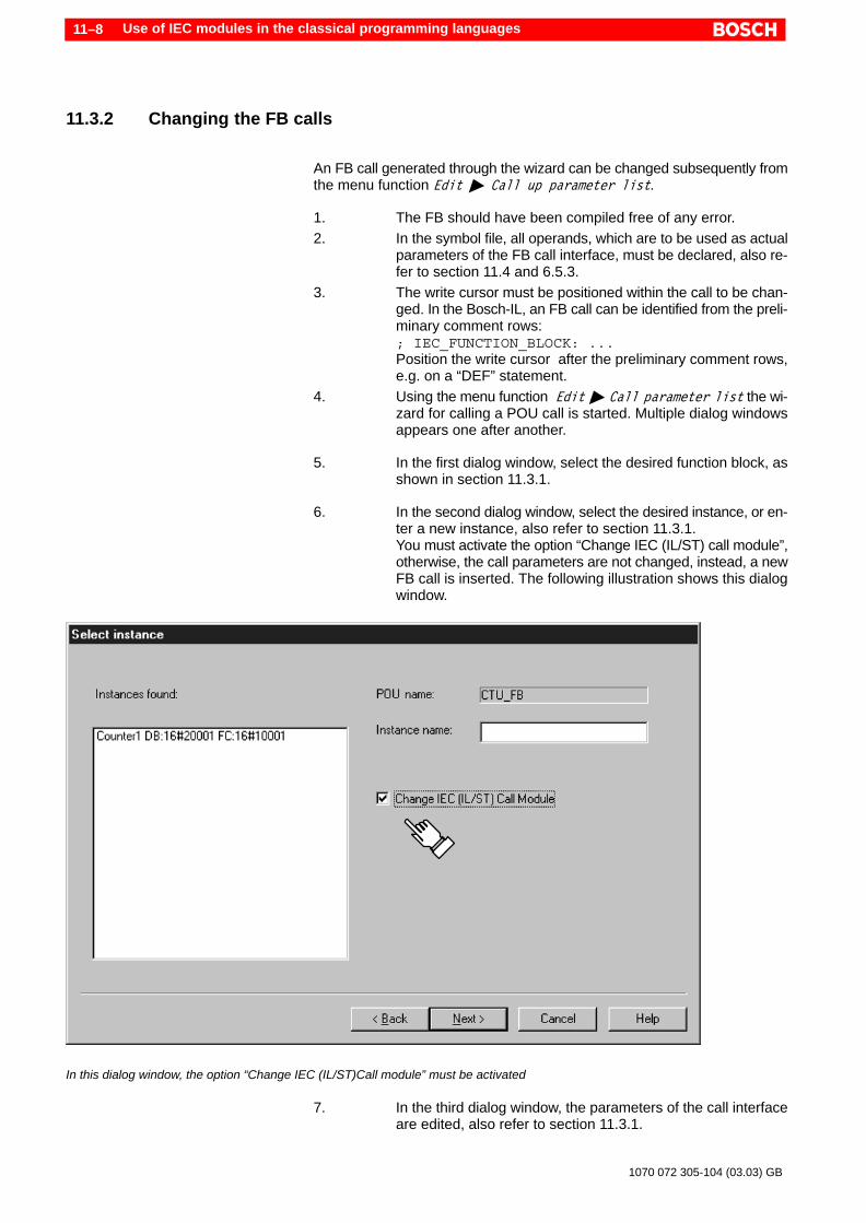
Use of IEC modules in the classical programming languages11–8
1070 072 305-104 (03.03) GB
11.3.2 Changing the FB calls
An FB call generated through the wizard can be changed subsequently fromthe menu function Edit " Call up parameter list.
1. The FB should have been compiled free of any error.2. In the symbol file, all operands, which are to be used as actual
parameters of the FB call interface, must be declared, also re-fer to section 11.4 and 6.5.3.
3. The write cursor must be positioned within the call to be chan-ged. In the Bosch-IL, an FB call can be identified from the preli-minary comment rows:; IEC_FUNCTION_BLOCK: ...Position the write cursor after the preliminary comment rows,e.g. on a “DEF” statement.
4. Using the menu function Edit " Call parameter list the wi-zard for calling a POU call is started. Multiple dialog windowsappears one after another.
5. In the first dialog window, select the desired function block, asshown in section 11.3.1.
6. In the second dialog window, select the desired instance, or en-ter a new instance, also refer to section 11.3.1.You must activate the option “Change IEC (IL/ST) call module”,otherwise, the call parameters are not changed, instead, a newFB call is inserted. The following illustration shows this dialogwindow.
In this dialog window, the option “Change IEC (IL/ST)Call module” must be activated
7. In the third dialog window, the parameters of the call interfaceare edited, also refer to section 11.3.1.
Use of IEC modules in the classical programming languages 11–9
1070 072 305-104 (03.03) GB
With the menu function File " Create new project, all calls are checkedand converted (linked) into an executable program.
11.3.3 Deleting the FB calls
In order to delete an FB call from a Bosch-IL, the automatically generatedentries must be deleted by hand:
FB and instanceWithin the Bosch-IL module, an FB call can be identified from the preliminarycomment rows:
; IEC_FUNCTION_BLOCK: ...
You can find the instance names further below:
; IEC_INSTANCE: ...
Delete FB callIf for the call, you have created a separate network in the Bosch IL, the net-work can thus be simply deleted.
In case, other statements in addition to the FB call exist in the network, deletethe program rows between the comment markings
; IEC_FUNCTION_BLOCK: ...
and
; END_IEC_FUNCTION_BLOCK
(including these rows).
Cleaning upWith the menu function File " Create new project, the symbols, whichhave become redundant, are removed from the symbol file, and with this, theproject is updated to the current status.

Use of IEC modules in the classical programming languages11–10
1070 072 305-104 (03.03) GB
11.3.4 Call in the Sequential Function Chart
The call to a function block (FUNCTION_BLOCK) is possible in two ways in-side the Sequential Function Chart (SFC):
D In a step actionD Within the PLC instructions, in a single step
PLC instructions in a step action
Marking forexistingPLC instructions
PLC instructions in a single step
PLC instructions are entered in the network “User IL”. Position the write cur-sor in a free IL row, in which the FB call can be inserted. The call takes placeas described in section 11.3.
. Kindly take care that the PLC instructions are executed in a step actionor in a single step in each PLC cycle. If the processing should takeplace dependent upon the step, this can be achieved by the jump state-ment “JPCI”, refer to the example.
Example:JPCI End4n5 (* Jump when the step is not active *)
End4n5:
The example shows the PLC instructions of a step function for the step“4N5”. With the instruction “JPCI End4n5”, the PLC instructions are execu-ted only when the step “4N5” is active.The FB call can be inserted e.g. between the instructions “JPCI End4n5”and “End4n5:” .After the label “End4n5:”, instructions can be inserted, which are to be ex-ecuted in every PLC cycle.
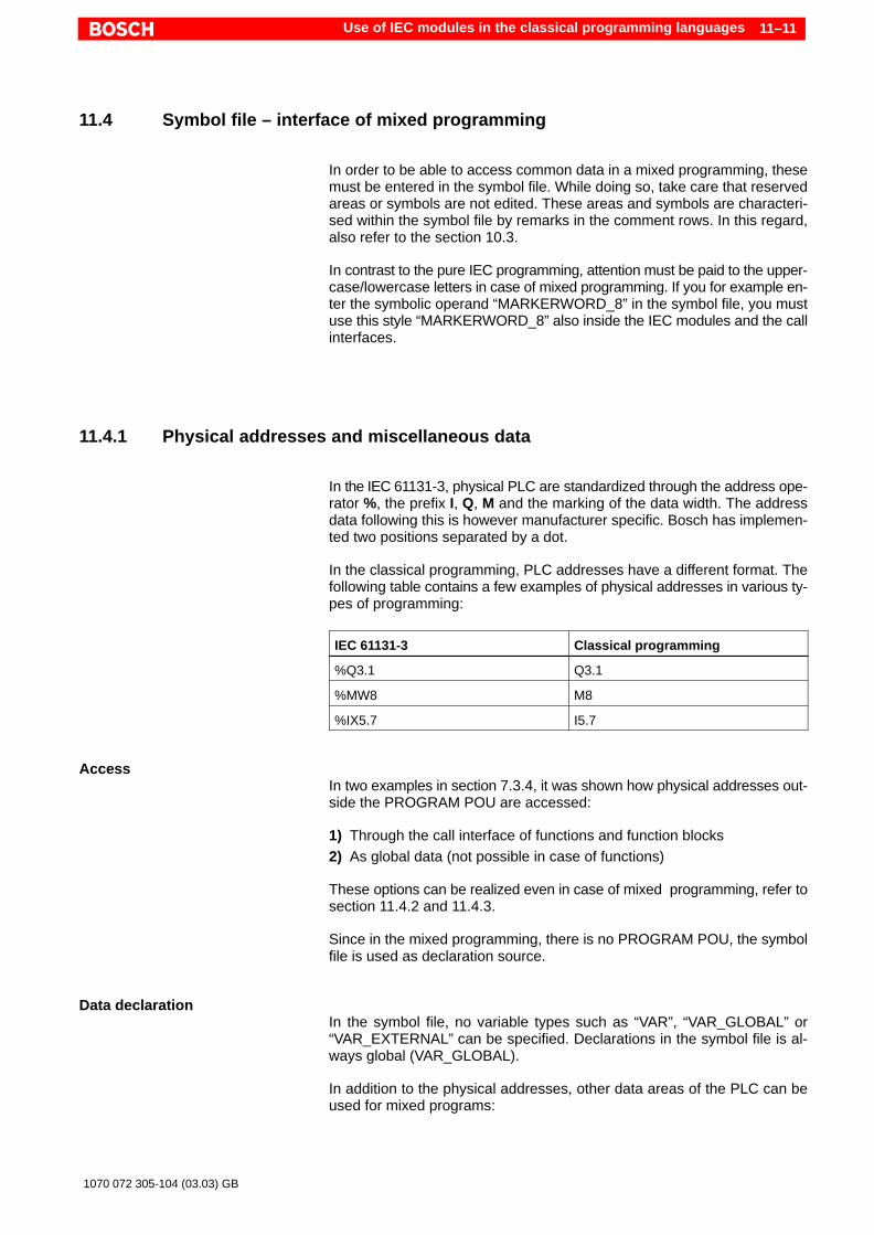
Use of IEC modules in the classical programming languages 11–11
1070 072 305-104 (03.03) GB
11.4 Symbol file – interface of mixed programming
In order to be able to access common data in a mixed programming, thesemust be entered in the symbol file. While doing so, take care that reservedareas or symbols are not edited. These areas and symbols are characteri-sed within the symbol file by remarks in the comment rows. In this regard,also refer to the section 10.3.
In contrast to the pure IEC programming, attention must be paid to the upper-case/lowercase letters in case of mixed programming. If you for example en-ter the symbolic operand “MARKERWORD_8” in the symbol file, you mustuse this style “MARKERWORD_8” also inside the IEC modules and the callinterfaces.
11.4.1 Physical addresses and miscellaneous data
In the IEC 61131-3, physical PLC are standardized through the address ope-rator %, the prefix I, Q, M and the marking of the data width. The addressdata following this is however manufacturer specific. Bosch has implemen-ted two positions separated by a dot.
In the classical programming, PLC addresses have a different format. Thefollowing table contains a few examples of physical addresses in various ty-pes of programming:
IEC 61131-3 Classical programming
%Q3.1 Q3.1
%MW8 M8
%IX5.7 I5.7
AccessIn two examples in section 7.3.4, it was shown how physical addresses out-side the PROGRAM POU are accessed:
1) Through the call interface of functions and function blocks2) As global data (not possible in case of functions)
These options can be realized even in case of mixed programming, refer tosection 11.4.2 and 11.4.3.
Since in the mixed programming, there is no PROGRAM POU, the symbolfile is used as declaration source.
Data declarationIn the symbol file, no variable types such as “VAR”, “VAR_GLOBAL” or“VAR_EXTERNAL” can be specified. Declarations in the symbol file is al-ways global (VAR_GLOBAL).
In addition to the physical addresses, other data areas of the PLC can beused for mixed programs:

Use of IEC modules in the classical programming languages11–12
1070 072 305-104 (03.03) GB
Operand Explanation
I Physical input
Q Physical output
M Marker
SM Special marker
DB Data buffer
DF Data field
FormatDeclaration format of commonly usable operands in the symbol file:
Operand,data type Variable name
. The data type is specified directly after the (absolute) operand – sepa-rated by comma. No space or delimiter may be set in between.
The specification of the data type is optional. In the IEC modules however achecking of the data type is carried out. It is recommended that always thesuitable data be specified so that on project generation (linking), no war-nings are outputted.
The variable name must comply with the rules for the identifiers, refer to sec-tion 7.1.2.
ExamplesQ3.1,BOOL Q3_1MW8,WORD MARKERWORD_8I5.7,BOOL SENSOR_1
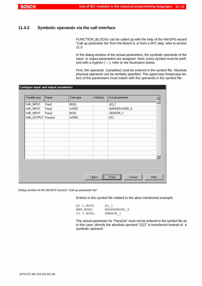
Use of IEC modules in the classical programming languages 11–13
1070 072 305-104 (03.03) GB
11.4.2 Symbolic operands via the call interface
FUNCTION_BLOCKs can be called up with the help of the WinSPS wizard“Call up parameter list” from the Bosch-IL or from a SFC step, refer to section11.3.
In the dialog window of the actual parameters, the symbolic operands of theinput or output parameters are assigned. Here, every symbol must be prefi-xed with a hyphen ( – ), refer to the illustration below.
First, the operands (variables) must be entered in the symbol file. Absolutephysical operands can be similarly specified. The uppercase /lowercase let-ters of the parameters must match with the operands in the symbol file.
Dialog window of the WinSPS function “Call up parameter list”
Entries in the symbol file related to the abov-mentioned example:
Q3.1,BOOL Q3_1MW8,WORD MARKERWORD_8I5.7,BOOL SENSOR_1
The actual parameter for “ParaOut” must not be entered in the symbol file asin this case, directly the absolute operand “Q12” is transferred instead of asymbolic operand.

Use of IEC modules in the classical programming languages11–14
1070 072 305-104 (03.03) GB
11.4.3 Symbolic operands as global variables
There is an option for importing the operands declared in the symbol file asglobal variables in FUNCTION_BLOCKs. In this regard, three things mustbe kept in mind:
D Absolute addresses cannot be accessed from IEC modules. All addres-sed must as a result be available in the symbol file as symbolic operands.
D The data type of the symbolic operands must be specified in the symbolfile. If the data type is left out, a warning is given out in the called module atthe time of linking (create new project).
Model entries in the symbol file:Q3.1,BOOL Q3_1MW8,WORD MRKERWORD_8I5.7,BOOL SENSOR_1
Example for access in an IEC module:FUNCTION_BLOCK xyVAR_EXTERNAL Q3_1 : BOOL; MARKERWORD_8 : WORD SENSOR_1 : BOOL;END_VAR...
In the FB, the global variables with the variable type VAR_EXTERNAL areimported. The uppercase /lowercase letters of the variable names mustmatch with the operands in the symbol file.
11.4.4 Global type definitions
Type definitions, which are entered in the global type editor (refer to section5.5), can also be used in the modules of the classical programming langua-ges in the call interface to the IEC modules.
For this, the name of the derived data types is assigned to an operand andvariable names in the symbol file.
FormatDeclaration format for global type definitions in the symbol file:
Operand,data type Variable name
. The data type is specified directly after the (absolute) operand – sepa-rated by comma. No space or delimiter may be set in between, refer tothe example below.
The variable name must comply with the rules for the identifiers, refer to sec-tion 7.1.2.

Use of IEC modules in the classical programming languages 11–15
1070 072 305-104 (03.03) GB
ExampleThe following illustration shows an extract from the type editor with variousderived data types (the elements of the data structure “Structure” are visi-ble).
Global derived data types in the type editor
These data types are declared in the symbol file for the mixed programmingenvironment:
M20,GlobalType INTEGER_125DF0,Structure STRUCTURENAMEDB4,Enumerate COLORS
Working out the data sizeTo start with, with the declaration of a derived data type in the symbol file, an“initial address” is created. All subsequent elements of the data type occupythe memory addresses following this address. Thus for example, a datastructure occupies a continuous memory area depending upon the numberand data size of the structure elements.
BOOL types occupy a complete Byte in the memory.
Moreover, attention must be paid to the maintenance of “base byte addres-ses”. Information concerning this can be found in the software manual of therespective controller.
DANGERWith the declaration of a derived data type in the symbol file, only an“initial address” is created! The subsequent addresses must be wor-ked out from the data size of the derived data types and the displace-ments due to the base byte addresses. Subsequent addresses maynot be used for other access!If subsequent addresses are used repeatedly, data area in the PLCcould get overwritten by mistake!

Use of IEC modules in the classical programming languages11–16
1070 072 305-104 (03.03) GB
Access to global type definitionsIn the classical programming language (Bosch-IL), variable declared in thesymbol file can be used to access the derived data type. However, neitherelements of structures nor the names (text constants) of enumerations canbe accessed.
The declaration in the symbol file should rather allow transfer of a pointer to amemory address in an IEC module. For the transfer of pointer variables, thevariable type “VAR_IN_OUT” in the function blocks is particularly suitable.
Similarly, the access via the variable type “VAR_EXTERNAL” is possible wit-hin a function block.
Example for access viacall interface
The following illustration shows a typical application example for the transferof global data types via the call interface. Using the menu function “Call upparameter list”, an FB call is generated inside the classical module, also referto section 11.3. In the dialog window of the actual parameters, the symbolicoperands of the input or output parameters are assigned. In this example,pointer variables (VAR_IN_OUT) are implemented as parameters:
Dialog window of the WinSPS function “Call up parameter list”
It is important during parameter setting that the derived data types inside theFB declaration match the definition in the type editor, refer to the illustrationabove: Column data type. The uppercase /lowercase letters of the variablenames must match with the entries in the symbol file.

Use of IEC modules in the classical programming languages 11–17
1070 072 305-104 (03.03) GB
Example for access viaVAR_EXTERNAL
The access as global variable is allowed in the function block using the varia-ble type “VAR_EXTERNAL”:
VAR_EXTERNAL INTEGER_125 : GlobalType; STRUCTURENAME : Structure; COLORS : EnumerateEND_VAR
Even here, make sure that the derived data types inside the FB declarationmatch the definition in the type editor. The uppercase/lowercase letters ofthe variable names must match with the entries in the symbol file.
11.5 Differences in case of mixed programming
In case of mixed programming, keep in mind that a few differences exist bet-ween the classical programming and the programming as per IEC 61131-3.The following table shows a comparison of important elements:
IEC 61131-3 Classical programming
Physical addresses Physical addressed are assigned a prefixand data format. Example:%IX3.7
Physical addresses have another format. Ex-ample:I3.7In case of mixed programming, the classicalformat is used throughout.
Strings (strings) The string terminator \0 is automatically ap-pended.
\0 must be appended manually if the string isto be processed free of any error in the IECenvironment.
Arrays and structures The maximum size of arrays and structuresis equal to the data module length minusheader data. Example: Array1 : ARRAY[1.. 502] OF BYTE.502 bytes are allowed, otherwise, an errormessage is given out at the time of compila-tion.
No restriction.
Identifiers Uppercase and lowercase letters do not playany role.
In case of mixed programming, attentionmust be paid to the uppercase / lowercaseletters. If for example the symbolic ope-rand“MARKERWORD_8” is entered in thesymbol file, you must use this style “MAR-KERWORD_8” also inside the IEC modulesand the call interfaces.

Use of IEC modules in the classical programming languages11–18
1070 072 305-104 (03.03) GB
Notes:
Standardized functionality 12–1
1070 072 305-104 (03.03) GB
12 Standardized functionality
In addition to the program and data structure, the IEC 61131-3 also standar-dizes important PLC functionalities. These are predefined in the norm asstandard functions or function blocks. During implementation, all manufac-turers of programming system or module libraries must follow these direc-tions.
12.1 Standard functions
The standard functions are divided in various groups:
D Functions for data conversionD Numeric functionsD Arithmetic functions
(in case of Bosch only through symbolic style, refer to 12.1.5)D Shift functionsD Boolean functionsD Functions for selection and comparison
(Option not currently supported by WinSPS)D Functions for strings (string functions)D Special functions –data type – timeD Special functions – data types – enumeration
(not currently supported by WinSPS)
The following sections include instructions for parameterization and detailedexplanations concerning the standard functions.
. Pay attention to the instructions concerning the norm conformity insection 13.The supported standard functions are listed there.
12.1.1 Generic data types and “overloaded” functions
In many standard functions, the characteristics of generic data types areused, refer to 7.2.3 and the illustration below. As a result of this, input varia-bles of a function can not only be applied for one but multiple data types. Withthis characteristic, they are termed as overload or overloadable functions.
In the following explanation of the standard functions, it is specified thatwhich functions are overloadable and which are not overloadable.
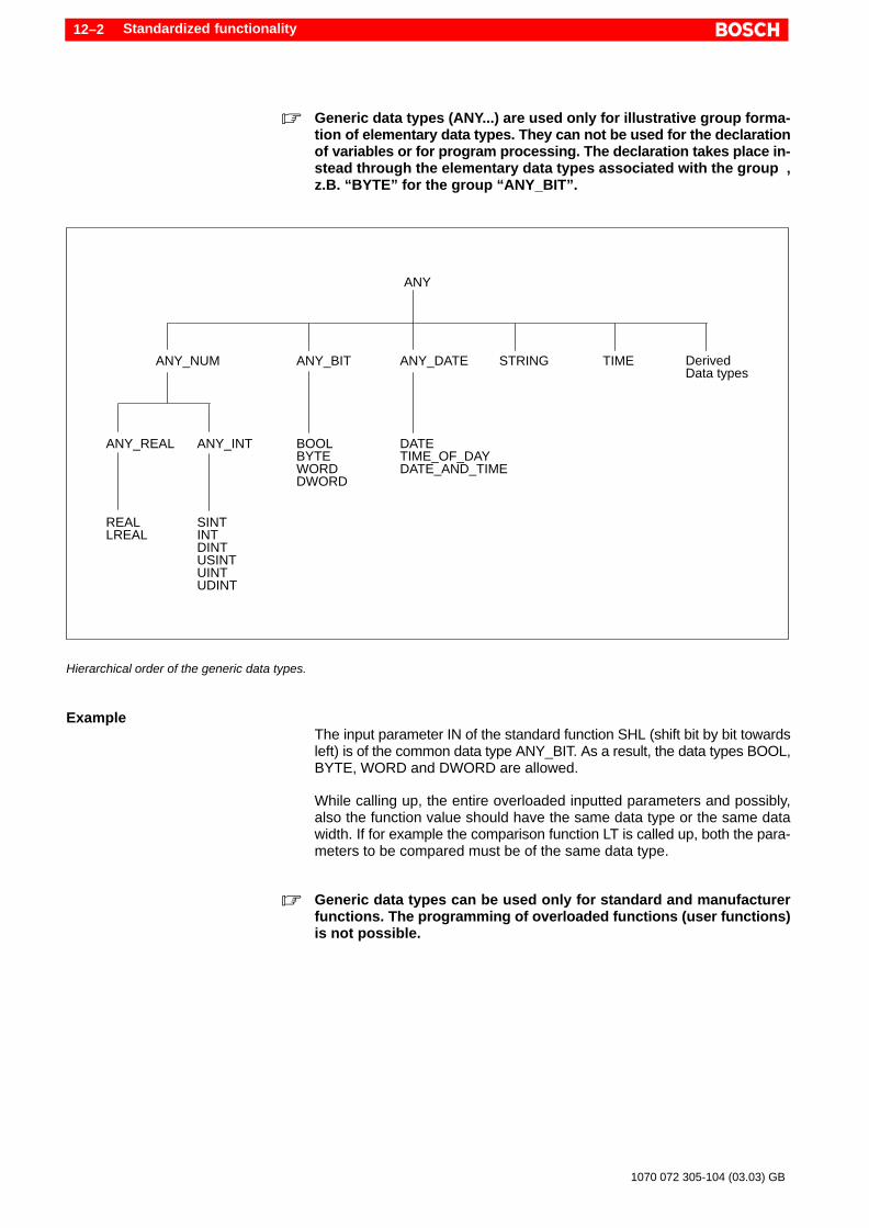
Standardized functionality12–2
1070 072 305-104 (03.03) GB
. Generic data types (ANY...) are used only for illustrative group forma-tion of elementary data types. They can not be used for the declarationof variables or for program processing. The declaration takes place in-stead through the elementary data types associated with the group ,z.B. “BYTE” for the group “ANY_BIT”.
ANY
ANY_NUM ANY_BIT ANY_DATE STRING TIME DerivedData types
ANY_REAL ANY_INT BOOL DATE
SINT
TIME_OF_DAYDATE_AND_TIME
BYTEWORDDWORD
DINTUSINTUINTUDINT
INTREALLREAL
Hierarchical order of the generic data types.
ExampleThe input parameter IN of the standard function SHL (shift bit by bit towardsleft) is of the common data type ANY_BIT. As a result, the data types BOOL,BYTE, WORD and DWORD are allowed.
While calling up, the entire overloaded inputted parameters and possibly,also the function value should have the same data type or the same datawidth. If for example the comparison function LT is called up, both the para-meters to be compared must be of the same data type.
. Generic data types can be used only for standard and manufacturerfunctions. The programming of overloaded functions (user functions)is not possible.
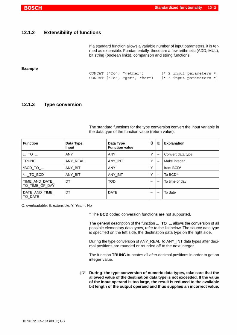
Standardized functionality 12–3
1070 072 305-104 (03.03) GB
12.1.2 Extensibility of functions
If a standard function allows a variable number of input parameters, it is ter-med as extensible. Fundamentally, these are a few arithmetic (ADD, MUL),bit string (boolean links), comparison and string functions.
ExampleCONCAT (”To”, “gether”) (* 2 input parameters *)CONCAT (”To”, “get”, “her”) (* 3 input parameters *)
12.1.3 Type conversion
The standard functions for the type conversion convert the input variable inthe data type of the function value (return value).
Function Data TypeInput
Data TypeFunction value
Ü E Explanation
..._TO_... ANY ANY Y – Convert data type
TRUNC ANY_REAL ANY_INT Y – Make integer
*BCD_TO_... ANY_BIT ANY Y – from BCD*
*..._TO_BCD ANY_BIT ANY_BIT Y – To BCD*
TIME_AND_DATE_TO_TIME_OF_DAY
DT TOD – – To time of day
DATE_AND_TIME_TO_DATE
DT DATE – – To date
O: overloadable, E: extensible, Y: Yes, –: No
* The BCD coded conversion functions are not supported.
The general description of the function ..._TO_... allows the conversion of allpossible elementary data types, refer to the list below. The source data typeis specified on the left side, the destination data type on the right side.
During the type conversion of ANY_REAL to ANY_INT data types after deci-mal positions are rounded or rounded off to the next integer.
The function TRUNC truncates all after decimal positions in order to get aninteger value.
. During the type conversion of numeric data types, take care that theallowed value of the destination data type is not exceeded. If the valueof the input operand is too large, the result is reduced to the availablebit length of the output operand and thus supplies an incorrect value.

Standardized functionality12–4
1070 072 305-104 (03.03) GB
Examples (programming language ST):Var := INT_TO_UDINT (–200); (* Var := 200 *)Var := INT_TO_SINT (–200); (* does not create any
useful value *)Var := REAL_TO_DINT (–825.66);(* VAR := –826 *)Var := TRUNC (–825.66); (* VAR := –825 *)Var := BYTE_TO_UINT (16#96); (* Var := 150 *)Var := INT_TO_BOOL (100); (* Var := TRUE *)Var := INT_TO_BOOL (0); (* Var := FALSE *)
DANGERThe functions for the type conversion ..._TO_STRING andSTRING_TO_... are under preparation. However, no error message isgenerated during compilation.A run-time error would occur in the controller and the controllerwould STOP!
The following list shows all the possible type conversion functions “...TO...”:
BOOL_TO_BYTE BOOL_TO_DINT BOOL_TO_DWORD BOOL_TO_INT BOOL_TO_SINTBOOL_TO_TIME BOOL_TO_UDINT BOOL_TO_UINT BOOL_TO_USINT BOOL_TO_WORD
BYTE_TO_BOOL BYTE_TO_DINT BYTE_TO_DWORD BYTE_TO_INT BYTE_TO_SINTBYTE_TO_TIME BYTE_TO_UDINT BYTE_TO_UINT BYTE_TO_USINT BYTE_TO_WORD
DINT_TO_BOOL DINT_TO_BYTE DINT_TO_DWORD DINT_TO_INT DINT_TO_SINTDINT_TO_TIME DINT_TO_UDINT DINT_TO_UINT DINT_TO_USINT DINT_TO_WORD
DWORD_TO_BOOL DWORD_TO_BYTE DWORD_TO_DINT DWORD_TO_INT DWORD_TO_SINTDWORD_TO_TIME DWORD_TO_UDINT DWORD_TO_UINT DWORD_TO_USINT DWORD_TO_WORD
INT_TO_BOOL INT_TO_BYTE INT_TO_DINT INT_TO_DWORD INT_TO_SINTINT_TO_TIME INT_TO_UDINT INT_TO_UINT INT_TO_USINT INT_TO_WORD
SINT_TO_BOOL SINT_TO_BYTE SINT_TO_DINT SINT_TO_DWORD SINT_TO_INTSINT_TO_TIME SINT_TO_UDINT SINT_TO_UINT SINT_TO_USINT SINT_TO_WORD
TIME_TO_BOOL TIME_TO_BYTE TIME_TO_DINT TIME_TO_DWORD TIME_TO_INTTIME_TO_SINT TIME_TO_UDINT TIME_TO_UINT TIME_TO_USINT TIME_TO_WORD
UDINT_TO_BOOL UDINT_TO_BYTE UDINT_TO_DINT UDINT_TO_DWORD UDINT_TO_INTUDINT_TO_SINT UDINT_TO_TIME UDINT_TO_UINT UDINT_TO_USINT UDINT_TO_WORD
UINT_TO_BOOL UINT_TO_BYTE UINT_TO_DINT UINT_TO_DWORD UINT_TO_INTUINT_TO_SINT UINT_TO_TIME UINT_TO_UDINT UINT_TO_USINT UINT_TO_WORD
USINT_TO_BOOL USINT_TO_BYTE USINT_TO_DINT USINT_TO_DWORD USINT_TO_INTUSINT_TO_SINT USINT_TO_TIME USINT_TO_UDINT USINT_TO_UINT USINT_TO_WORD
WORD_TO_BOOL WORD_TO_BYTE WORD_TO_DINT WORD_TO_DWORD WORD_TO_INTWORD_TO_SINT WORD_TO_TIME WORD_TO_UDINT WORD_TO_UINT WORD_TO_USINT

Standardized functionality 12–5
1070 072 305-104 (03.03) GB
12.1.4 Numeric functions
The data type of the input parameter must match with the data type of thefunction value.
Function Data TypeInput
Data TypeFunction value
Ü E Explanation
ABS ANY_NUM ANY_NUM Y – Absolute value
SQRT ANY_REAL ANY_REAL Y – Square root
LN ANY_REAL ANY_REAL Y – Natural algorithm
LOG ANY_REAL ANY_REAL Y – Algorithm base 10
EXP ANY_REAL ANY_REAL Y – Exponentiation
SIN ANY_REAL ANY_REAL Y – Sine function
COS ANY_REAL ANY_REAL Y – Cosine function
TAN ANY_REAL ANY_REAL Y – Tangent function
ASIN ANY_REAL ANY_REAL Y – Inverse sine function
ACOS ANY_REAL ANY_REAL Y – Inverse cosine function
ATAN ANY_REAL ANY_REAL Y – Inverse tangent function
O: overloadable, E: extensible, Y: Yes, –: No
Example (IL):LD AlphaCOSST cosAlpha (* Cosine *)
Eample (ST):cosAlpha := COS (Alpha); (* Cosine *)
12.1.5 Arithmetic functions
. In the programming language ST, while processing the data types“ANY_NUM”, only the symbolic style of the arithmetic standard func-tions can be entered.
Example:Var1 := Var2 + Var3 + Var4; (* error free *)Var1 := ADD (Var2, Var3, Var4); (* is reported as
error *)
The modfier for the symbolic style is specified in the table in column “M”.

Standardized functionality12–6
1070 072 305-104 (03.03) GB
Function M Data TypeInput
Data TypeFunction value
Ü E Explanation
ADD + ANY_NUMANY_NUM
ANY_NUM Y Y Addition
ADD + TIMETIME
TIME Y – Time addition
ADD + TODTIME
TOD Y – Time addition
ADD + DTTIME
DT Y – Time addition
MUL * ANY_NUMANY_NUM
ANY_NUM Y Y Multiplication
MUL * TIMEANY_NUM
TIME Y – Time multiplication
SUB – ANY_NUMANY_NUM
ANY_NUM Y – Subtraction
SUB – TIMETIME
TIME Y – Time subtraction
SUB – DATEDATE
TIME Y – Time subtraction
SUB – TODTIME
TOD Y – Time subtraction
SUB – TODTOD
TIME Y – Time subtraction
SUB – DTTIME
DT Y – Time subtraction
SUB – DTDT
TIME Y – Time subtraction
DIV / ANY_NUMANY_NUM
ANY_NUM Y – Division
DIV / TIMEANY_NUM
TIME Y – Time division
MOD ANY_NUMANY_NUM
ANY_NUM Y – Modulo, residue bilding
EXPT ANY_NUMANY_NUM
ANY_NUM Y – Exponent
MOVE ANY_NUMANY_NUM
ANY_NUM Y – Assignment
S: Symbolic style, O: overloadable, E: extensible, Y: Yes, –: No
If the division of an integer does not result in an integer, the after decimalpositions are truncated.
. The division by zero is not allowed!
Example (ST):todMESZ:= ADD (todMEZ, T#1h); (* Addition with the
type time of day *)

Standardized functionality 12–7
1070 072 305-104 (03.03) GB
12.1.6 Shift functions
The data type of the first input parameter must match with the data type of thefunction value.
The second input parameter “N” must contain an integer value. The parame-ter contains the number of the positions to be shifted or rotated.
Function Data TypeInput
Data TypeFunction value
O E Explanation
SHL ANY_BITN
ANY_BIT Y – Shifting towards left(fill with zeros from left)
SHR ANY_BITN
ANY_BIT Y – Shifting towards right(fill with zeros from left)
ROR ANY_BITN
ANY_BIT Y – Rotate towards right(ring shape)
ROL ANY_BITN
ANY_BIT Y – Rotate towards left(ring shape)
O: overloadable, E: extensible, Y: Yes, –: No
Example (ST):%QB8 := SHR (2#01101100, 4); (* Shift 4 positions
towards right *)(* %QB := 2#00000110 *)
Rot1 := ROL (2#11000011, 2); (* Rotate 2 positions towards left *)(* Rot1 := 2#00001111 *)

Standardized functionality12–8
1070 072 305-104 (03.03) GB
12.1.7 Boolean functions – logical links
The data type of the input parameter must match with the data type of thefunction value.
The symbol for the symbolic style is specified in the table in the second co-lumn.
Function S Data TypeInput
Data TypeFunction value
O E Explanation
AND & ANY_BITANY_BIT
ANY_BIT Y Y Logical AND
OR ANY_BITANY_BIT
ANY_BIT Y Y Logical OR
XOR ANY_BITANY_BIT
ANY_BIT Y Y Logical exclusive OR
NOT ANY_BIT ANY_BIT Y – Logical negation
O: overloadable, E: extensible, Y: Yes, –: No
. In the programming language ST, only the symbolic style of the arith-metic standard functions can be entered.
Examples (IL):LDN BAND AST C
LD 2#10100110 (* Bit pattern *)& 2#11110000ST %QB0
Example (ST):C := A AND NOT B;
12.1.8 Selection
Functions for selection are presently not supported.

Standardized functionality 12–9
1070 072 305-104 (03.03) GB
12.1.9 Comparison
The data type ENUM stands for the “derived data type” enumeration, refer to7.2.2.
Function Data TypeInput
Data TypeFunction value
O E Explanation
GT ANYANY
BOOL Y Y Greater than
GE ANYANY
BOOL Y Y Greater than or equal
EQ ANYANY
BOOL Y Y Equal
EQ ENUMENUM
BOOL – – Equal
LT ANYANY
BOOL Y Y Less than
LE ANYANY
BOOL Y Y Less than or equal
NE ANYANY
BOOL Y – Unequal
NE ENUMENUM
BOOL – – Unequal
O: overloadable, E: extensible, Y: Yes, –: No
Example (IL):M1: LD iOperand1
ADD iOperand2ST iResult (* calculation result *)EQ 100 (* comparison CR = 100 ?... *)JMPC M2 (* ...then jump to M2 *)
Example (ST):bLT := LT (Var_1, Var_2); (* Comparison, whether Var_1 is less than Var_2 *)
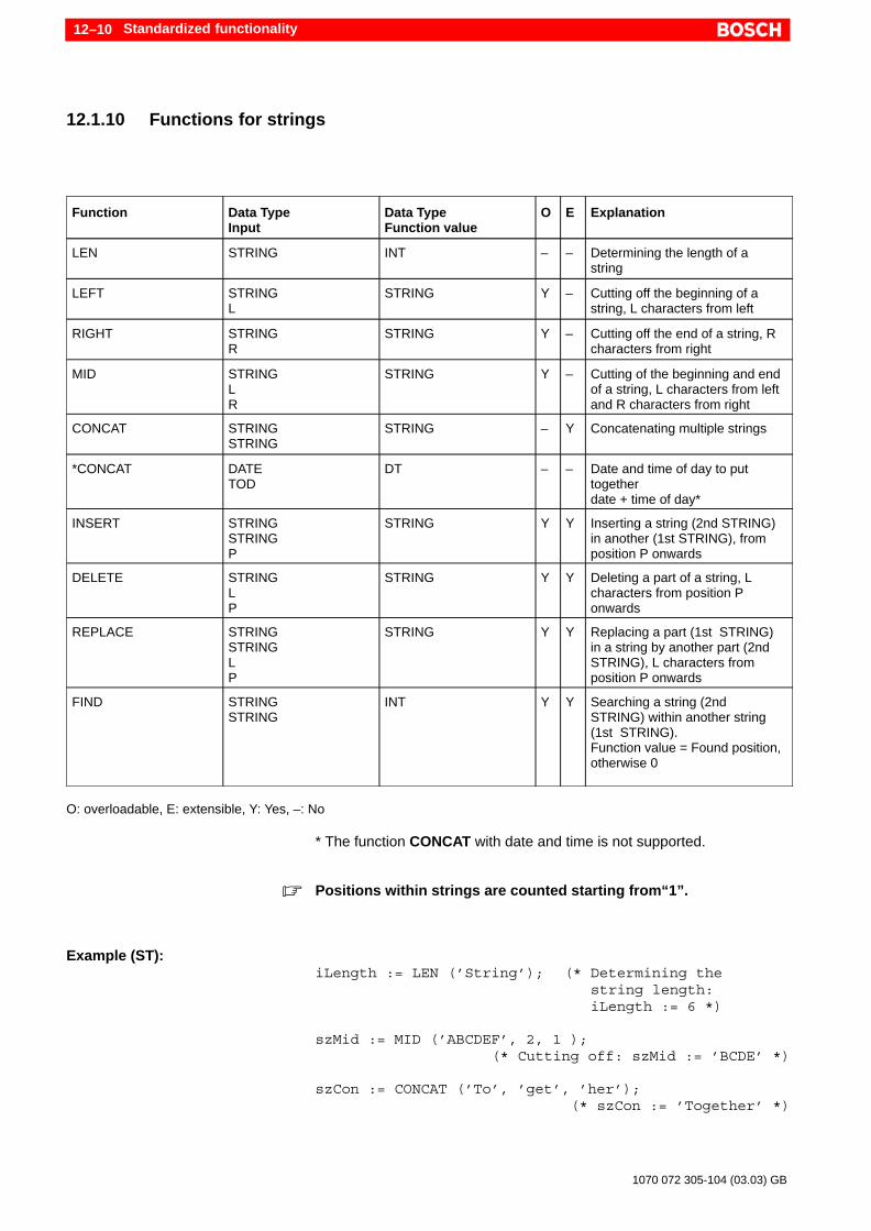
Standardized functionality12–10
1070 072 305-104 (03.03) GB
12.1.10 Functions for strings
Function Data TypeInput
Data TypeFunction value
O E Explanation
LEN STRING INT – – Determining the length of a string
LEFT STRINGL
STRING Y – Cutting off the beginning of astring, L characters from left
RIGHT STRINGR
STRING Y – Cutting off the end of a string, Rcharacters from right
MID STRINGLR
STRING Y – Cutting of the beginning and endof a string, L characters from leftand R characters from right
CONCAT STRINGSTRING
STRING – Y Concatenating multiple strings
*CONCAT DATETOD
DT – – Date and time of day to puttogether date + time of day*
INSERT STRINGSTRINGP
STRING Y Y Inserting a string (2nd STRING)in another (1st STRING), fromposition P onwards
DELETE STRINGLP
STRING Y Y Deleting a part of a string, Lcharacters from position Ponwards
REPLACE STRINGSTRINGLP
STRING Y Y Replacing a part (1st STRING)in a string by another part (2ndSTRING), L characters fromposition P onwards
FIND STRINGSTRING
INT Y Y Searching a string (2ndSTRING) within another string(1st STRING).Function value = Found position,otherwise 0
O: overloadable, E: extensible, Y: Yes, –: No
* The function CONCAT with date and time is not supported.
. Positions within strings are counted starting from“1”.
Example (ST):iLength := LEN (’String’); (* Determining the
string length: iLength := 6 *)
szMid := MID (’ABCDEF’, 2, 1 ); (* Cutting off: szMid := ’BCDE’ *)
szCon := CONCAT (’To’, ’get’, ’her’); (* szCon := ’Together’ *)

Standardized functionality 12–11
1070 072 305-104 (03.03) GB
szNew := INSERT (’ABCDEF’, ’12345’, 3, 2 ); (* Inserting: szNew := ’A123BCDEF’ *)
iPos := FIND (’ABCDEF’, ’DE’ );(* Search: iPos := 4 *)
DANGERIf the size of the string is increased by a function, the related stringvariable must be declared large enough, for example, see below.It can otherwise have the effect that the address range is crossed,which can lead to uncontrolled behavior!
Erroneous example:VAR szVar : STRING (13);END_VAR
szVar := CONCAT (’more ’, ’characters’);
The string variable “szVar” can take 13 characters. In the function call “CON-CAT” however it must be able to accept at least 14 characters. It has the ef-fect that the address range is exceeded.

Standardized functionality12–12
1070 072 305-104 (03.03) GB
12.2 Standard function block
The IEC 61131-3 defines the following standard function blocks which canbe divided in groups:
Name Inputs Outputs Explanation
Bistable elementsSRRS
Set1*,ReSet*Set*,ReSet1*
Q1Q1
Setting on priorityResetting on priority
EdgesR_TRIGF_TRIG
CLKCLK
Detection of rising edgeDetection of falling edge
CounterCTUCTDCTUD
CU,ReSet*,PVCD,Load*,PVCU,CD,R*,Load*,PV
Q,CVQ,CVQU,QD,CV
Forward counterBackward counterforward/backward counter
TimeTPTONTOFRTC
IN,PTIN,PTIN,PTEN,PDT
Q,ETQ,ETQ,ETQ,CDT
Pulse generatorSwitch on delaySwitch off delayReal–time clock
* Refer to instructions
. The key words “R”, “S” und “LD” of the input parameters are used inthe programming language instructions list (IL) with another meaning.Due to this conflict, there are difficulties during translation by a compi-ler. This problem was taken up in the working group for further deve-lopment of the IEC 61131-3. In a revised version of the standard, theparameter names should be changed to “Set”, “ReSet” und “Load”.Bosch already uses this modified form.
. All variables are basically handled as with RETAIN attribute. Excep-tions are the standard FBs. These are basically non-remanent i.e. theyare re-initialized after every STOP/RUN switchover.

Standardized functionality 12–13
1070 072 305-104 (03.03) GB
Description of all input and output parameters:
Parameter Explanation Data Type
CD Input count downwards (Count Down) R_EDGE
CDT Current date and time(Current Date and Time)
DT
CLK Cycle input (CLocK) BOOL
CU Input count upwards (Count UP) R_EDGE
CV Current Value INT
ET Current time (End Time) TIME
IN Time input (INput) BOOL
LOAD (LD) Load counter value (LoaD) INT
PDT Date/time (Preset Date and Time) DT
PT Time (Preset Time) TIME
PV Counter value INT
Q Output BOOL
QD Output downwards (Down) BOOL
QU Output upwards (Up) BOOL
RESET (R) Reset input (Reset) BOOL
R1 R on priority BOOL
SET (S) Set input (Set) BOOL
S1 S on priority BOOL
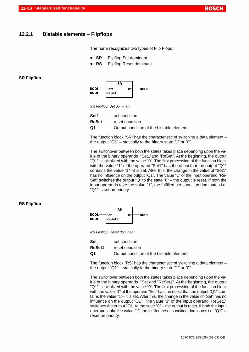
Standardized functionality12–14
1070 072 305-104 (03.03) GB
12.2.1 Bistable elements – Flipflops
The norm recognizes two types of Flip Flops :
D SR Flipflop Set dominantD RS Flipflop Reset dominant
SR Flipflop
SR Flipflop: Set dominant
Set1 set conditionReSet reset conditionQ1 Output condition of the bistable element
The function block ”SR” has the characteristic of switching a data element –the output ”Q1” – statically to the binary state ”1” or ”0”.
The switchover between both the states takes place depending upon the va-lue of the binary operands ”Set1”and ”ReSet”. At the beginning, the output”Q1” is initialized with the value ”0”. The first processing of the function blockwith the value ”1” of the operand ”Set1” has the effect that the output ”Q1”contains the value ”1”– it is set. After this, the change in the value of ”Set1”has no influence on the output ”Q1”. The value ”1” of the input operand ”Re-Set” switches the output ”Q” to the state ”0” – the output is reset. If both theinput operands take the value ”1”, the fulfilled set condition dominates i.e.”Q1” is set on priority.
RS Flipflop
RS Flipflop: Reset dominant
Set set conditionReSet1 reset conditionQ1 Output condition of the bistable element
The function block ”RS” has the characteristic of switching a data element –the output ”Q1” – statically to the binary state ”1” or ”0”.
The switchover between both the states takes place depending upon the va-lue of the binary operands ”Set”and ”ReSet1”. At the beginning, the output”Q1” is initialized with the value ”0”. The first processing of the function blockwith the value ”1” of the operand ”Set” has the effect that the output ”Q1” con-tains the value ”1”– it is set. After this, the change in the value of ”Set” has noinfluence on the output ”Q1”. The value ”1” of the input operand ”ReSet1”switches the output ”Q1” to the state ”0” – the output is reset. If both the inputoperands take the value ”1”, the fulfilled reset condition dominates i.e. ”Q1” isreset on priority.

Standardized functionality 12–15
1070 072 305-104 (03.03) GB
12.2.2 Edge detection
The norm recognizes two different modules for edge detection:
D R_TRIG rising edgeD F_TRIG falling edge
Rising edge R_TRIG
R_TRIG: Rising edge
CLK Input operand, whose rising edge is detectedQ Output operand reports the rising edge of ”CLK”
The function block ”R_TRIG” evaluates the condition of the input operand”CLK”. The condition change from ”0” in a processing cycle to ”1” in the nextprocessing cycle is detected and is indicated through the output ”Q” with thebinary value ”1”. The state ”1” exists at the output only in the processing cy-cle, in which the condition change of ”CLK” is detected and a rising edge isreported.
Falling edge F_TRIG
F_TRIG: Falling edge
CLK Input operand, whose falling edge is detectedQ Output operand reports the falling edge of ”CLK”
The function block ”F_TRIG” evaluates the condition of the input operand”CLK”. The condition change from ”1” in a processing cycle to ”0” in the nextprocessing cycle is detected and is indicated through the output ”Q” with thebinary value ”1”. The state ”1” exists at the output only in the processing cy-cle, in which the condition change of ”CLK” is detected and a falling edge isreported.

Standardized functionality12–16
1070 072 305-104 (03.03) GB
12.2.3 Counter
Counters can follow in different directions. The norm makes three countersavailable:
D CTU Upward counterD CTD Downward counterD CTUD Upward / downward counter
. The inputs of the counter modules are edge triggered (R_EDGE) i.e. arising edge must exist so that the counter value changes.
. Counters must be initialized with count limit or an initial value (PV),otherwise, they do not run!
Upward counter CTU
CTU: Upward counter
CU Count pulse, rising edgeReSet reset conditionPV count limitQ Message: Counter value greater than equal to PVCV Counter value
The function block ”CTU” is used for upward counting of pulses which aresupplied by the input operand ”CU”. During the initialization, the counter getsthe value ”0”. Every rising edge at the input ”CU” increments the counter, i.e.increases its value by one. The counter value can be erased with the value”1” of the operand”ReSet”. The output operand ”CV” supplies the current co-unter value. If the counter value lies below the limit ”PV”, the output operand”Q” takes the binary value ”0”. The reaching or exceeding the limit sets theoutput ”Q” to ”1”.
Downward counter CTD
CTD Downward counter
CD Count pulse, rising edgeLoad set conditionPV initial valueQ Message: Counter value smaller than equal to zeroCV Counter value

Standardized functionality 12–17
1070 072 305-104 (03.03) GB
The function block ”CTD” is used for downward counting of pulses which aresupplied by the input operand ”CD”. During the initialization, the counter getsthe value ”0”. With the value ”1” of the operand ”Load”, the value specified bythe operand ”PV” is accepted as the initial value in the counter. Every risingedge at the input ”CD” decrements the counter, i.e. decreases its value byone. The output operand ”CV” supplies the current counter value. If the co-unter value lies above the value ”0”, the output operand ”Q” takes the binaryvalue ”0”. When the counter value becomes equal to “0” or less than “0”, theoutput ”Q” is set to ”1”.
Upward and downward counter CTUD
CTUD: Upward / downward counter
CU Count pulse, rising edgeCD Count pulse, rising edgeReSet reset conditionLoad load conditionPV load valueQU Message: Counter value greater than equal to PVQD Message: Counter value smaller than equal to zeroCV Counter value
The function block ”CTUD” is used for upward and downward counting ofpulses. During the initialization, the counter gets the value ”0”. Every risingedge at the input ”CU” increments the counter, i.e. increases its value by one,a rising edge at the input ”CD” decrements the counter, e.e. decreases itsvalue by one. With the value ”1” of the operand ”Load”, the value specified bythe operand ”PV” is accepted in the counter.
The counter value can be erased with the value ”1” of the operand”ReSet”.While the static state ”1”, the operand ”ReSet” continues, the fulfilled countconditions or the fulfilled load conditions have no influence on the countervalue.
The output operand ”CV” supplies the current counter value. If the countervalue lies below the load value ”PV”, the output operand ”QU” takes the boo-lean value ”0”. On reaching or exceeding the load value, the output ”QU” isset to ”1”. While the counter value lies above the value ”0”, the output ope-rand ”QD” takes the binary value ”0”. When the counter value becomesequal to “0” or less than “0”, the output ”QD” is set to ”1”.
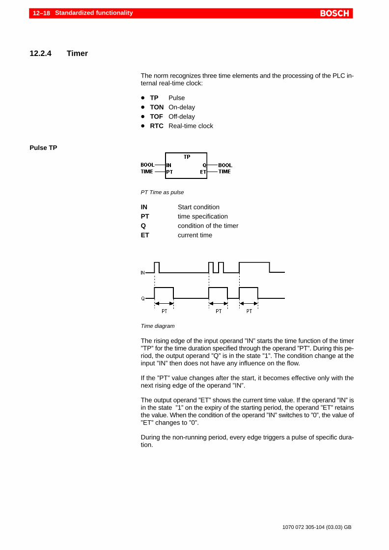
Standardized functionality12–18
1070 072 305-104 (03.03) GB
12.2.4 Timer
The norm recognizes three time elements and the processing of the PLC in-ternal real-time clock:
D TP PulseD TON On-delayD TOF Off-delayD RTC Real-time clock
Pulse TP
PT Time as pulse
IN Start conditionPT time specificationQ condition of the timerET current time
Time diagram
The rising edge of the input operand ”IN” starts the time function of the timer”TP” for the time duration specified through the operand ”PT”. During this pe-riod, the output operand ”Q” is in the state ”1”. The condition change at theinput ”IN” then does not have any influence on the flow.
If the ”PT” value changes after the start, it becomes effective only with thenext rising edge of the operand ”IN”.
The output operand ”ET” shows the current time value. If the operand ”IN” isin the state ”1” on the expiry of the starting period, the operand ”ET” retainsthe value. When the condition of the operand ”IN” switches to ”0”, the value of”ET” changes to ”0”.
During the non-running period, every edge triggers a pulse of specific dura-tion.

Standardized functionality 12–19
1070 072 305-104 (03.03) GB
On-delay TON
TON: On-delay
IN Start conditionPT time specificationQ condition of the timerET current time
Time diagram
The rising edge of the input operand ”IN” starts the time function of the timer”TON” for the time duration specified through the operand ”PT”. During therunning period, the output operand ”Q” is in the state ”0”. After the expiry ofthe starting period, the condition changes to ”1” and the same is maintaineduntil the operand ”IN” changes to ”0”.
If the ”PT” value changes after the start, it becomes effective only with thenext rising edge of the operand ”IN”.
The output operand ”ET” shows the current time value. If the started time isexpired, the operand ”ET” retains the value so long as the operand ”IN” is inthe state ”1”. When the condition of the operand ”IN” switches to ”0”, the va-lue of ”ET” changes to ”0”. If the condition of the operand ”IN” changes whilethe time runs to ”0”, the process is interrupted and the operand ”ET” againassumes the value ”0”. The switching on at the input ”IN” switches on theoutput ”Q” delayed by the specified time duration.
Off–delay TOF
TOF: Off-delay
IN Start conditionPT time specificationQ condition of the timerET Expiring time

Standardized functionality12–20
1070 072 305-104 (03.03) GB
Time diagram
The state ”1” of the input operand ”IN” is transferred without delay to the out-put operand ”Q”. The falling edge of the ”IN” starts the time function for thetime duration specified through the operand ”PT”. The condition change atthe input ”IN” to “0” then does not have any influence on the flow. After thetime expires, the operand ”Q” changes to the state ”0”.
If the ”PT” value changes after the start, it becomes effective only with thenext rising edge of the operand ”IN”.
The output operand ”ET” shows the current time value. If the started time isexpired, the operand ”ET” retains the value so long as the operand ”IN” is inthe state ”1”. When the condition of the operand ”IN” switches to ”0”, the va-lue of ”ET” changes to ”0”. The switching off at the input ”IN” switches off theoutput ”Q” delayed by the specified time duration.
Real-time clock RTC
RTC: Real-time clock
EN Set condition (not in function)PDT Set value for the real-time clock (not in function)Q Display of the current value of ENCDT Current date and time
The output operand ”Q” indicates the condition of ”EN”. The current time sta-tus is outputted through the operand ”CTD”.
. The IEC allows the setting of the PLC internal real-time clock with thefunction block RTC. In case of Bosch, RTC can be used only for rea-ding the real-time clock. The setting must take place using the corres-ponding system command in the WinSPS editor or monitor. RTC doesnot work with milliseconds.

Standard fulfilment 13–1
1070 072 305-104 (03.03) GB
13 Standard fulfilment
The following conformity tables as per IEC 61131-3 are used as checklistsfor evaluating the standard fulfillment. They demonstrate the characteristicsof the WinSPS programming system. For the classical programming langua-ges Bosch-IL, LD, FBD and SFC , the statements do not apply or apply onlyto a limited extent. The numbering in the tables are identical to the numbe-ring in the IEC 61131-3.
The Bosch programming system WinSPS has the “Base Level Certificate”for the programming language ST.
13.1 Common elements
Character set characteristics (table 1)
No. Explanation Yes No
1 Required character set x
2 Lowercase letters x
3a
3b
Hash sign (#)or
Pound sign
x
x
4a
4b
Dollar sign ($)orCurrency symbol
x
x
5a
5b
Vertical bar (|) orExclamation sign (!) x
x
6a
6b
Indexing delimiter:Square brackets [ ] orParenthesis ( )
x
x
Identifier characteristics (table 2)
No. Explanation Yes No
1 Uppercase letters and figures x
2 Uppercase and lowercase letters, figures, em-bedded understrokes
x
3 Uppercase and lowercase letters, figures, leadingand embedded understrokes
x
Comment characteristics (table 3)
No. Explanation Yes No
1 Comments x

Standard fulfilment13–2
1070 072 305-104 (03.03) GB
Numeric literals (table 4)
No. Explanation Yes No
1 Integer literals x
2 Real literals x
3 Real literals with exponents x
4 Binary literals x
5 Octal literals x
6 Hexadecimal literals x
7 Boolean zero and one x
8 Boolean FALSE and TRUE x
Characteristics of string literals (Table 5)
No. Explanation Yes No
1 Empty string (zero length)
String of length 1 with character A
String of length 1 with space
String of length one with a quotation mark
String of length 2 with CR and LF character
String of length 5, printed as “$1.00”
x
x
x
x
x
x
2 Character combinations in strings (table 6)
No. Explanation Yes No
2 Dollar sign ($$) x
3 Single quotation mark ($’) x
4 Linefeed ($L or $l) x
5 New line ($N or $n) x
6 New page ($P or $p) x
7 Carriage return ($R or $r) x
8 Tab ($T or $t) x

Standard fulfilment 13–3
1070 072 305-104 (03.03) GB
Time duration literal characteristics (table 7)
No. Explanation Yes No
1a1b
Time duration literals without understroke:
Short prefixLong prefix
xx
2a2b
Time duration literals with understroke:
Short prefixLong prefix
xx
Literals for date and time (table 8)
No. Explanation Yes No
1 Literals for date (long prefix: DATE#) x
2 Literals for date (short prefix: D# x
3 Literals for time of day (long prefix:TIME_OF_DAY#)
x
4 Literals for time of day (short prefix: TOD#) x
5 Literals for date and time(Long prefix: DATE_AND_TIME#)
x
6 Literals for date and time (short prefix: DT#) x

Standard fulfilment13–4
1070 072 305-104 (03.03) GB
Elementary data types (table 10)
No. Keyword Data Type Yes No
1 BOOL Boolean x
2 SINT Short integer x
3 INT Integer x
4 DINT Double integer x
5 LINT Long integer x
6 USINT Unsigned short integer x
7 UINT Unsigned integer x
8 UDINT Unsigned double integer x
9 ULINT Unsigned long integer x
10 REAL Real number x
11 LREAL Long real number x
12 TIME Time duration x
13 DATE (only) date x
14 TIME_OF_DAY orTOD
(only) time x
15 DATE_AND_TIME or TD
Date and time x
16 STRING Variable length string x
17 BYTE Bit string of length 8 x
18 WORD Bit string of length 16 x
19 DWORD Bit string of length 32 x
20 LWORD Bit string of length 64 x
Characteristics of data type declaration (table 12)
No. Characteristics of data type declarations Yes No
1 Direct derivation of elementary data types x
2 Data types for enumeration types x
3 Data type for range x
4 Data type for array x
5 Data type for structures x

Standard fulfilment 13–5
1070 072 305-104 (03.03) GB
Preset initial value (table 13)
Explanation Initialization value Yes No
BOOL, SINT, INTDINT, LINT,
0 x
USINT, UINT,UDINT, ULINT
0 x
BYTE, WORD,DWORD, LWORD
0 x
REAL, LREAL 0.0 x
TIME T#0s x
DATE D#0001-01-01 x
TIME_OF_DAY TOD#00:00:00 x
DATE_AND_TIME DT#0001-01-01-00:00:00 x
STRING ”(the empty string) x
Characteristics of the initial values of data types(Table 14)
No. Explanation Yes No
1 Initialization of directly derived types x
2 Initialization of data types for enumeration x
3 Initialization of data types for sub-range x
4 Initialization of data types for array x
5 Initialization of data types for structure x
6 Initialization of data types for derived structure x
Characteristics of prefix for memory area and size for directly dis-played variables (Table 15)
No. Explanation Yes No
1 I: Memory area input x
2 Q: Memory area output x
3 M Memory area label x
4 X: Single bit size x
5 None: Single bit size x
6 B: Byte size x
7 W Word size x
8 D Double word size x
9 L: Long word size x

Standard fulfilment13–6
1070 072 305-104 (03.03) GB
Keywords for variable declaration (table 16)
Key word Yes No
VAR x
VAR_INPUT x
VAR_OUTPUT x
VAR_IN_OUT x
VAR_EXTERNAL x
VAR_GLOBAL x
VAR_ACCESS x
RETAIN x
CONSTANT x
AT x
Characteristics of type assignment for variable (table 17)
No. Explanation Yes No
1 Declaration of directly displayed non-buffered vari-ables
x
2 Declaration of directly displayed buffered variables x
3 Declaration of memory area in case of symbolicvariables
x
4 Assignment of memory area in case of array x
5 Automatic memory allocation for symbolic variable x
6 Declaration for array x
7 Declaration for buffered array x
8 Declaration for structured variables x
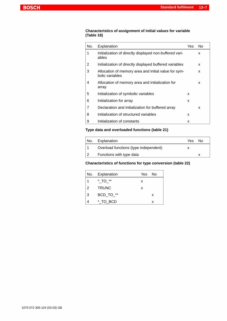
Standard fulfilment 13–7
1070 072 305-104 (03.03) GB
Characteristics of assignment of initial values for variable (Table 18)
No. Explanation Yes No
1 Initialization of directly displayed non-buffered vari-ables
x
2 Initialization of directly displayed buffered variables x
3 Allocation of memory area and initial value for sym-bolic variables
x
4 Allocation of memory area and initialization forarray
x
5 Initialization of symbolic variables x
6 Initialization for array x
7 Declaration and initialization for buffered array x
8 Initialization of structured variables x
9 Initialization of constants x
Type data and overloaded functions (table 21)
No. Explanation Yes No
1 Overload functions (type independent) x
2 Functions with type data x
Characteristics of functions for type conversion (table 22)
No. Explanation Yes No
1 *_TO_** x
2 TRUNC x
3 BCD_TO_** x
4 *_TO_BCD x
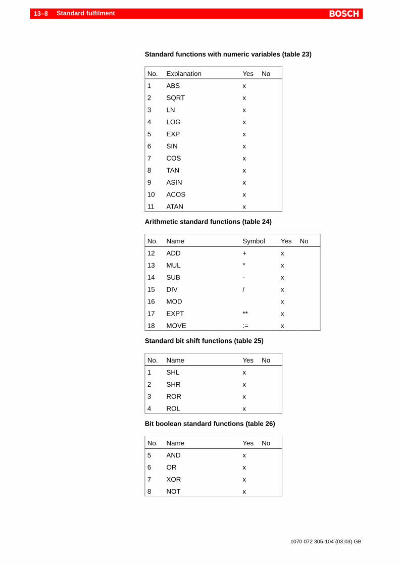
Standard fulfilment13–8
1070 072 305-104 (03.03) GB
Standard functions with numeric variables (table 23)
No. Explanation Yes No
1 ABS x
2 SQRT x
3 LN x
4 LOG x
5 EXP x
6 SIN x
7 COS x
8 TAN x
9 ASIN x
10 ACOS x
11 ATAN x
Arithmetic standard functions (table 24)
No. Name Symbol Yes No
12 ADD + x
13 MUL * x
14 SUB - x
15 DIV / x
16 MOD x
17 EXPT ** x
18 MOVE := x
Standard bit shift functions (table 25)
No. Name Yes No
1 SHL x
2 SHR x
3 ROR x
4 ROL x
Bit boolean standard functions (table 26)
No. Name Yes No
5 AND x
6 OR x
7 XOR x
8 NOT x

Standard fulfilment 13–9
1070 072 305-104 (03.03) GB
Standard functions for selection (table 27)
No. Name Yes No
1 SEL x
2a MAX x
2b MIN x
3 LIMIT x
4 MUX x
Standard functions for comparison (table 28)
No. Name Yes No
5 GT x
6 GE x
7 EQ x
8 LE x
9 LT x
10 NE x
Standard functions for strings (table 29)
No. Name Yes No
1 LEN x
2 LEFT x
3 RIGHT x
4 MID x
5 CONCAT x
6 INSERT x
7 DELETE x
8 REPLACE x
9 FIND x

Standard fulfilment13–10
1070 072 305-104 (03.03) GB
Functions for data types of time (table 30)
No. Name Operation Yes No
1
2
3
ADD TIME + TIME = TIME
TOD + TIME = TOD
DAT + TIME = DAT
x
x
x
4
5
6
7
8
9
SUB TIME - TIME = TIME
DATE - DATE = TIME
TOD - TIME = TOD
TOD - TOD = TIME
DAT - TIME = DAT
DAT - DAT = TIME
x
x
x
x
x
x
10
11
MUL
DIV
TIME * ANY_NUM = TIME
TIME / ANY_NUM = TIME
x
x
12 CONCAT DATE TOD = DAT x
13
14
Functions for type conversion
DATE_AND_TIME_TO_TIME_OF_DAY
DATE_AND_TIME_TO_DATE
x
x
Functions for data types of enumeration (table 31)
No. Name Yes No
1 SEL x
2 MUX x
3 EQ x
4 NE x

Standard fulfilment 13–11
1070 072 305-104 (03.03) GB
Characteristics of function block declaration (table 33)
No. Explanation Yes No
1 RETAIN for internal variables x
2 RETAIN for output variables x
3 RETAIN for internal function blocks x
4a Input/ output declaration (text form) x
4b Input/ output declaration (graphical) x
5a Function block instance name as input (text form) x
5b Function block instance name as input (graphical) x
6a Function block instance name as input/ output (textform)
x
6b Function block instance name as input/ output(graphical)
x
7a Function block instance name as external variable(text form)
x
7b Function block instance name as external variable(graphical)
x
8a
8b
Declaration in text form of inputs
With rising edge
With falling edge
x
x
9a
9b
Graphical declaration of inputs
With rising edge
With falling edge
x
x
Bistable standard functions (table 34)
No. Name Yes No
1 SR x
2 RS x
3 SEMA x
Standard function blocks edge detection (table 35)
No. Name Yes No
1 R_TRIG x
2 F_TRIG x
Standard function blocks counters (table 36)
No. Name Yes No
1 CTU x
2 CTD x
3 CTUD x

Standard fulfilment13–12
1070 072 305-104 (03.03) GB
Standard function blocks timer (table 37)
No. Name Yes No
1 TP (Puls) x
2a TON (on delay) x
2b T---0 (on delay) x
3a TOF (off delay) x
3b 0---T (off-delay) x
4 RTC (real time clock) x
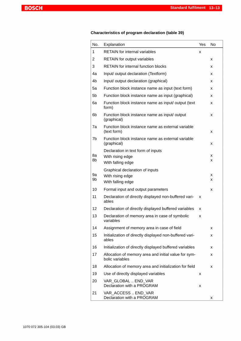
Standard fulfilment 13–13
1070 072 305-104 (03.03) GB
Characteristics of program declaration (table 39)
No. Explanation Yes No
1 RETAIN for internal variables x
2 RETAIN for output variables x
3 RETAIN for internal function blocks x
4a Input/ output declaration (Textform) x
4b Input/ output declaration (graphical) x
5a Function block instance name as input (text form) x
5b Function block instance name as input (graphical) x
6a Function block instance name as input/ output (textform)
x
6b Function block instance name as input/ output(graphical)
x
7a Function block instance name as external variable(text form) x
7b Function block instance name as external variable(graphical) x
8a8b
Declaration in text form of inputs
With rising edge
With falling edge
xx
9a9b
Graphical declaration of inputs
With rising edge
With falling edge
xx
10 Formal input and output parameters x
11 Declaration of directly displayed non-buffered vari-ables
x
12 Declaration of directly displayed buffered variables x
13 Declaration of memory area in case of symbolicvariables
x
14 Assignment of memory area in case of field x
15 Initialization of directly displayed non-buffered vari-ables
x
16 Initialization of directly displayed buffered variables x
17 Allocation of memory area and initial value for sym-bolic variables
x
18 Allocation of memory area and initialization for field x
19 Use of directly displayed variables x
20 VAR_GLOBAL .. END_VARDeclaration with a PROGRAM x
21 VAR_ACCESS .. END_VARDeclaration with a PROGRAM x

Standard fulfilment13–14
1070 072 305-104 (03.03) GB
13.2 Language elements
Operators of instructions list, IL (table 52)
No. Operator Modifier Yes No
1 LD N x
2 .ST N x
3 SR
xx
4 AND N,( x
5 & N,( x
6 OR N,( x
7 XOR N,( x
8 ADD ( x
9 SUB ( x
10 MUL ( x
11 DIV ( x
12 GT ( x
13 GE ( x
14 EQ ( x
15 NE ( x
16 LE ( x
17 LT ( x
18 JMP C, N x
19 CAL C, N x
20 RET C, N x
21 ) x
Characteristics of function block call in the language IL(Table 53)
No. Explanation Yes No
1 CAL with list of input parameters x
2 CAL with loading/ saving of input parameters x
3 Use of input operators x

Standard fulfilment 13–15
1070 072 305-104 (03.03) GB
Operators of language ST (table 55)
No. Explanation Yes No
1 Bracketing x
2 Function evaluation x
3 Exponentiation x
4 Negation x
5 Complement x
6 Multiplication x
7 Division x
8 Modulo x
9 Addition x
10 Subtraction x
11 Comparison x
12 Equality x
13 Inequalility x
14 Boolean AND x
15 Boolean AND x
16 Boolean exclusive OR x
17 Boolean OR x
Statements of language ST (table 56)
No. Explanation Yes No
2 Function block call and use of FB output x
3 RETURN x
4 IF x
5 CASE x
6 FOR x
7 WHILE x
8 REPEAT x
9 EXIT x
10 Empty statement x
1 RETAIN for internal variables x
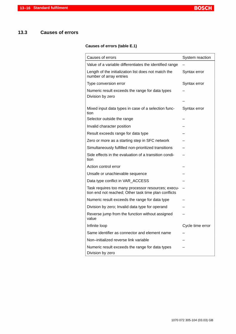
Standard fulfilment13–16
1070 072 305-104 (03.03) GB
13.3 Causes of errors
Causes of errors (table E.1)
Causes of errors System reaction
Value of a variable differentiates the identified range –
Length of the initialization list does not match thenumber of array entries
Syntax error
Type conversion error Syntax error
Numeric result exceeds the range for data types
Division by zero
–
–
Mixed input data types in case of a selection func-tion
Selector outside the range
Syntax error
–
Invalid character position –
Result exceeds range for data type –
Zero or more as a starting step in SFC network –
Simultaneously fulfilled non-prioritized transitions –
Side effects in the evaluation of a transition condi-tion
–
Action control error –
Unsafe or unachievable sequence –
Data type conflict in VAR_ACCESS –
Task requires too many processor resources; execu-tion end not reached; Other task time plan conflicts
–
Numeric result exceeds the range for data type –
Division by zero; Invalid data type for operand –
Reverse jump from the function without assignedvalue
–
Infinite loop Cycle time error
Same identifier as connector and element name –
Non–initialized reverse link variable –
Numeric result exceeds the range for data types
Division by zero
–

Annex A–1
1070 072 305-104 (03.03) GB
A Annex
A.1 Abbreviations
Abbreviation Description
DM Data Module
ESD Electro Static DischargeAbbreviation for all terms relating to elec-tro-static discharge, e.g. ESD protection,ESD hazards, etc.
FB FUNCTION_BLOCK acc. to IEC 61131-3
FBD Function Block Diagram
FC Function Call of the classical program lan-guages
FUN FUNCTION acc. to IEC 61131-3
IEC International Electrotechnical Commission
IL Instruction List
LD Ladder Diagram
OM Organisation Module
PCL Bosch Software PLC. The name is com-posed from PC (Personal Computer) andCL (Control Logic).
PLC Programmable Logic Controller
POU Program Organisation Unit
PROG PROGRAM, main program acc. toIEC61131-3
SFC Sequential Function Chart
ST Structured Text
WinSPS Bosch software for programming PLCs
AnnexA–2
1070 072 305-104 (03.03) GB
A.2 Index
AAccess paths, 6–10Accumulator, 8–2Actual parameter, 11–6Actual Result, 8–2Addition, 8–15Address, 5–5AND, 8–12ANDN, 8–12ANY, 7–13Arithmetic functions, 12–5Arithmetic operators, 8–15ARRAY, 7–22Array, 7–22ASCII constants, 7–5ASCII string, 7–10Assignment, 8–10, 9–4AT, 7–19Attributes, 5–6, 7–30
BBase byte address, 11–15Base Level Certificate, 3–8Base–specific number, 7–5Binary links, 12–8Binary numbers, 7–4Binary operations, 8–12Bistable elements, 8–11, 12–14Bit sequence , 7–10Body, 6–12BOOL, 7–10Boolean data, 7–4Boolean functions, 12–8Boolean operators, 8–12Bosch IL, 3–2, 11–4BYTE, 7–10
CCAL, 8–21CALC, 8–21CALCN, 8–21Calendar date, 7–6, 7–10Call interface, 6–14Call parameter list, 11–5call–by–reference, 6–15call–by–value, 6–15Carry, 8–2CASE, 9–7Causes of errors, 13–16Certificate, 3–8Check, 10–1Check module, 10–1Checklists, 13–1Classical programming language, 3–2, 11–1Cleaning up, 11–9Cold reset, 7–17Comment, 7–8Common elements, 3–5, 5–2, 13–1
Comparison, 12–9Comparison operators, 8–18Compile module, 10–1Compliance Tables, 13–1Conditional execution, 8–18, 9–5Conditional FB call, 8–21Conditional jump, 8–20Conditional return jump, 8–24Configuration, 3–7Conformity tables, 13–1CONSTANT, 7–30Constant definition, 5–18, 7–31Counter, 12–16Counting loop , 9–8CR, 8–2Create new project, 10–2CTD, 12–16CTU, 12–16CTUD, 12–17Current Result, 8–2
DData buffer, 11–12Data field, 11–12Data model, 7–1Data module, 4–4, 10–4Data structure, 7–28Data Type, 5–5, 5–9, 7–9Data type conversion, 12–3Data width, 7–19DATE, 7–10Date, 7–6DATE_AND_TIME, 7–10Declaration, 7–15Declaration part, 6–8Declaration tables, 5–3Default settings, 4–1Default value, 7–9DEFINE Editor, 5–18Delimiter, 7–7Derived data types, 7–11DINT, 7–10Directly shown address, 7–19Division, 8–17DM, 10–4, 11–6Documentation, 1–6Downward counter , 12–16DWORD, 7–10
EEdge detection, 12–15Elementary data types, 7–9ELSE, 9–6, 9–7ELSEIF, 9–6Emergency–STOP–devices, 1–5End Of Line, 7–7End section, 10–4Entire program, 10–2

Annex A–3
1070 072 305-104 (03.03) GB
ENUM, 5–16, 7–12Enumeration, 7–12Error messages, 5–12Exclusive OR:, 8–14EXIT, 9–12Exponential numbers, 7–5Extensibility , 12–3External variable, 6–10
FF_EDGE, 7–30F_TRIG, 12–15Falling edge, 12–15FALSE, 7–10FB, refer to: Function block, 6–5FBD, 3–1FC, 10–4Figure with a sign, 7–10Figure without a sign, 7–10Firmware version, 3–8Flipflop, 8–11, 12–14Floating point numbers, 7–4, 7–10Floppy disk drive, 1–6FOR, 9–8Formal parameter, 6–14FUN, refer to: Function, 6–7FUN ReturnType, 5–4FUNCTION, 6–7Function, 6–7
Call, 6–19, 8–22Extensibility , 12–3Overloaded, 12–1Standard functions, 12–1
Function block, 6–5Call, 6–17, 8–20, 11–5Changing the call, 11–8Deleting the call, 11–9Instance, 6–21Memory, 6–22Standard function block, 12–12Validity, 6–22
Function Block Diagram, 3–1Function value, 6–14FUNCTION_BLOCK, 6–5
GGate, 8–12Generate project, 10–2Generic data types, 7–13, 12–1Global type definition, 5–14, 11–14Global variable, 6–10GRAFCET, 3–3
HHard disk drive, 1–6Hexadecimal numbers, 7–4Hot Restart, 7–17
IIdentifiers, 7–3, 11–17IEC 61131–3, 3–1
IEC file, 4–4IEC IL, 3–2IEC_FUNCTION_BLOCK, 11–9IF, 9–6IL, 3–1, 8–1
Current Result, 8–2Instruction set, 8–7Instructions, 8–1Label, 8–5Nesting, 8–5Sequence, 8–4
IM, 10–4Initial value, 5–5, 5–10, 6–15, 7–11, 7–16Initializing the PCL, 7–9, 7–16Input and output variable, 6–10Input parameter, 6–14Input variable, 6–9Inputs, 7–19Installation, 4–1Instance, 6–21, 6–22, 10–6, 11–4Instruction list, refer to: IL, 8–1Instruction set, 8–7Instructions
IL, 8–1ST, 9–3
Instructions part, 5–11, 6–12INT, 7–10Interrupt, 8–2Iterations, 9–5
JJMP, 8–19JMPC, 8–20JMPCN, 8–20Jump statements, 8–19, 9–3
KKey words, 7–2
LLabel, 8–1, 8–5Ladder Diagram, 3–1Language elements, 7–1, 13–14LD, 3–1, 8–9LDN, 8–9Library, 6–6, 6–8License, 4–1Link, 8–12Link modules, 10–2Linker, 10–2Links, 12–8LINT, 7–9Literals, 7–4Load instructions, 8–9Load modules, 10–5Load program, 10–5Local variable, 6–9Logical links, 12–8Logical operations, 8–12Logical value, 7–10LREAL, 7–10
AnnexA–4
1070 072 305-104 (03.03) GB
LWORD, 7–9
MMain program, 6–4, 10–2Marker, 7–19Mathematical operators, 8–15Memory, 6–22Memory address, 11–15Mixed programs, 11–2Module Calls, 6–12Modules, 6–1Monitor, 10–6Monitor data, 5–7Multi–selection, 9–7Multielement variables, 7–22Multiplication, 8–16Multitasking, 6–4
NNames, 7–2Negation, 8–2Nesting levels, 8–5Number base, 7–5Numbers, 7–4Numeric functions, 12–5Numeric literals, 7–4
OOctal numbers, 7–4Off–delay, 12–19OM1, 11–2On–delay, 12–19Operand, 8–2Operator, 8–2Operators
Arithmetic, 8–15Assignment, 8–10Boolean, 8–12Call of FBs, 8–20Comparison, 8–18IL (Programming language), 8–7Jump, 8–19Load instructions, 8–9Return jump, 8–23ST (Programming language), 9–1
OR, 8–13Order of precedence, 9–1Organisation module, 11–2ORN, 8–13Output parameter, 6–14Output variable, 6–9Outputs, 7–19Overflow, 8–2Overloaded function, 7–14, 12–1
PParameter, 6–14Parethesis, 8–5Physical addresses, 5–5, 7–19, 11–11, 11–17PLC addresses, 7–19PM, 11–6
Pointer, 6–15, 11–16Post–loading, 10–5POU, 6–1
Call parameter, 6–14Calls, 6–12
POU name, 5–3POU type, 5–3, 6–3Power failure, 7–17Priority, 9–1PROG, 6–4PROGRAM, 6–4Program file, 4–3, 10–4Program module, 4–3, 11–2Program Organization Units, refer to: POU, 6–1Programming languages, 3–1Project specifications, 10–4Pulse, 12–18
QQualified personnel, 1–2Quotation marks, 7–5
RR, 8–11R_EDGE, 7–30R_TRIG, 12–15RANGE, 7–12Range, 7–12READ_ONLY, 7–30READ_WRITE, 7–30REAL, 7–10Real time clock, 12–20Recursion, 6–13Register, 8–2Release, 1–6Remanence characteristic, 7–17REPEAT, 9–10Reset dominant, 12–14Resetting command, 12–14Resetting instruction, 8–11Resource, 3–7Restart, 7–17Result of logic operations, 8–2RET, 8–23RETAIN, 7–17, 7–30RETC, 8–24RETCN, 8–24RETURN, 9–5Return jump, 8–23, 9–5Return value, 6–14return–by–value, 6–15Rising edge, 12–15RLO, 8–2Rotate, 12–7RS, 12–14RTC, 12–20
SS, 8–10Safety instructions, 1–4Safety markings, 1–3

Annex A–5
1070 072 305-104 (03.03) GB
Selection, 9–5, 9–6, 12–8Sequential Function Chart, 3–1, 11–10Set dominant, 12–14Set instruction, 8–10Setting command, 12–14SFC, 3–1Shift, 12–7Sign, 7–5Single element variable, 7–22SINT, 7–10Software version, 3–8Space, 7–7Special characters, 7–5, 7–7Special marker, 11–12SR, 12–14ST, 8–10, 9–1
Assignment, 9–4Expressions, 9–1Function block call, 9–4Function call, 9–2Instructions, 9–3Loop end, 9–12Loops, 9–8Operands, 9–1Operators, 9–1Priority, 9–1Return jump, 9–5Selection, 9–6, 9–7
Standard fulfillment, 13–1Standard function block, 12–12
Bistable elements, 12–14Counter, 12–16Edge detection, 12–15Timer, 12–18
Standard functions, 12–1Arithmetic, 12–5Shift, 12–7Boolean, 12–8Comparison, 12–9Numeric, 12–5Selection, 12–8Strings, 12–10Type conversion, 12–3
Standard operation, 1–1Standard value, 7–9Start section, 10–4Status bit, 8–2Step action, 11–10STN, 8–10STRING, 7–10String literal, 7–5String terminator, 7–5String variables, 7–21Strings, 11–17, 12–10STRUCT, 5–15, 7–28Structure, 7–28Structured Text, refer to: ST, 9–1Subtraction, 8–16Symbol file, 4–3, 10–4, 11–11Symbolic operands, 11–13
TTask, 3–7Terminator, 7–5Text constants, 7–12THEN, 9–6TIME, 7–10Time, 7–6, 7–10Time duration, 7–6, 7–10Time literals, 7–6Time of day, 7–6TIME_OF_DAY, 7–10Timer, 12–18TOF, 12–19TON, 12–19TP, 12–18Trademarks, 1–6Translate module, 10–1TRUE, 7–10TYPE, 5–14, 7–11Type conversion, 12–3Type definition, 5–8, 7–11Type editor, 5–14Type name, 5–8
UUDINT, 7–10UINT, 7–10ULINT, 7–9Umlauts, 7–1, 7–6Unconditional FB call, 8–21Unconditional jump, 8–19Unconditional return jump, 8–23Understroke, 7–3, 7–5, 7–6UNTIL, 9–10Upward and downward counter, 12–17Upward counter, 12–16USINT, 7–10
VValidity, 6–22VAR, 6–9VAR_ACCESS, 6–10VAR_EXTERNAL, 6–10VAR_GLOBAL, 6–10VAR_IN_OUT, 6–10VAR_INPUT, 6–9VAR_OUTPUT, 6–9Variable, 7–15
Access, 7–18ARRAY, 7–22Attributes, 7–30Data structure (STRUCT), 7–28Initialization, 7–16Physical address, 7–19String, 7–21
Variable attributes, 7–30Variable declaration, 5–4Variable type, 5–4, 6–9, 6–15
WWarm start, 7–17

AnnexA–6
1070 072 305-104 (03.03) GB
WHILE, 9–10WORD, 7–10Working register, 8–2
XXOR, 8–14
ZZero, 8–2
A–1
1070 072 305-104 (03.03) GB
1070 072 305-104 (03.03) GB · HB SP · BRC/EPY · Printed in Germany
Bosch Rexroth AGElectric Drives and ControlsPostfach 11 6264701 ErbachBerliner Straße 2564711 ErbachDeutschlandTel.: +49 (0) 60 62/78-0Fax: +49 (0) 60 62/78-4 28www.boschrexroth.com
Australia
Bosch Rexroth Pty. Ltd.3 Valediction RoadKings Park NSW 2148Phone:+61 (0) 2 98 31 77 88Fax: +61 (0) 2 98 31 55 53
United Kingdom
Bosch Rexroth Ltd.Broadway Lane, South CerneyCirencester GL7 5UHPhone:+44 (0) 1285-86 30 00Fax: +44 (0) 1285-86 30 03
USA
Bosch Rexroth Corporation5150 Prairie Stone ParkwayHoffmann Estates, Illinois 60192Phone:+1 (0) 847 6 45-36 00Fax: +1 (0) 847 6 45-08 04
Canada
Bosch Rexroth Canada Corp.490 Prince Charles Drive SouthWelland, Ontario L3B 5X7Phone:+1 (0) 905 7 35-05 10Fax: +1 (0) 905 7 35-56 46