wireless and mobile networks - western illinois...
TRANSCRIPT
Wireless and Mobile Networks
Background: # wireless (mobile) phone subscribers now
exceeds # wired phone subscribers!
# wireless Internet-connected devices soon to exceed # wireline Internet-connected devices laptops, Internet-enabled phones promise anytime
untethered Internet access
two important (but different) challenges wireless: communication over wireless link
mobility: handling the mobile user who changes point of attachment to network
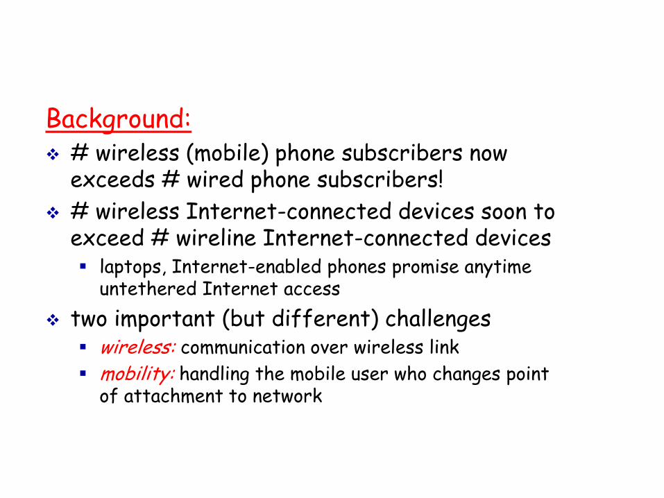
Elements of a wireless network
network infrastructure
wireless hosts laptop, PDA, IP phone run applications may be stationary
(non-mobile) or mobile wireless does not
always mean mobility
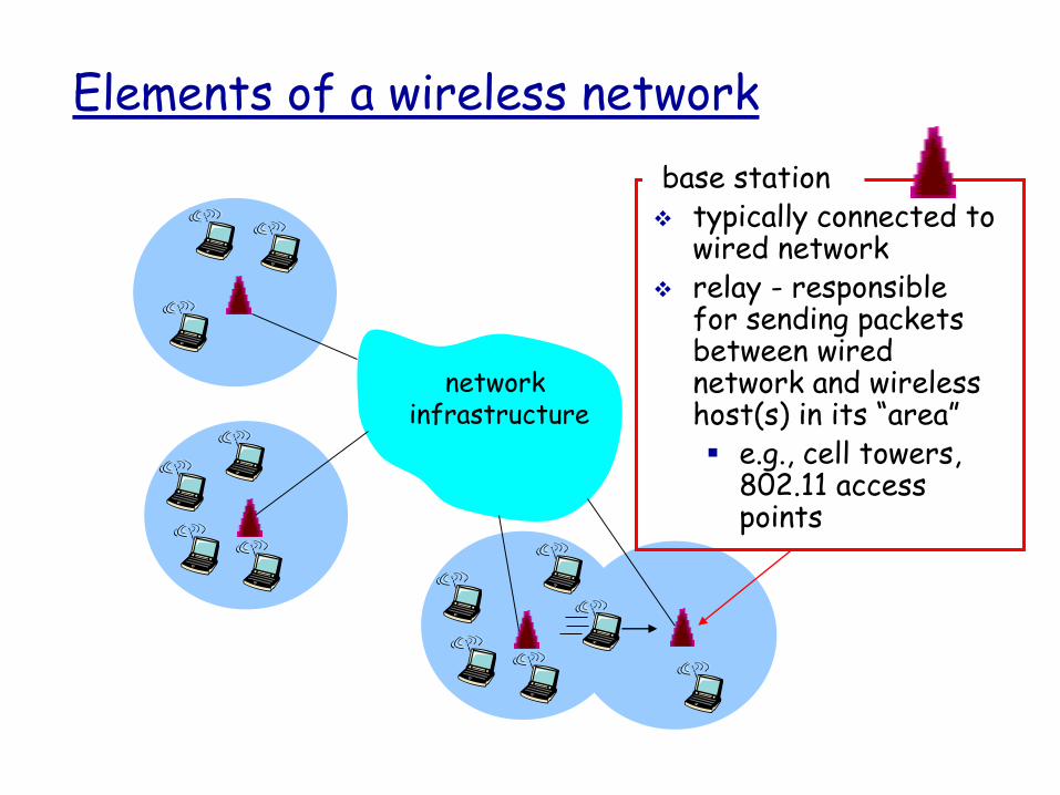
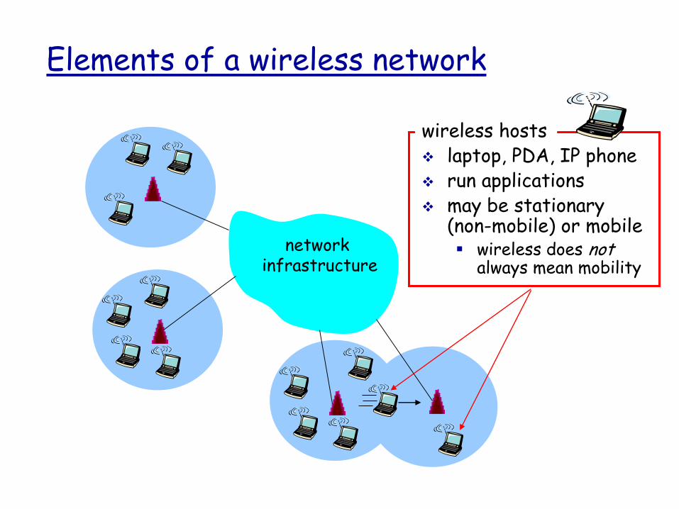
Elements of a wireless network
network infrastructure
base station typically connected to
wired network relay - responsible
for sending packets between wired network and wireless host(s) in its “area” e.g., cell towers,
802.11 access points
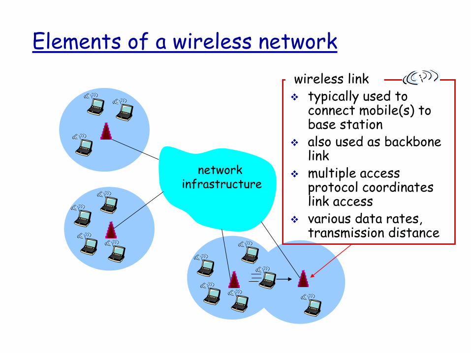
Elements of a wireless network
network infrastructure
wireless link typically used to
connect mobile(s) to base station
also used as backbone link
multiple access protocol coordinates link access
various data rates, transmission distance

Characteristics of selected wireless link standards
Indoor10-30m
Outdoor50-200m
Mid-range
outdoor200m – 4 Km
Long-range
outdoor5Km – 20 Km
.056
.384
1
4
5-11
54
IS-95, CDMA, GSM 2G
UMTS/WCDMA, CDMA2000 3G
802.15
802.11b
802.11a,g
UMTS/WCDMA-HSDPA, CDMA2000-1xEVDO 3G cellular
enhanced
802.16 (WiMAX)
802.11a,g point-to-point
200 802.11n
Data
rate
(M
bps) data
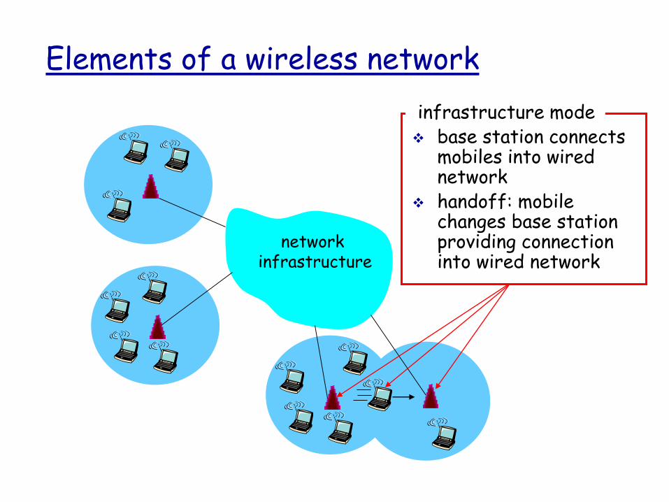
Elements of a wireless network
network infrastructure
infrastructure mode base station connects
mobiles into wired network
handoff: mobile changes base station providing connection into wired network

Elements of a wireless network
ad hoc mode no base stations nodes can only
transmit to other nodes within link coverage
nodes organize themselves into a network: route among themselves

Wireless network taxonomy
single hop multiple hops
infrastructure(e.g., APs)
noinfrastructure
host connects to base station (WiFi,WiMAX, cellular) which connects to
larger Internet
no base station, noconnection to larger Internet (Bluetooth,
ad hoc nets)
host may have torelay through several
wireless nodes to connect to larger
Internet: mesh net
no base station, noconnection to larger
Internet. May have torelay some other
nodes to reach a dest.MANET, VANET

Wireless Link Characteristics (1)
Differences from wired link ….
decreased signal strength: radio signal attenuates as it propagates through matter (path loss)
interference from other sources: standardized wireless network frequencies (e.g., 2.4 GHz) shared by other devices (e.g., phone); devices (motors) interfere as well
multipath propagation: radio signal reflects off objects, ground, arriving at destination at slightly different times
…. make communication across (even a point to point) wireless link much more “difficult”

Wireless, Mobile Networks 6-11
Signal propagation ranges
Transmission range
- communication possible
- low error rate
Detection range
- detection of the signal possible
- no communication possible
Interference range
- signal may not be detected
- signal adds to the background
noise
distance
sender
transmission
detection
interference

Wireless, Mobile Networks 6-12
Signal propagation
Propagation in free space always like light (straight line)
Receiving power proportional to 1/d² in vacuum – much more in real
environments (d = distance between sender and receiver)
Receiving power additionally influenced by
- fading (frequency dependent)
- shadowing
- reflection at large obstacles
- refraction depending on the density of a medium
- scattering at small obstacles
- diffraction at edges
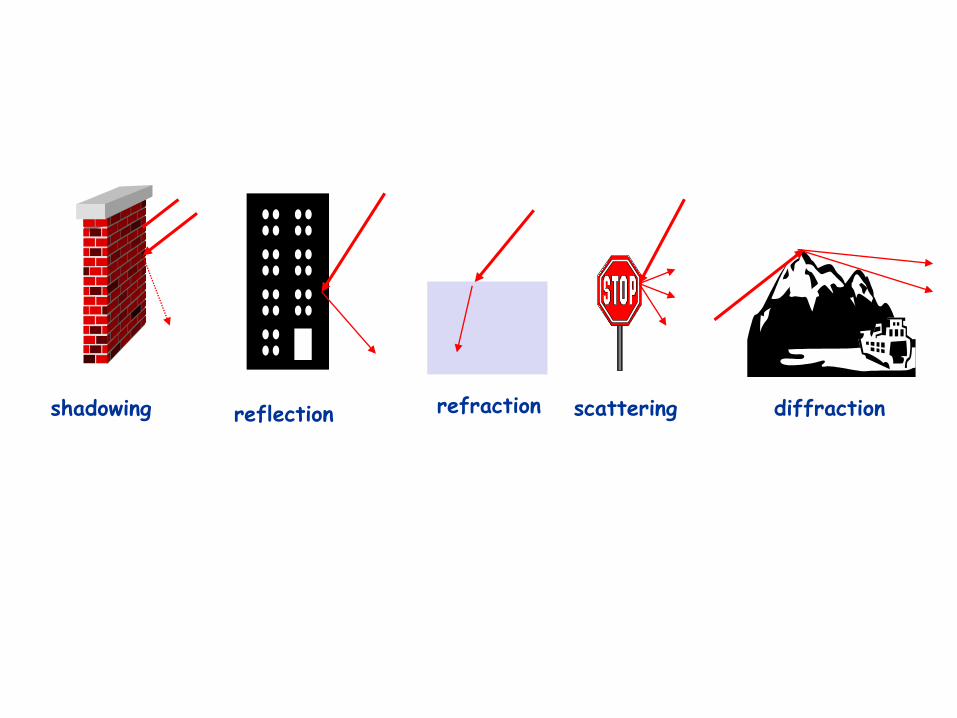
reflection scattering diffractionshadowing refraction
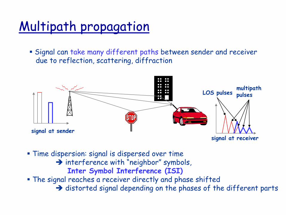
Multipath propagation
Signal can take many different paths between sender and receiver due to reflection, scattering, diffraction
signal at sendersignal at receiver
LOS pulsesmultipathpulses
Time dispersion: signal is dispersed over time interference with “neighbor” symbols,
Inter Symbol Interference (ISI) The signal reaches a receiver directly and phase shifted
distorted signal depending on the phases of the different parts
Wireless, Mobile Networks 6-15
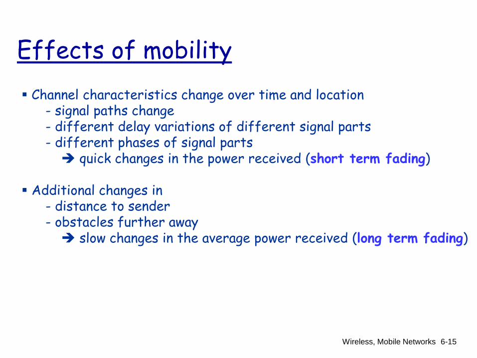
Effects of mobility
Channel characteristics change over time and location - signal paths change- different delay variations of different signal parts- different phases of signal parts quick changes in the power received (short term fading)
Additional changes in- distance to sender- obstacles further away slow changes in the average power received (long term fading)
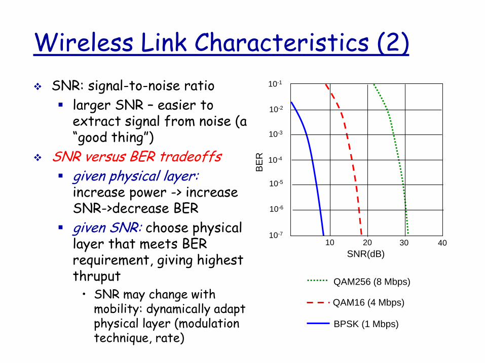
Wireless Link Characteristics (2)
SNR: signal-to-noise ratio
larger SNR – easier to extract signal from noise (a “good thing”)
SNR versus BER tradeoffs given physical layer:
increase power -> increase SNR->decrease BER
given SNR: choose physical layer that meets BER requirement, giving highest thruput
• SNR may change with mobility: dynamically adapt physical layer (modulation technique, rate)
10 20 30 40
QAM256 (8 Mbps)
QAM16 (4 Mbps)
BPSK (1 Mbps)
SNR(dB)B
ER
10-1
10-2
10-3
10-5
10-6
10-7
10-4

Digital modulation
Modulation of digital signals known as Shift Keying
Amplitude Shift Keying (ASK)- very simple- low bandwidth requirements- very susceptible to interference
Frequency Shift Keying (FSK)- needs larger bandwidth
Phase Shift Keying (PSK)- more complex- robust against interference
1 0 1
t
1 0 1
t
1 0 1
t

Advanced Frequency Shift Keying
special pre-computation avoids sudden phase shifts MSK (Minimum Shift Keying)
bit separated into even and odd bits, the duration of each bit is
doubled
depending on the bit values (even, odd) the higher or lower
frequency, original or inverted is chosen
the frequency of one carrier is twice the frequency of the other
(f2=2f1)
even higher bandwidth efficiency using a Gaussian low-pass filter
GMSK (Gaussian MSK), used in GSM

Example of MSK
data
even bits
odd bits
1 0 1 0 111
t
low
frequency
high
frequency
MSK
signal

Advanced Phase Shift Keying
BPSK (Binary Phase Shift Keying)
- bit value 0: sine wave
- bit value 1: inverted sine wave
- very simple PSK
- low spectral efficiency
- robust, used in satellite systems
QPSK (Quadrature Phase Shift Keying)
- 2 bits coded as one symbol
- symbol determines shift of sine wave
- needs less bandwidth compared to BPSK
- more complex
DQPSK - Differential QPSK (IS-136, PHS)
- Phase shift is not relative to a reference
signal but to the phase of the previous two bits
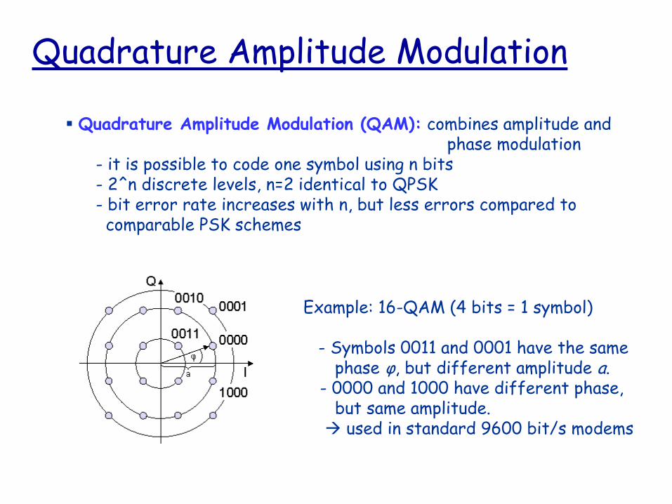
Quadrature Amplitude Modulation
Quadrature Amplitude Modulation (QAM): combines amplitude and phase modulation
- it is possible to code one symbol using n bits- 2^n discrete levels, n=2 identical to QPSK- bit error rate increases with n, but less errors compared to comparable PSK schemes
Example: 16-QAM (4 bits = 1 symbol)
- Symbols 0011 and 0001 have the samephase φ, but different amplitude a.
- 0000 and 1000 have different phase,but same amplitude. used in standard 9600 bit/s modems

Wireless network characteristicsMultiple wireless senders and receivers create
additional problems (beyond multiple access):
AB
C
Hidden terminal problem B, A hear each other B, C hear each other A, C can not hear each othermeans A, C unaware of their
interference at B
A B C
A’s signalstrength
space
C’s signalstrength
Signal attenuation: B, A hear each other B, C hear each other A, C can not hear each other
interfering at B

MACA - collision avoidanceMACA (Multiple Access with Collision Avoidance) uses short signaling packets for collision avoidance
RTS (request to send): a sender request the right to
send from a receiver with a short RTS packet before it
sends a data packet
CTS (clear to send): the receiver grants the right to send
as soon as it is ready to receive
Signaling packets contain
sender address
receiver address
packet size
Variants of this method can be found in IEEE802.11 as DFWMAC (Distributed Foundation Wireless MAC)

MACA examples
MACA avoids the problem of hidden terminals
A and C want to send to A sends RTS first C waits after receiving CTS
from B
MACA avoids the problem of exposed terminals
B wants to send to A, C to another terminal now C does not have to wait for
it cannot receive CTS from A

MACA variant: DFWMAC in IEEE802.11

Multiplexing
Multiplexing in 4 dimensions- space (si)- time (t)- frequency (f)- code (c)
Goal: multiple use of a shared medium
Important: guard spaces needed!

Frequency multiplex
Separation of the whole spectrum into smaller frequency bandsA channel gets a certain band of the spectrum for the whole time
Advantages:- no dynamic coordination necessary- works also for analog signals
Disadvantages:- waste of bandwidth if the traffic is distributed unevenly- inflexible- guard spaces

Frequency multiplex
k2 k3 k4 k5 k6k1
f
t
c

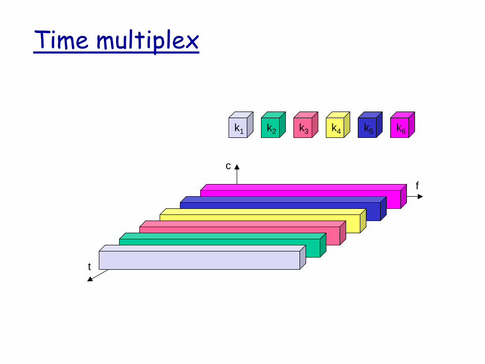
Time multiplex
A channel gets the whole spectrum for a certain amount of time
Advantages:- only one carrier in the medium at any time- throughput high even for many users
Disadvantages:- precise synchronization necessary
Time multiplex
f
t
c
k2 k3 k4 k5 k6k1
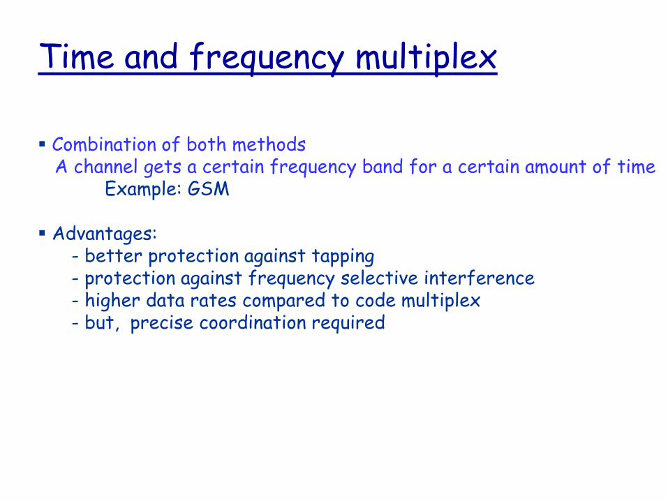
Time and frequency multiplex
Combination of both methodsA channel gets a certain frequency band for a certain amount of time
Example: GSM
Advantages:- better protection against tapping- protection against frequency selective interference- higher data rates compared to code multiplex- but, precise coordination required

Time and frequency multiplex
f
t
c
k2 k3 k4 k5 k6k1
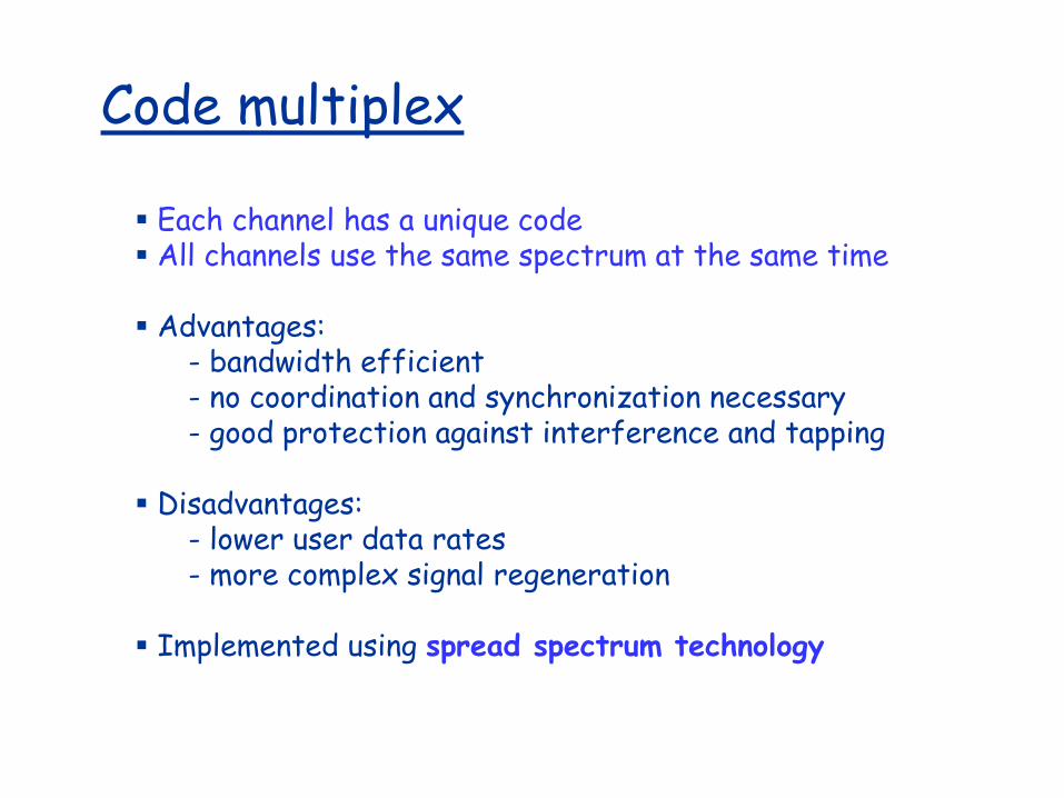
Code multiplex
Each channel has a unique code All channels use the same spectrum at the same time
Advantages:- bandwidth efficient- no coordination and synchronization necessary- good protection against interference and tapping
Disadvantages:- lower user data rates- more complex signal regeneration
Implemented using spread spectrum technology

k2 k3 k4 k5 k6k1
f
t
c
Code Multiplex

Code Division Multiple Access (CDMA)
used in several wireless broadcast channels (cellular, satellite, etc) standards
unique “code” assigned to each user; i.e., code set partitioning
all users share same frequency, but each user has own “chipping” sequence (i.e., code) to encode data
encoded signal = (original data) X (chipping sequence)
decoding: inner-product of encoded signal and chipping sequence
allows multiple users to “coexist” and transmit simultaneously with minimal interference (if codes are “orthogonal”)

Advantages:
all terminals can use the same frequency, no planning needed
huge code space (e.g. 232) compared to frequency space
interferences (e.g. white noise) is not coded
forward error correction and encryption can be easily integrated
Disadvantages:
Higher complexity of a receiver (receiver cannot just listen into the medium and start receiving if there is a signal)
All signals should have the same strength at a receiver
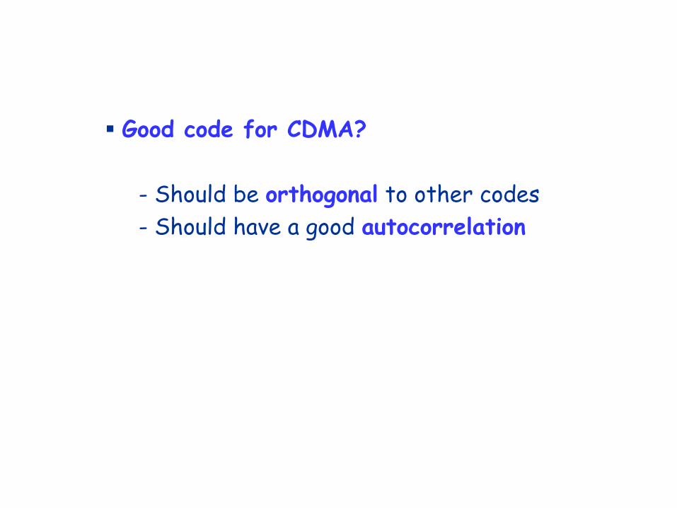
Good code for CDMA?
- Should be orthogonal to other codes
- Should have a good autocorrelation

Two vectors are called orthogonal if their inner product is 0.
1) Vectors (2, 5, 0) and (0, 0, 17) Orthogonal
(2, 5, 0) (0, 0, 17) = 0 + 0 + 0 = 0
Vectors (3, -2, 4) and (-2, 3, 3) Orthogonal
(3, -2, 4) (-2, 3, 3) = - 6 – 6 + 12 = 0
2) Vectors (1, 2, 3) and (4, 2, -6) Not orthogonal
(1, 2, 3) (4, 2, -6) = 4 + 4 – 18 = -10 ≠ 0
3) Vectors (1, 2, 3) and (4, 2, -3) Almost orthogonal
(1, 2, 3) (4, 2, -3) = 4 + 4 – 9 = -1 ≈ 0

CDMA Encode/Decode
slot 1 slot 0
d1 = -1
1 1 1 1
1- 1- 1- 1-
Zi,m= di.cm
d0 = 1
1 1 1 1
1- 1- 1- 1-
1 1 1 1
1- 1- 1- 1-
1 1 11
1-1- 1- 1-
slot 0
channel
output
slot 1
channel
output
channel output Zi,m
sendercode
data
bits
slot 1 slot 0
d1 = -1
d0 = 1
1 1 1 1
1- 1- 1- 1-
1 1 1 1
1- 1- 1- 1-
1 1 1 1
1- 1- 1- 1-
1 1 11
1-1- 1- 1-
slot 0
channel
output
slot 1
channel
outputreceiver
code
received
input
Di = S Zi,m.cm
m=1
M
M

CDMA: two-sender interference
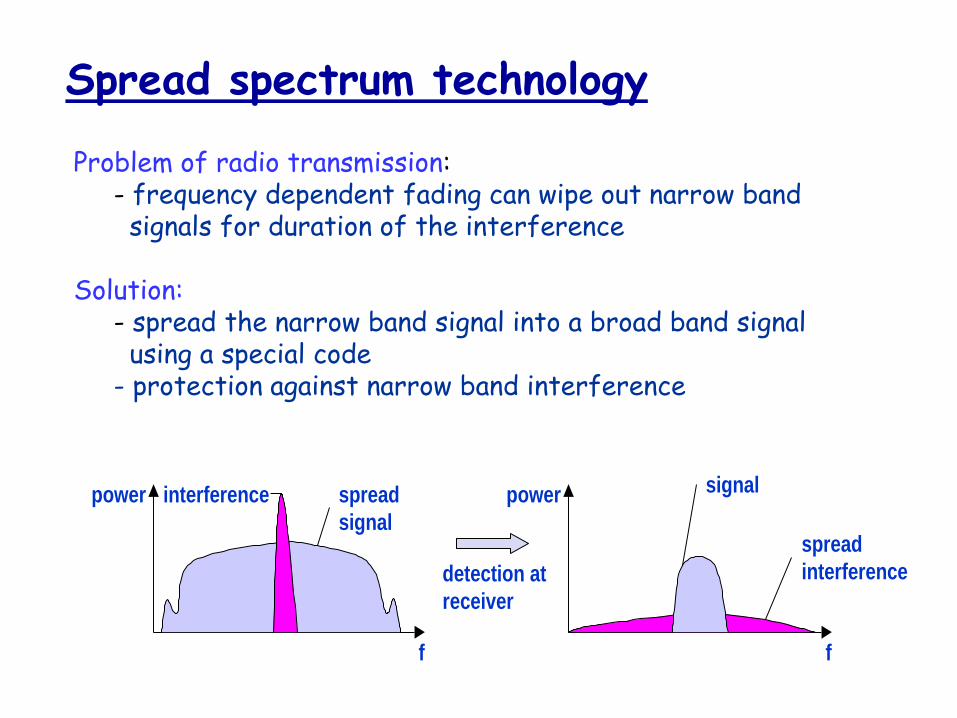
Spread spectrum technology
Problem of radio transmission: - frequency dependent fading can wipe out narrow band
signals for duration of the interference
Solution:- spread the narrow band signal into a broad band signal
using a special code - protection against narrow band interference
detection at
receiver
interference spread
signal
signal
spread
interference
f f
power power
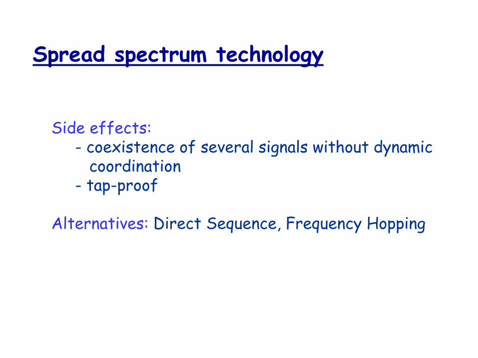
Spread spectrum technology
Side effects:- coexistence of several signals without dynamic
coordination- tap-proof
Alternatives: Direct Sequence, Frequency Hopping

Effects of spreading and interference
dP/df
f
i)
dP/df
f
ii)
sender
dP/df
f
iii)
dP/df
f
iv)
receiverf
v)
user signal
broadband interference
narrowband interference
dP/df

Spreading and frequency selective fading
frequency
channel
quality
1 2
3
4
5 6
narrow band
signal
guard space
22
22
2
frequency
channel
quality
1
spread
spectrum
narrowband channels
spread spectrum channels
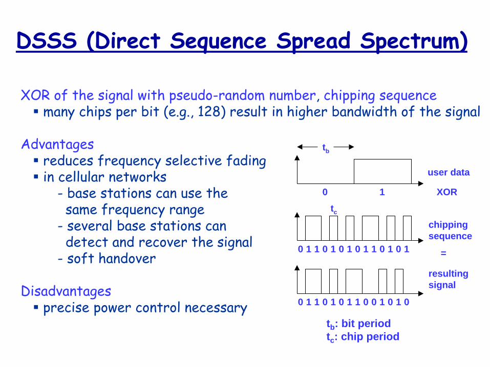
DSSS (Direct Sequence Spread Spectrum)
XOR of the signal with pseudo-random number, chipping sequence many chips per bit (e.g., 128) result in higher bandwidth of the signal
Advantages reduces frequency selective fading in cellular networks
- base stations can use the same frequency range
- several base stations candetect and recover the signal
- soft handover
Disadvantages precise power control necessary
user data
chipping
sequence
resulting
signal
0 1
0 1 1 0 1 0 1 01 0 0 1 11
XOR
0 1 1 0 0 1 0 11 0 1 0 01
=
tb
tc
tb: bit period
tc: chip period

DSSS (Direct Sequence Spread Spectrum)
X
user data
chipping
sequence
modulator
radio
carrier
spread
spectrum
signaltransmit
signal
transmitter
demodulator
received
signal
radio
carrier
X
chipping
sequence
lowpass
filtered
signal
receiver
integrator
products
decision
data
sampled
sums
correlator

FHSS (Frequency Hopping Spread Spectrum)
Discrete changes of carrier frequency sequence of frequency changes determined via pseudo random
number sequence
Two versions Fast Hopping: several frequencies per user bit Slow Hopping: several user bits per frequency
Advantages frequency selective fading and interference limited to short period simple implementation uses only small portion of spectrum at any time
Disadvantages not as robust as DSSS simpler to detect

FHSS (Frequency Hopping Spread Spectrum)
user data
slow
hopping
(3 bits/hop)
fast
hopping
(3 hops/bit)
0 1
tb
0 1 1 t
f
f1
f2
f3
t
td
f
f1
f2
f3
t
td
tb: bit period td: dwell time

FHSS (Frequency Hopping Spread Spectrum)
modulator
user data
hopping
sequence
modulator
narrowband
signal
spread
transmit
signal
transmitter
received
signal
receiver
demodulator
data
frequency
synthesizer
hopping
sequence
demodulator
frequency
synthesizer
narrowband
signal

IEEE 802.11 Wireless LAN
802.11b 2.4 GHz unlicensed spectrum
up to 11 Mbps
direct sequence spread spectrum (DSSS) in physical layer
• all hosts use same chipping code
802.11a 5 GHz range
up to 54 Mbps
802.11g 2.4 GHz range
up to 54 Mbps
802.11n: multiple antennae
2.4-5 GHz range
up to 200 Mbps
all use CSMA/CA for multiple access
all have base-station and ad-hoc network versions

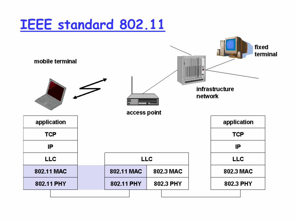
802.11 LAN architecture
wireless host communicates with base station
base station = access point (AP)
Basic Service Set (BSS)(aka “cell”) in infrastructure mode contains:
wireless hosts
access point (AP): base station
ad hoc mode: hosts only
BSS 1
BSS 2
Internet
hub, switchor router
AP
AP
IEEE standard 802.11

802.11: Channels, association
802.11b: 2.4GHz-2.485GHz spectrum divided into 11 channels at different frequencies AP admin chooses frequency for AP interference possible: channel can be same as
that chosen by neighboring AP!
host: must associate with an AP scans channels, listening for beacon frames
containing AP’s name (SSID) and MAC address selects AP to associate with may perform authentication will typically run DHCP to get IP address in AP’s
subnet

802.11: passive/active scanning
AP 2AP 1
H1
BBS 2BBS 1
122
34
Active Scanning:
(1) Probe Request frame broadcast from H1
(2) Probes response frame sent from APs
(3) Association Request frame sent: H1 to selected AP
(4) Association Response frame sent: selected AP to H1
AP 2AP 1
H1
BBS 2BBS 1
1
23
1
Passive Scanning:(1) beacon frames sent from APs(2) association Request frame sent:
H1 to selected AP (3) association Response frame sent:
selected AP to H1
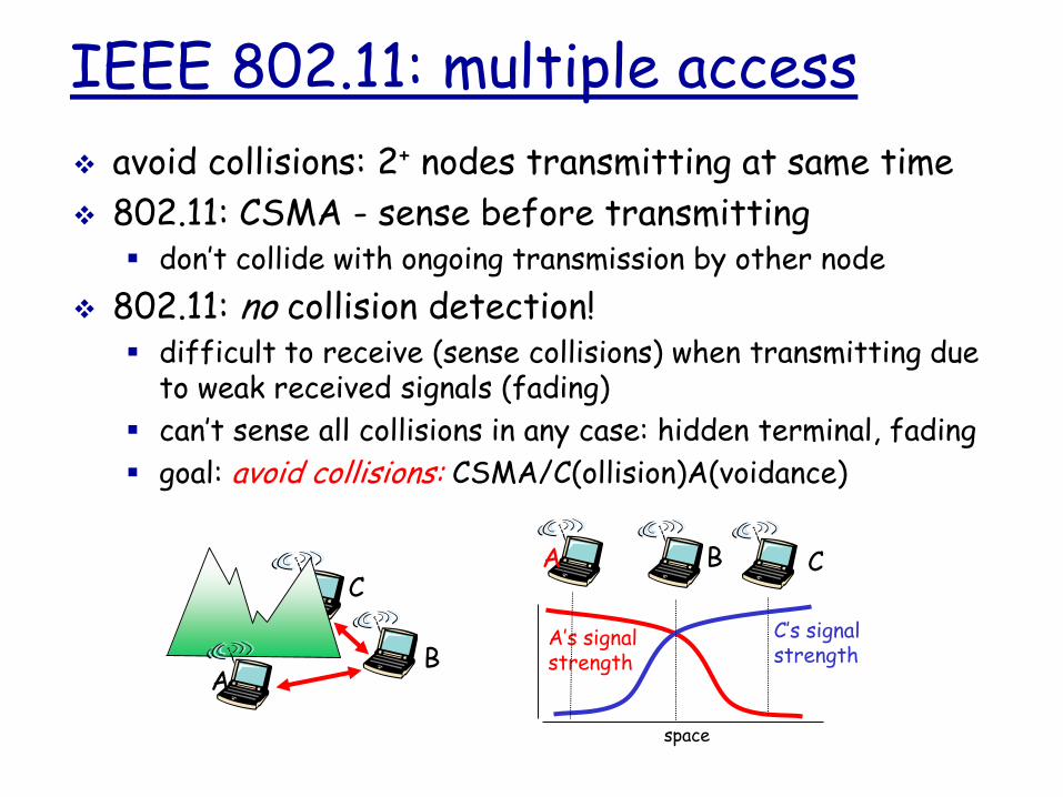
IEEE 802.11: multiple access
avoid collisions: 2+ nodes transmitting at same time
802.11: CSMA - sense before transmitting don’t collide with ongoing transmission by other node
802.11: no collision detection! difficult to receive (sense collisions) when transmitting due
to weak received signals (fading)
can’t sense all collisions in any case: hidden terminal, fading
goal: avoid collisions: CSMA/C(ollision)A(voidance)
AB
CA B C
A’s signalstrength
space
C’s signalstrength

IEEE 802.11 MAC Protocol: CSMA/CA
802.11 sender
1 if sense channel idle for DIFS then
transmit entire frame (no CD)
2 if sense channel busy then
start random backoff time
timer counts down while channel idle
transmit when timer expires
if no ACK, increase random backoff interval, repeat 2
802.11 receiver
- if frame received OK
return ACK after SIFS (ACK needed due to hidden terminal problem)
sender receiver
DIFS
data
SIFS
ACK
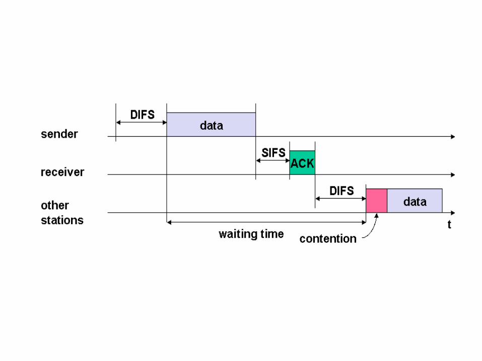

802.11 - competing stations - simple version
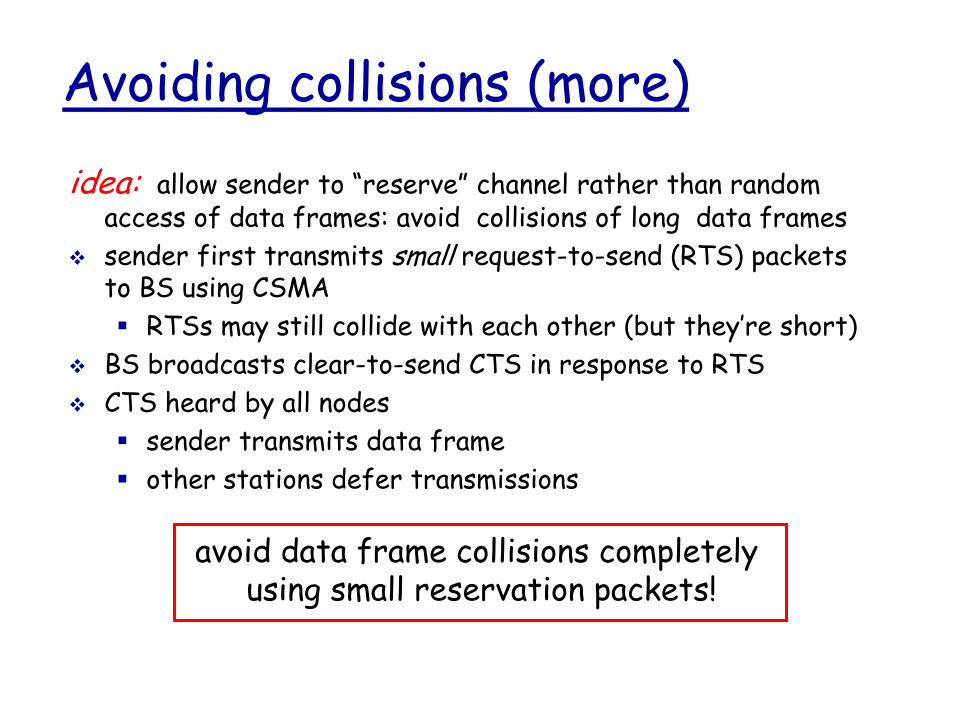
Avoiding collisions (more)
idea: allow sender to “reserve” channel rather than random access of data frames: avoid collisions of long data frames
sender first transmits small request-to-send (RTS) packets to BS using CSMA
RTSs may still collide with each other (but they’re short)
BS broadcasts clear-to-send CTS in response to RTS
CTS heard by all nodes
sender transmits data frame
other stations defer transmissions
avoid data frame collisions completely using small reservation packets!
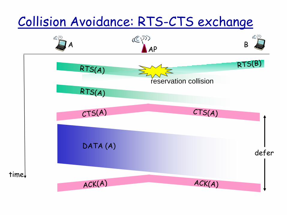
Collision Avoidance: RTS-CTS exchange
APA B
time
DATA (A)
reservation collision
defer

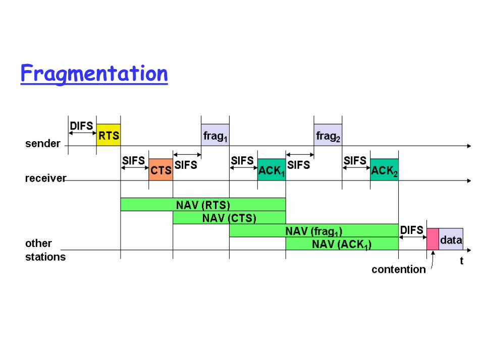
Fragmentation
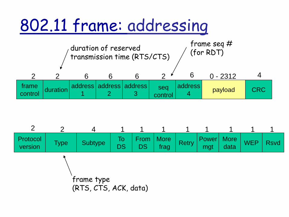
frame
controlduration
address
1
address
2
address
4
address
3payload CRC
2 2 6 6 6 2 6 0 - 2312 4
seq
control
TypeFrom
DSSubtype
To
DS
More
fragWEP
More
data
Power
mgtRetry Rsvd
Protocol
version
2 2 4 1 1 1 1 1 11 1
802.11 frame: addressingduration of reserved transmission time (RTS/CTS)
frame seq #(for RDT)
frame type(RTS, CTS, ACK, data)

MAC address format

Internetrouter
AP
H1 R1
AP MAC addr H1 MAC addr R1 MAC addr
address 1 address 2 address 3
802.11 frame
R1 MAC addr H1 MAC addr
dest. address source address
802.3 frame
802.11 frame: addressing

hub or switch
AP 2
AP 1
H1 BSS 2
BSS 1
802.11: mobility within same subnet
router H1 remains in same IP
subnet: IP address can remain same
switch: which AP is associated with H1? self-learning :
switch will see frame from H1 and “remember” which switch port can be used to reach H1

802.11: advanced capabilities
Rate Adaptation
base station, mobile dynamically change transmission rate (physical layer modulation technique) as mobile moves, SNR varies
QAM256 (8 Mbps)
QAM16 (4 Mbps)
BPSK (1 Mbps)
10 20 30 40SNR(dB)
BE
R
10-1
10-2
10-3
10-5
10-6
10-7
10-4
operating point
1. SNR decreases, BER increase as node moves away from base station
2. When BER becomes too high, switch to lower transmission rate but with lower BER
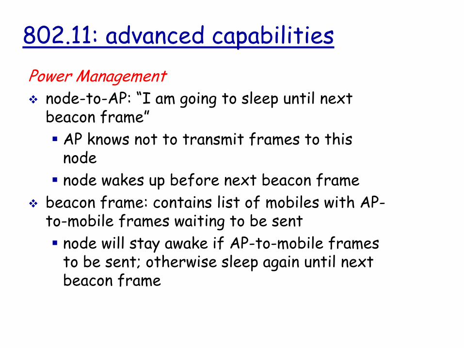
802.11: advanced capabilities
Power Management
node-to-AP: “I am going to sleep until next beacon frame”
AP knows not to transmit frames to this node
node wakes up before next beacon frame
beacon frame: contains list of mobiles with AP-to-mobile frames waiting to be sent
node will stay awake if AP-to-mobile frames to be sent; otherwise sleep again until next beacon frame
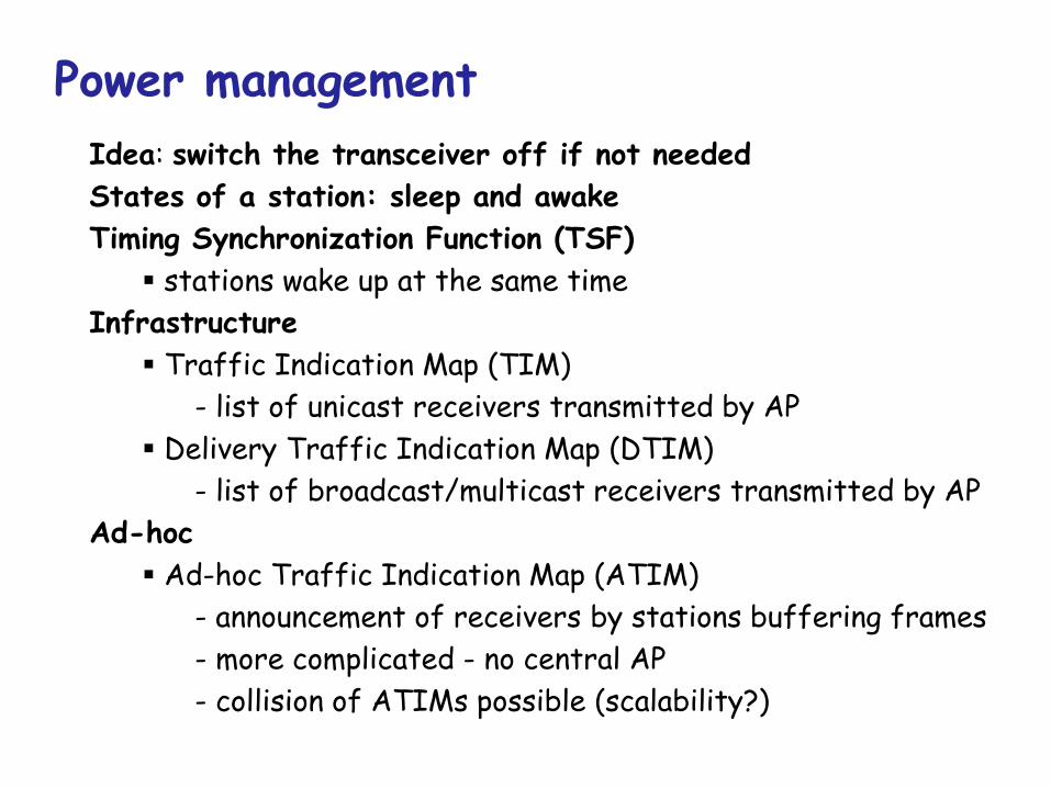
Power management
Idea: switch the transceiver off if not needed
States of a station: sleep and awake
Timing Synchronization Function (TSF)
stations wake up at the same time
Infrastructure
Traffic Indication Map (TIM)
- list of unicast receivers transmitted by AP
Delivery Traffic Indication Map (DTIM)
- list of broadcast/multicast receivers transmitted by AP
Ad-hoc
Ad-hoc Traffic Indication Map (ATIM)
- announcement of receivers by stations buffering frames
- more complicated - no central AP
- collision of ATIMs possible (scalability?)

Power saving with wake-up patterns (infrastructure)
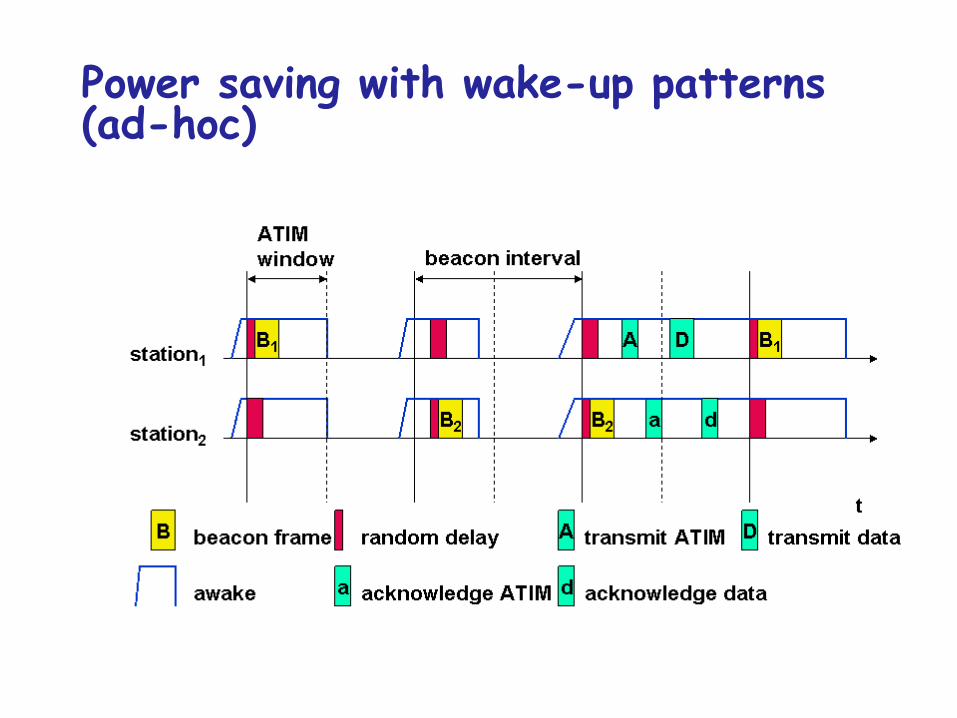
Power saving with wake-up patterns (ad-hoc)
Mradius of
coverage
S
SS
P
P
P
P
M
S
Master device
Slave device
Parked device (inactive)P
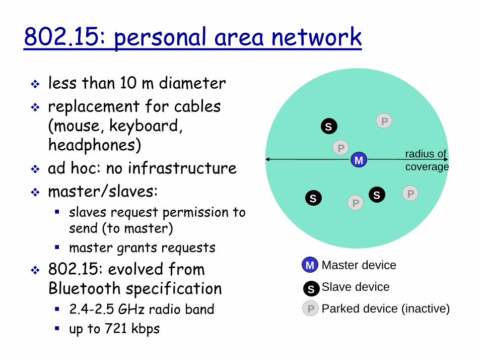
802.15: personal area network
less than 10 m diameter
replacement for cables (mouse, keyboard, headphones)
ad hoc: no infrastructure
master/slaves: slaves request permission to
send (to master)
master grants requests
802.15: evolved from Bluetooth specification 2.4-2.5 GHz radio band
up to 721 kbps

802.16: WiMAX
like 802.11 & cellular: base station model transmissions to/from base
station by hosts with omnidirectional antenna
base station-to-base station backhaul with point-to-point antenna
unlike 802.11: range ~ 6 miles (“city
rather than coffee shop”)
~14 Mbps
point-to-multipoint
point-to-point

802.16: WiMAX: downlink, uplink scheduling
transmission frame
down-link subframe: base station to node
uplink subframe: node to base station
pre
am
.
DL-
MAPUL-
MAP
DL
burst 1SS #1
DL
burst 2
DL
burst n
Initial
maint.
request
conn.
downlink subframe
SS #2 SS #k
uplink subframe
…
…
…
…
base station tells nodes who will get to receive (DL map) and who will get to send (UL map), and when
WiMAX standard provide mechanism for scheduling, but not scheduling algorithm

Mobile
Switching
Center
Public telephonenetwork, andInternet
Mobile
Switching
Center
Components of cellular network architecture
connects cells to wide area net manages call setup (more later!) handles mobility (more later!)
MSC
covers geographical region base station (BS) analogous to 802.11 AP mobile users attach to network through BS air-interface:physical and link layer protocol between mobile and BS
cell
wired network
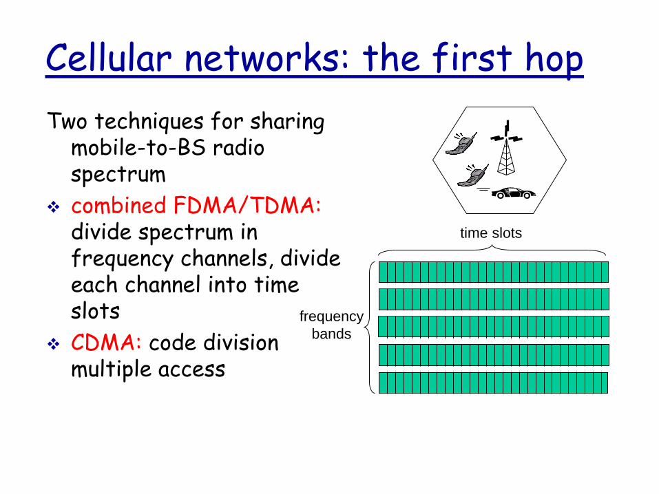
Cellular networks: the first hop
Two techniques for sharing mobile-to-BS radio spectrum
combined FDMA/TDMA:divide spectrum in frequency channels, divide each channel into time slots
CDMA: code division multiple access
frequency
bands
time slots

Cellular standards: brief survey
2G systems: voice channels IS-136 TDMA: combined FDMA/TDMA (North
America)
GSM (global system for mobile communications): combined FDMA/TDMA most widely deployed
IS-95 CDMA: code division multiple access
GSMDon’t drown in a bowl
of alphabet soup: use this
for reference only

Cellular standards: brief survey
2.5 G systems: voice and data channels for those who can’t wait for 3G service: 2G extensions
general packet radio service (GPRS) evolved from GSM
data sent on multiple channels (if available)
enhanced data rates for global evolution (EDGE) also evolved from GSM, using enhanced modulation
data rates up to 384K
CDMA-2000 (phase 1) data rates up to 144K
evolved from IS-95
Cellular standards: brief survey
3G systems: voice/data Universal Mobile Telecommunications Service (UMTS) data service: High Speed Uplink/Downlink packet
Access (HSDPA/HSUPA) CDMA-2000: CDMA in TDMA slots
data service: 1xEvolution Data Optimized (1xEVDO)up to 14 Mbps

BSCBTS
Base transceiver station (BTS)
Base station controller (BSC)
Mobile Switching Center (MSC)
Mobile subscribers
Base station system (BSS)
Legend
2G (voice) network architecture
MSC
Public telephonenetwork
GatewayMSC
G
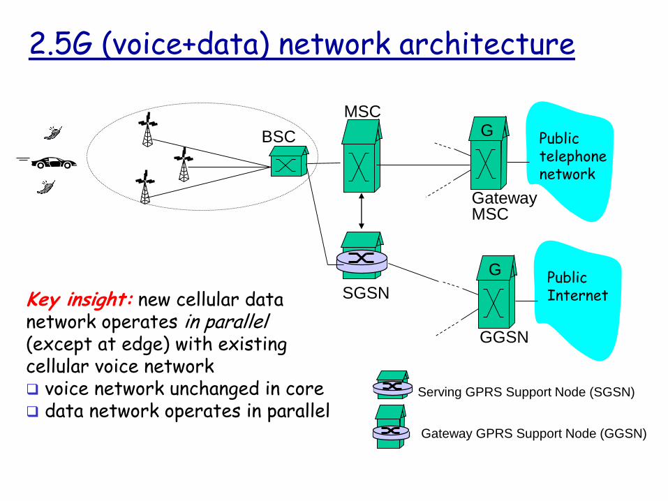
2.5G (voice+data) network architecture
BSC
MSC
SGSN
Public telephonenetwork
GatewayMSC
G
Serving GPRS Support Node (SGSN)
Gateway GPRS Support Node (GGSN)
Public Internet
GGSN
G
Key insight: new cellular datanetwork operates in parallel(except at edge) with existing cellular voice network voice network unchanged in core data network operates in parallel
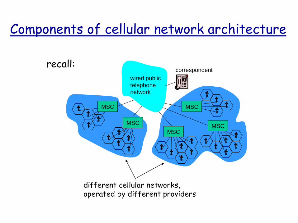
Components of cellular network architecture
correspondent
MSC
MSC
MSCMSC
MSC
wired public
telephone
network
different cellular networks,operated by different providers
recall:

Handling mobility in cellular networks
home network: network of cellular provider you subscribe to (e.g., Sprint PCS, Verizon) home location register (HLR): database in home
network containing permanent cell phone #, profile information (services, preferences, billing), information about current location (could be in another network)
visited network: network in which mobile currently resides visitor location register (VLR): database with
entry for each user currently in network could be home network

Public
switched
telephone
network
mobile
user
home
Mobile
Switching
Center
HLRhome
network
visited
network
correspondent
Mobile
Switching
Center
VLR
GSM: indirect routing to mobile
1 call routed
to home network
2
home MSC consults HLR,
gets roaming number of
mobile in visited network
3
home MSC sets up 2nd leg of call
to MSC in visited network
4
MSC in visited network completes
call through base station to mobile
Mobile
Switching
Center
VLR
old BSSnew BSS
old
routing
new
routing
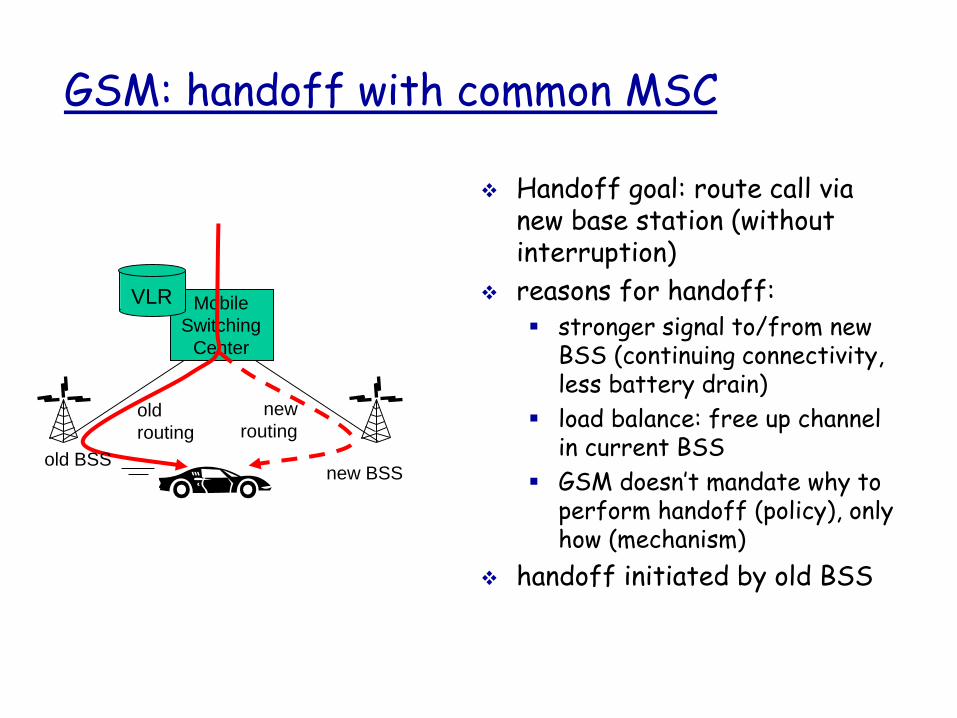
GSM: handoff with common MSC
Handoff goal: route call via new base station (without interruption)
reasons for handoff: stronger signal to/from new
BSS (continuing connectivity, less battery drain)
load balance: free up channel in current BSS
GSM doesn’t mandate why to perform handoff (policy), only how (mechanism)
handoff initiated by old BSS
Mobile
Switching
Center
VLR
old BSS
1
3
24
5 6
78
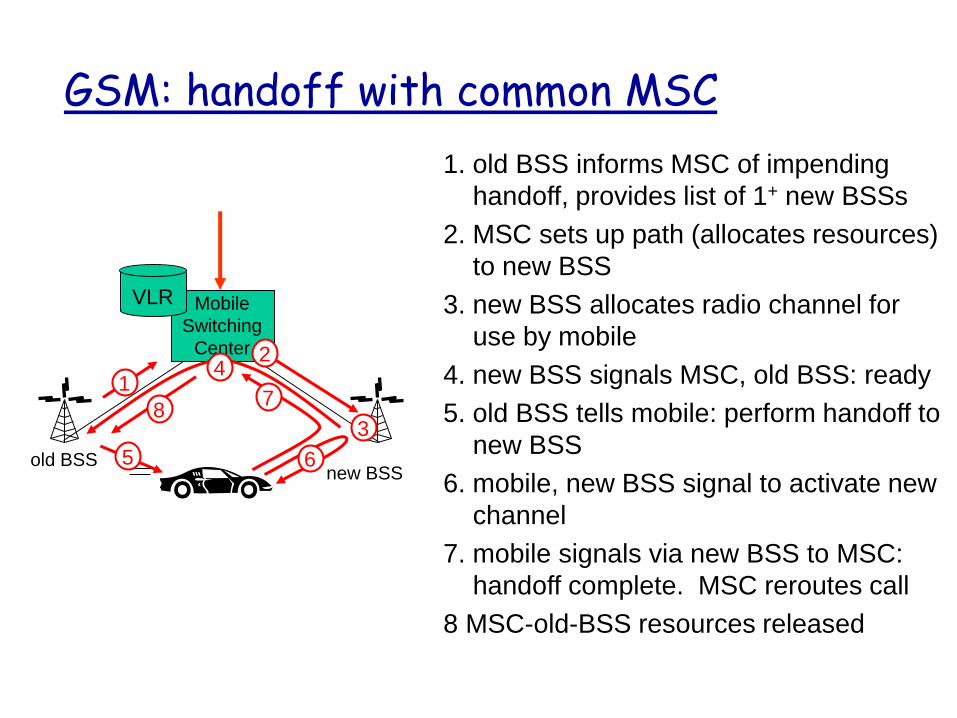
GSM: handoff with common MSC
new BSS
1. old BSS informs MSC of impending
handoff, provides list of 1+ new BSSs
2. MSC sets up path (allocates resources)
to new BSS
3. new BSS allocates radio channel for
use by mobile
4. new BSS signals MSC, old BSS: ready
5. old BSS tells mobile: perform handoff to
new BSS
6. mobile, new BSS signal to activate new
channel
7. mobile signals via new BSS to MSC:
handoff complete. MSC reroutes call
8 MSC-old-BSS resources released
home network
Home
MSC
PSTN
correspondent
MSC
anchor MSC
MSCMSC
(a) before handoff
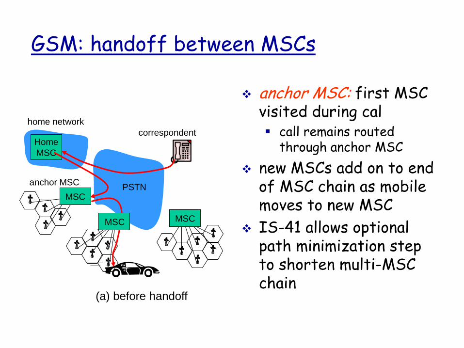
GSM: handoff between MSCs
anchor MSC: first MSC visited during cal call remains routed
through anchor MSC
new MSCs add on to end of MSC chain as mobile moves to new MSC
IS-41 allows optional path minimization step to shorten multi-MSC chain
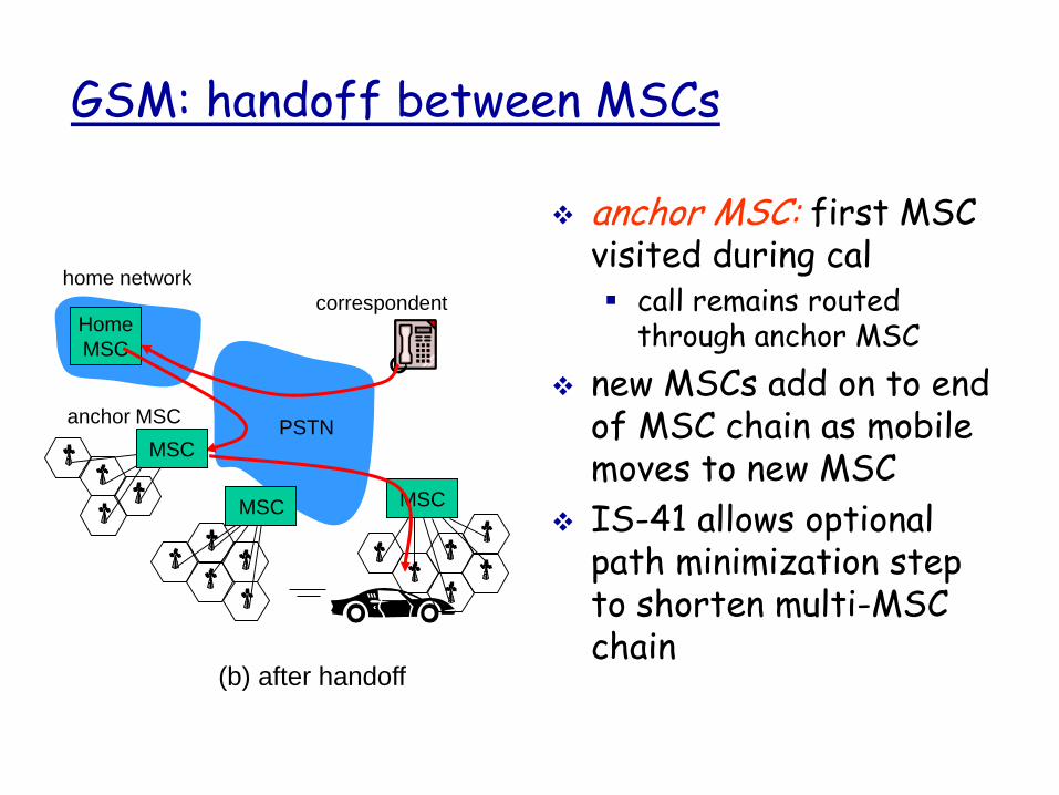
home network
Home
MSC
PSTN
correspondent
MSC
anchor MSC
MSCMSC
(b) after handoff
GSM: handoff between MSCs
anchor MSC: first MSC visited during cal call remains routed
through anchor MSC
new MSCs add on to end of MSC chain as mobile moves to new MSC
IS-41 allows optional path minimization step to shorten multi-MSC chain