wireless communication fundamentals - ranger.uta.eduranger.uta.edu/~li/2-8-lecture.pdf · by t. s....
TRANSCRIPT
1
Wireless Communication Fundamentals
Feb. 8, 2005
Dr. Chengzhi Li

2
Suggested Reading• Chapter 2 “Wireless Communications”
by T. S. Rappaport, 2001 (version 2)
• “Rayleigh Fading Channels in Mobile Digital Communication Systems Part I: Characterization”, IEEE Communications Magazine, 1997
3
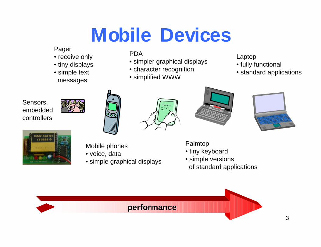
Mobile Devices
performanceperformance
Pager• receive only• tiny displays• simple text
messages
Mobile phones• voice, data• simple graphical displays
PDA• simpler graphical displays• character recognition• simplified WWW
Palmtop• tiny keyboard• simple versions
of standard applications
Laptop• fully functional• standard applications
Sensors,embeddedcontrollers
4
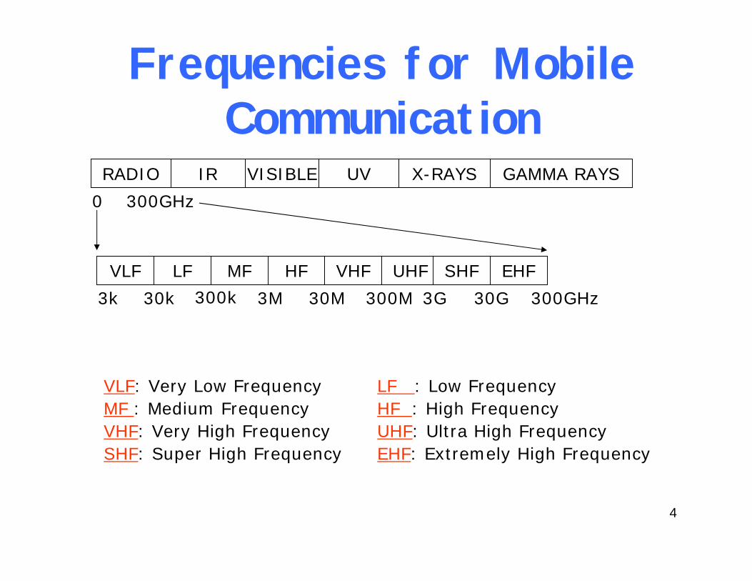
RADIO IR VISIBLE UV X-RAYS GAMMA RAYS
0 300GHz
VLF LF MF HF VHF UHF SHF EHF
3k 30k 300k 3M 30M 300M 3G 30G 300GHz
VLF: Very Low Frequency LF : Low FrequencyMF : Medium Frequency HF : High FrequencyVHF: Very High Frequency UHF: Ultra High FrequencySHF: Super High Frequency EHF: Extremely High Frequency
Frequencies for Mobile Communication
5
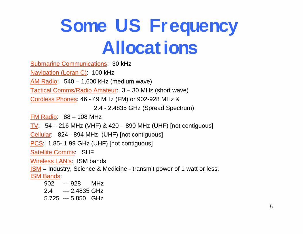
Submarine Communications: 30 kHzNavigation (Loran C): 100 kHzAM Radio: 540 – 1,600 kHz (medium wave)Tactical Comms/Radio Amateur: 3 – 30 MHz (short wave)Cordless Phones: 46 - 49 MHz (FM) or 902-928 MHz &
2.4 - 2.4835 GHz (Spread Spectrum)FM Radio: 88 – 108 MHz TV: 54 – 216 MHz (VHF) & 420 – 890 MHz (UHF) [not contiguous]Cellular: 824 - 894 MHz (UHF) [not contiguous]PCS: 1.85- 1.99 GHz (UHF) [not contiguous]Satellite Comms: SHFWireless LAN’s: ISM bandsISM = Industry, Science & Medicine - transmit power of 1 watt or less.ISM Bands:
902 --- 928 MHz2.4 --- 2.4835 GHz5.725 --- 5.850 GHz
Some US Frequency Allocations

6
Time-Domain View of Signals• A generic sine wave
– Amplitude A: Peak value of a signal at any time.
– Frequency f: Inverse of the period (f = 1/T) represents number of cycles per second (measured in Hertz (Hz)) i.e., this is the rate at which the signal repeats.
– Phase φ: Relative position within a signal period.

7
Frequency and Amplitude• Measure of frequency• 1 Hertz = 1 cycle/sec
– Unit of bandwidth for analog device– Frequency of sine wave in diagram: 4Hz
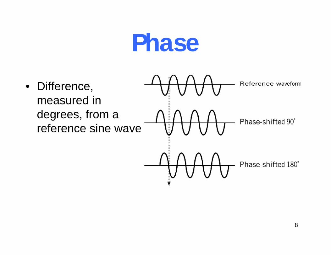
8
Phase• Difference,
measured in degrees, from a reference sine wave

9
Signal Propagation Ranges
distance
sender
transmission
detection
interference
• Transmission range– communication possible– low error rate
• Detection range– detection of the signal
possible– no communication
possible
• Interference range– signal may not be
detected – signal adds to the
background noise

10
Propagation Mechanisms• Reflection: propagation wave reflected by object
larger than wavelength• Diffraction: wave obstructed by surface with
sharp, irregular edges• Scattering: wave hits loose objects smaller than
wavelength; signal scattered in bunch of outgoing weaker signals
reflection scatteringdiffraction
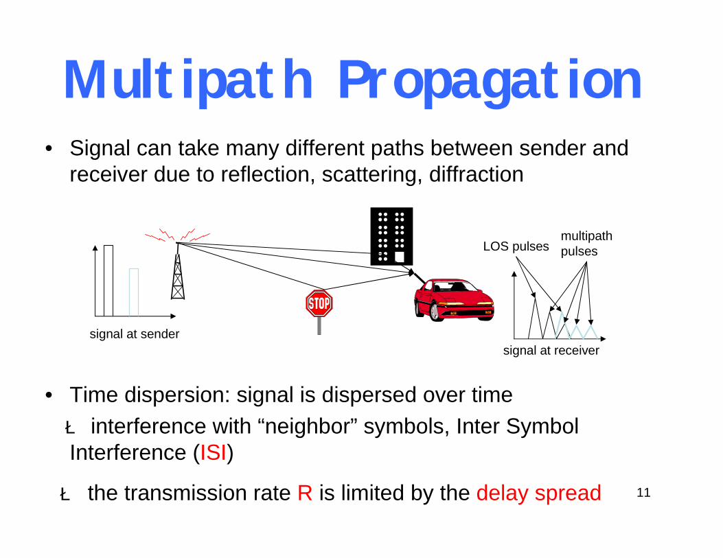
11
• Signal can take many different paths between sender and receiver due to reflection, scattering, diffraction
• Time dispersion: signal is dispersed over timeè interference with “neighbor” symbols, Inter Symbol Interference (ISI)
è the transmission rate R is limited by the delay spread
Multipath Propagation
signal at sendersignal at receiver
LOS pulsesmultipathpulses

12
Propagation Models• Large scale propagation
model– Predict the mean signal
strength over the distance between transmitter and receiver (path loss)
• Small scale propagation model– Characterize the
fluctuations of signal strength over very short travel distances or very short time period (multipath fading)

13
Large Scale Propagation Models
• Propagation in free space:
– Friis free space equation:
• Propagation along the earth’s surface: – 2-ray model
rttr ggd
PP2
4
=
πλ Pt = transmit power
gt, gr = transmit/receive antenna gainsd = distance between the antennas
rtrt
tr ggdhhPP
2
2
=
ht, hr = transmit/receive antenna height
LOS Path
Ground Reflection
hrd
ht

14
Path Loss• Path Loss (PL)
– PL = Pt/Pr
– PLdB = 10*log(PL) = 10*log(Pt /Pr)
• Path Loss Model
• Log-normal Shadowing Model
)log(10 )()(
)( )(
00
0
ddndPLdPL
dddPL
dBdB
n
+=
∝n :path loss exponentd0 :close-in reference
distanceXσ :zero mean Gausian
random variable
σXddndPLdPL dBdB ++= )log(10 )()(
00
4 to 6Obstructed in building
1.6 to 1.8In building line-of-sight
2.7 to 3.5Urban area
2Free space
Path loss exponents
1/(2πσ)0.5 exp[ {-x2/2σ2}]

15
Example for Path Loss

16
Doppler Effect• Caused by
– the speed of mobile – speed of surrounding objects
• If the surrounding objects move at a greater speed than the mobile, this effect dominates, otherwise it can be ignored
• Doppler shift– Mobile moving towards the transmitter with speed v: a maximum
positive Doppler shift
– The n-th path, moving within an angle αn , has a Doppler shift of
– If mobile moves away from transmitter, the frequency of received signal will be fr = fc - fd
– If mobile moves towards transmitter, the frequency of received signal will be fr = fc + fd
λvfd =max ( )nd
vf αλ
cos=
v
αn
n-th path

17
Classification of Small Scale Fading
Small Scale Fading (Based on multipath delay spread)
Small Scale Fading (Based on Doppler spread)
Flat Fading
Delay Spread < Symbol period
Frequency Selective Fading
Delay Spread > Symbol period
Fast Fading
1/Doppler Shift < Symbol period
Slow Fading
1/Doppler Shift > Symbol period
Freq. sel.Fast
Freq. sel.slow
FlatFast
FlatSlow
18
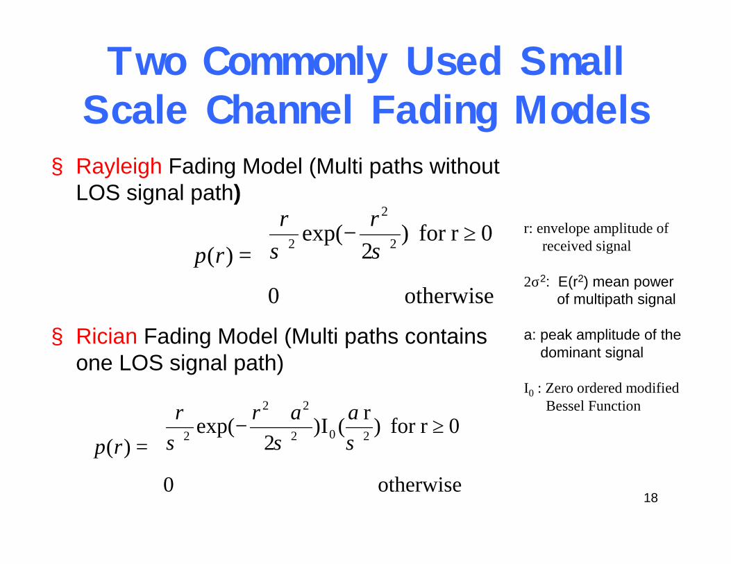
Two Commonly Used Small Scale Channel Fading Models
§ Rayleigh Fading Model (Multi paths without LOS signal path)
§ Rician Fading Model (Multi paths contains one LOS signal path)
≥−
=
otherwise 0
0r for )2
exp()( 2
2
2 σσrr
rpr: envelope amplitude of
received signal
2σ2: E(r2) mean power of multipath signal
a: peak amplitude of the dominant signal
I0 : Zero ordered modifiedBessel Function
≥Ι
+−
=
otherwise 0
0r for )r ()2
exp()( 202
22
2 σσσaarr
rp

19
Digital Modulation• Modern wireless systems use digital
modulation• Three types of digital modulation
– Amplitude shift keying (ASK)
– Frequency shift keying (FSK)
– Phase shift keying (PSK)

20
Modulation Examples• M-ary Phase Shift Keying (MPSK)
– Phase modulation
– bits encoded into one symbol
– Examples• BPSK:
• QPSK:
• M-ary Quadrature Amplitude Modulation (M-QAM)– Combining phase modulation and amplitude modulation
M,1,2, i T,t0 ), t f (2 cosA (t)Si =≤≤+π= iθM2log
πθθ == 21 ,0
2/3 , ,2/ ,0 4321 πθπθπθθ ====
M,1,2, i T,t0 ), t f (2 cos A(t)S ii =≤≤+π= iθ

21
Examples for M-QAM
==
)2cos()2sin(
2
1
ftft
πϕπϕ
bases functions