wireless controls in action tarang p™ - fcc id · report. tarang p user manual page 5 of 17 2....
TRANSCRIPT
TaPro
Mel
#4/
Kum
Ban
P: +
info
WiM
araodu
lange Sys
/1, 7th Cr
mara Par
ngalore 5
+91 80 2
o@melan
ireless controMelange S
ngct M
stems Pr
ross,
rk West,
560 020
23561023
ngesystem
ols in actionSystems P
g P™Manu
rivate Lim
3, 23462
ms.com
n Private L
™ ual
mited,
2175
Limited
Tarang P User Manual Page 2 of 17
Table of Contents
1. Tarang-P20 FCC Compliance ------------------------------------------------------------------------------------------- 3
2. Tarang-P series -------------------------------------------------------------------------------------------------------------- 5
2.1 Features --------------------------------------------------------------------------------------------------------------------- 5
3. Tarang P20 -------------------------------------------------------------------------------------------------------------------- 6
3.1 Specifications --------------------------------------------------------------------------------------------------------------- 6 3.2 Mechanical Drawings ----------------------------------------------------------------------------------------------------- 7
4. Interface ----------------------------------------------------------------------------------------------------------------------- 8
4.1 Interfacing with microcontroller --------------------------------------------------------------------------------------- 9
5. Table of AT Commands ------------------------------------------------------------------------------------------------- 10
5.1 Table of General AT Commands ------------------------------------------------------------------------------------- 10
6. Updating Firmware ------------------------------------------------------------------------------------------------------- 11
6.1 Software erase of code ------------------------------------------------------------------------------------------------ 11
6.2 To Hardware Erase of the module ---------------------------------------------------------------------------------- 11
6.3 Steps to load the firmware -------------------------------------------------------------------------------------------- 12
7. Placement Guidelines --------------------------------------------------------------------------------------------------- 16
8. Contact Details ------------------------------------------------------------------------------------------------------------- 17
Tarang P User Manual Page 3 of 17
1. Tarang-P20 FCC Compliance
This device complies with Part 15 of the FCC rules. Operation is subject to following two conditions:
1. This device may not cause harmful interference and 2. This device must accept any interference received including interference that may cause undesired operation of this device.
The changes or modifications not expressly approved by the party responsible for Compliance could void
the user’s authority to operate the equipment.
To comply with the FCC RF exposure compliance requirements, this device and its antenna must not be
co-located or operating to conjunction with any other antenna or transmitter, except if installed in
compliance with FCC Multi Transmitter procedures.
To inherit the modular approval, the antennas for this transmitter must be installed to provide a
separation distance of 20cm from all persons and must not be co-located or operating in conjunction with
any other antenna or transmitter.
To OEM Installer:
1. The Original Equipment Manufacturer (OEM) must ensure that FCC labeling requirements are met. This
includes a clearly visible label on the outside of the OEM enclosure specifying "Contains FCC ID: N3Y-
TARANG-P20” or “Contains transmitter Module FCC ID: N3Y-TARANG-P20”.
2. In the user manual, final system integrator must ensure that there is no instruction provided to install
or remove the transmitter module.
3. Transmitter module must be installed and used in strict accordance with the Manufacturer’s
instructions as described in the user documentation that comes with the product.
The user manual of the final host system must contain the following statements:
This device complies with Part 15 of the FCC rules. Operation is subject to following two conditions:
1. This device may not cause harmful interference and

Tarang P User Manual Page 4 of 17
2. This device must accept any interference received including interference that may cause undesired
operation of this device.
The changes or modifications not expressly approved by the party responsible for compliance could void
the user’s authority to operate the equipment.
To comply with the FCC RF exposure compliance requirements, this device and its antenna must not be
co-located or operating to conjunction with any other antenna or transmitter, except if installed in
compliance with FCC Multi Transmitter procedures.
To inherit the modular approval, the antennas for this transmitter must be installed to provide a
separation distance of at least 20cm from all persons and must not be co-located or operating in
conjunction with any other antenna or transmitter.
Note:
The buyer of the module who will incorporate this module into his host must submit the final product to
the manufacturer of the module and the MANUFACTURER OF THE MODULE WILL VERIFY that the
product is incorporated in host equipment in a way that is represented by the testing as shown in the test
report.
Tarang P User Manual Page 5 of 17
2. Tarang-P series
Tarang-P series modules are designed with low to medium transmit power and for high reliability wireless
networks. The modules require minimal power and provide reliable delivery of data between devices. The
interfaces provided with the module help to directly fit into many industrial applications. The modules
operate within the ISM 2.4-2.4835 GHz frequency band with IEEE 802.15.4 baseband.
2.1 Features
• ZigBee® Pro Complaint platform.
• Direct Sequence Spread Spectrum.
• RF Data rate: 250 kbps.
• Acknowledgement mode communication with retries.
Tarang P User Manual Page 6 of 17
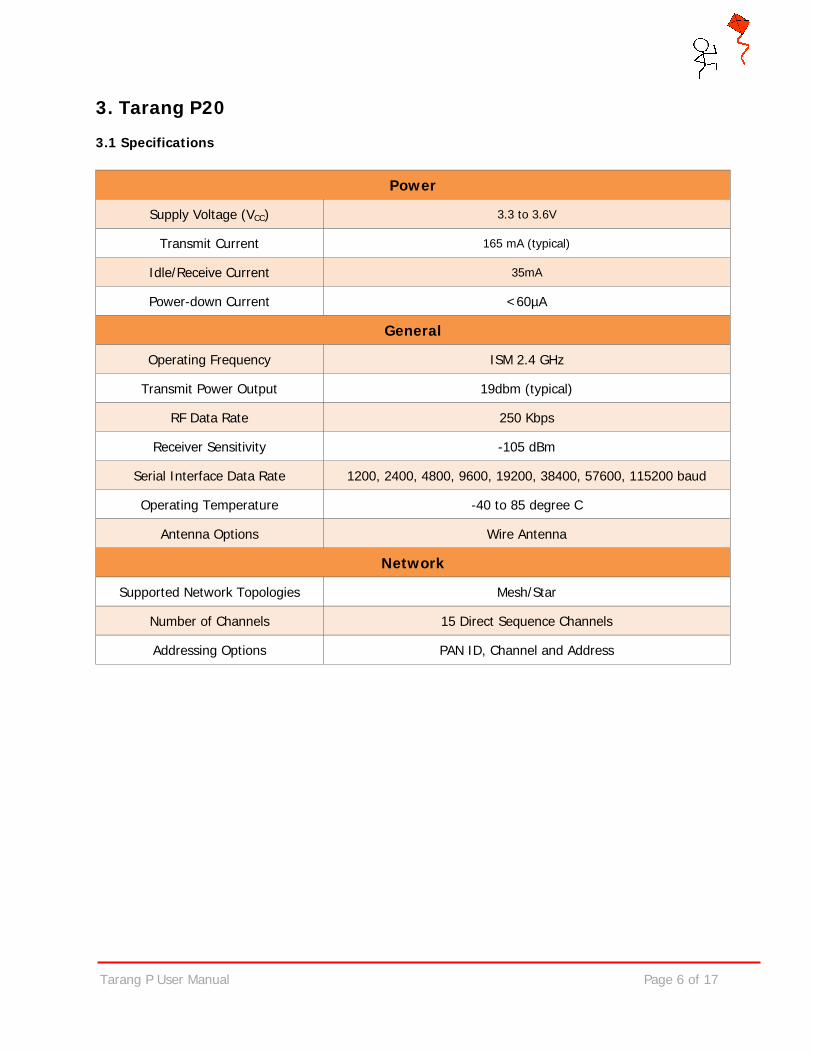
3. Tarang P20 3.1 Specifications
Power
Supply Voltage (VCC) 3.3 to 3.6V
Transmit Current 165 mA (typical)
Idle/Receive Current 35mA
Power-down Current <60µA
General
Operating Frequency ISM 2.4 GHz
Transmit Power Output 19dbm (typical)
RF Data Rate 250 Kbps
Receiver Sensitivity -105 dBm
Serial Interface Data Rate 1200, 2400, 4800, 9600, 19200, 38400, 57600, 115200 baud
Operating Temperature -40 to 85 degree C
Antenna Options Wire Antenna
Network
Supported Network Topologies Mesh/Star
Number of Channels 15 Direct Sequence Channels
Addressing Options PAN ID, Channel and Address
Tarang P User Manual Page 7 of 17
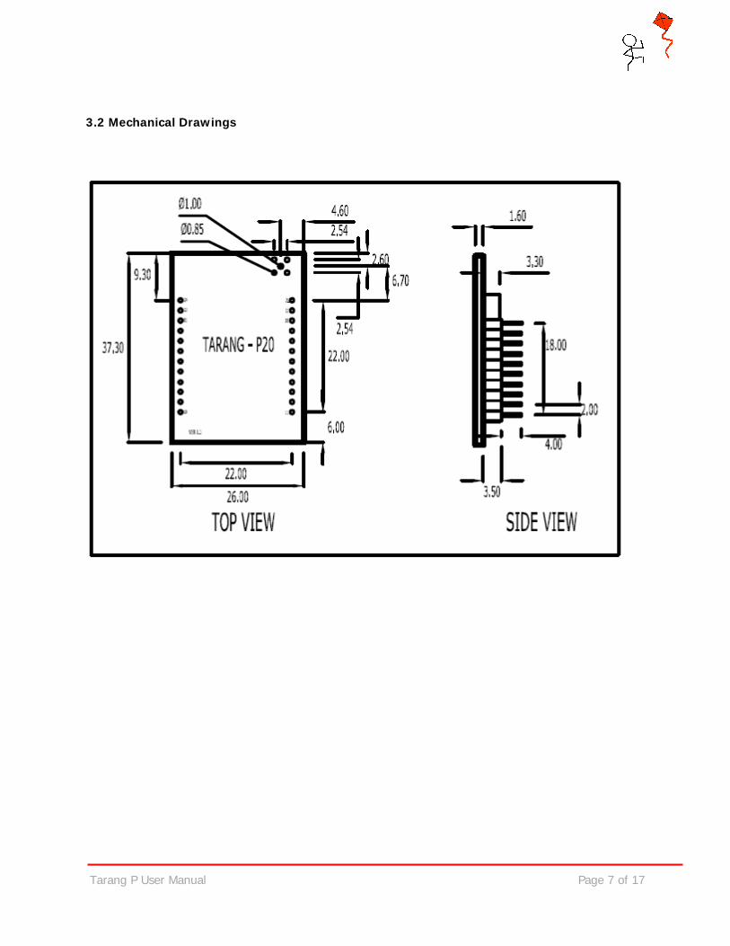
3.2 Mechanical Drawings
Tarang P User Manual Page 8 of 17
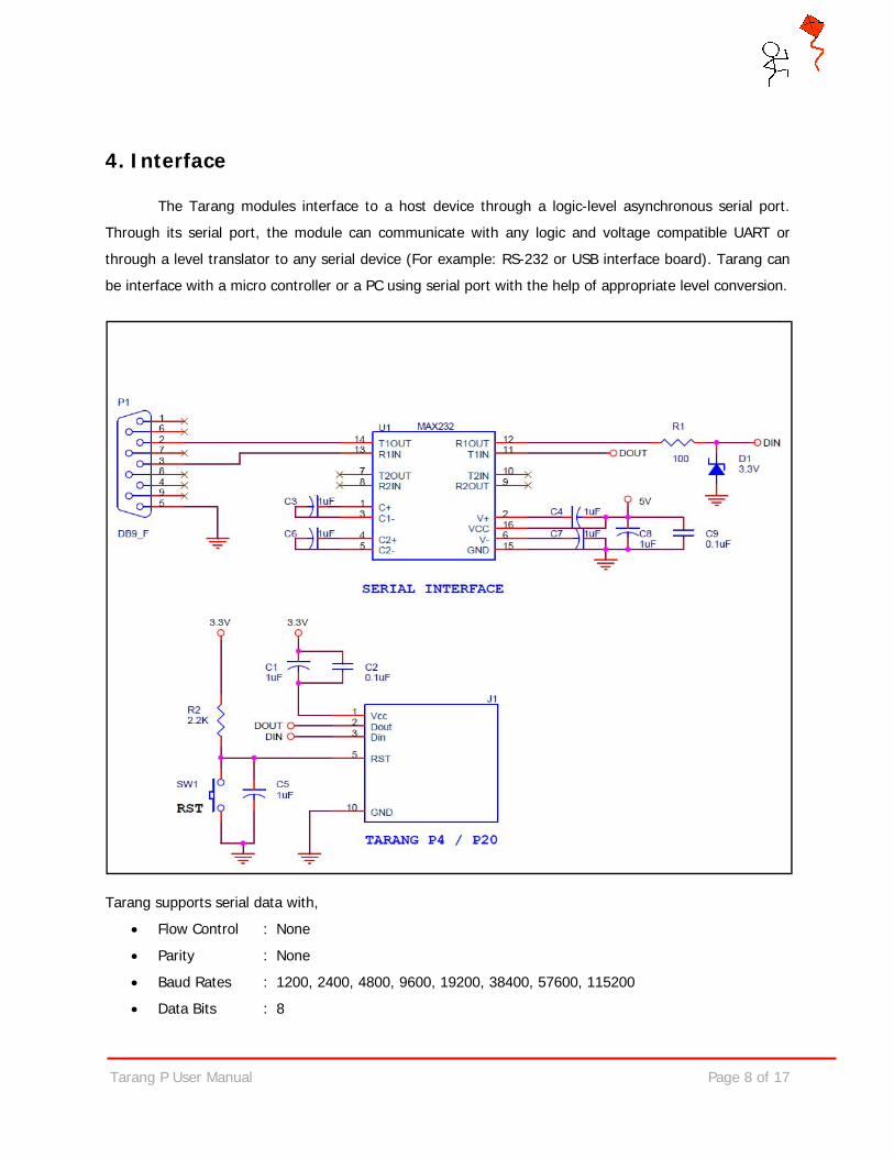
4. Interface
The Tarang modules interface to a host device through a logic-level asynchronous serial port.
Through its serial port, the module can communicate with any logic and voltage compatible UART or
through a level translator to any serial device (For example: RS-232 or USB interface board). Tarang can
be interface with a micro controller or a PC using serial port with the help of appropriate level conversion.
Tarang supports serial data with,
• Flow Control : None
• Parity : None
• Baud Rates : 1200, 2400, 4800, 9600, 19200, 38400, 57600, 115200
• Data Bits : 8
Tarang P User Manual Page 9 of 17
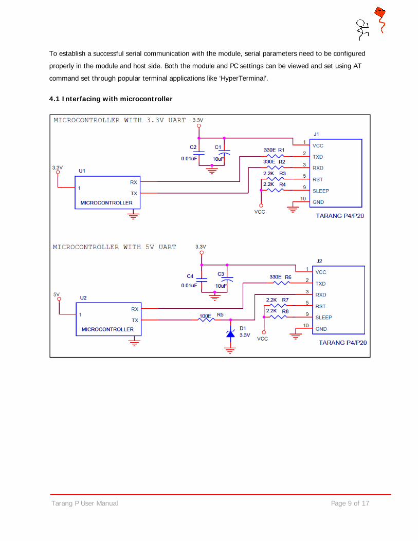
To establish a successful serial communication with the module, serial parameters need to be configured
properly in the module and host side. Both the module and PC settings can be viewed and set using AT
command set through popular terminal applications like ‘HyperTerminal’.
4.1 Interfacing with microcontroller
Tarang P User Manual Page 10 of 17
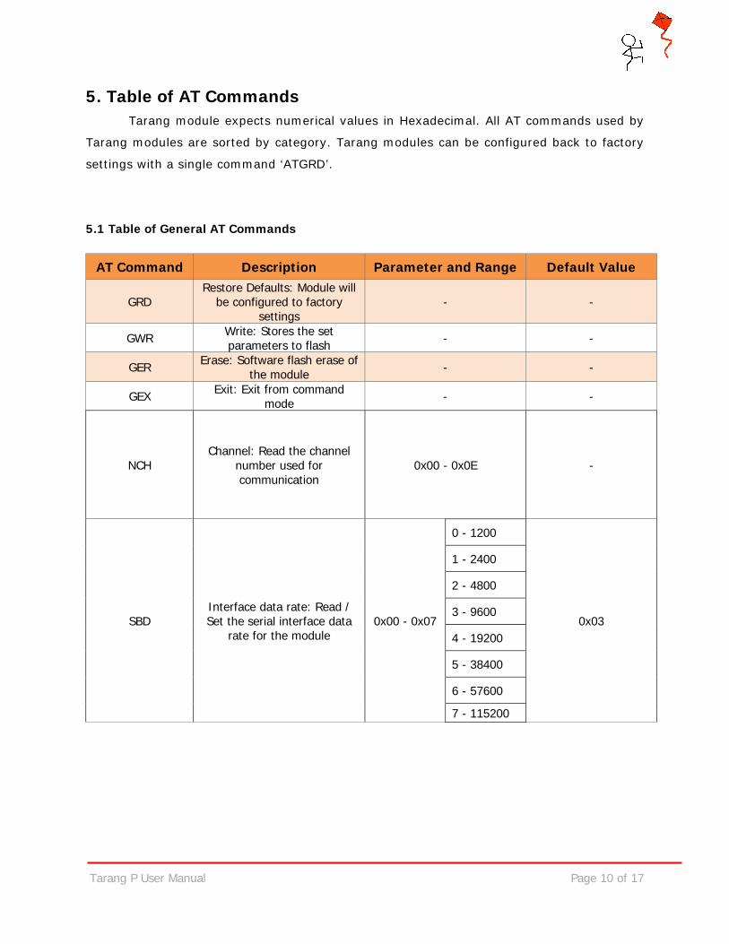
5. Table of AT Commands Tarang module expects numerical values in Hexadecimal. All AT commands used by
Tarang modules are sorted by category. Tarang modules can be configured back to factory
settings with a single command ‘ATGRD’.
5.1 Table of General AT Commands
AT Command Description Parameter and Range Default Value
GRD Restore Defaults: Module will
be configured to factory settings
- -
GWR Write: Stores the set parameters to flash - -
GER Erase: Software flash erase of the module - -
GEX Exit: Exit from command mode - -
NCH Channel: Read the channel
number used for communication
0x00 - 0x0E -
SBD Interface data rate: Read / Set the serial interface data
rate for the module 0x00 - 0x07
0 - 1200
0x03
1 - 2400
2 - 4800
3 - 9600
4 - 19200
5 - 38400
6 - 57600
7 - 115200
Tarang P User Manual Page 11 of 17
6. Updating Firmware
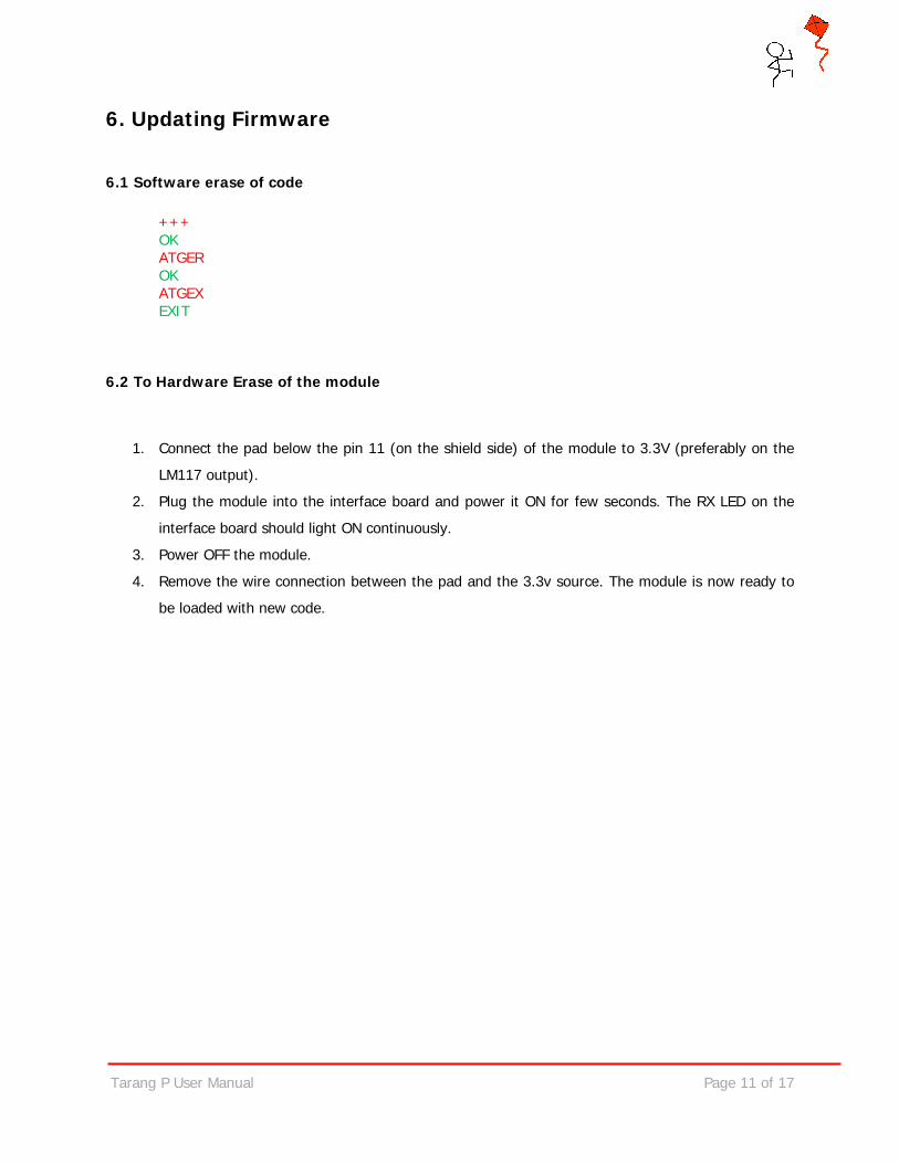
6.1 Software erase of code +++
OK ATGER OK
ATGEX EXIT
6.2 To Hardware Erase of the module
1. Connect the pad below the pin 11 (on the shield side) of the module to 3.3V (preferably on the
LM117 output).
2. Plug the module into the interface board and power it ON for few seconds. The RX LED on the
interface board should light ON continuously.
3. Power OFF the module.
4. Remove the wire connection between the pad and the 3.3v source. The module is now ready to
be loaded with new code.
Tarang P
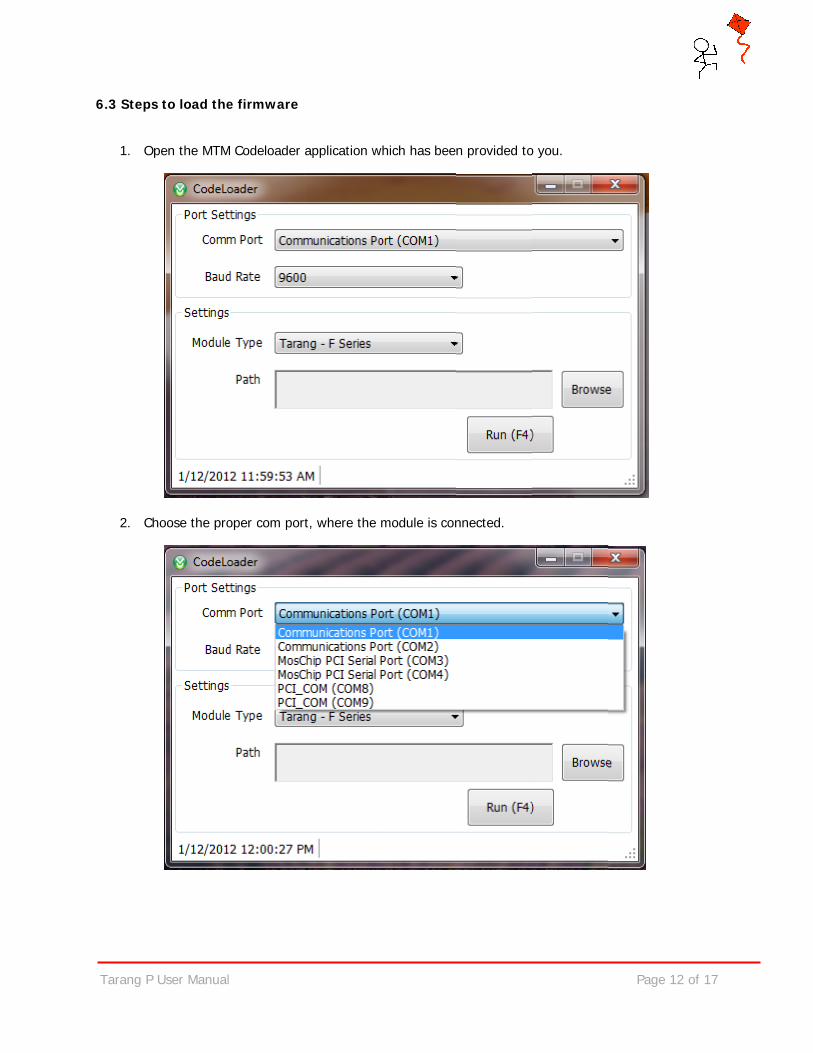
6.3 Steps
1. O
2. C
P User Manual
s to load the
Open the MTM
hoose the pro
l
e firmware
M Codeloader
oper com por
application w
rt, where the
which has bee
module is con
n provided to
nnected.
o you.
Page 12
of 17
Tarang P
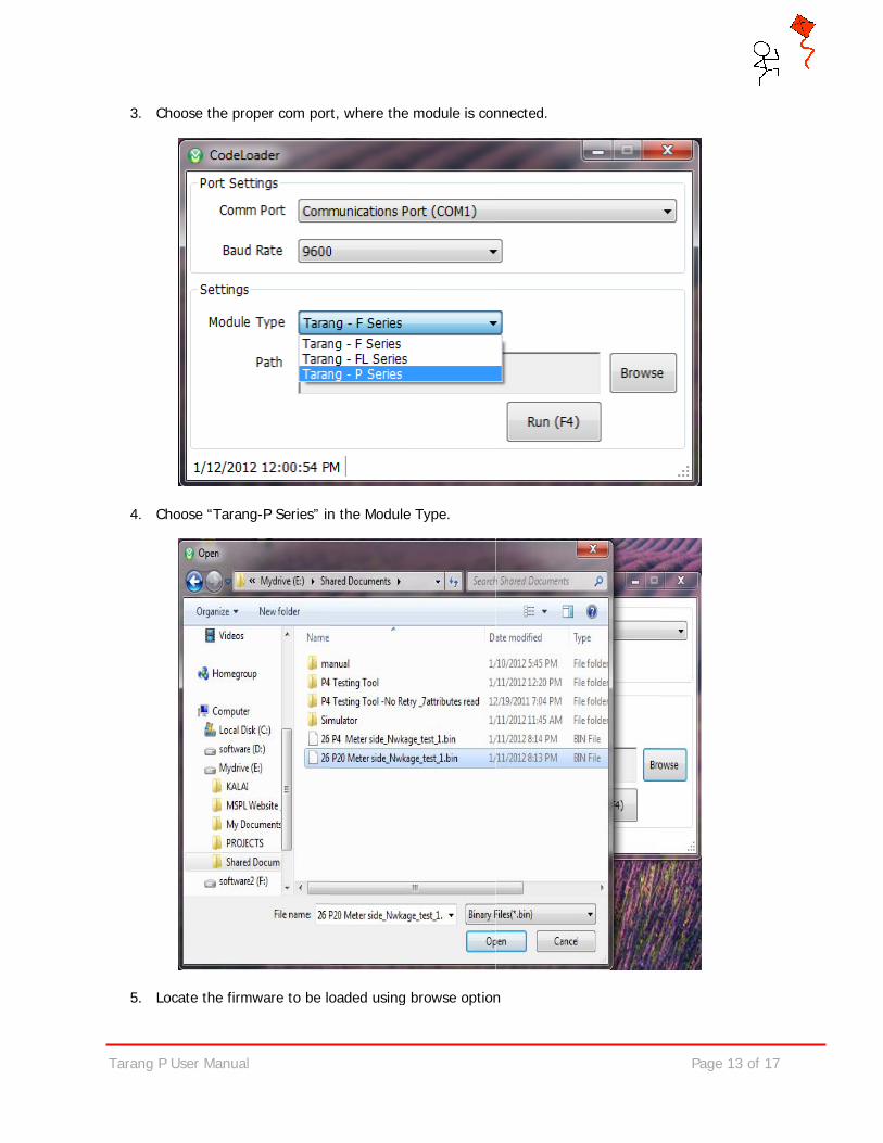
3. C
4. C
5. Lo
P User Manual
hoose the pro
hoose “Taran
ocate the firm
l
oper com por
ng-P Series” in
mware to be lo
rt, where the
n the Module
oaded using b
module is con
Type.
browse option
nnected.
n
Page 13
of 17

Tarang P
6. Pr
P User Manual
ress F4 or clic
l
ck on the Runn button, you should see a console winddow as shown
Page 14
n below.
of 17

Tarang P
After load
P User Manual
ding the windo
l
ows gets clos
ed automatically, and givee a reset to thhe module to
Page 15
start working
of 17
g.
Tarang P User Manual Page 16 of 17
7. Placement Guidelines For obtaining the best possible range, the following guidelines must be adhered to while using Tarang
modules.
1. It is important to ensure that the antennas (chip or wire) on the modules “see” open space
around them. Hence the modules must be mounted in such a way that there are no blocking obstacles
immediately next to the antennas. The modules must never be put inside a metallic enclosure unless an
external antenna is being connected to the module. The modules must not be placed too close to a wall,
table or metallic surfaces.
2. The modules must be placed as high as possible from the ground.
3. Polarization of the antennas must be the same at both sides of the link. For modules with chip
antennas, the mounting should be such that the axes of the modules are parallel to each other. For wire
antenna modules, the modules must be mounted such that the wires are parallel.
4. As far as possible, obstacles should be avoided in the communication path between the
modules. Metallic objects and concrete walls produce a lot of attenuation and these must be avoided to
the extent possible.
Tarang P User Manual Page 17 of 17
8. Contact Details
Melange Systems Private Limited, #4/1, 7th Cross, Kumara Park West, Bangalore- 560 020, India. Ph: +91-80-23462175/23561023 Email: [email protected] Web: http://www.melangesystems.com Copyright Melange Systems Pvt. Ltd. 2011.