wireless gigabit with dirty rf - · pdf filewireless gigabit with dirty rf gerhard fettweis...
TRANSCRIPT

TechnischeUniversitätDresden
V o d a f o n e C h a i rMobile Communications Systems
2004, Gerhard Fettweis
Wireless Gigabit With Dirty RF
Gerhard Fettweis
Chair, TU Dresdenwww.vodafone-chair.com

TechnischeUniversitätDresden
2V o d a f o n e C h a i rMobile Communications Systems
2004, Gerhard Fettweis

TechnischeUniversitätDresden
3V o d a f o n e C h a i rMobile Communications Systems
2004, Gerhard Fettweis
TM
1 professor3 secretaries4 sen. scientists1 post-doc2 system adm.24 Ph.D. students25+ Ms students
Projects CooperationSponsors
IPP 2004:Oct-06
EADSLucentMEDAVNokiaT-Mobil
TH AachenTU BerlinU BremenU DortmundU ErlangenTU IlmenauU KarlsruheTU MunichFhG-HHI BerlinFhG-EAS DresdenIHP Frankfurt/O
Chair and Its Partners

TechnischeUniversitätDresden
4V o d a f o n e C h a i rMobile Communications Systems
2004, Gerhard Fettweis
Mission
Provide leading research results teaming with academic and industrial partners
Create a great resource of human capital
Enable startups to be founded

TechnischeUniversitätDresden
5V o d a f o n e C h a i rMobile Communications Systems
2004, Gerhard Fettweis
Main Research Topics
Wireless Gigabit & 100Mb/s cellular- MIMO, precoding, demodulation, synchronization
Dirty RF- Nonlinearities, phase noise, sampling problems
Digital front-end (SDR)- Sampling rate, channelization filtering
Vector Digital Signal Processors- Algebra based processor design, compiler-friendly

TechnischeUniversitätDresden
6V o d a f o n e C h a i rMobile Communications Systems
2004, Gerhard Fettweis
Startup History
1999 OnDSP™ based WLAN chip-sets
2000 UMTS/3G network optimization and planning
2003 Real-time hardware fordeveloping the wireless future
2004 Module and reference board designIn-Circuit

© 2001/2 SystemonicStroh / p 7
Systemonic, Inc.San Jose, CA, USA
Systemonic AGDresden, Germany
Systemonic Company ProfileSystemonic Company Profile
Fabless Semiconductor VendorFounded: July 1999
Funding: ■ $ 5M / € 5M Round One, ■ $30M / €35M Round Two■ Investors: ATLAS Venture, APAX, Krone mt.,
Robertson Stephens, Lehman Bros, Raytheon,Sony Venture Capital Europe, TBG
Acquired Complete Radio Solution from Raytheon Company in Oct 2001
Offices:■ Dresden, Germany■ San Jose, CA■ Marlboro, MA
Head count ~100
74 patents / pending
San Jose
Dresden
MaynardAcquired by Philip
s Semiconductors in 12’2002

Radioplan
Provider of Integrated Solutions for:
Scalable high speed ray tracing (RPS, selected for 4G development in Japan)
Automated optimization of 3G networks based on planning and measurementdata
Quality of service validation of UTRA/FDD networks based on dynamic and hybrid simulation
3G Network verification by drive test measurement solutions
Spin-off from Vodafone Chair at Dresden University of Technology, founded in 2000
Partners:

Radioplan Today
Headquarters: Dresden/Germany
Customers in Asia / Europe / AmericaCustomers in over 20 countries
Leader in 3G network optimizationMain supporter of B3G development
Visit at www.radioplan.com

10T011T011--v1v1--0, © 2003 Signalion GmbH0, © 2003 Signalion GmbH
Signalion Mobile SolutionsSystem Design
Software Defined RadioMIMOStandards (e.g. IEEE 802.11, UMTS)Codecs (Audio & Video), Speech Processing
Simulation, Measurement & Modelling
Matlab, CoCentric, C
Application Specific HW/SW Codesign
HW-Modeling (VHDL, SystemC)DSP-Programming (C, C++, Assembler) FPGA-Prototyping (Xilinx, Altera)

TechnischeUniversitätDresden
11V o d a f o n e C h a i rMobile Communications Systems
2004, Gerhard Fettweis
GSM/UMTS Cellular
ProductPerformance
9.6 kb/s
48kb/s
384kb/s2Mb/s
10Mb/s
100Mb/s
1994
1998
2002
2006
2010
2014
time

TechnischeUniversitätDresden
12V o d a f o n e C h a i rMobile Communications Systems
2004, Gerhard Fettweis
IEEE 802.11 WLAN
ProductPerformance
2 Mb/s
11Mb/s
54Mb/s
¼ Gb/s
1Gb/s2010
2006
2002
1998
1994
time

V o d a f o n e C h a i rMobile Communications Systems
Gerhard Fettweis
WIGWAMWireless Gigabit With Advanced Multimedia Supportwww.wigwam-project.com
TechnischeUniversitätD r e s d e n
Vodafone Chair
Coordinator: Gerhard Fettweis
Sponsor: €8M, plus industry with €7M total €15M
Main Partners:

14V o d a f o n e C h a i rMobile Communications Systems
03-2003, Gerhard Fettweis
TechnischeUniversitätDresden
ConsortiumMain Contractors Sub Contractors
– RWTH Aachen (Walke)– TU Berlin (Wolisz)– Univ. Bremen (Kammeyer)– Univ. Erlangen (Weigel)– TU Ilmenau (Haardt)– TU Ilmenau (Thomä)– TU Karlsruhe (Wiesbeck)– TU Karlsuhe (Zitterbarth)– TU Munich (Eberspächer)– Univ. Ulm (Lindner)– FhG HHI (Boche)– FhG IAS (Reichl)
TechnischeUniversitätD r e s d e n
Vodafone Chair

15V o d a f o n e C h a i rMobile Communications Systems
03-2003, Gerhard Fettweis
TechnischeUniversitätDresden
Requirements (1)
data rate of 1 Gbit/s

16V o d a f o n e C h a i rMobile Communications Systems
03-2003, Gerhard Fettweis
TechnischeUniversitätDresden
Some WIGWAM FeaturesPHY/DLC Parameters– QoS enabled MAC: up to 1Gb/s cumulative user rate– Carrier: 5GHz (n x 20MHz channel)
58GHz (n x 100MHz channel)– Transmit power: 100/1000mW– Coding & modulation: open (OFDM with MC-CDMA overlay?)– Transceiver size: MiniPCI or smaller– Antennas: minimum 2
Network Parameters– IP packet & streaming & VoIP network– Integration into 3GPP IMS (all IP) Core Network
Cost Parameters– Terminal chip-set goal: €10 (low)– Base Station / Access point goal: €100 (indoor)

17V o d a f o n e C h a i rMobile Communications Systems
03-2003, Gerhard Fettweis
TechnischeUniversitätDresden
Project Structure
Project Coordination
AP 1: AP 2: AP 3: AP 4: AP 5:System Concept Hardware Platform Physical Layer Data Link Control /
Radio Link ControlNetwork Layer
1.1 System Concept 2.1 Architecture and Models
3.1 PHY 4.1 MAC 5.1 Mobility Management
1.2 Standardisation 2.2 Implementation 3.2 MIMO 4.2 Centralized/Non-Centralized Networks
5.2 IP layer protocols
1.3 Applications/Scenarios
4.3 Heterogenous Networks / MxRRM / Frequency Coordination
2.D Demonstrators 4.D Demonstrators 5.D Demonstrators
System Concept Group (TUD, Infineon, Siemens, Philips, Alcatel)
TUD Infineon Siemens Philips Alcatel
DaimlerChrysler/Uni Erlangen
EADSIHP
Infineon/Uni Erlg.Nokia/ Uni KA
TUD
EADS / U UlmHHI
MEDAV / TU ILNOKIA
SiemensTUD
AlcatelIHP
Philips / TH ACSiemens / TU M
Alcatel / U KAEADS / TU Berlin
Philips
All
Partners

18V o d a f o n e C h a i rMobile Communications Systems
03-2003, Gerhard Fettweis
TechnischeUniversitätDresden
Requirements (2)
Assuming – a sample rate of 100 MSps– a channel bandwidth of 100MHz
we need spectral efficiency of 10 bit/s/Hz
What do we have today– IEEE 802.11a @ 54Mb/s: 3.3 bit/s/Hz– extended 802.11a @72Mb/s: 4.4 bit/s/Hz

19V o d a f o n e C h a i rMobile Communications Systems
03-2003, Gerhard Fettweis
TechnischeUniversitätDresden
Implications as to Standardization ActivitiesIEEE 802.11 – IEEE 802.16 – IEEE 802.20
IEEE .16High-Speed
StandardProposalsExpected
IEEE .111Gb/s
Standard ProposalsExpected
IEEE .111Gb/s
Standard Expected
2003 2004 2005 2006 2007
BMBF WIGWAM-project
WIGWAMSystemSpecsReady
WIGWAM1st SystemDefinition
Ready
WIGWAMSystem
DefinitionReady
WIGWAMSystemDetailsReady

20V o d a f o n e C h a i rMobile Communications Systems
03-2003, Gerhard Fettweis
TechnischeUniversitätDresden
1 Gbit/s at Home!
3-hop 20Mb/s single-application streaming
~100Mb/s bandwidth requirement!Ad-Hoc “Self Configuring” Home Network

21V o d a f o n e C h a i rMobile Communications Systems
03-2003, Gerhard Fettweis
TechnischeUniversitätDresden
Key Home Scenario ParametersTerminal Parameters– Velocity 1 m/s (4km/h)– Size restriction maximum miniPCI, better Flash-Card– Energy constraint 0.5-2.0 Ah– Operating temperature 0-50°C
Traffic & MAC– Acceptable latency 10 / 1000 ms– Delay jitter < 1ms– Access points asynchronous
Features– Localization no– Fallback 802.11– Range typ. 20m
Channel– Typical delay 0.3 µs– Delay spread 0.015 / 0.03 µs– Channel exponent 2.5 / 3.5– Doppler spread 200 Hz (fc = 60Ghz)

22V o d a f o n e C h a i rMobile Communications Systems
03-2003, Gerhard Fettweis
TechnischeUniversitätDresden
1 Gbit/s at the Office
we are used to: fixed 100 Mbit/s access:– average on working day in
4-people-office: 1 Mbit/s– peak in 4-people-office:
10 Mbit/s and morevery high “crest factor”

23V o d a f o n e C h a i rMobile Communications Systems
03-2003, Gerhard Fettweis
TechnischeUniversitätDresden
Key Office Scenario ParametersTerminal Parameters– Velocity 1 m/s (4km/h)– Size restriction maximum miniPCI, better Flash-Card– Energy constraint 0.5-2.0 Ah– Operating temperature 0-50°C
Traffic & MAC– Acceptable latency 10 / 1000 ms– Delay jitter < 1ms– Access points asynchronous
Features– Localization no– Fallback 802.11– Range typ. 20m
Channel – Typical delay 1 µs– Delay spread 0.15 / 0.3 µs– Channel exponent 2.5 / 3.5 @ 5Ghz, 2.5 / 5.0 @ 60GHz– Doppler spread 200 Hz (fc = 60Ghz)

24V o d a f o n e C h a i rMobile Communications Systems
03-2003, Gerhard Fettweis
TechnischeUniversitätDresden
1 Gbit/s for Public Access?
GB/s WLAN
WLAN
3G“hot spots”, e.g. lounges with 50 users at 80 m2
connect “local” computers (100m range)
Internet backbone provides best-effort service
vertical & horizontal hand-off
dramatic variation of max transmission bit rate during hand-off

25V o d a f o n e C h a i rMobile Communications Systems
03-2003, Gerhard Fettweis
TechnischeUniversitätDresden
Key Public Scenario ParametersTerminal Parameters– Velocity 0-5 km/h / 3-10 km/h / 60-100km/h– Size restriction maximum miniPCI, better Flash-Card– Energy constraint 0.6 Ah (PDA) – 6.0 Ah (laptop)– Operating temperature -10°C – +50°C
Traffic & MAC– Acceptable latency 10 / 1000 ms– Delay jitter 2-3ms streaming / 500ms packets– Access points asynchronous
Features– Localization yes– Fallback UMTS– Range up to 500m
Channel – Typical delay 1 µs– Delay spread 0.15 / 0.3 µs– Channel exponent open– Doppler spread 520 Hz (fc = 5Ghz)

26V o d a f o n e C h a i rMobile Communications Systems
03-2003, Gerhard Fettweis
TechnischeUniversitätDresden
1 Gbit/s at High Velocity
Freeway & Track information access

27V o d a f o n e C h a i rMobile Communications Systems
03-2003, Gerhard Fettweis
TechnischeUniversitätDresden
Key High Velocity ParametersTerminal Parameters– Velocity 250 km/h – 600 km/h– Size restriction ~ 1 liter– Energy constraint “none”– Operating temperature -40°C – +80°C
Traffic & MAC– Acceptable latency 10 / 100 ms– Delay jitter 10/100 ms– Access points asynchronous
Features– Localization yes (0.5m accuracy)– Fallback GSM (UMTS)– Range up to 3000m
Channel – Typical delay open– Delay spread open– Channel exponent 2 – 3 – Doppler spread 20 kHz (fc = 38Ghz)

28V o d a f o n e C h a i rMobile Communications Systems
03-2003, Gerhard Fettweis
TechnischeUniversitätDresden
1 Gbit/s and Mobility?
WIGWAM A/I
1 Gbit/s WLAN
using the IBMS-approach: trade-off data rate vs. mobility

29V o d a f o n e C h a i rMobile Communications Systems
03-2003, Gerhard Fettweis
TechnischeUniversitätDresden
Key Challenges
Challenge– 1Gb/s on the air– 1Gb/s implementation– 1Gb/s networked into infrastructure– Standardization impact
MAC PHY
PHY
Dirty RF

TechnischeUniversitätDresden
V o d a f o n e C h a i rMobile Communications Systems
2004, Gerhard Fettweis
A MAC-PHY Idea

TechnischeUniversitätDresden
31V o d a f o n e C h a i rMobile Communications Systems
2004, Gerhard Fettweis
A Basic Idea
MIMO OFDM
Multi-Carrier Spread Spectrum
Multi-Carrier Spread Spectrum

TechnischeUniversitätDresden
32V o d a f o n e C h a i rMobile Communications Systems
2004, Gerhard Fettweis
PHY
High bit-rate- MIMO
OFDMSignaling & synchronization pilots- Low bit rate
Solution- MIMO-OFDM (>10bit/s/Hz)- Plus overlaid MC-CDMA- Layered “interference” canceling receiver

TechnischeUniversitätDresden
V o d a f o n e C h a i rMobile Communications Systems
2004, Gerhard Fettweis
Dirty RF
Gerhard FettweisTim Hentschel, Wolfgang Rave, Heinrich Nuszkowski, Michael Löhning, Denis Petrovic, Marcus Windisch, Peter Zillmann, Ernesto Zimmermann
Chair, TU Dresdenwww.vodafone-chair.com

TechnischeUniversitätDresden
34V o d a f o n e C h a i rMobile Communications Systems
2004, Gerhard Fettweis
Once Upon A Time …
Prof. Zinkernagel, Uni Zürich, 5. 3. 2004
“Früher war alles besser – Selbst die Zukunft!”
“Everything used to be better – even the future!”

TechnischeUniversitätDresden
35V o d a f o n e C h a i rMobile Communications Systems
2004, Gerhard Fettweis
A Large Amount of Places To Pick-Up „Dirt“
Aperture jitterClock jitter
I/Q imbalanceRRC mismatch
Flicker noise
Nonlinear PA Nonlinear LNA Phase noisePhase noise

TechnischeUniversitätDresden
V o d a f o n e C h a i rMobile Communications Systems
2004, Gerhard Fettweis
Phase Noise

TechnischeUniversitätDresden
37V o d a f o n e C h a i rMobile Communications Systems
2004, Gerhard Fettweis
Phase Noise: Function of Vdd and ω0
The non-logarithmic spectrum can be expressed by:
In detail:
Hence, it depends on Vdd as:

TechnischeUniversitätDresden
38V o d a f o n e C h a i rMobile Communications Systems
2004, Gerhard Fettweis
Simulation Results and Cut-off Rate
{ }3
1AWGN Channel, Standard convolutional code2
QPSK, 16-QAM, 64-QAM modulation schemes0,0.016,0.032,0.064,0.160dB car
r
f f
=
∆ ∆ =
-10 -5 0 5 10 15 20 25 300
0.5
1
1.5
2
2.5
3
3.5
416-QAM (AWGN) parameter ∆f3dB/∆fcar
SNR [dB]
cut-o
ff ra
te R
0 [bits
/sym
bol]
∆f3dB/∆fcar = 0
∆f3dB/∆fcar = 0.016
∆f3dB/∆fcar = 0.032
∆f3dB/∆fcar = 0.064
∆f3dB/∆fcar = 0.160

TechnischeUniversitätDresden
39V o d a f o n e C h a i rMobile Communications Systems
2004, Gerhard Fettweis
Simulation Results
Phase noise influence on higher order modulationsComparison: EKF + Decision feedback (DF) vs. Ideal Common Phase Error Correction
0 5 10 15 20 25 30 35 40 45 5010-4
10-3
10-2
10-1
100
∆ f3dB = 400Hz
256 QAM, AWGN
no phase noise
EKF + DF (2 Order)
EKF + DF (4 Order) Ideal CPEC
∆ f3dB = 80Hz
Ideal CPEC
0 10 20 30 40 50
10-4
10-3
10-2
10-1
100
SNR[dB]
Sym
bol E
rror
Rat
e 64 QAM, AWGN
no phase noise
EKF
Ideal CPEC
EKF + DF (2 Order)
EKF + DF (4 Order)
∆ f3dB = 400Hz

TechnischeUniversitätDresden
V o d a f o n e C h a i rMobile Communications Systems
2004, Gerhard Fettweis
Phase Noise: MIMO RF-IC
TechnischeUniversitätDresden
41V o d a f o n e C h a i rMobile Communications Systems
2004, Gerhard Fettweis
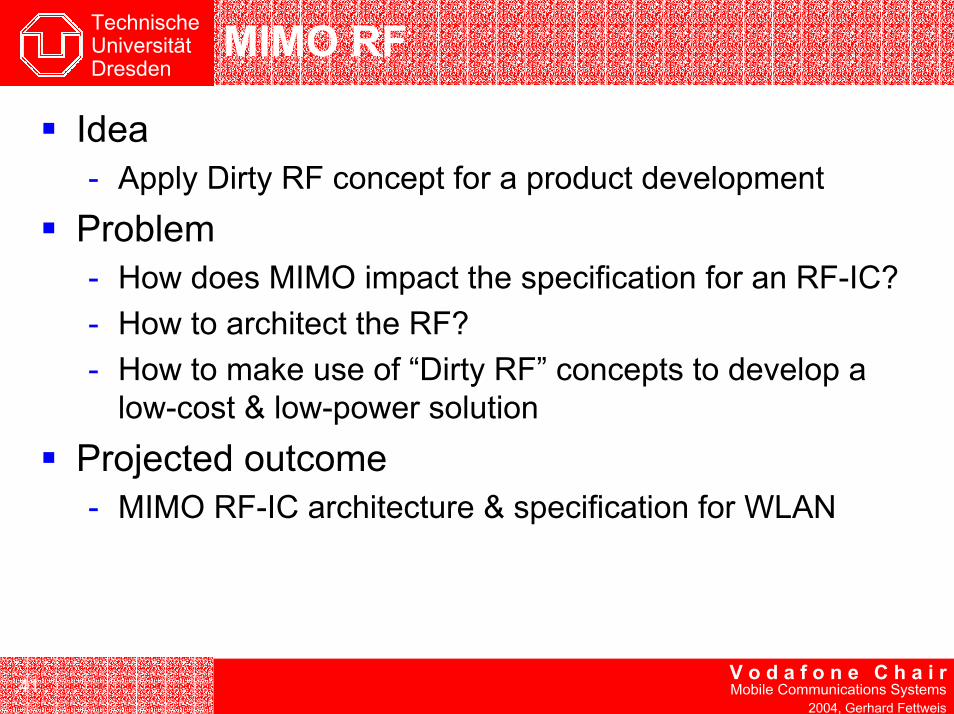
MIMO RF
Idea- Apply Dirty RF concept for a product development
Problem- How does MIMO impact the specification for an RF-IC?- How to architect the RF?- How to make use of “Dirty RF” concepts to develop a
low-cost & low-power solutionProjected outcome- MIMO RF-IC architecture & specification for WLAN

TechnischeUniversitätDresden
42V o d a f o n e C h a i rMobile Communications Systems
2004, Gerhard Fettweis
First Outcome of Dirty RF Concept:Coping With Phase Noise
Classical solution:- Phase noise should be uncorrelated
on each branch- Separate oscillators help improve
performance- M antennas
M x RF complexity
Dirty RF solution- Phase noise should be correlated on
each branch to improve tracking performance
- Single oscillator preferred- M antennas
M x RF signal chain complexity increase only
~A/D
&BB
Signal Processing
~
…
A/D &
BBSignal
Processing
~
…

TechnischeUniversitätDresden
V o d a f o n e C h a i rMobile Communications Systems
2004, Gerhard Fettweis
Power Amplifier & LNA

TechnischeUniversitätDresden
44V o d a f o n e C h a i rMobile Communications Systems
2004, Gerhard Fettweis
A Nonlinear Transmitter and AWGN I
Baseband Model:
• Matched RRC Filtering• Saleh PA Model• QPSK, 16-QAM, 16-PSK
0 0.2 0.4 0.6 0.8 10
0.2
0.4
0.6
0.8
1
1.2Saleh PA Model - Magnitude and Phase Distortion
Input Magnitude
Out
put M
agni
tude
, Out
put P
hase
MagnitudePhase

TechnischeUniversitätDresden
45V o d a f o n e C h a i rMobile Communications Systems
2004, Gerhard Fettweis
0 0.5 1 1.5 2 2.5 3 3.5 40
1
2
3
4
5
6Vector Addition in the Complex Plane
I
Qz(t)
n(t)
y(t)
10 12 14 16 18 20 22 24 2610
-6
10-5
10-4
10-3
10-2
10-1
SNR per Bit / [dB]
SE
R
Bayesian Estimation of Clipped OFDM Signals
w/o Estimatorwith Estimator• Polar Coordinates
• Bayesian Estimation ofMagnitude only
• Approximation ofby Noise Projection
| ( ) |y t
Bayesian Estimator for ClippedOFDM
Closed-Form Solution:
Performance Example:
• 2048 OFDM Carriers• IBO = 3 dB• 16-QAM

TechnischeUniversitätDresden
V o d a f o n e C h a i rMobile Communications Systems
2004, Gerhard Fettweis
I/Q Imbalance

TechnischeUniversitätDresden
47V o d a f o n e C h a i rMobile Communications Systems
2004, Gerhard Fettweis
Problem Definition
Ideal
90° PhaseI & Q-amplitude equals 1
Realistic
Phase imbalanceAmplitude imbalance
I
Q
I
Q’

TechnischeUniversitätDresden
48V o d a f o n e C h a i rMobile Communications Systems
2004, Gerhard Fettweis
Effects of IQ-Imbalance in a Low-IF Receiver
The beautiful world of theory:
X(f)
Desired channel
Strong adjacent channel
- fLO + fLO
Y(f)
fIF
Z(f)
x(t) z(n)y(n)ADCLP LP
LO IF
Equal amplitudePerfect phase match (90°)
Perfect 2-step I/Q downconversion

TechnischeUniversitätDresden
49V o d a f o n e C h a i rMobile Communications Systems
2004, Gerhard Fettweis
Effects of IQ-Imbalance in a Low-IF Receiver II
The brute world of reality:
X(f)
Desired channel
Strong adjacent channel
- fLO + fLO
Y(f)
fIF
Z(f)
x(t) z(n)y(n)ADCLP LP
LO IF
Mismatches inamplitudephase
Serious interference by the image signal

TechnischeUniversitätDresden
V o d a f o n e C h a i rMobile Communications Systems
2004, Gerhard Fettweis
ADC

TechnischeUniversitätDresden
51V o d a f o n e C h a i rMobile Communications Systems
2004, Gerhard Fettweis
Analysis of SNR limiting effects of (Nyquist-)ADCs
SNR performance limitsdue to:
thermal noiseaperture jitter
- sampling time errorscomparator ambiguity
- quantization errors due to limited comparator speed
Sample Rate (Samples/s) ~ 2xERBW (Hz)
SNR
bits
taken from: Walden, Robert H.: “Analog-to-Digital Converter Survey and Analysis.” IEEE JSAC-17(4), 1999.
For an effective resolution bandwidth (ERBW) range of about 1 MHz to 1 GHz aperture jitter is the dominating effect that limits the SNR of high resolution wideband ADCs.Clock Jitter has a similar effect on the SNR of (memoryless) ADCs.

TechnischeUniversitätDresden
52V o d a f o n e C h a i rMobile Communications Systems
2004, Gerhard Fettweis
Practically relevant case:input signal: mix of two sine waves with frequencies of 10 MHz and 100 MHz
constant error PSD (white noise floor)(independent of the input signal spectrum)
oversampling increases the jitter de-pendent SNR in a given frequency band(limit determined by line components)
aperture jitter clock jitter
weighted lines of the input PSD + Lorentzian spectra around themoversampling does not helpdifferent error power / SNR for equal-power spectral input components
Comparison of the error PSD –Simulation

TechnischeUniversitätDresden
V o d a f o n e C h a i rMobile Communications Systems
2004, Gerhard Fettweis
Finally

TechnischeUniversitätDresden
54V o d a f o n e C h a i rMobile Communications Systems
2004, Gerhard Fettweis
Dirty RFAperture Jitter
AmbiguityI/Q Imbalance
RRC mismatchFlicker Noise
Picking up “dirt”
Phase noise
-10 -5 0 5 10 15 20 25 300
0.5
1
1.5
2
2.5
3
3.5
416-QAM (AWGN) parameter ∆f3dB/∆fcar
SNR [dB]
cut-o
ff ra
te R
0 [bits
/sym
bol]
∆f3dB/∆fcar = 0
∆f3dB/∆fcar = 0.016
∆f3dB/∆fcar = 0.032
∆f3dB/∆fcar = 0.064
∆f3dB/∆fcar = 0.160
Nonlinear PA Nonlinear LNA

TechnischeUniversitätDresden
55V o d a f o n e C h a i rMobile Communications Systems
2004, Gerhard Fettweis
Conclusions
Today- Baseband guys require RF to be “perfect”- RF guys try to design best effort to achieve
specifications
RF Reality & Outlook- “Dirty RF” is becoming reality- Challenging task:
Combined RF-baseband solutionsto become possible

TechnischeUniversitätDresden
V o d a f o n e C h a i rMobile Communications Systems
2004, Gerhard Fettweis
And Now?
Putting thing together to achieve1Gb/s
At low cost

TechnischeUniversitätDresden
V o d a f o n e C h a i rMobile Communications Systems
2004, Gerhard Fettweis
Thanks !
10 Years Support
www.vodafone-chair.comIST Mobile Summit 2005 Announcement