wireless industrial sensor interface - home | bei sensors
TRANSCRIPT

Wireless industrialsensor interface

a secure robust Wireless interface With built-in reliability needed for real-time industrial control
The BEI SwiftComm wireless industrial sensor interface ushers in a new era of
wireless industrial control. Now the machine designer is free to install sensor
equipment without the expense and constraints of a hard-wired system.
Encoder installations in difficult applications like cranes, rotating tables or
mobile applications, are greatly simplified.
The SwiftComm system includes the transmitter-receiver pair, which
communicates using a point-to-point frequency-hopping 2.4 GHz RF protocol.
Because of its flexible input/output electronics, it can interface with many
different industrial sensors and control systems. Simply connect the SwiftComm
transmitter to the sensor and the SwiftComm receiver to your control system and
apply power. That’s it! No complicated cabling required.
SwiftComm’s proprietary radio protocols include a broad security code range,
data encryption, handshaking, interference recovery, and error checking that together
provides a secure and robust wireless interface system. Ruggedness and flexibility are further enhanced with
SwiftComm’s NEMA 4 weatherproof enclosures, panel mounting options, antenna choices and wide-range DC power inputs. SwiftComm is
available with an incremental or SSI output, or with an optional explosion proof transmitter housing (pictured above).
applicationsSwiftComm is suitable for use in a wide variety of industrial applications. However, certain conditions
allow the user to receive the most benefit from SwiftComm. In applications where long, expensive cable
lengths are needed, SwiftComm can provide a very cost effective alternative to hard wiring. If cabling
of any length is damaged often in a system and needs constant replacement, SwiftComm can be
a viable solution. SwiftComm is ideal for use in applications with a clear line-of-sight between
the transmitter and receiver. Although SwiftComm can work around some obstructions, the best
performance will be achieved where the radios have a clear line-of-sight. SwiftComm is a
very robust and reliable wireless interface system, and will work in many different kinds of
industrial applications. Here are just a few examples:
• crane & hoist
• drawbridge
• drawworks
• dam control
• irrigation
• mining
• Printing Press
• factory automation
a Wireless interface for real-time industrial controlUntil now, the only option available to connect encoders to controllers or PLCs has been by hard wiring. This approach has served the system
designer well in many applications. However, there are times where the cabling to the sensor is expensive to install, cumbersome, or creates a
maintenance problem. This is most evident when the encoder needs to move over large distances or is mounted to a rotating or mobile device.
Motion control applications require position and speed feedback in real time and as a continuous stream of data. Until now, wireless systems
have been unable to work with these applications due to high latency and signal interference. With most typical wireless systems, if packet
information is lost, the protocol requests for the information to be resent. This approach however slows down the flow of information from
transmitter to receiver, and adds an indeterminate amount of time delay to when the information is received. Add to this an undefined amount
of time required to process packets over a network protocol, such as Zigbee or Bluetooth, the resultant latency would seriously degrade time
sensitive data. Another even bigger threat is random interference that can destroy whole packets of information. All these factors have made
wireless systems for control unsuccessful…until now.
SwiftComm was designed from the ground up specifically to meet the demands of industrial motion control applications. It provides an
extremely robust wireless signal in real time over a secure network. SwiftComm is also equipped with several fail-safes to deal with signal
interference.

4 | BEI Sensors | swiftcomm installation manual and user Guide
robust signalBEI’s SwiftComm operates on the 2.4 GHz ISM radio band and
uses Adaptive Frequency Hopping Protocol (AFH). This helps avoid
data interruptions due to frequency interference. If a particular
radio channel encounters interference, SwiftComm seamlessly
hops to another open channel. This technology decreases the
susceptibility to interference thereby increasing overall reliability.
The SwiftComm hopping algorithm uses 77 ISM channels in a
pseudo-random sequence. To enhance RF link reliability even
more, when SwiftComm detects interference on a channel, that
channel is dropped from the hop sequence and SwiftComm will
avoid using that channel in the future. If the available channels list
ever becomes exhausted, previous dropped channels are retested
to see if they are clear.
SwiftComm’s patent pending technology can even overcome data
loss due to link interruption. Internally and transparent to the user,
SwiftComm keeps track of the encoder’s output signal. If
SwiftComm encounters packet loss from temporary link
interruption, it fills in the encoder’s output information
based on the historical data trend. It then processes
this information in place of the lost packet. SwiftComm
corrects for any accumulated error and seamlessly
sends the corrected data to the controller. So, even
in environments where occasional packets are lost,
SwiftComm will transmit a continuous stream of
data to the control system.
real time controlIt is critical in any motion control application to have minimum lag
time in signal transmission. Delays in data to the controller can
cause major problems. SwiftComm is one of the fastest wireless
sensor interfaces available. Data is relayed between the transmitter
and receiver every 600 microseconds (µs). Because SwiftComm is
a point-to-point configuration, there is minimal latency.
secure transmissionSwiftComm provides a very secure system for your data to travel
wirelessly. The transmitter and receiver each have a 40-bit
hard coded security code. These codes are programmed at the
factory and give the system a range of over 500 billion possible
unique codes. BEI has developed its own proprietary protocol
for SwiftComm, which is not available to the public. Additionally,
the data is transmitted with a high-level encryption algorithm
and pseudo-random frequency hopping. This provides additional
levels of data security to assure that your data
is protected.
long rangeBecause motion control applications can
vary widely, SwiftComm was designed
with a 50 mW radio. This provides
SwiftComm with reliable long-range
communication. In most open situations,
a reliable link distance of up to 1,000 feet
is possible. Inside buildings, a reliable link
distance on the order of 300 feet can be
expected.
basic setupThe SwiftComm Transmitter and Receiver modules operate as a pair,
known as Point-To-Point communication. Each pair shares a unique
security code, which is hard-coded at the factory and is not user
selectable. The full security code is not revealed on the modules’
labels and is stored by BEI. This is one of the many layers of security
provided by the SwiftComm architecture. If a replacement module
is needed, then the module’s serial number needs to be provided to
BEI in order to match the pair’s security code.
The basic configuration of the SwiftComm system begins with
connecting the Transmitter module to the encoder and connecting
the Receiver module to the control equipment. The Transmitter
sends the encoder signal wirelessly to the Receiver module, which
then passes this signal on to the controller. Even though the encoder
data travels one direction from Transmitter to Receiver, additional
information is exchanged between modules bi-directionally to keep
the modules in sync, maintain a quality RF link and to issue Built-
in-Test (B.I.T.) commands.
mountingThe SwiftComm modules have several mounting options. Each
module has two 1/4-20 UNC tapped holes on the back of enclosure
for mounting to flat surfaces. In addition, mounting ears are
available with front mount screws. For DIN rail mounting, a DIN rail
kit is available.
swiftcomm has a reliable range of up to 300 ft. indoors, and up to 1,000 ft. outdoors.
the transmitter and receiver should be installed so that
their antennas have a clear line of sight with each other.
sWiftcomm’s unique advantaGes setuP and oPeration
swiftcomm installation manual and user Guide | BEI Sensors | 5

GroundinG
siGnal and PoWer connections
antennas
6 | BEI Sensors | swiftcomm installation manual and user Guide
The LINK and STATUS lights indicate the quality of RF connection
between the modules. On startup, both Transmitter and Receiver
modules search their assigned RF spectrum for another module
with the same address. When the modules locate each other, they
exchange frequency hopping sequence and other housekeeping
information. Once finished with this exchange, the LINK light is
turned on.
From that point on, the Transmitter sends the data from the encoder
as a packet over the RF connection to the Receiver. The Receiver
reconstructs the encoder’s signal from the received packet and
informs the Transmitter of a successful packet exchange. This
series of events repeats each 600 microseconds.
LabeL CoLor DesCription
POWER GREEN ON Indicates input power is supplied to the Module
A RED Indicates quadrature Phase A status
B RED Indicates quadrature Phase B status
Z RED Indicates index status
LINK GREEN
ON Indicates SwiftComm Modules have established a reliable RF link. OFF Indicates the RF link has been lost and an B.I.T. signal is active
STATUS RED
Blinks ON each time RF packets are lost. Rate of blinking indicates relative quality of the RF link. Useful when setting up antennas and troubleshooting interference problems.
swiftcomm transmitter and receiver modules has a set of six front panel indicators that show internal operation and rf status.
requirementsSwiftComm is licensed for use with a 5.5 dBi gain dipole (rubber ducky)
with a reverse polarity TNC connector. These antennas are mounted
directly to the mating connectors on the SwiftComm modules and are
supplied with each Transmitter and Receiver module.
For reliable radio transmission, a secure and obstruction-free
antenna location is required. If the SwiftComm module itself can be
located away from metal obstructions, like steel beams and plates,
then the supplied antenna can be attached directly to the module’s
RF Port. Make sure the transmit and receive antennas have the
same orientation, either vertical or horizontal (vertical orientation
will provide better performance). If the module is mounted in a metal
enclosure or located near metal obstructions, an FCC-approved BEI
antenna extension accessory must be used, providing more flexible
antenna mounting options. This accessory includes a 10-foot coax
cable and ground plane mounting bracket.
To install the antenna extension, first secure the ground plane
mounting bracket as high up as possible and away from metallic
obstructions. Secure the coax cable to the bracket, attaching it to
the RF Port. Then secure the other end of the coax cable to the
SwiftComm module, attaching the cable connector to the module’s
RF Port. Attach the antenna to the antenna connector at the ground
plane mounting bracket. Make sure the transmit and receive
antennas have the same orientation (either vertical or horizontal).
esd ProtectionThe antenna inputs on the SwiftComm modules are equipped
with Transient Voltage Suppression (TVS) diodes. This is normally
adequate to protect the RF circuitry from static discharges and
mild lightning induced transients. However, if the antenna is to be
used outdoors where lightning is a much bigger threat, a lightning
arrestor such as an Altelicon AL-RTPRTJB-9SPL is recommended.
The arrestor is placed in-line with the antenna cable, and grounded
to a high integrity earth ground.
Important FCC Note: Only the 5.5 dBi gain dipole antenna, optional
BEI antenna extension accessory and optional lightning arrestor are
allowed for use with the SwiftComm modules. All other antenna
types and configurations are prohibited by the FCC license rules.
Consult the factory to discuss your application requirements.
SwiftComm transmitters and receivers are constructed with the
case connected to circuit common (0 V). Input signals are optically
isolated to provide exceptional noise immunity and significantly
reduce susceptibility to ground loop effects.
If the transmitter or receiver are mounted to a metal cabinet or
support structure, it is recommended that an insulator be added so
that the case is not electrically connected to Earth ground.
Electrical power and signal connections are located on the end
of the SwiftComm modules, opposite the antenna connector.
The modules are powered by a power supply with a minimum
of 5 VDC. The transmitter draws approximately 200mA, and the
encoder approximately 100mA. The encoder output logic needs to
be consistent with the transmitter input logic (5V, 12-15V or 24V
logic). The receiver draws approximately 200mA. The receiver
output logic type and levels should be selected consistent with the
input requirements of the PLC or computer receiving the signals.
Logic choices are 5 to 28V, a 5V regulated logic output (RS-422
and TTL compatible) with a 5 to 28 VDC supply, and an NPN open
collector output. All outputs are differential, with each channel
capable of sourcing or sinking 50 mA. If single-ended outputs
are needed, simply do not connect the complementary signals
(float them). Never connect any outputs directly to power, circuit
common, or another output, as this will cause an over-current in
the driver and likely lead to a thermal shutdown in the output stage.
swiftcomm installation manual and user Guide | BEI Sensors | 7
front Panel indicators
*Incremental Version shown. Available in Incremental or SSI versions

TransmitterReceiver
PWR
A
B
Z
LINK
STATUS
Encoder Output
Antenna
Receiver50mW 2.4GHz
ENCODER OUT
3.13
2.94
CONNECTOR:MS3102R18-1P
1.48TYP
1.00
CONNECTOR:RP-TNC
2.465
2.063
SWIVEL JOINT
ANTENNA 8.0" OVERALL LENGTH
BOTTOMVIEW
2X 1/4-20UNCX 1.5" DP. MAX.MOUNTING HOLES
0.88
2.05
NOTE:ALLOW 5.0" FROM
EDGE OF MODULE FORMS MATING CONN.
AND CABLE RADIUS
Encoder Input
LINK
STATUS
Transmitter50mW 2.4GHz
A
B
Z
Antenna
PWR
Pwr Input
1.00
CONNECTOR:MDC-5MR-PG9
1.003.13
2.94
1.48
POWER IN CABLE:MENCOM MDC-5FP-2M2 METERS LG.P/N: 924-31320-K52M
CONNECTOR:RP-TNC
1.05
1.97
SWIVEL JOINT
ANTENNA 8.0" OVERALL LENGTH
NOTE:ALLOW 3.0" FROMEDGE OF MODULE
FOR CABLE RADIUS
2X 1/4-20UNCX 1.5" DP. MAX.MOUNTING HOLES
2.063
2.465
BOTTOMVIEW
CABLE: 10.0'
CONNECTOR: MS3106F18-1S
ENCODER IN POWER IN
PG9 CABLE GLAND
2.05
The SwiftComm Transmitter Module has two connector plugs: a 5-pin connector for power input, B.I.T output and chassis ground; and a 3-meter cable with a 10-pin MS connector attached to the end.
The SwiftComm Receiver Module has an MS connector
that provides the same output signals as a standard
BEI encoder.
Input power can be from 5 to 28 VDC. Output signals
(specified at time of ordering) can be 5 VDC or V in.
The B.I.T output signals indicate the RF Link Status.
Case ground is connected to earth ground. Circuit
ground is electrically isolated from the case ground.
Both of these grounds are typically connected together
at the power supply.
8 | BEI Sensors | swiftcomm installation manual and user Guide swiftcomm installation manual and user Guide | BEI Sensors | 9
TransmitterReceiver
PWR
A
B
Z
LINK
STATUS
Encoder Output
Antenna
Receiver50mW 2.4GHz
ENCODER OUT
3.13
2.94
CONNECTOR:MS3102R18-1P
1.48TYP
1.00
CONNECTOR:RP-TNC
2.465
2.063
SWIVEL JOINT
ANTENNA 8.0" OVERALL LENGTH
BOTTOMVIEW
2X 1/4-20UNCX 1.5" DP. MAX.MOUNTING HOLES
0.88
2.05
NOTE:ALLOW 5.0" FROM
EDGE OF MODULE FORMS MATING CONN.
AND CABLE RADIUS
Encoder Input
LINK
STATUS
Transmitter50mW 2.4GHz
A
B
Z
Antenna
PWR
Pwr Input
1.00
CONNECTOR:MDC-5MR-PG9
1.003.13
2.94
1.48
POWER IN CABLE:MENCOM MDC-5FP-2M2 METERS LG.P/N: 924-31320-K52M
CONNECTOR:RP-TNC
1.05
1.97
SWIVEL JOINT
ANTENNA 8.0" OVERALL LENGTH
NOTE:ALLOW 3.0" FROMEDGE OF MODULE
FOR CABLE RADIUS
2X 1/4-20UNCX 1.5" DP. MAX.MOUNTING HOLES
2.063
2.465
BOTTOMVIEW
CABLE: 10.0'
CONNECTOR: MS3106F18-1S
ENCODER IN POWER IN
PG9 CABLE GLAND
2.05
sWiftcomm transmitter module sWiftcomm receiver module
*If transmission is interrupted for longer than 0.13 seconds the status of this pin will change from LO to HI. B.I.T. is HI at +V level.
*If transmission is interrupted for longer than 0.13 seconds the status of this pin will change from LO to HI. B.I.T. is HI at +V level.
Transmitter: Pwr Input & BIT Output (5 Pin Connector)
Pin Function Color1 +V (Supply Voltage) BRN
2 B.I.T Output* WHT
3 0V (Circuit Common) BLU
4 —— BLK
5 Case Ground GRY
Transmitter: Encoder Input (MS3106F18-1S or 10 ft pigtail)Pin Color (Pigtail) Incremental Function SSI FunctionA Yellow A DATA
B Blue B CLOCK
C Orange Z ——
D —— +V (Supply to Encoder) +V
E Black —— ——
F —— 0V (Supply to Encoder) 0V (Supply to Encoder)
G Wh/Yellow Case Gnd ——
H Wh/Blue A/ DATA
I Wh/Orange B/ CLOCK
J Z/ ——
Receiver Pinouts: Encoder Output (MS3102R18-1P)Pin Incremental Function SSI FunctionA A DATA
B B CLOCK
C Z ——
D +V (Supply Voltage) +V
E B.I.T Output* B.I.T Output*
F 0V (Circuit Common) 0V (Circuit Common)
G Case Gnd ——
H A/ DATA
I B/ CLOCK
J Z/ ——

Most troubleshooting can be accomplished by observing the
state of SwiftComm’s front panel lighted indicators. Following is
a description of the indicator lights and how to utilize them for
troubleshooting:
POWER: This indicator will turn on (green), if power between 5 and
28 VDC is being provided to the module. If this indicator is off,
check the power supply connections.
A, B, Z: These indicators turn on and off as the encoder’s
quadrature signals change state. While slowly turning the encoder,
observe if the A, B and Z indicators toggle on and off in a pattern.
If these indicators don’t respond, check the wiring to the encoder.
A differential encoder signal is required as an input to the module.
LINK: If a SwiftComm transmitter and receiver with the same
security code establishes radio contact with each other, then the
LINK indicator will turn on (green). The LINK indicator will turn off
if continuous radio contact is lost for more than 0.13 seconds
(about 200 packets). The B.I.T output follows the state of the LINK
indicator. Generally, the LINK indicator turns off for three reasons.
1. The RF signal is too weak. This can happen if the radios are too
far apart, or there is some obstruction, such as a building, between
the radios. Try reorienting the radios to avoid obstructions and/or
locating them closer together. Orient the antennas so they are both
vertical or horizontal. In a factory setting, Swiftcomm can typically
transmit reliably up to approximately 300 feet. In an outdoor setting,
that distance can increase to 1,000 feet. Contact the factory to
discuss your specific application environment.
2. The antenna is broken or not attached correctly. The antenna
should be securely tightened to the RF connector on both
SwiftComm modules. Also, inspect the coax wire inside the swivel
base of the antenna to make sure it is not frayed or broken.
3. A source of RF interference exists. Turn off different equipment
in the vicinity to see if the interference decreases, such as
Programmable Logic Controllers (PLC) and variable frequency
drives (VFD). If interference subsides when equipment is turned off,
try moving the source of interference or the SwiftComm modules to
another location. Also check that equipment covers and doors are
secured and the equipment is properly grounded to earth ground.
STATUS: Every 600 uS, the Transmitter sends a packet to the
Receiver with the current encoder data. The STATUS indicator
“flashes” each time an acknowledgment packet is lost. The more
packets lost, the more the STATUS indicator flashes. This makes
the STATUS indicator a good measure of signal quality. Normally
you would see about 1 or 2 flashes per second. This indicates
over a 99% packet success rate. This feature can be used during
initial set-up to optimize the location of the antennas, investigate
intervening obstructions and minimizing sources of interference.
SwiftComm radios are paired in a point-to-point configuration.
Encoder data is sent from the Transmitter module to the Receiver
module, where the data is passed on to the user’s equipment.
Because of this architecture, only one Transmitter and one Receiver
can share the same security code. Over 500 billion unique security
codes are available, assuring no address will ever be repeated.
Additionally, all radio pairs are programmed with their security
code at the factory and are not publicly available, which provides
enhanced security of each pair.
Data security was highly considered in the design of the SwiftComm
architecture. SwiftComm deploys three layers of protection to the data.
1. The radios use a pseudo-random adaptive frequency hopping
sequence, changing frequency every 600 uS. This random hopping
helps prevent unauthorized monitoring of the data stream.
2. The data sequence being transmitted between the SwiftComm
radios is proprietary, unlike common radio protocols such as Wi-Fi,
Zigbee or BlueTooth. These publicly known protocols are susceptible
to outside monitoring. SwiftComm’s protocol further enhances the
security of the data while being transmitted wirelessly.
3. SwiftComm uses a 40-bit encryption algorithm for an additional
layer of data protection from external monitoring.
I need a continuous, reliable encoder signal. What happens if the wireless signal is interrupted and
loses packets of data?
SwiftComm was designed specifically for critical motion control
applications. Its use of an Adaptive Frequency Hopping Protocol
(AFH) helps avoid data interruptions due to frequency interference.
If a particular radio channel encounters interference, SwiftComm
seamlessly hops to another open channel. This technology
decreases the susceptibility to interference, increasing overall
reliability.
Of course, in the real world, signal interference cannot be avoided
in all cases. Because of this, SwiftComm uses patent pending
technology that can overcome data loss due to link interruption.
Internally and transparent to the user, SwiftComm keeps track of
the encoder’s output signal. If SwiftComm encounters packet loss
from temporary link interruption, it fills in the encoder’s output
information based on the historical data trend. It then processes
this information in place of the lost packet. When a valid packet of
information is received, SwiftComm determines any accumulated
error and corrects the quadrature signal to the controller. So even
in environments where occasional packets are lost, SwiftComm will
transmit a seamless stream of data to the control system.
I’m concerned with the security of my data being transmitted wirelessly. Will SwiftComm protect my
data?
Yes. SwiftComm provides a very secure system for your data to
travel wirelessly. The transmitter and receiver each have a 40-bit
hard coded security code. These codes are programmed at the
factory and give the system a range of over 500 billion possible
unique codes. BEI has developed its own proprietary protocol for
SwiftComm, which is not available to the public. Additionally, the
data is transmitted with a high-level encryption algorithm and
pseudo-random frequency hopping. This provides additional levels
of data security to assure that your data is protected.
What type of encoder can SwiftComm interface with?
SwiftComm can interface with any quadrature incremental or SSI
absolute encoder with differential outputs.
I have an application using a high-speed encod-er. What kind of latency will I experience with
SwiftComm?
It is critical in any motion control applications to have minimum
lag time in signal transmission. Delays in data to the controller can
cause major problems. SwiftComm is one of the fastest wireless
sensor interfaces available. Data is relayed between the transmitter
and receiver every 600 microseconds (µs). Because SwiftComm
is a point-to-point configuration, there is little inherent latency,
typically about 1mS.
I have an outdoor application and my encoder cables continually need replacement due to this
harsh environment. Is SwiftComm an option for me?
Absolutely. The SwiftComm transmitter and receiver are both
encased in NEMA 4 cast aluminum enclosures. They are also
powder coated with a gasketed cover. This gives them excellent
protection from windblown dust and rain, splashing water and the
formation of ice on the enclosures.
What is the maximum distance I can transmit my
encoder data wirelessly with SwiftComm?
Like all wireless systems, the maximum transmission distance
depends on the environment where the transmitter and receiver are
being installed. On a factory floor, where there is high electrical noise
and metal obstructions, we typically see reliable communications
up to 300 feet. Outdoors, with line-of-sight and relatively few
sources of interference, this increases to over 1,000 feet.
Can multiple SwiftComm pairs operate in the same
area without interfering with each other?
Yes. Each pair shares a unique security code which ensures they
will not interfere with other SwiftComm pairs in the area. These
codes are programmed at the factory and give the system a range
of over 500 billion possible unique codes. Additionally, SwiftComm
utilizes Adaptive Frequency Hopping (AFH) protocol. If a radio band
is being used by one SwiftComm pair, the other SwiftComm pair
seamlessly hops to another open channel. This helps avoid data
interruptions due to frequency interference.
10 | BEI Sensors | swiftcomm installation manual and user Guide swiftcomm installation manual and user Guide | BEI Sensors | 11
security code
encryPtion and data security
troubleshootinG
sWiftcomm faqs
THE AMERICAS
1461 Lawrence Dr | Thousand Oaks, CA 91301 USA
Tel: 800-350-2727 or 805-716-0322
www.beisensors.com
©2016 BEI Sensors | Rev 12-16
Backed by Extensive International ResourcesSensata Technologies is one of the world’s leading suppliers ofsensing, electrical protection, control and power managementsolutions with operations and business centers in 16 countries.Sensata’s products improve safety, efficiency and comfort formillions of people every day in automotive, appliance, aircraft,industrial, military, heavy vehicle, heating, air-conditioning andventilation, data, telecommunications, recreational vehicle andmarine applications
For more information please visit Sensata’s website atwww.sensata.com.
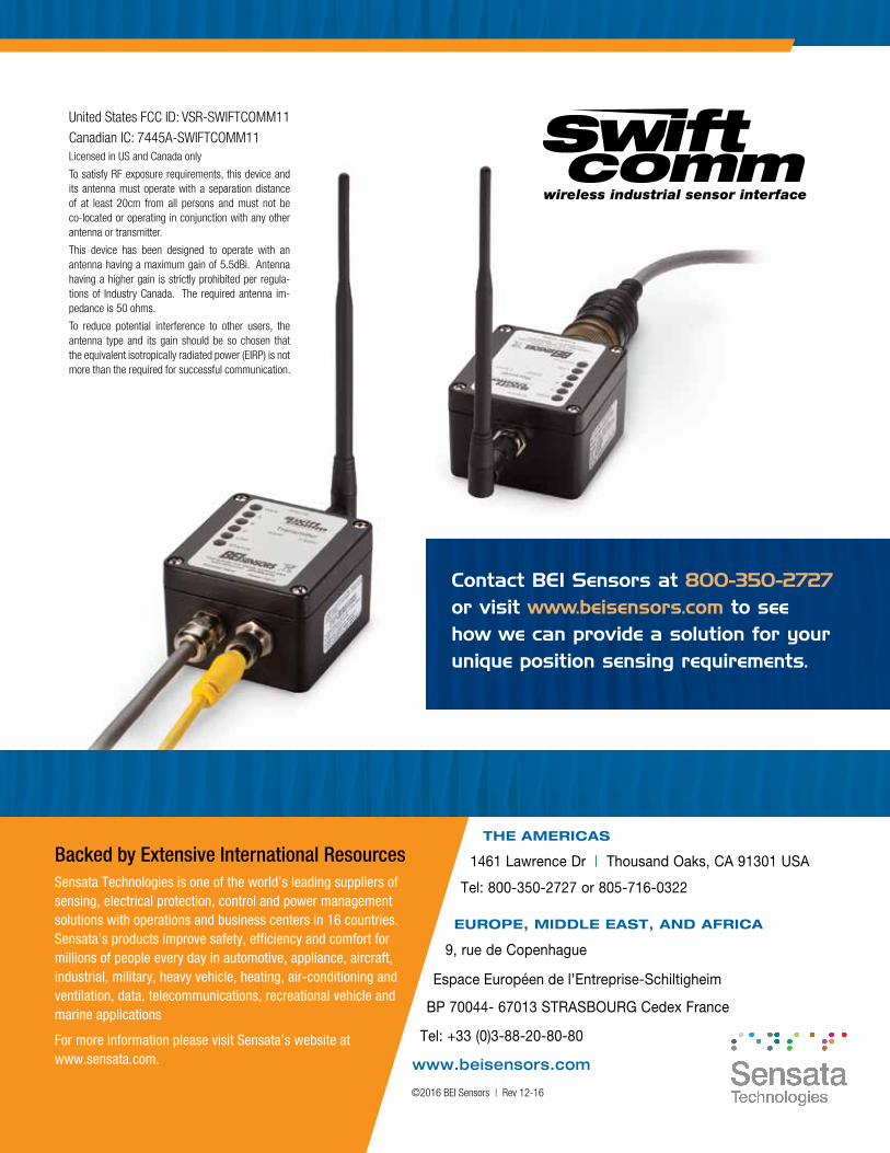
contact bei sensors at 800-350-2727 or visit www.beisensors.com to see how we can provide a solution for your unique position sensing requirements.
United States FCC ID: VSR-SWIFTCOMM11
Canadian IC: 7445A-SWIFTCOMM11Licensed in US and Canada only
To satisfy RF exposure requirements, this device and its antenna must operate with a separation distance of at least 20cm from all persons and must not be co-located or operating in conjunction with any other antenna or transmitter.
This device has been designed to operate with an antenna having a maximum gain of 5.5dBi. Antenna having a higher gain is strictly prohibited per regula-tions of Industry Canada. The required antenna im-pedance is 50 ohms.
To reduce potential interference to other users, the antenna type and its gain should be so chosen that the equivalent isotropically radiated power (EIRP) is not more than the required for successful communication.
EUROPE, MIDDLE EAST, AND AFRICA
9, rue de Copenhague
BP 70044- 67013 STRASBOURG Cedex France
Tel: +33 (0)3-88-20-80-80
Espace Européen de l’Entreprise-Schiltigheim