wireless non-contact cardiac and neural...
TRANSCRIPT

Wireless Non-contact Cardiac and Neural Monitoring
Yu M. Chi, Patrick NgDepartment of Electrical and
Computer EngineeringUniversity of California, San
Diego9500 Gilman DriveLa Jolla, CA 92093
m1chi, [email protected]
Eric Kang, Joseph KangDepartment of BioengineeringUniversity of California, San
Diego9500 Gilman DriveLa Jolla, CA 92093
Jennifer FangDepartment of ComputerScience and Engineering
University of California, SanDiego
9500 Gilman DriveLa Jolla, CA 92093
[email protected] Cauwenberghs
Department of BioengineeringUniversity of California, San
Diego9500 Gilman DriveLa Jolla, CA [email protected]
ABSTRACTUbiquitous physiological monitoring will be a key drivingforce in the upcoming wireless health revolution. Cardiacand brain signals in the form of ECG and EEG are two crit-ical health indicators that directly benefit from long-termmonitoring. Despite advancements in wireless technologyand electronics miniaturization, however, the use of wirelesshome ECG/EEG monitoring is still limited by the inconve-nience and discomfort of wet adhesive electrodes.
We have developed a wireless biopotential instrumenta-tion system using non-contact capacitive electrodes that op-erate without skin contact. The sensors can be embeddedwithin comfortable layers of fabric for unobtrusive use. Allof the issues relating to the design of low noise, high perfor-mance capacitive sensors are discussed along with full tech-nical details, circuit schematics and construction techniques.
The non-contact electrode has been integrated into botha wearable ECG chest harness as well a EEG headband.We have also designed a compact, battery-powered, wirelessdata acquisition system to interface with multiple electrodesand monitor patient cardiac and neural signals in real time.Experimental data shows that the non-contact capacitiveelectrode perform comparable to Ag/AgCl electrodes usingour special chest harness and head bands to ensure tight,movement-free electrode positioning.
General TermsEEG, ECG, Wireless Health, Capacitive Sensors
Permission to make digital or hard copies of all or part of this work forpersonal or classroom use is granted without fee provided that copies arenot made or distributed for profit or commercial advantage and that copiesbear this notice and the full citation on the first page. To copy otherwise, torepublish, to post on servers or to redistribute to lists, requires prior specificpermission and/or a fee.Wireless Health 2010, October 5−7, 2010, San Diego, USACopyright 2010 ACM 978-1-60558-989-3 ...$10.00.
1. INTRODUCTIONBrain and cardiac biopotential signals in the form of EEG
and ECG are two critical physiological indicators that aredirectly suited for long-term wireless health monitoring. Yetdespite advancements in wireless technology and electronicsminiaturization, however, the use EEG/ECG has still beenlargely limited by the inconvenience and discomfort of con-ventional wet contact electrodes.
For home use, clinical grade adhesive electrodes are oftencited as irritating and uncomfortable leading to low usagecompliance. As an alternative, dry electrodes [1] [2] havestarted becoming much more common-place. However, likewet electrodes, dry electrodes still require direct electricalcontact to the skin. In addition, dry electrodes, which do nothave the benefit of a conductive gel, are much more sensitiveto the condition of the skin and are highly susceptible tomotion artifacts. For future wireless health systems, a lessobtrusive sensor is needed to match the advancements madein wireless technology.
In contrast to wet and dry contact sensors, non-contactcapacitive electrodes do not require an ohmic connectionto the body. This offers numerous advantages since non-contact electrodes require zero preparation, are completelyinsensitive to skin conditions and can be embedded inside agarment for a completely unobtrusive, patient-friendly sys-tem. While the concept of non-contact biopotential sensorsis not new, with the first working device reported decadesago [3], a practical device for patient use has yet to materi-alize. More recently, several authors have presented resultsfrom designs utilizing the latest in commercially availablediscrete low noise amplifiers [4] [5] [6], including some wire-less designs [7].
Over the years, many clever designs have appeared, someproprietary. However, nothing has really progressed beyondthe ’lab prototype’ stage. In addition, general knowledgeabout capacitive sensors and how to design and constructthem are scarce in literature. In this paper, we attempt toaddress these shortcomings by presenting the full designs,including all the relevant details in the analog front-end,

+ +
+
+
Vref
10nF
1M
10k
1001M 1nF
10k
LMP7702/A
10k
1M
1nF
+ +
+
Vref
10nF
1M
10k
1001M 1nF
10k
+10k
10k
Vref
Vcm
CLOCK
DATA
CONVERT
Ain
ADS7685
Ain
16b ADC
CONVERT
DATA
CLOCK
Electrode 1
Electrode 2
Capacitive DRL
Differential Channel 1
Differential Channel 2
N-ElectrodesN-Channels
LMP7702/B
LMP7702/A
LMP7702/B
LMP7704/A
LMP7704/B
LTC6081/A
LTC6081/B
ADS7685
16b ADC
PIC24microcontroller100k
Body
InsulationFigure 1: Full schematic of wireless ECG/EEG system. The capacitive electrode PCB contains the front-endamplifier. Differential gain, digitization, active grounding and digital processing/wireless is contained onseparate base unit.
AmplifierSnap Connector
Active Shield(inner layer)
Sensing Plate(bottom)
Figure 2: Picture of the non-contact, capacitive elec-trode. The sensor is manufactured on a standardPCB, which contains the amplifier circuits on thetop and the sensing plate on the bottom.
for a high-quality, contactless, wireless ECG/EEG monitor.In addition, we characterize the system-level performanceby directly comparing the capacitive electrode against tra-ditional, clinical Ag/AgCl electrodes and show that theyperform equally well in many applications.
2. SYSTEM DESIGNA full schematic depicting the wireless, non-contact sen-
sor system is shown in Figure 1. Each capacitive electrodecontains an onboard amplifier, filter, buffer and connectsto the wireless base unit. The full operation of the capaci-tive electrode’s amplifier and analog front-end, including cir-cuit/noise theory, has been well described in previous pub-lications [8] [9]. In this paper, we focus on the system-leveldesign and results from our latest generation, optimized sen-sor.
All of the electrodes, including the active ground, can befully insulated. Since no galvanic connection is present andthe device is battery powered, the system is very patient-friendly and safe to use.
2.1 Non-contact ElectrodesThe basic design and function of capacitive electrodes has
been well explored and documented in the literature, with
0 0.5 1 1.5
0
0.5
1
1.5
2Driven Capacitive Ground
Volta
ge (m
V)
Time (S)0 0.5 1 1.5
0
0.5
1
1.5
2Driven Dry Ground
Volta
ge (m
V)
Time (S)
0 0.5 1 1.5
0
0.5
1
1.5
2Passive Dry Ground
Volta
ge (m
V)
Time (S)0 0.5 1 1.5
0
0.5
1
1.5
2Floating Ground
Volta
ge (m
V)
Time (S)
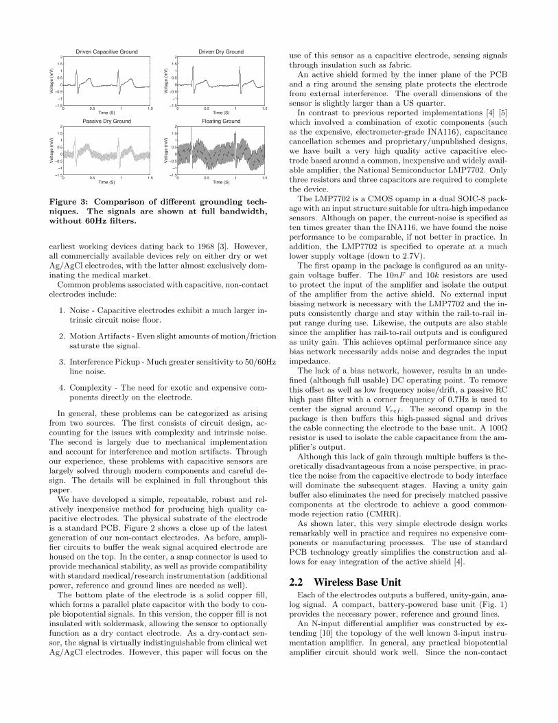
Figure 3: Comparison of different grounding tech-niques. The signals are shown at full bandwidth,without 60Hz filters.
earliest working devices dating back to 1968 [3]. However,all commercially available devices rely on either dry or wetAg/AgCl electrodes, with the latter almost exclusively dom-inating the medical market.
Common problems associated with capacitive, non-contactelectrodes include:
1. Noise - Capacitive electrodes exhibit a much larger in-trinsic circuit noise floor.
2. Motion Artifacts - Even slight amounts of motion/frictionsaturate the signal.
3. Interference Pickup - Much greater sensitivity to 50/60Hzline noise.
4. Complexity - The need for exotic and expensive com-ponents directly on the electrode.
In general, these problems can be categorized as arisingfrom two sources. The first consists of circuit design, ac-counting for the issues with complexity and intrinsic noise.The second is largely due to mechanical implementationand account for interference and motion artifacts. Throughour experience, these problems with capacitive sensors arelargely solved through modern components and careful de-sign. The details will be explained in full throughout thispaper.
We have developed a simple, repeatable, robust and rel-atively inexpensive method for producing high quality ca-pacitive electrodes. The physical substrate of the electrodeis a standard PCB. Figure 2 shows a close up of the latestgeneration of our non-contact electrodes. As before, ampli-fier circuits to buffer the weak signal acquired electrode arehoused on the top. In the center, a snap connector is used toprovide mechanical stability, as well as provide compatibilitywith standard medical/research instrumentation (additionalpower, reference and ground lines are needed as well).
The bottom plate of the electrode is a solid copper fill,which forms a parallel plate capacitor with the body to cou-ple biopotential signals. In this version, the copper fill is notinsulated with soldermask, allowing the sensor to optionallyfunction as a dry contact electrode. As a dry-contact sen-sor, the signal is virtually indistinguishable from clinical wetAg/AgCl electrodes. However, this paper will focus on the
use of this sensor as a capacitive electrode, sensing signalsthrough insulation such as fabric.
An active shield formed by the inner plane of the PCBand a ring around the sensing plate protects the electrodefrom external interference. The overall dimensions of thesensor is slightly larger than a US quarter.
In contrast to previous reported implementations [4] [5]which involved a combination of exotic components (suchas the expensive, electrometer-grade INA116), capacitancecancellation schemes and proprietary/unpublished designs,we have built a very high quality active capacitive elec-trode based around a common, inexpensive and widely avail-able amplifier, the National Semiconductor LMP7702. Onlythree resistors and three capacitors are required to completethe device.
The LMP7702 is a CMOS opamp in a dual SOIC-8 pack-age with an input structure suitable for ultra-high impedancesensors. Although on paper, the current-noise is specified asten times greater than the INA116, we have found the noiseperformance to be comparable, if not better in practice. Inaddition, the LMP7702 is specified to operate at a muchlower supply voltage (down to 2.7V).
The first opamp in the package is configured as an unity-gain voltage buffer. The 10nF and 10k resistors are usedto protect the input of the amplifier and isolate the outputof the amplifier from the active shield. No external inputbiasing network is necessary with the LMP7702 and the in-puts consistently charge and stay within the rail-to-rail in-put range during use. Likewise, the outputs are also stablesince the amplifier has rail-to-rail outputs and is configuredas unity gain. This achieves optimal performance since anybias network necessarily adds noise and degrades the inputimpedance.
The lack of a bias network, however, results in an unde-fined (although full usable) DC operating point. To removethis offset as well as low frequency noise/drift, a passive RChigh pass filter with a corner frequency of 0.7Hz is used tocenter the signal around Vref . The second opamp in thepackage is then buffers this high-passed signal and drivesthe cable connecting the electrode to the base unit. A 100Ωresistor is used to isolate the cable capacitance from the am-plifier’s output.
Although this lack of gain through multiple buffers is the-oretically disadvantageous from a noise perspective, in prac-tice the noise from the capacitive electrode to body interfacewill dominate the subsequent stages. Having a unity gainbuffer also eliminates the need for precisely matched passivecomponents at the electrode to achieve a good common-mode rejection ratio (CMRR).
As shown later, this very simple electrode design worksremarkably well in practice and requires no expensive com-ponents or manufacturing processes. The use of standardPCB technology greatly simplifies the construction and al-lows for easy integration of the active shield [4].
2.2 Wireless Base UnitEach of the electrodes outputs a buffered, unity-gain, ana-
log signal. A compact, battery-powered base unit (Fig. 1)provides the necessary power, reference and ground lines.
An N-input differential amplifier was constructed by ex-tending [10] the topology of the well known 3-input instru-mentation amplifier. In general, any practical biopotentialamplifier circuit should work well. Since the non-contact

Sensor
Wireless Base
ECG Vest EEG Headband
Figure 4: Picture of the prototype ECG chest vest and EEG head band.
1mV
1s
3M Red Dot Ag/AgCl
Figure 5: Detailed comparison of signal acquired si-multaneously from a set of clinical grade 3M RedDot Ag/AgCl adhesive electrodes and the non-contact sensor. The non-contact sensor was placedover a cotton t-shirt.
electrodes are AC coupled with low-offset buffers, it waspossible to incorporate a large amount of gain (40dB) di-rectly within one amplifier stage. A 16-bit ADC (AD7685)is used, resulting in a LSB of 0.5µV over an input range of33mV .
A two pole passive RC filter is used to filter out high-frequency components before the ADC. Both corner frequen-cies are set at 159Hz. Although the anti-alias filter providesonly a shallow roll-off, we use a sufficiently high samplingrate to avoid any noticeable aliasing artifacts. This alsominimizes the number of passive and active components.
The overall bandwidth of the system is then dictated bythe analog high-pass filter of the capacitive electrode, 0.7Hz,and the antialias filter, 159Hz.
2.3 GroundingSubject grounding is one of the most important factors
in achieving good signal quality. Unfortunately, it is oftenoverlooked and not always explained clearly, despite its vitalimportance. In our experience, many of the problems withnon-contact sensors were due to improper grounding.
In line with the idea of a fully insulated system, we usea capacitive coupling to connect the circuit ground back tothe body. A dummy electrode without components is usedto as the capacitive ground electrode. Such a ground is fullyinsulated, but offers only a weak coupling, rendering the sys-tem susceptible to interference. Actively driven groundingschemes are a well-known technique [11] to reduce common-mode interference and have been successfully adapted for
0 5 10 15 20 250.4
0.5
0.6
0.7
0.8
0.9
1
ECG
Inte
rbea
t Int
erva
l (S)
Time (S)
Sitting
Walking
Running
Jumping
Figure 6: Extracted heart beat (R-R) intervals fromthe ECG signal for the Ag/AgCl sensors versus thenon-contact sensor prototype. The intervals are es-sentially identical.
capacitive sensors [12].On the base unit, the common mode signal, Vcm is con-
nected to an inverting amplifier with gain of -100 to providean additional 40dB of CMRR for the system. The signalis fed back into the body through the dummy ground elec-trode.
An simple experiment, depicted in Figure. 3 illustratesthe effectiveness of this active ground. The capacitive activeground is as effective as a driven dry ground contact (anti-static wrist strap). Passive dry grounds start to suffer from60Hz noise pick-up. A floating (purely parasitic) groundmay also be used, but suffers from large 60Hz and otherlow frequency artifacts, and is not suitable for any seriousmeasurements.
The combination of the active ground and the fact thatthe system is battery-powered, results in a very clean signal,free from 60Hz noise.
2.4 Data AcquisitionA simple 16-bit microcontroller (PIC24) was used to con-
trol the ADC. The base unit supports both Bluetooth wire-less connectivity for live streaming of data to a PC or otherdisplay interface. For longer-term mobile recordings, a mi-croSD interface is also available. The entire system is pow-ered from a 900mAh rechargeable lithium-polymer battery

0 2 4 6 8 101.5
1
0.5
0
0.5
1
1.5
2Sitting
Time (S)
Volta
ge (m
V)
0 2 4 6 8 101.5
1
0.5
0
0.5
1
1.5
2Walking
Time (S)
Volta
ge (m
V)
0 2 4 6 8 101.5
1
0.5
0
0.5
1
1.5
2Running
Time (S)
Volta
ge (m
V)
0 2 4 6 8 101.5
1
0.5
0
0.5
1
1.5
2Jumping
Time (S)
Volta
ge (m
V)
Figure 7: A 10-second long comparison of signal from 3M Red Dot (red trace) versus non-contact electrodes(black trace) during various activities. The non-contact electrodes were fixed in a tight chest band on top ofa cotton shirt.
good for approximately 10 hours of continuous recording.The device is recharged through a mini-USB connector. A
USB-RS232 converter (FT232R) is also available for higherbandwidth, real-time streaming of data than what is possi-ble with the Bluetooth application. For safety reasons, thismode should only be used with an unplugged laptop, sinceno power isolation circuit is provided.
For the purposes of the experiments in this paper, weutilized the Bluetooth transmitter which streamed data intoa simple PC display and logging application at a rate of343Hz for the four signal channels.
For future, commercial-grade systems, it would be advan-tageous to use the latest in low-power wireless technology(ie. Bluetooth low-energy) as well as miniaturize the sys-tem’s form-factor.
3. WEARABLE SENSOR HARNESSAs mentioned earlier, capacitive electrodes do not have the
benefit of being fixed to body. Consequently, they are verysensitive to motion errors and require a robust enclosure toachieve an optimal signal.
We have developed an ECG chest harness and an EEGheadband (Fig. 4) to mount the non-contact electrodes. Asshown later, a firm enclosure that fixes the electrodes to thebody allows the non-contact electrode to perform almost aswell as standard adhesive Ag/AgCl electrodes.
A compression vest was used as the basis of the ECG
chest harness. Adaptation of the gynecomastia vest wasprepared by sewing electrode snap connectors onto the vestand snapping the electrodes during use. Non-contact elec-trode placement was assigned to the two midaxillary posi-tions. This vest was ideal for electrode placement due toits elastic contouring ability, covering of the thoracic surfacewith sufficient firmness. A second elastic band was also op-tionally available to add additional security for holding theelectrodes in place.
For EEG experiments, a simple, tight, elastic cloth head-band was used in a similar fashion by sewing in snap con-nectors for the non-contact electrodes. In contrast to knowncommercial and research headbands, our version allows forsignals to be acquired through hair using the capacitive elec-trodes. The design and operation of the EEG headband wasespecially challenging due to the flexible properties of hairwhich make securing the electrodes difficult.
4. PHYSIOLOGICAL DATAThe ECG vest and EEG headband were used to collect
live data using the capacitive sensors. For the purposes ofgenerating a direct comparison, two of the four electrodeinputs were connected to standard passive Ag/AgCl (3MRed Dot) and the other two were connected to the capac-itive active electrodes. The subject was a healthy 21 yearold male. Experiments were conducted in a standard elec-trical engineering lab with no effort to eliminate sources of

0 1 2
2
0
2I
0 1 2
2
0
2II
0 1 2
2
0
2III
0 1 2
2
0
2aVL
0 1 2
2
0
2aVR
0 1 2
2
0
2aVF
0 1 2
2
0
2V1
0 1 2
2
0
2V2
0 1 2
2
0
2V3
0 1 2
2
0
2V4
0 1 2
2
0
2V5
0 1 2
2
0
2V6
Figure 8: Derived 12-lead ECG from 4-electrode chest band in an EASI array.
interference.
4.1 ECG ExperimentsFor the ECG tests, the capacitive electrodes were mounted
into the tight, body-fitting harness with the two capacitiveelectrodes on the left and right sides of the ribcage. Thesubject wore a simple cotton t-shirt underneath the har-ness. Two Ag/AgCl adhesive electrodes were also placed ina nearby position directly on the skin. The output signalfor the capacitive sensor was defined by taking the differ-ence between the two and likewise of the Ag/AgCl electrodepair.
Figure 5 shows a detailed plot of a ECG sample takenwhile the subject was sitting at rest. The overall signalsare nearly indistinguishable in both shape and noise lev-els, even though the capacitive electrodes were operatingthrough clothing. All relevant ECG features are clearly vis-ible. The slightly smaller amplitude of the signal from thenon-contact electrode is likely due to the signal attenuationfrom the extremely high source impedance.
One previous study [6] compared the performance of aproprietary capacitive electrode design versus contact elec-trodes with a subject lying down. We extend the methodol-ogy established in these tests to include data with an activelymoving subject. Figure 7 shows 10-second plots comparingthe signal acquired from the capacitive and Ag/AgCl elec-trodes.
As expected, the signal remains mostly undisturbed whilethe subject is at rest and walking lightly. During more vigor-ous activities, motion artifacts become problematic for bothelectrodes types, rendering the ECG signal useful for onlyR-R beat detection. The signal for the capacitive electrodeis not substantially worse, as long as the capacitive elec-trodes are fixed tightly against the body using the harness.It should be worth noting, however, that capacitive elec-trodes are extremely sensitive to friction (rubbing againstcotton), which necessitates the hight chest harness.
We again used the same methodology as [6] to comparethe extracted R-R beat intervals to show the equivalence ofAg/AgCl and capacitive electrodes, extending their studyto subjects in motion. The plot is shown in Figure 6. Theextracted R-R beat intervals are virtually identical acrossall the tested activities.
For applications beyond simple heart beat and rhythmdetection, a clinical-grade multi-lead signal is required. Weused the four input channels available from our device toconstruct an EASI [13] array to obtain a derived 12-lead
ECG signal. The positioning and transformation coefficientswere taken from [13].
Placement of electrodes at standard EASI positions andground was accomplished by use of the adapted gynecomas-tia vest. Figure 8 shows the derived 12-lead ECG, whichshow the expected shape and features, such as the increas-ing amplitude of the R-wave progressing from the V1 to V6lead.
4.2 EEG ExperimentsSimilar to the cardiac data, two of the input channels
were connected to Ag/AgCl adhesive electrodes to achievea direct comparison with the non-contact sensors. For theEEG experiments, one capacitive electrode was placed onthe forehead (Fp1) and the second on the back (Oz), throughhair. Likewise, an Ag/AgCl electrode was also placed onthe forehead (Fp2). However, since it was not possible toplace an contact electrode through hair, the second Ag/AgClelectrode was placed on the mandible (A1). Unless specified,the output for each electrode was defined as the signal ateach channel minus the common-mode of four channels.
Figure 9 shows a detailed time-domain plot of all fourEEG channels with the subject relaxing, at rest with closedeyes. Not only are the expected alpha rhythms clearly vis-ible (especially in the occipital electrode), the signals fromthe Ag/AgCl and capacitive electrodes are virtually identi-cal. Strong alpha wave activity is seen, as expected for anawake, relaxed subject. The signals are all shown at fullbandwidth, without an additional digital filtering showingthe effectiveness of the active shield and driven ground.
A second montage consisting of two signals was obtainedby using the A1 Ag/AgCl electrode as a reference for thefrontal and parietal capacitive electrodes. In this experi-ment, the subject was asked to blink several times and thenclose his eyes. Figure 10 shows the clear blink artifacts inthe Fp1A1 signal followed by the onset of alpha waves in theOzA1 signal.
The ability to easily obtain signals from the normally haircovered occipital and parietal regions is especially useful forbrain-computer (BCI) and other EEG-based neural inter-faces. Systems which can only obtain frontal EEG activ-ity cannot obtain important responses including the P300evoked potential and the stead-state visual evoked poten-tials (SSVP), commonly used in BCI applications.
To test the effectiveness of the capacitive electrode overthe haired occipital region, a simple experiment where thesubject was asked to watch a flashing LED was devised to

1s
100!V!"#!"$%&'&()*+,-%
$-.-/0,012&'&()*+,-%
$-.-/0,012&'&3//0.0,-%
!"#!"$%'&4-+506%2
Figure 9: Close-up of EEG signals acquired using a mix of Ag/AgCl (3M Red Dot) and capacitive non-contactelectrodes. No extra filtering beyond the analog anti-alias has been applied to the raw signal to show thatthe sensor is free from 60Hz interference.
100!V
1s
Non-contact Occipital
Non-contact Frontal
Blink Blink Blink Blink
Alpha Activity/Eyes Closed
Figure 10: Experiment showing the signal from the frontal capacitive electrode (Fp1A1) in blue and the signalfrom the occipital capacitive electrode (O1A1). Eye blink artifacts are visible in the frontal electrodes duringthe first half of the recording. Strong alpha activity is seen in the occipital electrode after the subject’s eyesclose.
measure the SSVP response.Sleep diagnosis is an important medical application of
EEG technology, and one that will directly benefit fromhaving easy to use, unobtrusive, non-contact sensors. Homesleep monitoring and coaching systems are already commer-cially available but rely on the limited set of signals availablefrom forehead contact electrodes. The non-contact sensor al-lows for EEG signals to be acquired from the entire head,without gels.
A spectrogram depicting a period of sleep EEG taken fromthe O1 capacitive electrode is shown in Figure. 11. The sub-ject was asked to take a short nap. The different frequencycomponents of sleep EEG activity are visible in the time-frequency plot.
5. CONCLUSIONWe present the full designs for a wireless ECG/EEG mon-
itoring system using insulated, non-contact sensors.
Non-contact sensors have traditionally been thought of asunsuitable for medical-grade applications, but we demon-strate how careful design, both at the circuit and systemlevel can produce signals comparable to clinical grade Ag/AgClelectrodes for both ECG and EEG applications. The onearea that is still currently unaddressed, however, is sen-sitivity to motion artifacts. Efforts directed at mitigat-ing the non-contact electrode’s inherent sensitivity to mo-tion/friction effects at the system and signal processing levelis expected to yield large returns for this field.
This wireless and wearable system is ideally suited forfuture mobile health applications by being much more com-fortable and patient-friendly than traditional contact basedsystems.
6. ACKNOWLEDGEMENTSThis work was generously supported by National Semicon-
ductor and NSF SBE-0847752. The authors thank Dong-mei

Time (s)
Figure 11: Spectrogram of sleep EEG taken with theheadband. The signal is taken from the non-contactelectrodes (Fp1O1).
Yan and Mehmet Alsan at National for their support andfruitful discussions. We also thank Siddharth Joshi for helpwith setting up experimentation.
7. REFERENCES[1] T.J. Sullivan, S.R. Deiss, Tzyy-Ping Jung, and
G. Cauwenberghs. A brain-machine interface usingdry-contact, low-noise eeg sensors. In Circuits andSystems, 2008. ISCAS 2008. IEEE InternationalSymposium on, pages 1986 –1989, 18-21 2008.
[2] Emil Valchinov and Nicolas Pallikarakis. An activeelectrode for biopotential recording from smalllocalized bio-sources. BioMedical Engineering OnLine,3(1):25, 2004.
[3] Alfredo Lopez and Philip C. Richardson. Capacitiveelectrocardiographic and bioelectric electrodes.Biomedical Engineering, IEEE Transactions on,BME-16(1):99 –99, jan. 1969.
[4] T.J. Sullivan, S.R. Deiss, and G. Cauwenberghs. Alow-noise, non-contact eeg/ecg sensor. In BiomedicalCircuits and Systems Conference, 2007. BIOCAS2007. IEEE, pages 154 –157, 27-30 2007.
[5] C J Harland, T D Clark, and R J Prance. Electricpotential probes - new directions in the remote sensingof the human body. Measurement Science andTechnology, 13(2):163, 2002.
[6] J.M. Lee, F. Pearce, C. Morrissette, A.D. Hibbs, andR. Matthews. Evaluating a capacitively coupled,noncontact electrode for ecg monitoring. SensorsMagazine, 2005.
[7] Chulsung Park, P.H. Chou, Ying Bai, R. Matthews,and A. Hibbs. An ultra-wearable, wireless, low powerecg monitoring system. In Biomedical Circuits andSystems Conference, 2006. BioCAS 2006. IEEE,pages 241 –244, nov. 2006.
[8] Yu.M. Chi, S.R. Deiss, and G. Cauwenberghs.Non-contact low power eeg/ecg electrode for highdensity wearable biopotential sensor networks. InWearable and Implantable Body Sensor Networks,2009. BSN 2009. Sixth International Workshop on,pages 246 –250, 3-5 2009.
[9] Yu.M. Chi and G. Cauwenberghs. Micropowernon-contact eeg electrode with active common-mode
6 8 10 12 14 16 180
0.1
0.2
0.3
0.4
0.5
0.6
0.7
0.8
0.9
1x 10
Frequency (Hz)
Pow
er
(V2/H
z)
12Hz Stimulus
14.2Hz Stimulus
15.6Hz Stimulus
Figure 12: Power power spectrum from the SSVPexperiment. The subject was asked to look at aflashing stimulus at specific frequencies. The samefrequency can be observed in the occipital capacitiveelectrode.
noise suppression and input capacitance cancellation.In Engineering in Medicine and Biology Society, 2009.EMBC 2009. Annual International Conference of theIEEE, pages 4218 –4221, 3-6 2009.
[10] A. Peper A.C. MettingVanRijn and C.A. Grimbergen.Amplifiers for bioelectric events: A design with aminimal number of parts. Medical and BiologicalEngineering and Computing, 1994.
[11] Bruce B. Winter and John G. Webster.Driven-right-leg circuit design. BiomedicalEngineering, IEEE Transactions on, BME-30(1):62–66, jan. 1983.
[12] Ko Keun Kim, Yong Kyu Lim, and Kwang Suk Park.Common mode noise cancellation for electricallynon-contact ecg measurement system on a chair. InEngineering in Medicine and Biology Society, 2005.IEEE-EMBS 2005. 27th Annual InternationalConference of the, pages 5881 –5883, 17-18 2005.
[13] Dirk Q. Feild, Charles L. Feldman, and B. MilanHor[aacute][ccaron]ek. Improved easi coefficients:Their derivation, values, and performance. Journal ofElectrocardiology, 35(4, Part 2):23 – 33, 2002.
[14] A.J. Clippingdale, R. J. Clark, and C Watkins.Ultrahigh impedance capacitively coupled heartimaging array. Review of Scientific Instruments,65(1):269–270, 1994.
[15] R. Matthews, N.J. McDonald, P. Hervieux, P.J.Turner, and M.A. Steindorf. A wearable physiologicalsensor suite for unobtrusive monitoring ofphysiological and cognitive state. In Engineering inMedicine and Biology Society, 2007. EMBS 2007. 29thAnnual International Conference of the IEEE, pages5276 –5281, 22-26 2007.
[16] A. Ueno, Y. Akabane, T. Kato, H. Hoshino,S. Kataoka, and Y. Ishiyama. Capacitive sensing ofelectrocardiographic potential through cloth from the

dorsal surface of the body in a supine position: Apreliminary study. Biomedical Engineering, IEEETransactions on, 54(4):759 –766, april 2007.
[17] M Oehler, V Ling, K Melhorn, and M Schilling. Amultichannel portable ecg system with capacitivesensors. Physiological Measurement, 29(7):783, 2008.
[18] T. Maruyama, M. Makikawa, N. Shiozawa, andY. Fujiwara. Ecg measurement using capacitivecoupling electrodes for man-machine emotionalcommunication. In Complex Medical Engineering,2007. CME 2007. IEEE/ICME InternationalConference on, pages 378 –383, 23-27 2007.
[19] Tadayuki Matsuo, Kazuhiro Iinuma, and MasayoshiEsashi. A barium-titanate-ceramics capacitive-typeeeg electrode. Biomedical Engineering, IEEETransactions on, BME-20(4):299 –300, july 1973.
[20] A. Aleksandrowicz and S. Leonhardt. Wireless andnon-contact ECG measurement system– the AachenSmartChair. ActaPolytechnica, 2:68–71, June 2007.
[21] Jin-Chern Chiou, Li-Wei Ko, Chin-Teng Lin,Chao-Ting Hong, Tzyy-Ping Jung, Sheng-Fu Liang,and Jong-Liang Jeng. Using novel mems eeg sensors indetecting drowsiness application. In BiomedicalCircuits and Systems Conference, 2006. BioCAS 2006.IEEE, pages 33 –36, nov. 2006.
[22] A Searle and L Kirkup. A direct comparison of wet,dry and insulating bioelectric recording electrodes.Physiological Measurement, 21(2):271, 2000.
[23] C J Harland, T D Clark, N S Peters, M J Everitt, andP B Stiffell. A compact electric potential sensor arrayfor the acquisition and reconstruction of the 7-leadelectrocardiogram without electrical charge contactwith the skin. Physiological Measurement, 26(6):939,2005.