wireless residential gateway software - user · pdf filewireless residential gateway software...
TRANSCRIPT
Wireless Residential Gateway Software User Guide
Introduction
This guide provides instructions for configuring your Wireless Residential
Gateway. The software's user interface gives you access to settings that were
configured at the factory or by your service provider for the most common
installation configurations. After you access the user interface, you can customize
these settings to meet your needs.
Important: If you are not familiar with the network configuration procedures
described in this guide, contact your service provider before attempting to change
any of the settings.
Purpose
All features described in this guide are standard to this product unless otherwise
noted as an optional feature.
Audience
This guide is written for the home subscriber and cable operator.
Document Version
This is the first formal release of this document.

2 OL-26909-01
In This Document
Log in to t he Wireless Residential Gateway Software for t he First Time .......... 3
Set Up Basic Functionality ..................................................................................... 4
Configure Wireless Settings ................................................................................ 10
Configure Security ............................................................................................... 19
Control Access to the Internet ............................................................................. 24
Configure Applications a nd Gaming .................................................................. 31
Configure Administration Settings ..................................................................... 35
Monitor the D evice Status ................................................................................... 40
Configure Storage a nd Sharing ........................................................................... 48
Log Off and Log In to the Residential Gateway ................................................. 52
Troubleshooting ................................................................................................... 53

OL-26909-01 3
Log in to the Wireless Residential Gateway Software for the First Time
This section provides instructions for logging in to the Wireless Residential Gateway
so that you can customize the gateway to suit your needs, rather than using the
default (factory) settings.
The gateway uses a default IP address of 192.168.0.1. If you have connected the
gateway correctly and you have configured your computer properly, use the
following procedure to log in to the gateway as an administrator.
1 On your PC, open the web browser that you prefer to use.
2 In the address (URL) field, enter the following IP address: 192.168.0.1 and press
the Enter key. A Status DOCSIS WAN login page similar to the following page
appears.
3 In the Status DOCSIS WAN page, leave the User Name and Password field blank and click Log In. The Administration Management page appears in the forefront.
You can use the Administration Management page to set your User Name and
Password.
Important: We highly recommend that you set up a new password to safeguard
against the possibility of Internet attacks that look for devices operating with
well-known or factory default user names and/or passwords.
4 In the Administration Management page, create a User Name and Password and then click Save Settings. After you change your User Name and Password in the
Administration Management page, the Setup Quick Setup page appears.
Important: You have the option to leave the password field blank (factory
default). However, if you do not change your User Name and Password, you
will be directed to the Administrative Management page each time that you
access the gateway.
5 Once you have customized your Password, subsequent logins will take you
directly to the Setup Quick Setup page.
6 Click Continue. The Setup page appears with the Lan Setup tab in the forefront.
Use the Setup page to customize the gateway to operate correctly in your home.
For details, go to Set Up Basic Functionality (on page 4).
4 OL-26909-01
Set Up Basic Functionality
This section provides procedures for configuring the following settings that the
gateway uses to operate correctly in your home. These settings are available as tabs
in the Setup page.
After you have configured the settings on these pages, refer to the remaining
chapters in this guide to configure the gateway to suit your needs instead of using
the default (factory) settings.
Configure Quick Setup Settings
The Setup Quick Setup page is the first page to appear after you have logged in to
the gateway. You can use the settings in this page to change your password and to
configure the WLAN.
Important: The settings in this page are unique to your gateway. If you choose, you
do not need to make any changes to the settings in this page. These default settings
are all that you need to operate a secure wireless network.
Follow these instructions to Configure Quick Setup settings:
1 The Quick Setup page appears whenever you log on to the gateway. However, if
the Quick Setup page is not displayed, click the Quick Setup tab. The Quick
Setup page appears.
2 Use the information in the following table to change the settings. When you have
finished changing settings, click Save Settings to apply your changes or click
Cancel Changes to prevent the changes from being saved.
Section Field Description
Change Password User Name. Displays the user name for the operator currently
logged in to the gateway.
Change Password to. Allows you to change your password.
Re-Enter New password. Allows you to re-enter the new
password. You must enter the same password as the one
entered in the Change Password to field.
OL-26909-01 5
Section Field Description
Wi-Fi Radio 1 Network 802.11 Band. If applicable, allows you to choose which Wi-Fi
band you are configuring.
Wireless Interface. Allows you to enable or disable the
wireless network. Select the desired option:
Enable
Disable
Network Name (SSID). Allows you to enter a name for your
wireless network or to use the default value. The value that you
enter here will be viewable on PCs and other wireless client
devices.
Note: The factory default Service Set Identifier (SSID) is either
the last 6 characters of the CM MAC Address or the SSID as
identified on the product label.
Some service providers supply a special wireless configuration
card that provides the SSID information and wireless security
information.
Security Mode. Allows you to select a wireless security mode
to help protect your network. If you select Disable, then your
wireless network is not secure and any wireless device within
range may connect to it.
Note: The factory default Wireless Security Mode is WPA or
WPA2-Personal.
Encryption. Allows you to select a level of encryption based on
the wireless security mode that you choose.
Passphrase. The passphrase key for the gateway. The key can
be from 8 to 63 characters. The factory default passphrase is
equal to the 9-digit serial number of your gateway. The serial
number can be found on the rating label attached to your wireless gateway. The Show Passphrase check box toggles the
passphrase between hidden characters and clear text.
Note: Your service provider may provide you with a wireless
configuration card that contains SSID and wireless security
configuration information for your home network that may
differ from what is described above.

6 OL-26909-01
Section Field Description
Wi-Fi Radio 2 Network 802.11 Band. If applicable, allows you to choose which Wi-Fi
band that you are configuring.
Wireless Interface. Allows you to enable or disable the
wireless network. Select the desired option:
Enable
Disable
Network Name (SSID). Allows you to enter a name for your
wireless network or to use the default value. The value that you
enter here will be viewable on PCs and other wireless client
devices.
Note: The factory default Service Set Identifier (SSID) is either
the last 6 characters of the CM MAC Address or the SSID as
identified on the product label.
Some service providers supply a special wireless configuration
card that provides the SSID information and wireless security
information.
Security Mode. Allows you to select a wireless security mode
to help protect your network. If you select Disable, then your
wireless network is not secure and any wireless device within
range may connect to it.
Note: The factory default Wireless Security Mode is WPA or
WPA2-Personal.
Encryption. Allows you to select a level of encryption based on
the wireless security mode that you choose.
Passphrase. The passphrase key for the Wireless Residential
Gateway software. The key can be from 8 to 63 characters. The
factory default passphrase is equal to the 9-digit serial number
of your Wireless Residential Gateway software. The serial number can be found on the rating label attached to your wireless gateway. The Show Passphrase check box toggles the
passphrase between hidden characters and clear text.
Note: Your service provider may provide you with a wireless
configuration card that contains SSID and wireless security
configuration information for your home network that may
differ from what is described above.
Configure LAN Setup Settings
The Setup Lan Setup page allows you to configure the settings for the Local Area
Network (LAN) in your home. These settings include the range of IP addresses that
define the LAN itself as well as how the addresses are assigned (automatically by
DHCP or manually) as new devices are added to the network.
Important: Unless you are knowledgeable about administering IP addresses, we
recommend that you do not change these settings. If you change these values
incorrectly, you can lose Internet access.

OL-26909-01 7
Follow these instructions to Configure LAN Setup settings:
1 The Setup Lan Setup page appears whenever you log in to the gateway. However, if the Lan Setup page is not displayed, click the Lan Setup tab. The
Lan Setup page appears.
2 Use the information in the following table to change the settings. When you have
finished changing settings, click Save Settings to apply your changes or click
Cancel Changes to prevent the changes from being saved.
Section Field Description
Network Setup
(LAN)
Gateway IP
Local IP Address. The base IP address of the private home LAN.
The factory default LAN IP Address is 192.168.0.1
Subnet Mask. The subnet mask for your LAN.
Network Address
Server Settings (DHCP)
DHCP Server. Allows you to enable or disable the DHCP server
in the residential gateway. The DHCP server is used to
automatically allocate IP addresses to devices as they are
attached to your home network.
Connected Devices Summary
Click Connected Devices Summary in the Lan Setup page.
The Connected Devices Summary dialog box appears and
displays the MAC address and IP address of the devices that
are connected to the gateway.
Pre-assigned DHCP IP Addresses
Click Pre-assigned DHCP IP Addresses in the Lan Setup
page. The Pre-assigned DHCP IP Addresses dialog box
appears. This dialog box allows you to assign a specific IP
address to a PC or other device when it requests an IP
address using DHCP. Only addresses within the range of the
gateway's DHCP address pool can be reserved with this
feature.
Notes:
– The Add Static IP button adds the Static IP address to the
list of factory assigned IP addresses.
– The Remove Static IP button removes the Static IP
address from the list of assigned IP addresses.
Starting IP Address. Displays the starting address used by the
built-in DHCP server to distribute Private LAN IP addresses. Because the device default IP address is 192.168.0.1, the starting
IP address must be 192.168.0.2 or greater, but smaller than
192.168.0.253. The default Starting IP Address is 192.168.0.10.

8 OL-26909-01
Section Field Description
Network Address Server Settings
(DHCP), continued
Maximum Number of DHCP Users. Enter the maximum
number of users to which the DHCP server can assign IP
addresses for use in the LAN. This number cannot be greater
than 254 minus the starting IP address described above.
Client Lease Time. The Client Lease Time is the amount of time
an IP address is valid. IP address leases are renewed
automatically by your PC and other devices that use DHCP to
obtain IP addresses. If a lease is allowed to expire, the IP address
will be returned to the pool of available IP addresses that can be
assigned by the DHCP server as new devices are added to your
network. The default is 60 minutes when the gateway is online.
LAN Static DNS (Domain Name Server) 1-3. DNS is used by a
PC or other client devices to discover the public IP address
associated with a URL or the name-based address of a website.
You can manually specify which DNS servers are to be used by
devices in your network by entered the IP addresses of those
servers in these fields. Otherwise, the gateway will forward the
DNS server information from your service provider
automatically. The default is to leave these fields blank.
Time Settings Time Zone. Select the time zone for your location. If your location follows daylight saving time, select Automatically
adjust clock for daylight saving time.
Daylight Saving time X minutes
Add Server. Enter the name of a server to be used as the Daylight
Saving Time (DST) server and click Add Server to add the server.
Remove Server. To remove a server from the list of available DST
servers, select the server and click Remove Server.
NTP. Select enable or disable to indicate whether or not a
Network Time Protocol (NTP) server will be used.
Configure DDNS Settings
Dynamic Domain Name Service (DDNS) provides the gateway (that may have a
changing IP address) with a host name or URL resolvable by network applications
through standard DNS queries. DDNS is useful when you are hosting your own
website, FTP server, or other server behind the device. Before using this feature, you
need to sign up for DDNS service.
This section describes how to perform the following from the DDNS Setup page:
Disable DDNS
Enable and configure DDNS

OL-26909-01 9
Disable DDNS
Follow these instructions to disable DDNS (the factory default setting):
1 In the Setup page, click the DDNS tab. The DDNS page appears, displaying
available settings.
2 From the drop-down list, choose Disable.
3 Click Apply or Save Changes to apply your changes or click Cancel Changes to
prevent the changes from being saved.
Enable and Configure DDNS
Important: To use the DDNS feature, you must first set up an account and establish
a URL with www.DynDNS.org. The DDNS feature will not work without a valid
account. To set up a DDNS account, open your browser and enter
www.DynDNS.org in the address bar. Follow the instructions on the website to set
up an account.
After you have set up a valid account for DDNS, follow these instructions to
configure the gateway for DDNS service.
1 In the Setup page, click the DDNS tab. The DDNS page appears, displaying the
available settings.
2 From the drop-down list, choose www.DynDNS.org.
3 In the DDNS page, configure the following fields:
User Name
Password
Host Name
4 Click Save Settings to save your changes. The gateway will now advise the
DDNS service of your current WAN (Internet) IP address whenever this address
changes.
Important: The Status area of the page displays the status of the DDNS service
connection.

10 OL-26909-01
Configure Wireless Settings
Setting up the gateway for wireless communication provides you with the freedom
to connect to the Internet from any location within range of the WAP without having
to use wired connections. This section provides procedures for configuring the WAP
to meet your needs. These options are available as tabs in the Wireless page.
Configure WPS Settings
Use the WPS page to configure Wi-Fi Protected Setup (WPS) settings for the wireless
network. WPS is a simplified setup that allows you to easily attach new WPS-
enabled devices to your network. When you select WPS as your wireless
configuration, many settings will be pre-configured.
1 In the Wireless page, click the WPS tab. The WPS page appears displaying the
available settings.
2 For Wi-Fi Protected Setup, select Enable if you want to use WPS to set up
devices that support WPS. Otherwise, select Disable.
3 Use the descriptions and instructions in the following table to configure the basic
settings for Wi-Fi Protected Setup for the Wireless Residential Gateway software. After you make your selections, click Save Settings to apply your changes or
Cancel Changes to cancel.
Important: When using WPS mode, WEP is not supported. If you must use WEP
encryption, WPS must be disabled by setting the Wi-Fi Protected Setup to Disabled.
Section Field Description
Wi-Fi Protected Setup WPS Push Button Setup (Option 1). Press the Wi-Fi Protected
Setup button on the Basic Wireless Settings page or the button in
the back panel of the gateway to register a wireless client with
the gateway. Press the Wi-Fi Protected Setup software button on
the client side at the same time as the Wi-Fi Protected Setup
button is pushed on the gateway. The connection will be
automatically set up.
WPS Setup Using Your Wi-Fi Adapter PIN (Option 2). This is
the most secure option to register a wireless client with the
gateway. You need the Wi-Fi Protected Setup PIN number,
which is found in the client Wi-Fi Protected Setup utility. After
entering the client's Wi-Fi Protected Setup PIN number, you can
then connect to the gateway by clicking Register.
WPS Setup Using the Gateway PIN (Option 3). Note the
gateway's Wi-Fi Protected Setup PIN number that is displayed in the Wi-Fi Protected Setup page. Click Register in Option 3
then, using any Wi-Fi Protected Setup client utility, enter the gateway's Wi-Fi Protected Setup PIN number in the client
device to complete the registration. To create a new gateway PIN number for use in pairing with a WPS client, click New PIN
Code and a number will be randomly generated.
OL-26909-01 11
Radio Settings
Follow these instructions to configure Wireless Radio settings:
1 In the Wireless page, click Radio Settings.
2 Use the information in the following table to change the settings. When you have
finished changing settings, click Save Settings to apply your changes or click
Cancel Changes to prevent the changes from being saved.
Section Field Description
Wi-Fi Radio 1
Network Wireless Interface. Select Enable or Disable to enable or disable
the wireless network.
802.11 Band. Displays the radio band frequency currently in
operation.
Network Mode. Choose one of these options:
B/G only
N Only
B/G/N Mixed
Channel Width. Choose one of these options:
20 MHz Only
Auto (20 or 40 MHz)
Channel. Choose one of the channels from the drop-down list to
correspond with your network settings. All devices in your
wireless network must broadcast on the same channel in order to
communicate. You can choose Auto (factory default) for
automatic channel selection.
Extended Channel. Choose one of the extended channels from
the drop-down list to correspond with your network settings. All
devices in your wireless network must broadcast on the same
channel to communicate. You can select Auto (factory default) for
automatic channel selection.
The following network information status is displayed:
Network Name (SSID). The name or Service Set Identifier
(SSID) of your wireless access point.
MAC Address (BSSID). The MAC Address of your
gateway's local wireless access point.
SSID Broadcast. The status of the Wireless Residential
Gateway software's SSID Broadcast feature.
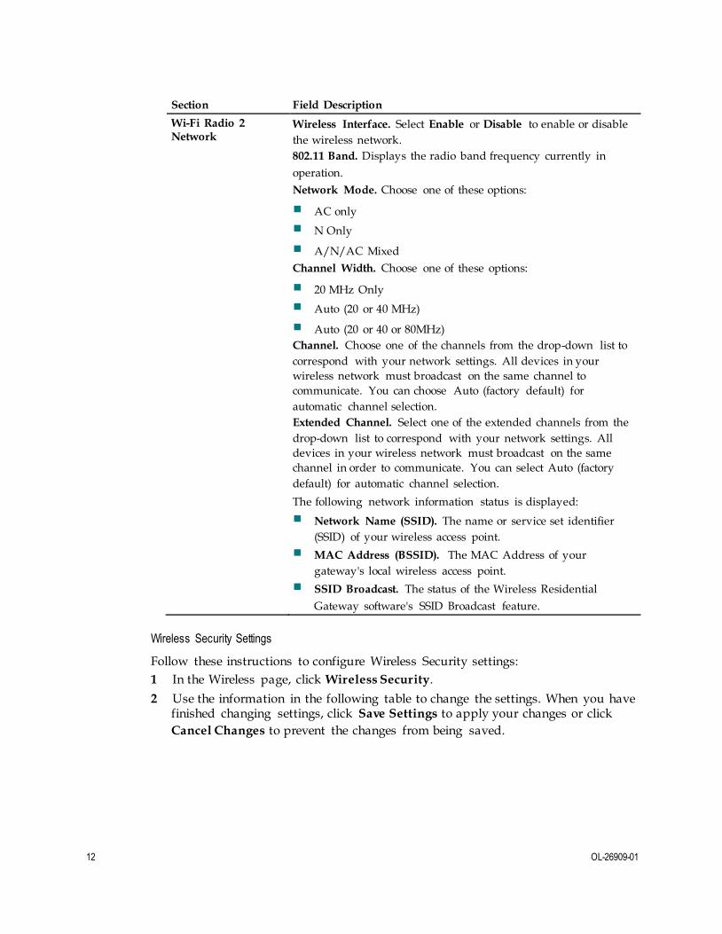
12 OL-26909-01
Section Field Description
Wi-Fi Radio 2 Network
Wireless Interface. Select Enable or Disable to enable or disable
the wireless network.
802.11 Band. Displays the radio band frequency currently in
operation.
Network Mode. Choose one of these options:
AC only
N Only
A/N/AC Mixed
Channel Width. Choose one of these options:
20 MHz Only
Auto (20 or 40 MHz)
Auto (20 or 40 or 80MHz)
Channel. Choose one of the channels from the drop-down list to
correspond with your network settings. All devices in your
wireless network must broadcast on the same channel to
communicate. You can choose Auto (factory default) for
automatic channel selection.
Extended Channel. Select one of the extended channels from the
drop-down list to correspond with your network settings. All
devices in your wireless network must broadcast on the same
channel in order to communicate. You can select Auto (factory
default) for automatic channel selection.
The following network information status is displayed:
Network Name (SSID). The name or service set identifier
(SSID) of your wireless access point.
MAC Address (BSSID). The MAC Address of your
gateway's local wireless access point.
SSID Broadcast. The status of the Wireless Residential
Gateway software's SSID Broadcast feature.
Wireless Security Settings
Follow these instructions to configure Wireless Security settings:
1 In the Wireless page, click Wireless Security.
2 Use the information in the following table to change the settings. When you have finished changing settings, click Save Settings to apply your changes or click
Cancel Changes to prevent the changes from being saved.

OL-26909-01 13
Section Field Description
Wi-Fi Radio 1 Security
Security Mode. Allows you to select a wireless security mode to
help protect your network. If you select Disable, then your
wireless network is not secure and any wireless device within
range may connect to it.
Note: The factory default mode is WPA or WPA2-Personal.
Encryption. Allows you to select a level of encryption based on
the wireless security mode that you choose.
Passphrase. The passphrase key for the Wireless Residential
Gateway software. The key can be from 8 to 63 characters. The
factory default passphrase is equal to the 9-digit serial number of
your Wireless Residential Gateway software. The serial number
can be found on the rating label attached to your wireless gateway. Selecting Show Key toggles the passphrase between
hidden characters and clear text.
Note: Your service provider may provide you with a wireless
configuration card that contains SSID and wireless security
configuration information for your home network that may differ
from what is described above
Key Renewal. Enter a Key Renewal period, which instructs the
device how often it should change encryption keys. The default is
3600 seconds.
Wi-Fi Radio 2
Security Security Mode. Allows you to select a wireless security mode to
help protect your network. If you select Disable, then your
wireless network is not secure and any wireless device within
range may connect to it.
Note: The factory default mode is WPA or WPA2-Personal.
Encryption. Allows you to select a level of encryption based on
the wireless security mode that you choose.
Passphrase. The passphrase key for the Wireless Residential
Gateway software. The key can be from 8 to 63 characters. The
factory default passphrase is equal to the 9-digit serial number of
your Wireless Residential Gateway software. The serial number
can be found on the rating label attached to your wireless gateway. Selecting Show Key toggles the passphrase between
hidden characters and clear text.
Note: Your service provider may provide you with a wireless
configuration card that contains SSID and wireless security
configuration information for your home network that may differ
from what is described above
Key Renewal. Enter a Key Renewal period, which instructs the
device how often it should change encryption keys. The default is
3600 seconds.
14 OL-26909-01
Configure MAC Filtering
Use the MAC Filter feature to either allow or block access to your wireless LAN
based on the MAC Address of the wireless client devices. The MAC Filter feature,
also known as an access list, can be used to help protect your wireless network from
access by unauthorized users.
Follow these instructions to configure MAC address filtering for your wireless
network:
1 In the Wireless page, click MAC Filter .
2 Use the information in the following table to change the settings. When you have finished changing the settings, click Save Settings to apply your changes or click
Cancel Changes to prevent the changes from being saved.
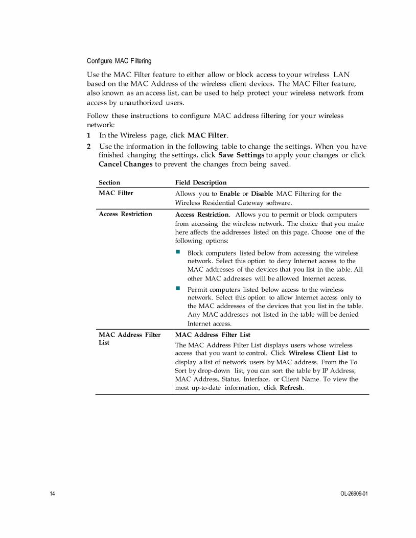
Section Field Description
MAC Filter Allows you to Enable or Disable MAC Filtering for the
Wireless Residential Gateway software.
Access Restriction Access Restriction. Allows you to permit or block computers
from accessing the wireless network. The choice that you make
here affects the addresses listed on this page. Choose one of the
following options:
Block computers listed below from accessing the wireless network. Select this option to deny Internet access to the
MAC addresses of the devices that you list in the table. All
other MAC addresses will be allowed Internet access.
Permit computers listed below access to the wireless network. Select this option to allow Internet access only to
the MAC addresses of the devices that you list in the table.
Any MAC addresses not listed in the table will be denied
Internet access.
MAC Address Filter List
MAC Address Filter List
The MAC Address Filter List displays users whose wireless access that you want to control. Click Wireless Client List to
display a list of network users by MAC address. From the To
Sort by drop-down list, you can sort the table by IP Address,
MAC Address, Status, Interface, or Client Name. To view the
most up-to-date information, click Refresh.

OL-26909-01 15
Configure Adv anced Settings
Advanced wireless settings add another layer of security to the wireless network for
the Wireless Residential Gateway software. Use this page to set up the following
advanced wireless functions:
N Transmission Rate
CTS Protection Mode
Beacon Interval
DTM Interval
Fragmentation Threshold
RTS Threshold
If you are an expert administrator, follow these instructions to adjust critical settings:
Important: Only an expert administrator should adjust these settings. Incorrect
settings can reduce wireless performance.
1 In the Wireless page, click Advanced Settings
2 Use the information in the following table to change the settings. When you have finished changing the settings, click Save Settings to apply your changes or click
Cancel Changes to prevent the changes from being saved.
Section Field Description
Wi-Fi Radio 1 Settings
and
Wi-Fi Radio 2
Settings
CTS Protection Mode. CTS (Clear-To-Send) Protection Mode
boosts the device's ability to catch all wireless transmissions, but
can severely decrease performance. Select Auto if you want the
device to use this feature as needed, when the Wireless-N/G
products are not able to transmit to the device in an
environment with heavy 802.11b traffic. Select Disable if you
want to permanently disable this feature.
Beacon Interval. The Beacon Interval value indicates the
frequency interval of the beacon. A beacon is a packet broadcast
by the device to synchronize the wireless network.
(Default: 100 msec, Range: 20-1000)

16 OL-26909-01
DTIM Interval. The Delivery Traffic Indication Message
(DTIM) indicates the interval between Broadcasts/Multicast
transmissions. DTIM field is a countdown field informing
clients of the next window for listening to broadcast and
multicast messages. When the device has buffered broadcast or
multicast messages for associated clients, it sends the next
DTIM with a DTIM Interval value. Its clients hear the beacons
and awaken to receive the broadcast and multicast messages.
(Default: 1, Range: 1-255)
Fragmentation Threshold. The fragmentation threshold value
specifies the maximum size for a packet before data is
fragmented into multiple packets. If you experience a high
packet error rate, you may slightly increase the Fragmentation
Threshold. Setting the Fragmentation Threshold too low may
result in poor network performance. Only minor reduction of the default value is recommended. In most cases, it should
remain at its default value of 2346.
RTS Threshold. The RTS Threshold determines at what packet
size beyond which the ready to send/clear to send (RTS/CTS)
mechanism is invoked. Should you encounter inconsistent data
flow, only minor reduction of the default value, 2346, is
recommended. If a network packet is smaller than the preset
RTS Threshold size, the RTS/CTS mechanism will not be
enabled. The device sends Request to Send (RTS) frames to a
particular receiving station and negotiates the sending of a data
frame. After receiving an RTS, the wireless station responds
with a Clear to Send (CTS) frame to acknowledge the right to
begin transmission. The RTS Threshold value should remain at
its default value of 2347.
OL-26909-01 17
Configure WDS Settings
The Wireless Distribution System (WDS) Settings page allows you to expand the
coverage of your wireless network by deploying signal repeaters.
Follow these instructions to configure Reporting settings:
Important: Make sure the channel settings are the same for all WDS enabled devices.
1 In the Wireless page, click WDS Settings.
2 Use the information in the following table to change the settings. When you have finished changing the settings, click Save Settings to apply your changes or click
Cancel Changes to prevent the changes from being saved.
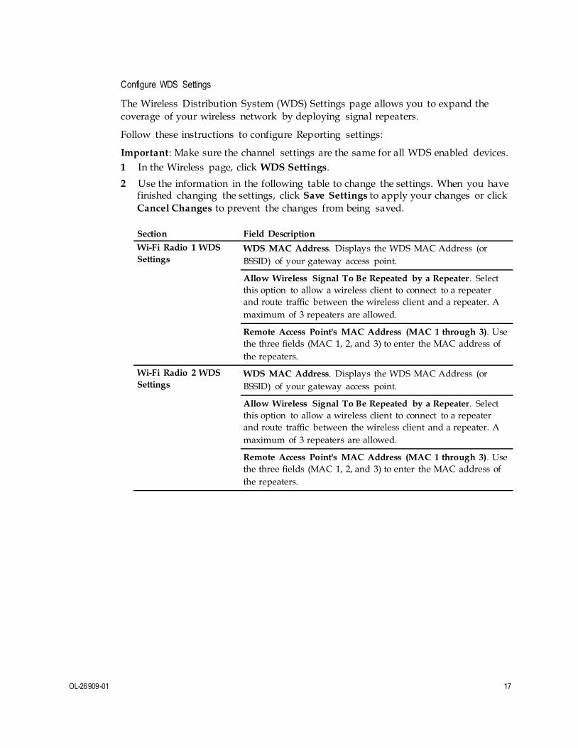
Section Field Description
Wi-Fi Radio 1 WDS
Settings WDS MAC Address. Displays the WDS MAC Address (or
BSSID) of your gateway access point.
Allow Wireless Signal To Be Repeated by a Repeater. Select
this option to allow a wireless client to connect to a repeater
and route traffic between the wireless client and a repeater. A
maximum of 3 repeaters are allowed.
Remote Access Point's MAC Address (MAC 1 through 3). Use
the three fields (MAC 1, 2, and 3) to enter the MAC address of
the repeaters.
Wi-Fi Radio 2 WDS
Settings WDS MAC Address. Displays the WDS MAC Address (or
BSSID) of your gateway access point.
Allow Wireless Signal To Be Repeated by a Repeater. Select
this option to allow a wireless client to connect to a repeater
and route traffic between the wireless client and a repeater. A
maximum of 3 repeaters are allowed.
Remote Access Point's MAC Address (MAC 1 through 3). Use
the three fields (MAC 1, 2, and 3) to enter the MAC address of
the repeaters.

18 OL-26909-01
Configure QoS Settings
Quality of Service (QoS) ensures better service to high-priority types of network
traffic, which may involve demanding, real-time applications, such as video
conferencing. QoS settings allow you to specify priorities for different types of
traffic. Lower priority traffic will be slowed down to allow greater throughput or
less delay for high priority traffic.
Follow these instructions to configure QoS priorities for different types of traffic:
1 In the Wireless page, click the QoS tab.
2 Use the information in the following table to change the settings. When you have finished changing the settings, click Save Settings to apply your changes or click
Cancel Changes to prevent the changes from being saved.
Section Field Description
Wi-Fi Radio 1 QoS
and
Wi-Fi Radio 2 QoS
WMM Support. If WMM (Wi-Fi Multimedia) is supported
by your wireless clients, enabling this feature means that
voice and multimedia traffic will be given higher priority
than other traffic.
Select the desired option:
Enable (factory default)
Disable
No ACK. Allows you to enable or disable No ACK. No ACK is
disabled by default. This feature is recommended for data
services where speed of transmission is important and packet loss is tolerable to a certain degree. If you select Disable, an
acknowledge packet is returned for every packet received. This
provides a more reliable transmission, but it increases traffic
load, which decreases performance.
Select the desired option:
Enable
Disable (factory default)

OL-26909-01 19
Configure Security
This section provides procedures for configuring the following settings that are
available as tabs in the Security page.
Configure Firewall Settings
Use the settings on this page to configure a firewall and filter out various types of
unwanted traffic on the Wireless Residential Gateway software local network.
Advanced firewall technology deters hackers and protects the home network from
unauthorized access.
Follow these instructions to configure Firewall settings:
1 In the Security page, click Firewall.
2 Use the information in the following table to change the settings. When you have finished changing the settings, click Save Settings to apply your changes or click
Cancel Changes to prevent the changes from being saved.
Section Field Description
Firewall SPI Firewall Protection. Blocks Denial of Service (DoS) attacks.
A DoS attack does not attempt to steal data or damage your
computers, but it overloads your Internet connection so that
you cannot use it.
Select the desired option:
Off (factory default)
On
IPv6 Firewall Protection. Blocks Denial of Service (DoS)
attacks for the IPv6 network. A DoS attack does not attempt to
steal data or damage your computers, but it overloads your
Internet connection so that you cannot use it.
Select the desired option:
Off
On (factory default)
Filters Block fragmented IP packets. Enables/disables filtering of
fragmented IP packets. This feature helps protect your private
local network from Internet based denial of service attacks.
Block Port Scan Detection. Enables/disables the gateway from
responding to Internet based port scans. This feature is
designed to protect your private local network from Internet
based hackers who attempt to gain unsolicited access your
network by detecting open IP ports.
Block IP Flood Detection. Blocks malicious devices that are
attempting to flood devices or networks with illegal broadcast
packets. Also referred to as "broadcast storm."
Note: This is the factory default option.
20 OL-26909-01
Section Field Description
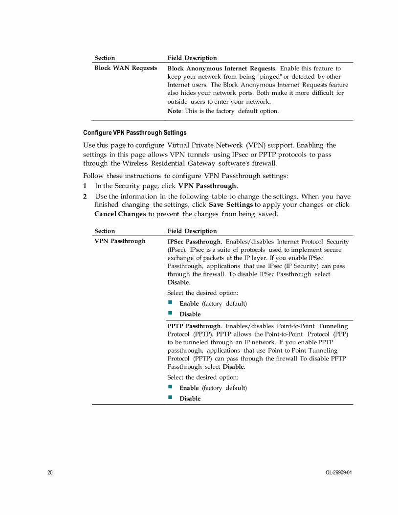
Block WAN Requests Block Anonymous Internet Requests. Enable this feature to
keep your network from being "pinged" or detected by other
Internet users. The Block Anonymous Internet Requests feature
also hides your network ports. Both make it more difficult for
outside users to enter your network.
Note: This is the factory default option.
Configure VPN Passthrough Settings
Use this page to configure Virtual Private Network (VPN) support. Enabling the
settings in this page allows VPN tunnels using IPsec or PPTP protocols to pass
through the Wireless Residential Gateway software's firewall.
Follow these instructions to configure VPN Passthrough settings:
1 In the Security page, click VPN Passthrough.
2 Use the information in the following table to change the settings. When you have finished changing the settings, click Save Settings to apply your changes or click
Cancel Changes to prevent the changes from being saved.
Section Field Description
VPN Passthrough IPSec Passthrough. Enables/disables Internet Protocol Security
(IPsec). IPsec is a suite of protocols used to implement secure
exchange of packets at the IP layer. If you enable IPSec
Passthrough, applications that use IPsec (IP Security) can pass
through the firewall. To disable IPSec Passthrough select
Disable.
Select the desired option:
Enable (factory default)
Disable
PPTP Passthrough. Enables/disables Point-to-Point Tunneling
Protocol (PPTP). PPTP allows the Point-to-Point Protocol (PPP)
to be tunneled through an IP network. If you enable PPTP
passthrough, applications that use Point to Point Tunneling
Protocol (PPTP) can pass through the firewall To disable PPTP
Passthrough select Disable.
Select the desired option:
Enable (factory default)
Disable
OL-26909-01 21
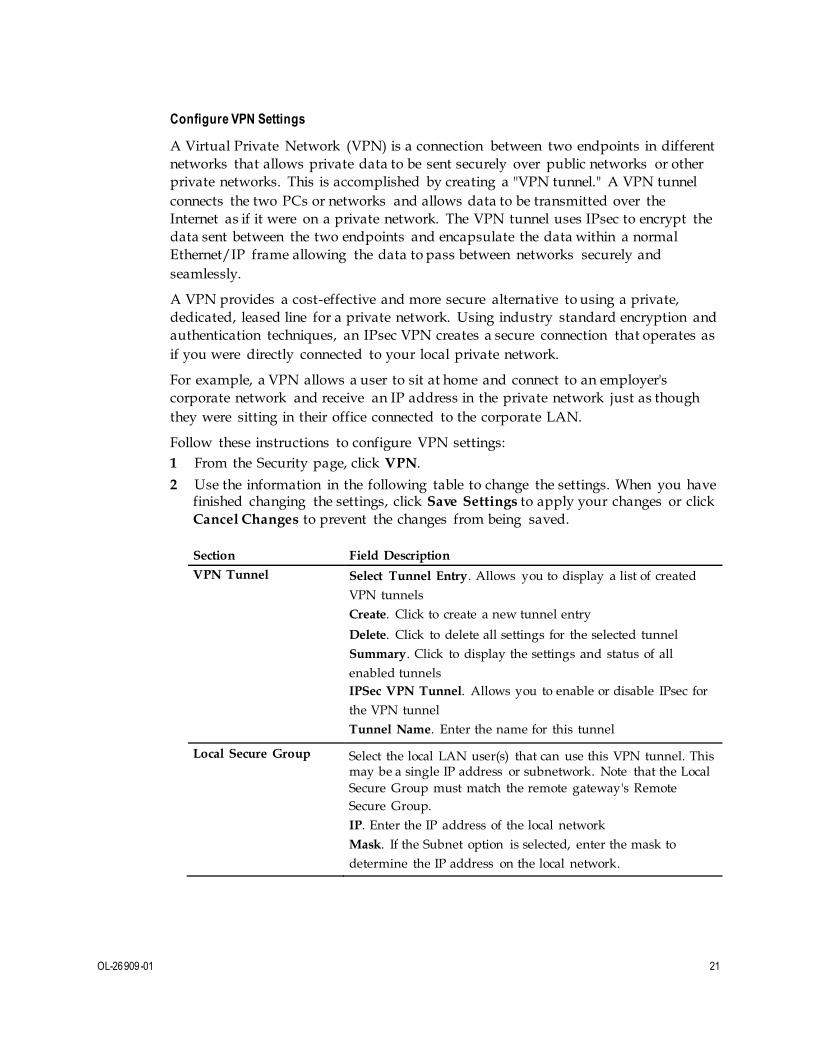
Configure VPN Settings
A Virtual Private Network (VPN) is a connection between two endpoints in different
networks that allows private data to be sent securely over public networks or other
private networks. This is accomplished by creating a "VPN tunnel." A VPN tunnel
connects the two PCs or networks and allows data to be transmitted over the
Internet as if it were on a private network. The VPN tunnel uses IPsec to encrypt the
data sent between the two endpoints and encapsulate the data within a normal
Ethernet/IP frame allowing the data to pass between networks securely and
seamlessly.
A VPN provides a cost-effective and more secure alternative to using a private,
dedicated, leased line for a private network. Using industry standard encryption and
authentication techniques, an IPsec VPN creates a secure connection that operates as
if you were directly connected to your local private network.
For example, a VPN allows a user to sit at home and connect to an employer's
corporate network and receive an IP address in the private network just as though
they were sitting in their office connected to the corporate LAN.
Follow these instructions to configure VPN settings:
1 From the Security page, click VPN.
2 Use the information in the following table to change the settings. When you have finished changing the settings, click Save Settings to apply your changes or click
Cancel Changes to prevent the changes from being saved.
Section Field Description
VPN Tunnel Select Tunnel Entry. Allows you to display a list of created
VPN tunnels
Create. Click to create a new tunnel entry
Delete. Click to delete all settings for the selected tunnel
Summary. Click to display the settings and status of all
enabled tunnels
IPSec VPN Tunnel. Allows you to enable or disable IPsec for
the VPN tunnel
Tunnel Name. Enter the name for this tunnel
Local Secure Group Select the local LAN user(s) that can use this VPN tunnel. This may be a single IP address or subnetwork. Note that the Local
Secure Group must match the remote gateway's Remote
Secure Group.
IP. Enter the IP address of the local network
Mask. If the Subnet option is selected, enter the mask to
determine the IP address on the local network.

22 OL-26909-01
Section Field Description
Remote Secure Group Select the remote LAN user(s) behind the remote gateway who can use this VPN tunnel. This may be a single IP address,
a sub-network, or any addresses. If "Any" is set, the Wireless
Residential Gateway software acts as responder and accepts
requests from any remote user. Note that the Remote Secure
Group must match the remote gateway's Local Secure Group.
IP. Enter the IP address of the remote network
Mask. If the Subnet option is selected, enter the mask to
determine the IP addresses on the remote network
Remote Secure Gateway
Select the desired option, IP Addr., Any, or FQDN. If the Wireless Residential Gateway software has a dynamic IP
address, select Any or FQDN. If Any is selected, then the
Wireless Residential Gateway software will accept requests
from any IP address.
FQDN. If FQDN is selected, enter the domain name of the
remote gateway, so the Wireless Residential Gateway
software can locate a current IP address using DDNS.
IP. The IP address in this field must match the public (WAN
or Internet) IP address of the remote gateway at the other end
of this tunnel.
Key Management Key Exchange Method. The Wireless Residential Gateway
software supports both automatic and manual key
management. Note that both sides must use the same key
management method.
Select one of the following options for the key exchange
method:
Auto (IKE). Uses Internet Key Exchange (IKE) protocols
to negotiate key material for Security Association (SA). Configure Auto key management using the following
settings:
– Encryption: The Encryption method determines the
length of the key used to encrypt/decrypt ESP packets.
Notice that both sides must use the same method.
– Authentication: The Authentication method
authenticates the Encapsulating Security Payload (ESP) packets. Select MD5 or SHA. Notice that both sides
(VPN endpoints) must use the same method.
MD5: A one-way hashing algorithm that
produces a 128-bit digest
SHA: A one-way hashing algorithm that produces
a 160-bit digest

OL-26909-01 23
Section Field Description
– Perfect Forward Secrecy (PFS): If PFS is enabled, IKE
Phase 2 negotiation will generate new key material for
IP traffic encryption and authentication. Note that both
sides must have PFS enabled.
– Pre-Shared Key: IKE uses the Preshared key to
authenticate the remote IKE peer. Both character and
hexadecimal values are acceptable in this field. (For
example, "My_@123" or "0x4d795f40313233" are
acceptable.) Note that both sides must use the same
Preshared key.
– Key Lifetime: This field specifies the lifetime of the
IKE generated key. If the time expires, a new key will
be renegotiated automatically. The Key Lifetime may
range from 300 to 100,000,000 seconds. The default
lifetime is 3600 seconds.
Status This field shows the connection status for the selected tunnel. The state is either Connected or Not Connected.
Buttons Connect. Click to establish a connection for the current VPN tunnel. If you have made any changes, click Save Settings to
first apply your changes.
Disconnect. Click to break a connection for the current VPN
tunnel.
View Log. Click to view the VPN log, which shows details of
each established tunnel.
Advanced Settings. If the Key Exchange Method is Auto
(IKE), this button provides access to additional settings
relating to IKE. Click this button if the gateway is unable to
establish a VPN tunnel to the remote gateway, and make sure
the Advanced Settings match those on the remote gateway.
Phase 1 - Operation Mode. Select the method appropriate
for the remote VPN endpoint.
– Main: Main mode is slower but more secure.
– Aggressive: Aggressive mode is faster but less secure.
Local Identity. Select the desired option to match the
Remote Identity setting at the other end of this tunnel.
– Local IP Address: Your WAN (Internet) IP address
– Name: Your domain name
Remote Identity. Select the desired option to match the
Local Identity setting at the other end of this tunnel.
– Local IP Address: WAN (Internet) IP address of the
remote VPN endpoint
– Name: Domain name of the remote VPN endpoint
Encryption. This is the encryption algorithm used for the
IKE SA. It must match the setting used at the other end of
the tunnel.
24 OL-26909-01
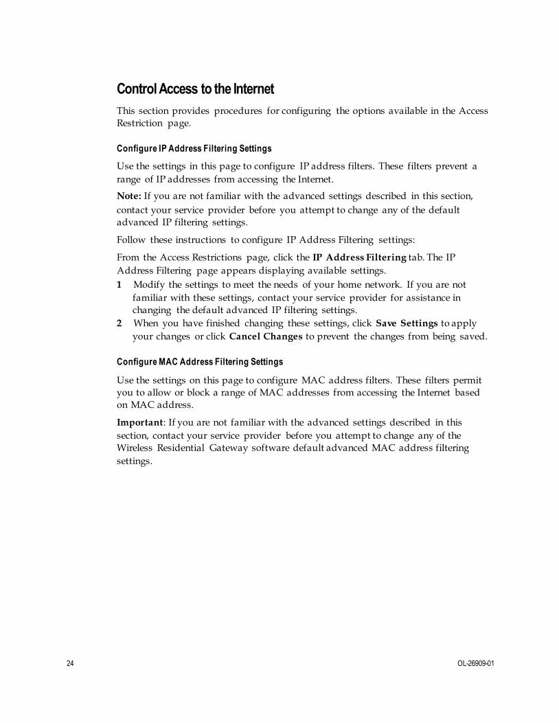
Control Access to the Internet
This section provides procedures for configuring the options available in the Access
Restriction page.
Configure IP Address Filtering Settings
Use the settings in this page to configure IP address filters. These filters prevent a
range of IP addresses from accessing the Internet.
Note: If you are not familiar with the advanced settings described in this section,
contact your service provider before you attempt to change any of the default
advanced IP filtering settings.
Follow these instructions to configure IP Address Filtering settings:
From the Access Restrictions page, click the IP Address Filtering tab. The IP
Address Filtering page appears displaying available settings.
1 Modify the settings to meet the needs of your home network. If you are not
familiar with these settings, contact your service provider for assistance in
changing the default advanced IP filtering settings.
2 When you have finished changing these settings, click Save Settings to apply
your changes or click Cancel Changes to prevent the changes from being saved.
Configure MAC Address Filtering Settings
Use the settings on this page to configure MAC address filters. These filters permit
you to allow or block a range of MAC addresses from accessing the Internet based
on MAC address.
Important: If you are not familiar with the advanced settings described in this
section, contact your service provider before you attempt to change any of the
Wireless Residential Gateway software default advanced MAC address filtering
settings.

OL-26909-01 25
Follow these instructions to configure MAC Address Filtering settings:
1 In the Access Restrictions page, click MAC Address Filtering.
2 Use the information in the following table to change the settings. When you have finished changing the settings, click Save Settings to apply your changes or click
Cancel Changes to prevent the changes from being saved.
Field Name Description
Access
Restriction
Block devices listed below from accessing the Internet.
Select to deny Internet access to the MAC addresses listed in
the MAC Address Filter List fields. All other MAC addresses
will be allowed Internet access.
Permit devices listed below to access the Internet. Select to
allow Internet access only to the MAC addresses of the
devices you list in the MAC Address Filter fields. Any MAC
addresses not listed in the table will be denied Internet access.
MAC Address Filter List
In the available fields, enter the MAC addresses of the
devices whose Internet access you want to control.
Configure Basic Rules Settings
Use the settings on this page to block or allow specific kinds of Internet usage and
traffic, such as Internet access, designated applications, websites, and inbound traffic
during specific days and times. The Access Restrictions Basic Rules page allows you
to configure parental controls on the Wireless Residential Gateway software, and to
monitor the individuals who are authorized to set parental controls.
Use the settings on this page to block or allow specific kinds of Internet usage and
traffic, configure parental controls, and monitor individuals who are authorized to
set parental controls.
Follow these instructions to configure Basic Rules settings:
1 In the Access Restrictions page, Basic Rules.
2 Use the information in the following table to change the settings. When you have
finished changing the settings, click Save Settings to apply your changes or click
Cancel Changes to prevent the changes from being saved.
Section Field Description
Parental Control Basic
Setup Parental Control Activation. Enable or disable parental controls. To enable parental controls, check the Enable Parental
Control check box and click Apply. To disable parental
controls, uncheck the Enable Parental Control check box and
click Apply.
Add Rule. Adds and saves a new Rule to the list of content
rules.
Remove Rule. Removes the selected rule from the content rule
list.

26 OL-26909-01
Section Field Description
Keyword List Keyword List. Allows you to create a list of keywords. Any
attempt to access a URL that contains any of the keywords in
this list will be blocked by the Wireless Residential Gateway
software.
Add/Remove Keyword. Allows you to add new keywords to
the list or to delete selected keywords from the list.
Blocked Domain List Blocked Domain List. Allows you to create a list of domains
that the Wireless Residential Gateway software should block
access to. Any attempt to access any of the Domains in this list
will be blocked by the Wireless Residential Gateway software.
Add/Remove Domain. Add new domains to the list or delete
selected domains from the list.
Allowed Domain List Allowed Domain List. Create a list of domains to which the
Wireless Residential Gateway software allows access.
Add/Remove Allowed Domain. Add new domains to the list
or delete selected domains from the list.
Parental Control
Bypass List Parental Control Bypass List. Devices in this list bypass
parental control settings.
Add/Remove MAC Address. Allows you to add or remove
new devices, by device MAC address to the Parental Control
Bypass list.
Override the Password Password. Create a password to temporarily override user-
access restrictions to a blocked Internet site.
Re-Enter Password. Re-enter the same password for
confirmation of the override password in the previous field.
Access Duration. Designate an amount of time in minutes that
the Override password will allow temporary access to a
restricted Internet site.
Apply. Saves all additions, edits, and changes.
To use key w ord and domain blocking
Keyword and domain blocking allows you to restrict access to Internet sites by
blocking access to those sites based on a word or a text string contained in the URLs
used to access those Internet sites.
Domain blocking allows you to restrict access to websites based on the site's domain
name. The domain name is the portion of the URL that precedes the familiar .com,
.org, or .gov extension.
Keyword blocking allows you to block access to Internet sites based on a keyword or
text string being present anywhere in the URL, not just in the domain name.
Note: The domain blocking feature blocks access to any domain in the Domain list. It
will also block domains, any portion of which contains an exact match to entries in
the list.

OL-26909-01 27
For example, if you enter example.com as a domain, any site that contains
"example.com" will be blocked. Generally, you do not want to include "www." in a
domain name because doing so limits the blocking to only the site that matches that
domain name exactly. For instance, if you enter www.example.com into the list, only
the one site that matches that name exactly will be blocked. Consequently, if you do
not include the "www.," then all sites within and associated with "example.com" will
be blocked.
Block Access to Websites
If you wish to block access to websites, use the Blocked Domain List or the Keyword List.
To use the Blocked Domain List, enter the URLs or domain names of the websites
that you wish to block.
Use the Keyword List to enter the keywords that you wish to block. If any of these
keywords appears in the URL of a website, access to the site will be blocked. Note
that only the URL is checked, not the content of each website.
Configure Time of Day Rules Settings
Use the settings on this page to configure web access filters to block all Internet
traffic to and from specific network devices based on day of week and time of day
settings that you select.
Important: The Wireless Residential Gateway software uses the network time of day
clock that is managed by your data service provider. The time of day clock must be
accurate and represent the time of day in your time zone for this feature to operate
properly. Verify that the Status and Set Time pages reflect the correct time of day. If
they do not reflect the correct time of day, contact your data service provider. You
can also adjust your settings to account for the difference.
Follow these instructions to configure Time of Day Rules settings:
1 In the Access Restrictions page, click Time of Day Rules.
2 Use the information in the following table to change the settings. When you have finished changing the settings, click Save Settings to apply your changes or click
Cancel Changes to prevent the changes from being saved.
Section Field Description
Tod Filter Add. Add a new Time of Day access filter or rule. Enter the name of the filter and click the Add key to add the filter to the list. Time of
Day rules are used to restrict Internet access based on the day and
time.
Remove. Remove the selected filter from the Time of Day filter list.
Days to Block. Control access based on days of the week.
Schedule Time to Block. Control access based on the time of day.

28 OL-26909-01
Configure User Setup Settings
Use the settings in this page to set up additional accounts and user profiles for
household members. Each profile can be assigned customized levels of Internet
access as defined by the access rules assigned to that user's profile.
Important: These additional accounts do not grant administrative access to the
Wireless Residential Gateway software.
Once you define and enable user profiles, each user must sign-on each time they
wish to access the Internet. The user can sign-on when the pop-up dialog box
appears in their web browser. The user must enter their correct user name and
password to gain Internet access.
Follow these instructions to configure User Setup settings:
1 In the Access Restrictions page, click User Setup.
2 Use the information in the following table to change the settings. When you have
finished changing the settings, click Save Settings to apply your changes or click
Cancel Changes to prevent the changes from being saved.
Section Field Description
User Configure Add User. Add a new user profile. Enter the name of the user
and click Add User to add the user to the list.
User Settings. Allows you to edit a user profile by using the
drop-down list to edit a user profile. The drop-down list allows
you to recall the profile to be edited. User names and passwords
are case-sensitive.
Make sure to check the Enable box to activate the user profile. If
a profile is not active, that user will not be able to access the
Internet.
To remove a user profile, choose the profile from the drop-down
list and click Remove User.
Password. Enter the selected user's password in this field. All
users must enter their User Names and Passwords each time
they use the Internet. User names and passwords are case-
sensitive.
Note: The Wireless Residential Gateway software will allow
each user access to the Internet, subject to the rules selected in
this page for that user.
Re-Enter Password. Re-enter the same password for
confirmation of the password in the previous field.

OL-26909-01 29
Section Field Description
User Configure,
continued
Trusted User. Check this check box if the currently selected user
is to be designated a trusted user. Trusted users are not subject
to Internet access rules.
Content Rule. Select the Content Rule for the current user
profile. Content Rules must first be defined by going to the
Rules Configuration page. You can access the Rule
Configuration page by clicking the "Basic Rules" tab in this page.
For more information, go to Configure Basic Rules Settings (on
page 25).
Time Access Rule. Select the Time Access Rule for the current
user profile. Time Access Rules must first be defined by going to
the Time of Day Rules page. You can access the Time of Day
Rules page by clicking the “Time of Day Rules” tab in this page.
Session Duration. Enter the amount of time in minutes that the
user will be granted Internet access beginning at the time they sign on using their User Name and Password. The default
(factory) setting is 1440 minutes when a user is created;
otherwise, it is 0 (zero).
Note: Set the Session Duration to 0 (zero) to prevent session
timeout.
Inactivity Time. Enter the amount of time during a user session
where there is no Internet access activity, indicating that the
user is no longer online. If the inactivity timer is triggered, the
user session will be closed automatically. In To regain Internet
access, the user must log in again with their user name and
password. The default (factory) setting is 60 minutes when a
user is created; otherwise, it is 0 (zero).
Note: Set the Inactivity time value to 0 (zero) to prevent session
timeout.

30 OL-26909-01
Configure Local Log Settings
Use the settings in this page to track, by user, any attempts the user has made to
access Internet sites that are restricted. In this page, you can also view events
captured by the parental control event-reporting feature.
Follow these instructions to configure Local Log settings:
1 In the Access Restrictions page, click Local Log.
2 Use the information in the following table to change the settings. When you have
finished changing the settings, click Save Settings to apply your changes or click
Cancel Changes to prevent the changes from being saved.
Section Field Description
Local Log
Parental Control - Event Log
Last Occurrence. Displays the time of the most recent
attempt to access a restricted Internet site
Action. Displays the action taken by the system
Target. Displays the URL of the restricted site
User. Displays the user who attempted a restricted site
Source. Displays the IP address of the PC that was used
when attempting to access a restricted website
OL-26909-01 31
Configure Applications and Gaming
This section provides procedures for configuring the options in the Applications &
Gaming page.
Important: Most well-known Internet applications are supported by Application
Layer Gateways (ALGs). ALGs automatically adjust the gateway firewall to allow
data to pass without making any custom settings. We recommend that you test your
application before making changes in this section.
Configure Port Filtering Settings
Use the settings in this window to configure Transmission Control Protocol (TCP)
and User Datagram Protocol (UDP) port filters. These filters prevent a range of
TCP/UDP ports from accessing the Internet. You can also prevent PCs from sending
outgoing TCP/UDP traffic to the WAN on specific IP port numbers. This filter is not
IP address- or MAC address- specific. The system blocks the specified port ranges
for all PCs.
Follow these instructions to configure the port filtering for applications and gaming
features:
1 In the Applications & Gaming page, click Port Filtering.
2 Use the information in the following table to change the settings. When you have
finished changing the settings, click Save Settings to apply your changes or click
Cancel Changes to prevent the changes from being saved.
Section Field Description
Port Filtering Start Port. This is the beginning of the port range. Enter the
beginning of the range of port numbers (external ports) used by the
server or Internet application. Check with the software
documentation of the Internet application for more information if
necessary.
End Port. This is the end of the port range. Enter the end of the
range of port numbers (external ports) used by the server or Internet
application. Check with the software documentation of the Internet
application for more information if necessary.
Protocol. Select one of the following protocols:
TCP
UDP
Both
Enable. Allows you to enable port filtering.

32 OL-26909-01
Configure Port Range Forwarding Settings
The settings on this page allow you to configure the ports that are to be used for
public services on your network, such as web servers, FTP servers, email servers or
other specialized Internet applications.
Important:
The Wireless Residential Gateway software normally implements a feature called
Port Translation. Port Translation monitors what ports are actually being used by
your PCs or other devices on your LAN. This monitoring provides an added
level of security beyond what the firewall provides. However, there are some
applications that require the Wireless Residential Gateway software to use
specific ports to connect over the Internet.
Port Range Forwarding continually exposes the selected ports to the public
Internet. This means that the firewall is no longer active on these ports. The
device with the forwarding IP address can be exposed to hacker attacks while the
port range is being forwarded.
Follow these instructions to configure port range forwarding settings:
1 In the Applications & Gaming page, click Port Range Forwarding.
2 Use the information in the following table to change the settings. When you have
finished changing the settings, click Save Settings to apply your changes or click
Cancel Changes to prevent the changes from being saved.
Section Field Description
Port Range Forwarding External Start. For the Start port, select a port from the
recommended 49152 - 65535 range. Keep in mind that ports
used are program specific so check which ones the program
requires to be forwarded.
External End. For the End port, select a port from the
recommended 49152 - 65535 range. Keep in mind that ports
used are program specific so check which ones the program
requires to be forwarded.
Internal IP Address. Enter the computer’s IP address to which
this is to apply.
Internal Start Port. This is the beginning of the port
range. Enter the beginning of the range of port numbers
(internal ports) used by the server or Internet application.
Check with the software documentation of the Internet
application for more information if necessary.
Internal End Port. This is the end of the port range. Enter the
end of the range of port numbers (internal ports) used by the
server or Internet application. Check with the software
documentation of the Internet application for more information
if necessary.

OL-26909-01 33
Section Field Description
Protocol. Select one of the following protocols:
TCP
UDP
Both
Enable. Check this check box to enable port forwarding for the
specified ports and IP addresses.
Configure Port Range Triggering Settings
Port range triggering is a way to dynamically forward ports to a LAN PC that needs
them at a particular time. That particular time is when it runs a certain application
that performs some event that triggers the router. This event must be an outbound
access of a particular port range.
Follow these instructions to configure port range triggering:
1 In the Applications & Gaming page, click Port Range Triggering.
2 Use the information in the following table to change the settings. When you have
finished changing the settings, click Save Settings to apply your changes or click
Cancel Changes to prevent the changes from being saved.
Section Field Description
Port Range Triggering
Triggered Range Start Port. For the Start port, select a port from the
recommended 49152 - 65535 range. Keep in mind that ports
used are program specific so check which ones the program
requires to be forwarded.
End Port. For the End port, select a port from the
recommended 49152 - 65535 range. Keep in mind that ports
used are program specific so check which ones the program
requires to be forwarded.
Forwarded Range Start Port. For the Start port, select a port from the
recommended 49152 - 65535 range. Keep in mind that ports
used are program specific so check which ones the program
requires to be forwarded.
End Port. For the End port, select a port from the
recommended 49152 - 65535 range. Keep in mind that ports
used are program specific so check which ones the program
requires to be forwarded.
Protocol. Select one of the following protocols:
TCP
UDP
Both
34 OL-26909-01
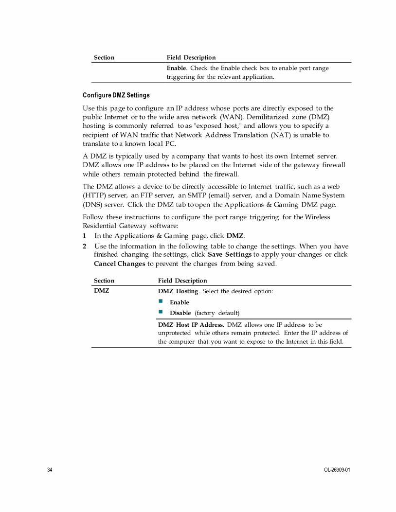
Section Field Description
Enable. Check the Enable check box to enable port range
triggering for the relevant application.
Configure DMZ Settings
Use this page to configure an IP address whose ports are directly exposed to the
public Internet or to the wide area network (WAN). Demilitarized zone (DMZ)
hosting is commonly referred to as "exposed host," and allows you to specify a
recipient of WAN traffic that Network Address Translation (NAT) is unable to
translate to a known local PC.
A DMZ is typically used by a company that wants to host its own Internet server.
DMZ allows one IP address to be placed on the Internet side of the gateway firewall
while others remain protected behind the firewall.
The DMZ allows a device to be directly accessible to Internet traffic, such as a web
(HTTP) server, an FTP server, an SMTP (email) server, and a Domain Name System
(DNS) server. Click the DMZ tab to open the Applications & Gaming DMZ page.
Follow these instructions to configure the port range triggering for the Wireless
Residential Gateway software:
1 In the Applications & Gaming page, click DMZ.
2 Use the information in the following table to change the settings. When you have finished changing the settings, click Save Settings to apply your changes or click
Cancel Changes to prevent the changes from being saved.
Section Field Description
DMZ DMZ Hosting. Select the desired option:
Enable
Disable (factory default)
DMZ Host IP Address. DMZ allows one IP address to be
unprotected while others remain protected. Enter the IP address of
the computer that you want to expose to the Internet in this field.

OL-26909-01 35
Configure Administration Settings
This section provides procedures for configuring the options available on the
Administration page.
Configure Management Settings
Use the settings in the Administration Management page to a llow the administrator
to manage specific functions for access and security.
Follow these instructions to configure Administration Management settings:
1 In the Administration page, click Management.
2 Use the information in the following table to change the remaining settings. When you have finished changing the settings, click Save Settings to apply your
changes or click Cancel Changes to prevent the changes from being saved.
Field Description
Gateway Setup (WAN)
Connection Mode. This setting allows you to determine how the
WAN (or gateway interface to the Internet) obtains its IP address.
Internet Connection Type
DHCP (factory default). Allows the gateway to obtain a public IP
address automatically.
Static IP. Allows you to specify the WAN IP address and
corresponding server information as static or fixed values that will
be used whenever the gateway goes online.
Internet IP Address. Enter the gateway’s IP address (as seen from
the Internet).
Subnet Mask. Enter the gateway’s subnet mask (as seen from the
Internet, including your service provider).
Default Gateway. Enter the default gateway of the service
provider’s server.
Primary DNS. Enter the primary domain name server IP
address(es) provided by your service provider. This is required.
Secondary DNS. Enter the secondary domain name server IP
address(es) provided by your service provider. This is optional.
MTU MTU size. MTU is the maximum transmission unit. The MTU size
specifies the largest packet size permitted for Internet transmission. Choose Manual if you want to manually enter the largest packet
size that will be transmitted. The recommended size is 1500 MTU.
You should leave this value in the 1200 to 1500 range to have the
device select the best MTU for your Internet connection. The
factory default is 0 (automatic)

36 OL-26909-01
Field Description
Gateway Access
Local Access
Current User Name. Identifies the currently logged in user.
Change Current User Name to. This field allows you to change
your user name. If you want to change your user name, enter your new user name in this field and click Save Settings to apply the
change.
Note: The factory default user name is a blank field.
Change Password to. This field allows you to change your
password. If you want to change your password, enter your new password in this field. Then, re-enter your new password in the Re-
Enter New Password field and click Save Settings to apply the
change.
Note: The factory default password is a blank field.
Re-Enter New Password. Allows you to re-enter the new
password. You must enter the same password as the one entered in the previous field Change Password to. After you re-enter your
new password, click Save Settings to apply the change.
Remote Access Remote Management. Allows you to enable or disable remote
management. This feature allows you to access and manage your
gateway settings from the Internet when you are away from home. To allow remote access, select Enable. Otherwise, keep the default setting as Disable. The protocol HTTP is required for remote
management. To remotely access the device, enter https://xxx.xxx.xxx.xxx:8080 in your web browser's Address field
(the x's represent the device's Internet IP address, and 8080
represents the specified port).
Management Port. Enter the port number that will be open to
outside access. The default setting is 8080. This port must be used
when you establish a remote connection.
UPnP UPnP. Universal Plug and Play (UPnP) allows Windows XP and
Vista to automatically configure the gateway for various Internet
applications, such as gaming and videoconferencing. If you want to
use UPnP, keep the default, Enable. Otherwise, select Disable.
IGMP IGMP Proxy. Internet Group Multicast Protocol (IGMP) is used to
establish membership in a multicast group and is commonly used
for multicast streaming applications. For example, you may have
Internet Protocol Television (IPTV) with multiple set-tops on the
same local network. These set-tops have different video streams
running simultaneously, so you should use the IGMP feature of the
router.
IGMP forwarding (proxying) is a system that improves
multicasting for LAN-side clients. If the clients support this option,
keep the default, Enable. Otherwise, select Disable.

OL-26909-01 37
Configuring Reporting Settings
Follow these instructions to configure Reporting settings:
1 In the Administration page, click Reporting.
2 Use the information in the following table to change the settings. When you have
finished changing the settings, click Save Settings to apply your changes or click
Cancel Changes to prevent the changes from being saved.
Section Field Description
Reporting Email Alerts. If enabled, an email will be sent immediately if a Denial
of Service (DoS) attack is detected. To use this feature, provide the
necessary email address information.
SMTP Mail Server. Enter the address (domain name) or IP address of
the Simple Mail Transport Protocol (SMTP) server you use for outgoing
email.
E-Mail Address for Alert Logs. Enter the email address that should
receive the logs.
SMTP Username. Enter the username for the SMTP server.
SMTP Password. Enter the password for the SMTP server.
View Log. Click to display log data.
Configure Diagnostics Settings
Use the settings in this page to configure the Ping Test feature and use it to check the
status of your Internet connection by using a Ping test. This section contains
instructions for completing the following tasks:
Configuring the ping feature
Completing a ping test

38 OL-26909-01
Configuring Diagnostic Settings
Follow these instructions to configure Diagnostics settings:
1 In the Administration page, click Diagnostics.
2 Use the information in the following table to change the settings. When you have
finished changing these settings, click Save Settings to apply your changes or
click Cancel Changes to prevent the changes from being saved.
Section Field Description
Ping Test
Ping Test Parameters
Ping Target IP. The IP address or URL that you want to ping.
Ping Size. The size of the packet that you want to use.
Number of Pings. The number of times that you wish to ping
the target device.
Ping Interval. The time period (milliseconds) between each
ping.
Ping Timeout. The desired time period (milliseconds) of the
timeout. If no response is received within this ping period, the
ping test is considered a failure.
Ping Result. The results of the ping test are displayed.
Completing a Ping Test
To complete a Ping test, follow these instructions.
1 Click Start Test to begin the text. A new page appears displaying a summary of
the test results.
2 Click the Save Settings to save the test results or click Cancel Changes to cancel
the test.
Back Up and Restore Configuration Settings
Use the settings in this page to back up the configuration and store it in a file on your
computer. You can also use this page to restore a previously saved configuration f ile.
Back Up the Configuration Settings
Follow these instructions to download to your computer a file that contains the
configuration settings that the device currently uses.
1 In the Administration page, click Back Up & Restore.
2 Click Backup. The Wireless Residential Gateway begins downloading the
current configuration file to your computer.

OL-26909-01 39
Restore the Configuration Settings
Follow these instructions to apply previous configuration settings by restoring a
previously saved configuration file.
CAUTION:
Restoring a configuration file will destroy (overwrite) all of the existing
settings.
1 In the Administration page, click Back Up & Restore.
2 Click Browse to select the configuration file that you want to restore.
3 Click Restore to upload the configuration file to the Wireless Residential
Gateway. The Wireless Residential Gateway that overwrites the current
configuration file with the file that you have selected so that the device now
operates with the configuration settings stored in that file.
Dev ice Restart Settings
Follow these instructions to restart the Wireless Residential Gateway software.
1 In the Administration page, click Factory Defaults.
2 Enter the password for the Wireless Residential Gateway software in the Password field.
3 Click Device Restart to restart the Wireless Residential Gateway software.

40 OL-26909-01
Monitor the Device Status
This section provides procedures for configuring the options available in the Status
page.
Display Gateway Status
Follow these instructions to view information about the Wireless Residential
Gateway software and its current settings.
1 In the Status page, click Gateway.
2 Refer to the information in the following table for a description of the current status. To update the data in this page, click Refresh.
Section Field Description
Gateway Information
Firmware Version. The version number of the firmware.
MAC Address. A unique alphanumeric address for the cable
modem coaxial interface, which is used to connect to the cable
modem termination system (CMTS) at the headend. A Media Access Control (MAC) address is a hardware address that
uniquely identifies each node of a network.
Current Time. The time, based on the time zone selected in the
Basic Setup page is displayed.
Router Mode. The Internet Protocol version in use by the
Wireless Residential Gateway software.
Internet IPv4
Connection IP Address. Displays the IP address of the WAN interface. This
address is assigned to the Wireless Residential Gateway
software when it goes online.
Subnet Mask. Displays the subnet mask for your WAN port.
This address is automatically assigned to your WAN port by
your ISP except when a static IP address is set up.
Default Gateway. The IP address of the ISP's Default Gateway.
DNS IPv4 1-3. The DNS IP addresses currently used by the
gateway.
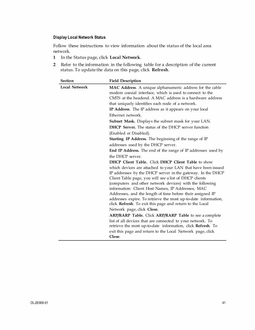
OL-26909-01 41
Display Local Network Status
Follow these instructions to view information about the status of the local area
network.
1 In the Status page, click Local Network.
2 Refer to the information in the following table for a description of the current status. To update the data on this page, click Refresh.
Section Field Description
Local Network MAC Address. A unique alphanumeric address for the cable
modem coaxial interface, which is used to connect to the
CMTS at the headend. A MAC address is a hardware address
that uniquely identifies each node of a network.
IP Address. The IP address as it appears on your local
Ethernet network.
Subnet Mask. Displays the subnet mask for your LAN.
DHCP Server. The status of the DHCP server function
(Enabled or Disabled).
Starting IP Address. The beginning of the range of IP
addresses used by the DHCP server.
End IP Address. The end of the range of IP addresses used by
the DHCP server.
DHCP Client Table. Click DHCP Client Table to show
which devices are attached to your LAN that have been issued
IP addresses by the DHCP server in the gateway. In the DHCP
Client Table page, you will see a list of DHCP clients
(computers and other network devices) with the following
information: Client Host Names, IP Addresses, MAC
Addresses, and the length of time before their assigned IP
addresses expire. To retrieve the most up-to-date information, click Refresh. To exit this page and return to the Local
Network page, click Close.
ARP/RARP Table. Click ARP/RARP Table to see a complete
list of all devices that are connected to your network. To retrieve the most up-to-date information, click Refresh. To
exit this page and return to the Local Network page, click
Close.

42 OL-26909-01
Display Wireless Network Status
Follow these instructions to view information about the status of the wireless
network.
1 In the Status page, click Wireless Network.
2 Refer to the information in the following table for a description of the settings. To update the data on this page, click Refresh.
Section Field Description
Wi-Fi Radio 1 Network Current. Displays one of the following radio band
frequencies currently in operation:
2.4 GHz
5 GHz
2.4 and 5 GHz
Note: Not all products support the 5 GHz radio band.
Network Name (SSID). The name or Service Set Identifier
(SSID) of your wireless access point.
Radio MAC Address. The MAC address of your gateway's
local wireless access point.
Network Mode. The wireless standard used by the wireless
access point.
Channel Width. The Channel Width setting as shown in the
Wireless Radio Settings page for the Wi-Fi Radio 1 Network.
Channel. The Channel setting as shown in the Wireless
Radio Settings page for the Wi-Fi Radio 1 Network.
Extended Channel. The Extended Channel setting as shown
on the Wireless Radio Settings page for the Wi-Fi Radio 1
Network.
Security. The security method used by your wireless
network.
SSID Broadcast. The status of the Wireless Residential
Gateway software's SSID Broadcast feature.

OL-26909-01 43
Section Field Description
Wi-Fi Radio 2 Network Current. Displays one of the following radio band
frequencies currently in operation:
2.4 GHz
5 GHz
2.4 and 5 GHz
Note: Not all products support the 5 GHz radio band.
Network Name (SSID). The name or Service Set Identifier
(SSID) of your wireless access point.
Radio MAC Address. The MAC address of your gateway's
local wireless access point.
Network Mode. The wireless standard used by the wireless
access point.
Channel Width. The Channel Width setting as shown in the
Wireless Radio Settings page for the Wi-Fi Radio 2 Network.
Channel. The Channel setting as shown in the Wireless
Radio Settings page for the Wi-Fi Radio 2 Network.
Extended Channel. The Extended Channel setting as shown
on the Wireless Radio Settings page for the Wi-Fi Radio 2
Network.
Security. The security method used by your wireless
network.
SSID Broadcast. The status of the Wireless Residential
Gateway software's SSID Broadcast feature.

44 OL-26909-01
Display Voice Status
Follow these instructions to view information about the status of the wireless
network.
1 In the Status page, click Voice.
2 Refer to the information in the following table for a description of the settings. To update the data in this page, click Refresh.
Section Field Description
Voice State Telephony-DHCP. DHCP status for the Voice component
of the gateway. Once the voice component has received an
IP address, this state will be Completed.
Telephony-Security. Status of voice security with
Kerberos. Disabled shows that the gateway is not
provisioned to use full Kerberos security.
Telephony-TFTP. TFTP status for the voice component of
the gateway. After the voice configuration file has been
downloaded successfully, this state will show Completed.
Telephony-Reg with Call Server. Registration status for
Line 1 of the voice gateway. Status can be connected
(registered successfully) or disconnected (not registered). A
connected status is required for voice service to be
operational.
Telephony-Reg with Call Server. Registration status for
Line 2 of the voice gateway. The status can be connected
(registered successfully) or disconnected (not registered).
The connected status is required for voice service to be
operational.
Telephony-Reg Complete. Displays status of the overall
voice component registration for the gateway. Pass is the
required status for voice service.
Voice Line State Line. Voice line number (1 or 2)
Hook Status. Status of the onhook state of each line. This
can be onhook (phone is on its hook and not active) or
offhook (phone has been picked up with dialtone).
Endpoint State. Voice status with the Service Provider
network. The status can be Disconnected (not operational)
or Connected (operational with dial tone).

OL-26909-01 45
Display DOCSIS WAN Status
Follow these instructions to view information about the status of the DOCSIS WAN.
1 In the Status page, click DOCSIS WAN.
2 Refer to the information in the following table for a description of the settings. To
update the data in this page, click Refresh.
Section Field Description
About Model. The name of the Wireless Residential
Gateway software.
Vendor. The manufacturer of the Wireless
Residential Gateway software.
Hardware Revision. The revision of the circuit board
design.
Serial Number. The unique serial of the Wireless
Residential Gateway software.
MAC Address. A unique alphanumeric address for
the cable modem coaxial interface, which is used to
connect to the CMTS at the headend. A MAC address
is a hardware address that uniquely identifies each
node of a network.
Bootloader Revision. The boot revision code version.
Current Software Revision. The revision version of
the firmware.
Firmware Name. The name of the firmware.
Firmware Build Time. The date and time that the
firmware was built.
Cable Modem Status. Displays one of the possible
current states of the Wireless Residential Gateway
software.
Wireless Network:
Wireless Network 1: The status (enable or disable)
for this wireless network.
Wireless Network 2: The status (enable or disable)
for this wireless network.

46 OL-26909-01
Section Field Description
Cable Modem State DOCSIS Downstream Scanning. The status of
DOCSIS downstream scanning on the gateway. The
status should show Completed when locked on a
downstream frequency (online and operational).
DOCSIS Ranging. The status of DOCSIS upstream
ranging on the gateway. The status should show
Completed when locked on a downstream frequency
(online and operational).
DOCSIS DHCP. The status of CM DHCP on the
gateway. The status should show Completed when
the gateway has successfully received a DHCP IP
address (online and operational).
DOCSIS TFTP. The status of DOCSIS TFTP of the
CM configuration file on the gateway. The status
should show Completed when the gateway has successfully received its configuration file (online
and operational).
DOCSIS Data Reg Complete. The status of DOCSIS
registration on the gateway with the Service Provider
headend. The status should show Completed when
the gateway has successfully come online and is
operation with the Service Provider headend.
DOCSIS Privacy. The status of DOCSIS privacy on
the gateway. The status will show Enabled or
Disabled depending on how the Service Provider has
configured the headend network.
Downstream Channels Channels 1-8. Displays the power level and the
signal to noise ratio of the active downstream
channels.
Upstream Channels Channels 1-4. Displays the power level of the active
upstream channels.

OL-26909-01 47
Display DOCSIS Log Status
Follow these instructions to view the DOCSIS Log status.
1 In the Status page, click DOCSIS Log.
2 Refer to the information in the following table for a description of the settings. To
update the data in this page, click Refresh.
Section Field Description
DOCSIS Log Lists the following data for each event that the
gateway has logged:
Count. The number of occurrences of a specific
DOCSIS Event ID.
Time. The date and time that the event was logged.
ID. A unique ID assigned to each event logged
Level. The level of event severity.
Description. A description of the event.
Complete a Speed Test
Follow these instructions to complete a speed test.
1 In the Status page, click SpeedTest.
2 To test the download and upload speed, click Start. The upload and download
speed is displayed in the Download speed and Upload speed fields.
Note: To cancel the test click Cancel. To update the data in this page, click
Refresh.

48 OL-26909-01
Configure Storage and Sharing
This section provides procedures for configuring the options available in the Storage
& Sharing page.
Display USB Settings
Follow these instructions to configure USB settings.
1 In the Storage & Sharing page, click USB Settings.
2 Use the information in the following table to change the settings.
Section Field Description
Basic Settings Enable USB Devices connected to the USB port. Select one of
the following options:
All. Select to allow all USB devices connected to the USB
port. (This is the default setting.)
Approved. Select to allow only approved USB devices to
connect to the USB port.
None. Select to prevent any USB devices from connecting
to the USB port.
Enable USB Devices to be Shared Storage. Select Yes to allow
USB devices to be shared storage, or select No if you do not
want USB devices to be shared storage.
Enable the Media Server (DLNA). Select Yes to enable the
Media server, or select No to disable the Media server.
Apply. Click to apply the changes that you have made to USB
settings.

OL-26909-01 49
Section Field Description
Approved Devices Available USB Devices. Displays the USB devices that
the residential gateway supports. The following data is
shown for each USB device listed in the table:
Volume Name. Name of the device.
Manufacturer. Manufacturer of the USB device.
Free Space. Free space remaining on the USB device.
Used Space. Used space on the USB device.
Total Space. Total space on the USB device.
SMART Status. Self-Monitoring, Analysis and Reporting
Technology (SMART) status if the USB device supports
this technology.
Approved Device. Indicates whether the USB device has
been approved for use on the gateway.
Add to Approved Devices. Adds any selected USB
devices as an approved device for the gateway. Until a
device is approved, it will not be usable by any of the
Gateway NAS/Media Server features
Remove from Approved Devices. Removes any selected
USB devices as an approved device for the gateway.
Unapproved devices cannot be used by other Gateway
services.
Safely Remove Device. Safely unmounts any selected
USB device. This is recommended before unplugging the
USB device from the gateway.
Refresh List. Updates data in the Approved Devices list
to display any changes in status or USB devices.

50 OL-26909-01
Display NAS Settings
Follow these instructions to configure Network-Attached Storage (NAS) settings.
1 In the Storage & Sharing page, click NAS.
2 Use the information in the following table to change the settings. When you have
finished changing these settings, click Save Settings to apply your changes or
click Cancel Changes to prevent the changes from being saved.
Section Field Description
Basic NAS Settings Network/Device Name. The name of the network to which
the gateway belongs.
Workgroup Name. The name of the workgroup to which
the gateway belongs.
Advanced NAS Settings The Protocols table provides the following information:
Enable. Select to enable this access method, or clear to disable this access method. Make sure to click Save
Settings after modifying this setting.
Access Method. Windows Network Connection
(SAMBA) or FTP is the available choices for access into
the attached NAS (USB) devices.
Link. File link to the associated access method service
to any attached USB devices.
Port. Port associated with the NAS service.
Display Media Server Settings
Follow these instructions to configure Media Server settings.
1 In the Storage & Sharing page, click Media Server .
2 Use the information in the following table to change the settings. When you have
finished changing these settings, click Save Settings to apply your changes or
click Cancel Changes to prevent the changes from being saved.
Section Field Description
Media Server Basic
Settings Media Server. Select to enable or disable the media server.
Media Server Name. Lists the name of the media server. To
change the media server name, enter the desired name in the
Media Server Name field and click Apply Basic Settings.
Apply Basic Settings. Click to apply changes that you have
made to basic settings fields.
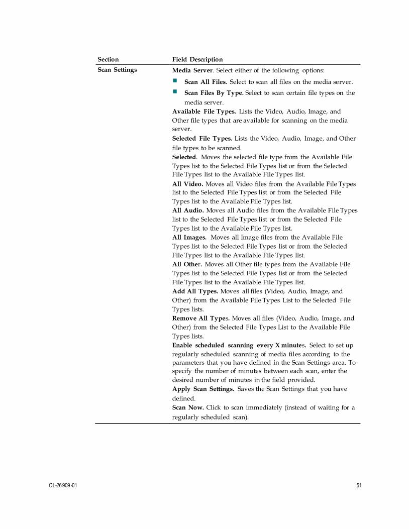
OL-26909-01 51
Section Field Description
Scan Settings Media Server. Select either of the following options:
Scan All Files. Select to scan all files on the media server.
Scan Files By Type. Select to scan certain file types on the
media server.
Available File Types. Lists the Video, Audio, Image, and
Other file types that are available for scanning on the media
server.
Selected File Types. Lists the Video, Audio, Image, and Other
file types to be scanned.
Selected. Moves the selected file type from the Available File
Types list to the Selected File Types list or from the Selected
File Types list to the Available File Types list.
All Video. Moves all Video files from the Available File Types
list to the Selected File Types list or from the Selected File
Types list to the Available File Types list.
All Audio. Moves all Audio files from the Available File Types
list to the Selected File Types list or from the Selected F ile
Types list to the Available File Types list.
All Images. Moves all Image files from the Available File
Types list to the Selected File Types list or from the Selected
File Types list to the Available File Types list.
All Other. Moves all Other file types from the Available File
Types list to the Selected File Types list or from the Selected
File Types list to the Available File Types list.
Add All Types. Moves all files (Video, Audio, Image, and
Other) from the Available File Types List to the Selected File
Types lists.
Remove All Types. Moves all files (Video, Audio, Image, and
Other) from the Selected File Types List to the Available File
Types lists.
Enable scheduled scanning every X minutes. Select to set up
regularly scheduled scanning of media files according to the
parameters that you have defined in the Scan Settings area. To
specify the number of minutes between each scan, enter the
desired number of minutes in the field provided.
Apply Scan Settings. Saves the Scan Settings that you have
defined.
Scan Now. Click to scan immediately (instead of waiting for a
regularly scheduled scan).

52 OL-26909-01
For Information
Log Off and Log In to the Residential Gateway
Follow these instructions to log off the residential gateway.
1 Click Log Off. The Status DOCSIS WAN page appears.
2 To log back on to the gateway, enter your user name and password in the fields provided, and click Log In.

OL-26909-01 53
For Information
Troubleshooting
This section describes the most common issues that may occur after the Wireless
Residential Gateway software is installed and provides possible solutions and tips
for improved performance of the Wireless Residential Gateway software.
Frequently Asked Questions
This section provides answers to common questions about the Wireless Residential
Gateway software.
How Do I Configure TCP/IP Protocol?
To configure TCP/IP protocol, you need to have an Ethernet Network Interface Card
(NIC) with TCP/IP communications protocol installed on your system. TCP/IP is a
communications protocol used to access the Internet. This section contains
instructions for configuring TCP/IP on your Internet devices to operate with the
Wireless Residential Gateway software in Microsoft Windows or Macintosh
environments.
TCP/IP protocol in a Microsoft Windows environment is different for each
operating system. Follow the appropriate instructions in this section for your
operating system.
Configuring TCP/IP on Window s 7 Sy stems
1 Open Network Connections by clicking the Start button, and then clicking
Control Panel.
2 In the Search field, type adapter , and then, under Network and Sharing Center ,
click View network connections.
3 Right-click the connection that you want to change, and then click Properties. If
you are prompted for an administrator password or confirmation, type the
password or provide confirmation. The Local Area Connection Properties
window appears.
4 Click the Networking tab.
5 Under This connection uses the following items, click either Internet Protocol
Version 4 (TCP/IPv4) or Internet Protocol Version 6 (TCP/IPv6) , and then click
Properties.
6 To specify IPv4 IP address settings, do one of the following:
To get IP settings automatically using DHCP, click Obtain an IP address
automatically, and then click OK.
To specify an IP address, click Use the following IP address, and then, in the
IP address, Subnet mask, and Default gateway fields, type the IP address
settings.

54 4009700 Rev A
7 To specify IPv6 IP address settings, do one of the following:
To get IP settings automatically using DHCP, click Obtain an IPv6 address
automatically, and then click OK.
To specify an IP address, click Use the following IPv6 address, and then, in
the IPv6 address, Subnet prefix length, and the Default gateway fields, type
the IP address settings.
8 To specify DNS server address settings, do one of the following:
To get a DNS server address automatically using DHCP, click Obtain DNS
server address automatically, and then click OK.
To specify a DNS server address, click Use the following DNS server
addresses, and then, in the Preferred DNS server and Alternate DNS server
fields, type the addresses of the primary and secondary DNS servers.
9 To change advanced DNS, WINS, and IP settings, click Advanced.
10 When you are finished, click OK.
11 Try to access the Internet. If you cannot access the Internet, contact your service
provider for further assistance.
Configuring TCP/IP on Window s XP Sy stems
1 Click Start, and depending on your Start menu setup, choose one of the
following options:
If you are using the Windows XP Default Start menu, select Connect to,
choose Show all connections, and then go to Step 2.
If you are using the Windows XP Classic Start menu, select Settings, choose
Network Connections, click Local Area Connection, and then go to Step 3.
2 Double-click the Local Area Connection icon in the LAN or High-Speed Internet
section of the Network Connections window.
3 Click Properties in the Local Area Connection Status window.
4 Click Internet Protocol (TCP/IP), and then click Properties in the Local Area
Connection Properties window.
5 Select both Obtain an IP address automatically and Obtain DNS server address
automatically in the Internet Protocol (TCP/IP) Properties window, and then
click OK.
6 Click Yes to restart your computer when the Local Network window appears.
The computer restarts. The TCP/IP protocol is now configured on your PC, and
your Ethernet devices are ready for use.
7 Try to access the Internet. If you cannot access the Internet, contact your service
provider for further assistance.
Configuring TCP/IP on Macintosh Sy stems
1 Click the Apple icon in the upper-left corner of the Finder. Scroll down to
Control Panels, and then click TCP/IP.
2 Click Edit on the Finder at the top of the screen. Scroll down to the bottom of the
menu, and then click User Mode.
3 Click Advanced in the User Mode window, and then click OK.
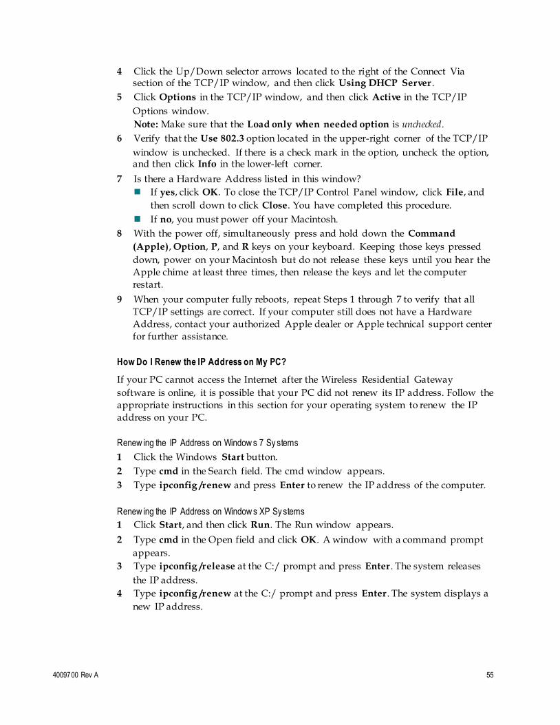
4009700 Rev A 55
4 Click the Up/Down selector arrows located to the right of the Connect Via section of the TCP/IP window, and then click Using DHCP Server .
5 Click Options in the TCP/IP window, and then click Active in the TCP/IP
Options window.
Note: Make sure that the Load only when needed option is unchecked.
6 Verify that the Use 802.3 option located in the upper-right corner of the TCP/IP
window is unchecked. If there is a check mark in the option, uncheck the option, and then click Info in the lower-left corner.
7 Is there a Hardware Address listed in this window?
If yes, click OK. To close the TCP/IP Control Panel window, click File, and
then scroll down to click Close. You have completed this procedure.
If no, you must power off your Macintosh.
8 With the power off, simultaneously press and hold down the Command
(Apple), Option, P, and R keys on your keyboard. Keeping those keys pressed
down, power on your Macintosh but do not release these keys until you hear the
Apple chime at least three times, then release the keys and let the computer
restart.
9 When your computer fully reboots, repeat Steps 1 through 7 to verify that all
TCP/IP settings are correct. If your computer still does not have a Hardware
Address, contact your authorized Apple dealer or Apple technical support center
for further assistance.
How Do I Renew the IP Address on My PC?
If your PC cannot access the Internet after the Wireless Residential Gateway
software is online, it is possible that your PC did not renew its IP address. Follow the
appropriate instructions in this section for your operating system to renew the IP
address on your PC.
Renew ing the IP Address on Window s 7 Sy stems
1 Click the Windows Start button.
2 Type cmd in the Search field. The cmd window appears.
3 Type ipconfig /renew and press Enter to renew the IP address of the computer.
Renew ing the IP Address on Window s XP Sy stems
1 Click Start, and then click Run. The Run window appears.
2 Type cmd in the Open field and click OK. A window with a command prompt
appears.
3 Type ipconfig /release at the C:/ prompt and press Enter. The system releases
the IP address.
4 Type ipconfig /renew at the C:/ prompt and press Enter. The system displays a
new IP address.

56 4009700 Rev A
5 Click the X in the upper-right corner of the window to close the Command
Prompt window. You have completed this procedure.
Note: If you cannot access the Internet, contact your service provider for further
assistance.
Renew ing the IP Address on Macintosh Sy stems
1 Close all open programs.
2 Open your Preferences folder.
3 Drag the tcp/ip preferences file to the Trash.
4 Close all open windows and empty the Trash.
5 Restart your computer.
6 As your computer starts, simultaneously press and hold down the Command
(Apple), Option, P, and R keys on your keyboard. Keeping those keys pressed
down, power on your Macintosh but do not release these keys until you hear the
Apple chime at least three times, release the keys and let the computer restart.
7 When your computer fully reboots, click the Apple icon in the upper-left corner
of the Finder. Scroll down to Control Panels, and then click TCP/IP.
8 Click Edit on the Finder at the top of the screen. Scroll down to the bottom of the
menu, and then click User Mode.
9 Click Advanced in the User Mode window, and then click OK.
10 Click the Up/Down selector arrows located to the right of the Connect Via section of the TCP/IP window, and then click Using DHCP Server .
11 Click Options in the TCP/IP window, and then click Active in the TCP/IP
Options window.
Note: In some cases, the Load only when needed option does not appear. If it
appears, select the option. A check mark appears in the option.
12 Verify that the Use 802.3 option located in the upper-right corner of the TCP/IP
window is not selected. If there is a check mark in the option, select the option to clear the check mark, and then click Info in the lower-left corner.
13 Is there a Hardware Address listed in this window?
If yes, click OK. To close the TCP/IP Control Panel window, click File, and
then scroll down to click Close.
If no, repeat these instructions from Step 6.
14 Reboot your computer.

4009700 Rev A 57
What if I Don NotSubscribe to Cable TV?
If cable TV is available in your area, data service may be made available with or
without subscribing to cable TV service. Contact your local service provider for
complete information on cable services, including high-speed Internet access.
How Do I Arrange for Installation?
Call your service provider to inquire about professional installation. A professional
installation ensures proper cable connection to the Wireless Residential Gateway
software and to your PC, and it ensures the proper configuration of all hardware
and software settings. Contact your service provider for more information about
installation.
How Does the Wireless Residential Gateway Connect to My Computer?
The Wireless Residential Gateway software connects to the 10/100/1000BASE-T
Ethernet port on your PC. To use the Ethernet interface, your PC needs Ethernet
cards. These cards are available from your local PC or office supply retailer, or from
your service provider. For best performance over an Ethernet connection, your PC
should be equipped with a Gigabit Ethernet card.
After My Wireless Residential Gateway Is Connected, How Do I Access the Internet?
Your local service provider becomes your Internet service provider (ISP). They offer
a wide range of services including email, chat, news, and information services. Your
service provider will provide the software that you will need.
Can I Watch TV and Surf the Internet at the Same Time?
Absolutely! If you subscribe to cable television service, you can watch TV and use
your Wireless Residential Gateway software at the same time by connecting your TV
and your Wireless Residential Gateway software to the cable network using an
optional cable signal splitter.
Can I Use my Existing Phone Number with the Wireless Residential Gateway?
Telephone numbers are portable in some areas. Contact your telephone service
provider for more information about using an existing telephone number.
How Many Telephones Can I Connect?
The RJ-11 telephone-style connectors on the Wireless Residential Gateway software
can each provide telephone service to multiple telephones, fax machines, and analog
modems. The maximum number of telephone devices connected to each RJ -11 port
is limited by the total Ringing Load of the telephone devices that are connected.
Many telephone devices are marked with a Ringer Equivalent Number (REN). Each
telephone port on the Wireless Residential Gateway software can support up to a 5
REN load. The sum of the REN load on all of the telephone devices attached to each
port must not exceed 5 REN.

58 4009700 Rev A
Common Troubleshooting Issues
This section describes common problems and offers solutions.
I don't understand the front panel status indicators
See Operation of Front Panel Indicators, for more detailed information on front
panel LED status indicator operation and function.
The Wireless Residential Gatew ay does not register an Ethernet connection
Try one of the following solutions:
Verify that your computer has an Ethernet card and that the Ethernet driver
software is properly installed. If you purchase and install an Ethernet card,
follow the installation instructions very carefully.
Verify the status of the front panel status indicator lights.
The Wireless Residential Gatew ay does not register an Ethernet connection after connecting to a hub
If you are connecting multiple PCs to the Wireless Residential Gateway software,
you should first connect the Wireless Residential Gateway software to the uplink
port of the hub using the correct crossover cable. The LINK LED of the hub will
illuminate continuously.
The Wireless Residential Gatew ay does not register a cable connection
The Wireless Residential Gateway software works with a standard, 75 -ohm, RF
coaxial cable. If you are using a different cable, your Wireless Residential Gateway
software will not function properly. Contact your service provider to determine
whether you are using the correct cable.
There is no dial tone w hen I lift the handset
Try the following solutions if you cannot hear a dial tone:
Your telephone wiring may be connected to the wrong RJ-11 port on the Wireless
Residential Gateway software. The Wireless Residential Gateway software has
two telephone ports. Verify that you are connected to the correct telephone port.
There may be a problem with your telephone set. Use a different telephone set
and listen to hear dial tone.
There may be a problem with your home telephone wiring. Use a telephone and
connect directly to the same RJ-11 port on the back of the unit. If the dial tone is
working here but does not work at other locations in the home, a professional
may need to diagnose and repair a problem with your telephone wiring.
Verify that the telephone company has removed the previous telephone service
from your home telephone wiring.

4009700 Rev A 59
Your telephone service may not be enabled from your cable telephony service
provider. Contact your cable telephony service provider for more information.
Tips for Improved Performance
If your Wireless Residential Gateway software does not perform as expected, the
following tips may help. If you need further assistance, contact your service
provider.
Verify that the plug to your Wireless Residential Gateway software AC power is
properly inserted into an electrical outlet.
Verify that your Wireless Residential Gateway software AC power cord is not
plugged into an electrical outlet that is controlled by a wall switch. If a wall switch controls the electrical outlet, make sure the switch is in the ON position.
Verify that the ONLINE LED status indicator on the front panel of your Wireless
Residential Gateway software is illuminated.
Verify that your cable service is active and that it supports two-way service.
Verify that all cables are properly connected, and that you are using the correct
cables.
If you are using the Ethernet connection, verify that your TCP/IP is properly
installed and configured.
Verify that you have called your service provider and given them the serial
number and MAC address of your Wireless Residential Gateway software.
If you are using a cable signal splitter so that you can connect the Wireless
Residential Gateway software to other devices, remove the splitter and reconnect
the cables so that the Wireless Residential Gateway software is connected
directly to the cable input. If the Wireless Residential Gateway software now
functions properly, the cable signal splitter may be defective and may need to be
replaced.
If you are connected to your PC with an Ethernet connection, your PC should be
equipped with a Gigabit Ethernet card for best performance.
If your Wireless Residential Gateway software has a USB port and you are
connected to that port, verify that you have followed the procedures in Install
USB Drivers on Your PC (Optional).
For Information
If You Have Questions
If you have technical questions, contact Cisco Services for assistance. Follow the
menu options to speak with a service engineer.
Americas Headquarters
Cisco Systems, Inc.
170 West Tasman Drive
San Jose, CA 95134-1706
USA
http://www.cisco.com
Tel: +1-408 526-4000
+1-800 553-6387
Fax: +1-408 527-0883
Cisco and the Cisco logo are trademarks or registered trademarks of Cisco and/or its affiliates
in the U.S. and other countries. To view a list of Cisco trademarks, go to this URL: www.cisco.com/go/trademarks .
Third party trademarks mentioned are the property of their respective owners.
The use of the word partner does not imply a partnership relationship between Cisco and any
other company. (1110R)
Product and service availability are subject to change without notice.
© 2014 Cisco and/or its affiliates. All rights reserved.
June 2014 Part Number OL-26909-01