wireless speed and direction control of dc motor using rf technology
DESCRIPTION
Using relay circuits, microcontrollers.TRANSCRIPT

1
CHAPTER 1
INTRODUCTION

2
INTRODUCTION
The speed and direction control of DC motor is very important for various kind of uses.
Through all these years, there have been various attempts in finding different efficient solutions
for the speed and direction control of the DC motor.
History will recognize the vital role played by DC motors in the development of
industrial power transmission systems. The DC machine was the first practical device to convert
electrical power into mechanical power, and vice-versa in its generator form. Inherently
straightforward operating characteristics, flexible performance and high efficiency encouraged
the widespread use of DC motors in many types of industrial drive applications.
DC motors have been long been the primary means of Electrical traction. DC motor is
considered as a SISO system having torque/speed characteristics compatible with most
mechanical loads. Hence, DC motors are always a good ground for advanced theories because
the theory is extendable to other types of motors.
Wireless communication is the transfer of information between two or more points that
are not physically connected. Distances can be short, such as a few meters for television remote
control, or as far as thousands or even millions of kilometers. Among the various wireless
technologies like IR (Infra Red), Bluetooth and WLAN, we have chosen RF technology, the
main reason being it has a very long range of 3 KHz-300GHZ. It is also not affected by any
obstructions. Commercial applications for wireless are door announcers, security and access
systems, gate control, remote activation, score board and paging systems.
In this project we try to provide a similar approach by introducing the concept of radio
frequency technology.

3
CHAPTER 2
WIRELESS COMMUNICATIONS
4
WIRELESS COMMUNICATIONS
Wireless communication is the transfer of information over a distance without the use of
electrical conductors or "wires". The distances involved may be short (a few meters as in
television remote control) or long (thousands or millions of kilometers for radio
communications). Wireless communication is generally considered to be a branch of
telecommunications. It encompasses various types of fixed, mobile, and portable two-way
radios, cellular telephones, personal digital assistants (PDAs), and wireless networking. Other
examples of wireless technology include GPS units, garage door openers and or garage doors,
wireless computer mice, keyboards and headsets, satellite television and cordless telephones.
Wireless operations permits services, such as long-range communications, that are
impossible or impractical to implement with the use of wires. The term is commonly used in the
telecommunications industry to refer to telecommunications systems (e.g. radio transmitters and
receivers, remote controls, computer networks, network terminals, etc.) which use some form of
energy (e.g. radio frequency (RF), infrared light, laser light, visible light, acoustic energy, etc.) to
transfer information without the use of wires. Information is transferred in this manner over both
short and long distances. In 1895, Guglielmo Marconi opened the way for modern wireless
communications by transmitting the three-dot Morse code for the letter ‘S’ over a distance of
three kilometers using electromagnetic waves. From this beginning, wireless communications
has developed into a key element of modern society. From satellite transmission, radio and
television broadcasting to the now ubiquitous mobile telephone, wireless communications has
revolutionized the way societies function.
Wireless communications and the economic goods and services that utilize it have some
special characteristics that have motivated specialized studies. First, wireless communications
relies on a scarce resource – namely, radio spectrum. Second, use of spectrum for wireless
communications required the development of key complementary technologies; especially those
that allowed higher frequencies to be utilized more efficiently. Finally, because of its special
nature, the efficient use of spectrum required the coordinated development of standards. Those
standards in turn played a critical role in the diffusion of technologies that relied on spectrum
use. Wireless operations permits services, such as long range communications, that are

5
impossible or impractical to implement with the use of wires. The term is commonly used in the
telecommunications industry to refer to telecommunications systems (e.g. radio transmitters and
receivers, remote controls, computer networks, network terminals, etc.) which use some form of
energy (e.g. radio frequency (RF),acoustic energy, etc.) to transfer information without the use of
wires. Information is transferred in this manner over both short and long distances.
Wireless networking (i.e. the various types of unlicensed 2.4 GHz Wi-Fi devices) is used
to meet many needs. Perhaps the most common use is to connect laptop users who travel from
location to location. Another common use is for mobile networks that connect via satellite. A
wireless transmission method is a logical choice to network a LAN segment that must frequently
change locations. The following situations justify the use of wireless technology:
To span a distance beyond the capabilities of typical cabling,
To provide a backup communications link in case of normal network failure,
To link portable or temporary workstations,
To overcome situations where normal cabling is difficult or financially impractical, or
To remotely connect mobile users or networks.
The term "wireless" came into public use to refer to a radio receiver or transceiver (a dual
purpose receiver and transmitter device), establishing its usage in the field of wireless telegraphy
early on; now the term is used to describe modern wireless connections such as in cellular
networks and wireless broadband Internet. It is also used in a general sense to refer to any type of
operation that is implemented without the use of wires, such as "wireless remote control" or
"wireless energy transfer", regardless of the specific technology (e.g. radio, infrared, ultrasonic)
used.
2.1. PRINCIPLES OF WIRELESS COMMUNICATIONS:
Wireless communications begin with a message that is converted into an electronic signal
by a device called a transmitter. There are two types of transmitters: analog and digital. An
analog transmitter sends electronic signals as modulated radio waves. The analog transmitter
modulates the radio wave to carry the electronic signal and then sends the modified radio signal
6
through space. A digital transmitter encodes electronic signals by converting messages into a
binary code, the series of zeros and ones that are the basis of all computer programming. The
encoded electronic signal is then sent as a radio wave. Devices known as receivers decode or
demodulate the radio waves and reproduce the original message over a speaker.
Wireless communications systems involve either one-way transmissions, in which a
person merely receives notice of a message, or two-way transmissions, such as a telephone
conversation between two people. An example of a device that only receives one-way
transmission is a pager, which is a high-frequency radio receiver. When a person dials a pager
number, the pager company sends a radio signal to the desired pager. The encoded signal triggers
the pager’s circuitry and notifies the customer carrying the pager of the incoming call with a tone
or a vibration, and often the telephone number of the caller. Advanced pagers can display short
messages from the caller, or provide news updates or sports scores.
Two-way transmissions require both a transmitter and a receiver for sending and
receiving signals. A device that functions as both a transmitter and a receiver is called a
transceiver. Cellular radio telephones and two-way radios use transceivers, so that back-and-
forth communication between two people can be maintained. Early transceivers were very large,
but they have decreased in size due to advances in technology. Fixed-base transceivers, such as
those used at police stations, can fit on a desktop, and hand-held transceivers have shrunk in size
as well. Several current models of handheld transceivers weigh less than 0.2 kg (0.5 lb). Some
pagers also use transceivers to provide limited response options. These brief return-
communication opportunities allow paging users to acknowledge reception of a page and to
respond using a limited menu of options.

7
Fig2.1: Principle of wireless communications
2.2. TYPES OF WIRELESS COMMUNICATION:
1. Infrared Wireless Transmission- "Transmission of data signals using infrared-light
waves". These infrared-light waves are at a frequency too low for human eyes to receive
and interpret. Infrared ports can be found in digital cameras, laptops, and printers as well
as wireless mice.
2. Broadcast Radio- a wireless transmission medium that sends data over long distances
(regions, states, countries) at up to 2 megabits per second (AM/FM Radio).
3. Microwave Radio- Transmission of voice and data through the atmosphere as super high-
frequency radio waves called microwaves. These frequencies are used to transmit
messages between ground-based stations and satellite communications systems.
4. Communications Satellites- are microwave relay stations in orbit around the earth.
2.3. APPLICATIONS:
1. Broadcasting services: including short wave AM and FM radio as well as terrestrial
television.
2. Mobile communications of voice and data: including maritime and aeronautical mobile
for communications between ships, airplanes and land; land mobile for communications
between a fixed base station and moving sites such as a taxi fleet and paging services,
and mobile communications either between mobile users and a fixed network or between
mobile users, such as mobile telephone services
8
3. Fixed Services: either point to point or point to multipoint services
4. Satellite: used for broadcasting, telecommunications and internet, particularly over long
distances.
5. Professional LMR (Land Mobile Radio) and SMR (Specialized Mobile Radio) typically
used by business, industrial and Public Safety entities
6. Consumer Two Way Radio including FRS (Family Radio Service), GMRS (General
Mobile Radio Service) and Citizens band ("CB") radios.
7. Consumer and professional Marine VHF radios.
8. Cellular telephones and pagers: provide connectivity for portable and mobile
applications, both personal and business.
9. Global Positioning System (GPS): allows drivers of cars and trucks, captains of boats and
ships, and pilots of aircraft to ascertain their location anywhere on earth.
10. Cordless computer peripherals: the cordless mouse is a common example; keyboards and
printers can also be linked to a computer via wireless.
11. Cordless telephone sets: these are limited-range devices, not to be confused with cell
phones.
12. Satellite television: allows viewers in almost any location to select from hundreds of
channels.
13. Wireless gaming: new gaming consoles allow players to interact and play in the same
game regardless of whether they are playing on different consoles. Players can chat, send
text messages as well as record sound and send it to their friends.
14. Security systems: Wireless technology may supplement or replace hard wired
implementations in security systems for homes or office buildings.
15. Television remote control: Modern televisions use wireless (generally infrared) remote
control units. Now radio waves are also used.
16. Cellular telephony (phones and modems): These instruments use radio waves to enable
the operator to make phone calls from many locations world-wide. They can be used
anywhere that there is a cellular telephone site to house the equipment that is required to
transmit and receive the signal that is used to transfer both voice and data to and from
these instruments.
9
17. Wi-Fi: Wi-Fi (for wireless fidelity) is a wireless LAN technology that enables laptop
PC’s, PDA’s, and other devices to connect easily to the internet. Technically known as
IEEE 802.11 a,b,g,n, Wi-Fi is less expensive and nearing the speeds of standard Ethernet
and other common wire-based LAN technologies
18. Wireless energy transfer: Wireless energy transfer is a process whereby electrical energy
is transmitted from a power source to an electrical load that does not have a built-in
power source, without the use of interconnecting wires.
2.4. ADVANTAGES AND DISADVANTAGES:
ADVANTAGES:
1. Anywhere, Anytime Work
2. Through wireless communication, working professionals and mobile workers can work
and access the Internet just about anywhere, anytime without the hassles of wires and
network cables.
3. Enhanced Productivity
4. Workers, students, professionals and others need not be constrained by wired Internet
connections or dial-up connectivity. Wireless Internet connectivity options ensures that
work and assignments can be completed anywhere and enhance overall productivity of all
concerned.
5. Remote Area Connectivity
6. Workers, doctors and other professionals working in remote-location hospitals and
medical centers can keep in touch with anyone through wireless communication. Non-
profit organization volunteers working in remote and underserved areas can stay
connected to the outside world with the help of wireless communication.
7. For those unable to keep away from their daily soap operas, reality-programs, online TV
shows and Internet surfing or download activities, wireless communication ensures an
entertainment bonanza on--demand and anytime.
8. Emergency Alerts
10
9. Through wireless communication, many emergency situations and crisis situations can be
addressed quickly. Help and other assistance can reach affected areas quickly through
early alerts and warnings provided with the help of wireless communication.
DISADVANTAGES:
1. Wireless communications are limited by the range of the transmitter.
2. Cost of wireless communication system and components are high.
3. When transmitting data, users must sometimes send smaller bits of data so the
information moves more quickly. The size of the device that's accessing the information
is also still an issue.
4. Many applications need to be reconfigured if they are going to be used through wireless
connections.
5. Most client/server applications rely on a persistent connection, which is not the case with
wireless.
6. Since radio waves travel through the atmosphere they can be disturbed by electrical
interferences (such as lightning) that cause static.
2.5. RADIO FREQUENCY TECHNOLOGY:
RF refers to radio frequency, the mode of communication for wireless technologies of all
kinds, including cordless phones, radar, ham radio, GPS, and radio and television broadcasts.
RF technology is so much a part of our lives we scarcely notice it for its ubiquity. From baby
monitors to cell phones, Bluetooth® to remote control toys, RF waves are all around us. RF
waves are electromagnetic waves which propagate at the speed of light, or 186,000 miles per
second (300,000 km/s). The frequencies of RF waves, however, are slower than those of visible
light, making RF waves invisible to the human eye. Radio frequency (RF) is a frequency or rate
of oscillation within the range of about 3 Hz to 300 GHz. This range corresponds to frequency of
alternating current electrical signals used to produce and detect radio waves. Since most of this
range is beyond the vibration rate that most mechanical systems can respond to, it usually refers
to oscillations in electrical circuits or electromagnetic radiation.

11
The frequency of a wave is determined by its oscillations or cycles per second. One cycle is one
hertz (Hz); 1,000 cycles is 1 kilohertz (KHz); 1 million cycles is 1 megahertz (MHz); and 1
billion cycles is 1 gigahertz (GHz).
2.5.1. BRIEF DESCRIPTION OF RF:
Radio frequency (abbreviated RF) is a term that refers to alternating current (AC) having
characteristics such that, if the current is input to an antenna, an electromagnetic (EM) field is
generated suitable for wireless broadcasting and/or communications. These frequencies cover a
significant portion of the electromagnetic radiation spectrum, extending from nine kilohertz (9
kHz),the lowest allocated wireless communications frequency (it's within the range of human
hearing), to thousands of gigahertz(GHz).When an RF current is supplied to an antenna, it gives
rise to an electromagnetic field that propagates through space. This field is sometimes called an
RF field, in less technical jargon it is a "radio wave." Any RF field has a wavelength that is
inversely proportional to the frequency. In the atmosphere or in outer space, if f is the frequency
in megahertz and s is the wavelength in meters, then s = 300/f.
The frequency of an RF signal is inversely proportional to the wavelength of the EM field
to which it corresponds. At 9 kHz, the free-space wavelength is approximately 33 kilometers
(km) or 21 miles (mi). At the highest radio frequencies, the EM wavelengths measure
approximately one millimeter (1 mm). As the frequency is increased beyond that of the RF
spectrum, EM energy takes the form of infrared (IR), visible, ultraviolet (UV), X rays, and
gamma rays.
Many types of wireless devices make use of RF fields. Cordless and cellular telephone,
radio and television broadcast stations, satellite communications systems, and two-way radio
services all operate in the RF spectrum. Some wireless devices operate at IR or visible-light
frequencies, whose electromagnetic wavelengths are shorter than those of RF fields. Examples
include most television-set remote-control boxes some cordless computer keyboards and mice,
and a few wireless hi-fi stereo headsets.

12
2.5.2. PROPERTIES OF RF:
Electrical currents that oscillate at RF have special properties not shared by direct current
signals. One such property is the ease with which it can ionize air to create a conductive path
through air. This property is exploited by 'high frequency' units used in electric arc welding.
Another special property is an electromagnetic force that drives the RF current to the surface of
conductors, known as the skin effect. Another property is the ability to appear to flow through
paths that contain insulating material, like the dielectric insulator of a capacitor. The degree of
effect of these properties depends on the frequency of the signals.
Electric currents that oscillate at radio frequencies have special properties not shared by
direct current or alternating current of lower frequencies.
The energy in an RF current can radiate off a conductor into space as electromagnetic
waves (radio waves); this is the basis of radio technology.
RF current does not penetrate deeply into electrical conductors but flows along their
surfaces; this is known as the skin effect. For this reason, when the human body comes in
contact with high power RF currents it can cause superficial but serious burns called RF
burns.
RF current can easily ionize air, creating a conductive path through it. This property is
exploited by "high frequency" units used in electric arc welding, which use currents at
higher frequencies than power distribution uses.
Another property is the ability to appear to flow through paths that contain insulating
material, like the dielectric insulator of a capacitor. When conducted by an ordinary
electric cable, RF current has a tendency to reflect from discontinuities in the cable such
as connectors and travel back down the cable toward the source, causing a condition
called standing waves, so RF current must be carried by specialized types of cable called
transmission line.
13
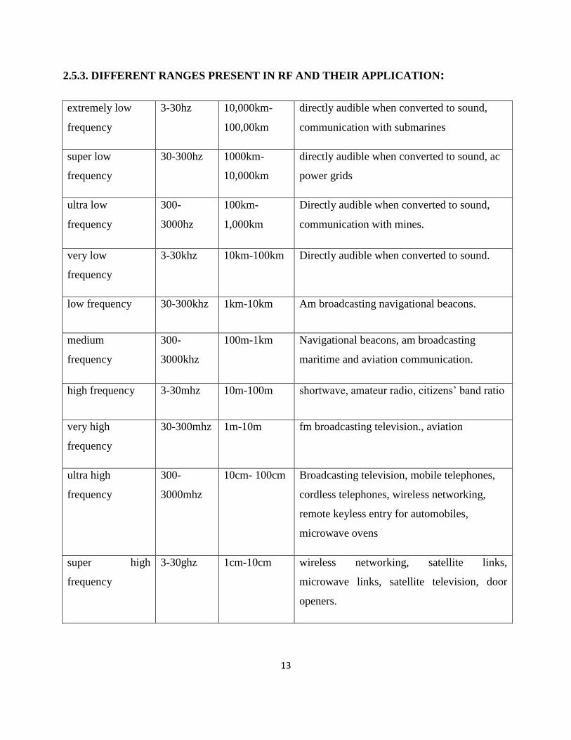
2.5.3. DIFFERENT RANGES PRESENT IN RF AND THEIR APPLICATION:
extremely low
frequency
3-30hz 10,000km-
100,00km
directly audible when converted to sound,
communication with submarines
super low
frequency
30-300hz 1000km-
10,000km
directly audible when converted to sound, ac
power grids
ultra low
frequency
300-
3000hz
100km-
1,000km
Directly audible when converted to sound,
communication with mines.
very low
frequency
3-30khz 10km-100km Directly audible when converted to sound.
low frequency 30-300khz 1km-10km Am broadcasting navigational beacons.
medium
frequency
300-
3000khz
100m-1km Navigational beacons, am broadcasting
maritime and aviation communication.
high frequency 3-30mhz 10m-100m shortwave, amateur radio, citizens’ band ratio
very high
frequency
30-300mhz 1m-10m fm broadcasting television., aviation
ultra high
frequency
300-
3000mhz
10cm- 100cm Broadcasting television, mobile telephones,
cordless telephones, wireless networking,
remote keyless entry for automobiles,
microwave ovens
super high
frequency
3-30ghz 1cm-10cm wireless networking, satellite links,
microwave links, satellite television, door
openers.

14
Table 2.1. Different ranges present in RF and their applications.
2.5.4. RF ADVANTAGES AND DISADVANTAGES:
ADVANTAGES:
1. No line of sight is needed.
2. Not blocked by common materials: It can penetrate most solids and pass through walls.
3. Longer range.
4. It is not sensitive to the light.
5. It is not much sensitive to the environmental changes and weather conditions.
DISADVANTAGES:
1. Interference: communication devices using similar frequencies - wireless phones, scanners,
wrist radios and personal locators can interfere with transmission.
2. Lack of security: easier to "eavesdrop" on transmissions since signals are spread out in
space rather than confined to a wire.
3. Higher cost than infrared.
4. Federal Communications Commission (FCC) licenses required for some products.
5. Lower speed: data rate transmission is lower than wired and infrared transmission.
extremely high
frequency
30-300ghz 1 mm-10mm microwave data links, radio astronomy,
remote sensing advanced weapons systems.
15
CHAPTER 3
DC MOTOR
16
DC MOTOR
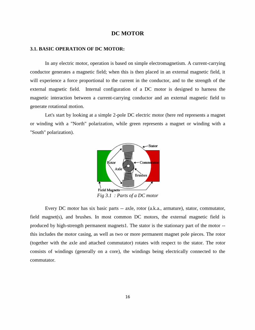
3.1. BASIC OPERATION OF DC MOTOR:
In any electric motor, operation is based on simple electromagnetism. A current-carrying
conductor generates a magnetic field; when this is then placed in an external magnetic field, it
will experience a force proportional to the current in the conductor, and to the strength of the
external magnetic field. Internal configuration of a DC motor is designed to harness the
magnetic interaction between a current-carrying conductor and an external magnetic field to
generate rotational motion.
Let's start by looking at a simple 2-pole DC electric motor (here red represents a magnet
or winding with a "North" polarization, while green represents a magnet or winding with a
"South" polarization).
Fig 3.1 : Parts of a DC motor
Every DC motor has six basic parts -- axle, rotor (a.k.a., armature), stator, commutator,
field magnet(s), and brushes. In most common DC motors, the external magnetic field is
produced by high-strength permanent magnets1. The stator is the stationary part of the motor --
this includes the motor casing, as well as two or more permanent magnet pole pieces. The rotor
(together with the axle and attached commutator) rotates with respect to the stator. The rotor
consists of windings (generally on a core), the windings being electrically connected to the
commutator.
17
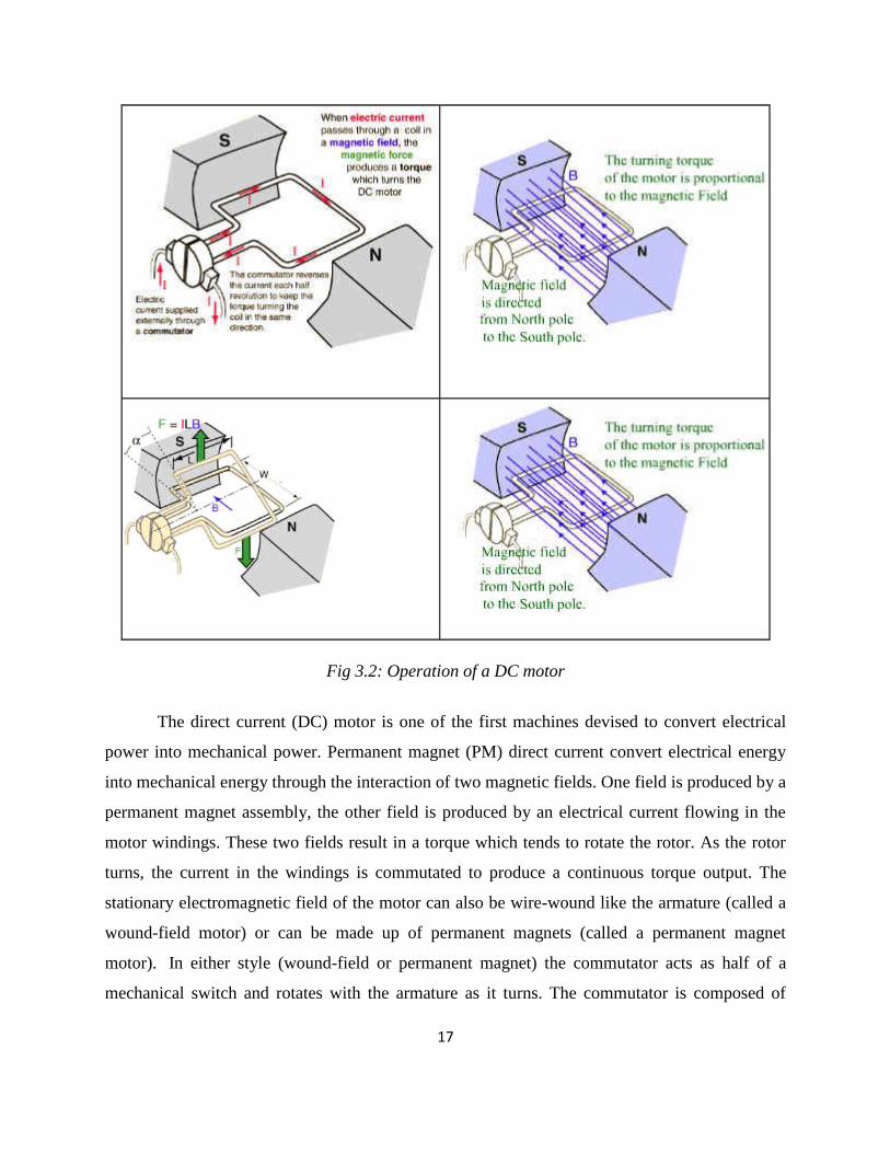
Fig 3.2: Operation of a DC motor
The direct current (DC) motor is one of the first machines devised to convert electrical
power into mechanical power. Permanent magnet (PM) direct current convert electrical energy
into mechanical energy through the interaction of two magnetic fields. One field is produced by a
permanent magnet assembly, the other field is produced by an electrical current flowing in the
motor windings. These two fields result in a torque which tends to rotate the rotor. As the rotor
turns, the current in the windings is commutated to produce a continuous torque output. The
stationary electromagnetic field of the motor can also be wire-wound like the armature (called a
wound-field motor) or can be made up of permanent magnets (called a permanent magnet
motor). In either style (wound-field or permanent magnet) the commutator acts as half of a
mechanical switch and rotates with the armature as it turns. The commutator is composed of
18
conductive segments (called bars), usually made of copper, which represent the termination of
individual coils of wire distributed around the armature. The second half of the mechanical
switch is completed by the brushes. These brushes typically remain stationary with the motor's
housing but ride (or brush) on the rotating commutator. As electrical energy is passed through
the brushes and consequently through the armature a torsional force is generated as a reaction
between the motor's field and the armature causing the motor's armature to turn. As the armature
turns, the brushes switch to adjacent bars on the commutator. This switching action transfers the
electrical energy to an adjacent winding on the armature which in turn perpetuates the torsional
motion of the armature.
Permanent magnet (PM) motors are probably the most commonly used DC motors, but
there are also some other type of DC motors(types which use coils to make the permanent
magnetic field also) .DC motors operate from a direct current power source. Movement of the
magnetic field is achieved by switching current between coils within the motor. This action is
called "commutation". Very many DC motors (brush-type) have built-in commutation, meaning
that as the motor rotates, mechanical brushes automatically commutate coils on the rotor. You
can use dc-brush motors in a variety of applications. A simple, permanent-magnet dc motor is an
essential element in a variety of products, such as toys, servo mechanisms, valve actuators,
robots, and automotive electronics. There are several typical advantages of a PM motor. When
compared to AC or wound field DC motors, PM motors are usually physically smaller in overall
size and lighter for a given power rating. Furthermore, since the motor's field, created by the
permanent magnet, is constant, the relationship between torque and speed is very linear. A PM
motor can provide relatively high torque at low speeds and PM Field provides some inherent
self-braking when power to the motor is shutoff. There are several disadvantages through, those
being mostly being high current during a stall condition and during instantaneous reversal. Those
can damage some motors or be problematic to control circuitry. Furthermore, some magnet
materials can be damaged when subjected to excessive heat and some loose field strength if the
motor is disassembled.
High-volume everyday items, such as hand drills and kitchen appliances, use a dc
servomotor known as a universal motor. Those universal motors are series-wound DC motors,
where the stationary and rotating coils are wires in series. Those motors can work well on both

19
AC and DC power. One of the drawbacks/precautions about series-wound DC motors is that if
they are unloaded, the only thing limiting their speed is the windage and friction losses. Some
can literally tear themselves apart if run unloaded.
A brushless motor operates much in the same way as a traditional brush motor. However,
as the name implies there are no brushes (and no commutator). The mechanical switching
function, implemented by the brush and commutator combination in a brush-type motor, is
replaced by electronic switching in a brushless motor. In a typical brushless motor the
electromagnetic field, created by permanent magnets, is the rotating member of the motor and is
called a rotor. The rotating magnetic field is generated with a number of electromagnets
commutatated with electronics switches (typically transistors or FETs) in a right order at right
speed. In a brushless motor, the trick becomes to know when to switch the electrical energy in
the windings to perpetuate the rotating motion. This is typically accomplished in a brushless-type
motor by some feedback means designed to provide an indication of the position of the magnet
poles on the rotor relative to the windings. A Hall Effect device (HED) is a commonly used
means for providing this positional feedback. In some applications brushless motors are
commutated without sensors or with the use of an encoder for positional feedback. A brushless
motor is often used when high reliability, long life and high speeds are required. The bearings in
a brushless motor usually become the only parts to wear out. In applications where high speeds
are required (usually above 30,000 RPM) a brushless motor is considered a better choice
(because as motor speed increases so does the wear of the brushes on traditional motors). A
brushless motor's commutation control can easily be separated and integrated into other required
electronics, thereby improving the effective power-to-weight and/or power-to-volume ratio. A
brushless motor package (motor and commutation controller) will usually cost more than a
brush-type, yet the cost can often be made up in other advantages. Brushless motors are seen
nowadays in very many computer applications, the disk drives.
Sometimes the rotation direction needs to be changed. In normal permanent magnet
motors, this rotation is changed by changing the polarity of operating power (for example by
switching from negative power supply to positive or by inter-changing the power terminals going
to power supply). This direction changing is typically implemented using relay or a circuit called
an H bridge. There are some typical characteristics on "brush-type" DC motors.

20
When a DC motor is straight to a battery (with no controller), it draws a large surge
current when connected up. The surge is caused because the motor, when it is turning, acts as a
generator. The generated voltage is directly proportional to the speed of the motor. The current
through the motor is controlled by the difference between the battery voltage and the motor's
generated voltage (otherwise called back EMF). When the motor is first connected up to the
battery (with no motor speed controller) there is no back EMF. So the current is controlled only
by the battery voltage, motor resistance (and inductance) and the battery leads. Without any back
emf the motor, before it starts to turn, therefore draws the large surge current. When a motor
speed controller is used, it varies the voltage fed to the motor. Initially, at zero speed, the
controller will feed no voltage to the motor, so no current flows. As the motor speed controller's
output voltage increases, the motor will start to turn. At first the voltage fed to the motor is small,
so the current is also small, and as the motor speed controller's voltage rises, so too does the
motor's back EMF. The result is that the initial current surge is removed, acceleration is smooth
and fully under control.
3.2. TYPES OF DC MOTORS:
3.2.1. Shunt Wound DC Motors:
Shunt wound DC motors provide medium starting torque, 125% to 200% full load, and
are capable of delivering 300% of full load torque for short periods. With excellent speed
control, shunt wound motors generally drive loads requiring speed control and low starting
torque.
Some applications include fans, blowers, centrifugal pumps, conveyors, elevators,
printing presses, woodworking machines, and metalworking machines.
There are two basic types of shunt wound DC motors. Self-excited shunt wound motors have a
shunt field and armature connected to the same power supply.
In separately excited shunt wound motors, shunt field and armature connect to separate power
supplies.
21
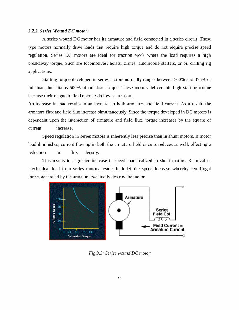
3.2.2. Series Wound DC motor:
A series wound DC motor has its armature and field connected in a series circuit. These
type motors normally drive loads that require high torque and do not require precise speed
regulation. Series DC motors are ideal for traction work where the load requires a high
breakaway torque. Such are locomotives, hoists, cranes, automobile starters, or oil drilling rig
applications.
Starting torque developed in series motors normally ranges between 300% and 375% of
full load, but attains 500% of full load torque. These motors deliver this high starting torque
because their magnetic field operates below saturation.
An increase in load results in an increase in both armature and field current. As a result, the
armature flux and field flux increase simultaneously. Since the torque developed in DC motors is
dependent upon the interaction of armature and field flux, torque increases by the square of
current increase.
Speed regulation in series motors is inherently less precise than in shunt motors. If motor
load diminishes, current flowing in both the armature field circuits reduces as well, effecting a
reduction in flux density.
This results in a greater increase in speed than realized in shunt motors. Removal of
mechanical load from series motors results in indefinite speed increase whereby centrifugal
forces generated by the armature eventually destroy the motor.
Fig 3.3: Series wound DC motor

22
3.2.3. Compound Wound DC motors:
Whenever an operation requires speed regulation characteristics unavailable in series or
shunt motors, compound wound motors perform well. With medial starting torque capability,
between 180 and 260% of full load, they deliver constant operating speeds under any percentage
of full loads. This characteristic is a result of placing part of the field circuit in series with that of
the armature. When under load, increased series winding current raises the level of field flux.
Enlarged field flux in compound wound motors yields greater reduction in speed than in a shunt
motor.
The compound wound DC motor comprises both series and shunt windings. The shunt
winding connects in parallel with armature and series windings. Some associated applications
include punch presses, shears, crushers, and reciprocating compressors.
Fig 3.4: Compound wound DC motor
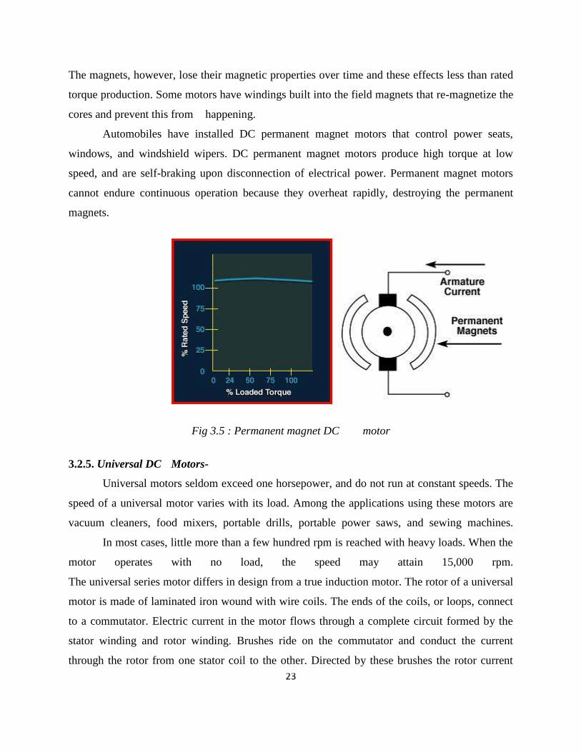
3.2.4. Permanent Magnet DC motor:
Permanent magnet motors are well fit for use where response time is a factor. Their speed
characteristics are similar to those of shunt wound motors. Built with a conventional armature,
they use permanent magnets rather than windings in the field section. DC power is supplied only
to the armature.
Permanent magnet motors are not expensive to operate since they require no field supply.
23
The magnets, however, lose their magnetic properties over time and these effects less than rated
torque production. Some motors have windings built into the field magnets that re-magnetize the
cores and prevent this from happening.
Automobiles have installed DC permanent magnet motors that control power seats,
windows, and windshield wipers. DC permanent magnet motors produce high torque at low
speed, and are self-braking upon disconnection of electrical power. Permanent magnet motors
cannot endure continuous operation because they overheat rapidly, destroying the permanent
magnets.
Fig 3.5 : Permanent magnet DC motor
3.2.5. Universal DC Motors-
Universal motors seldom exceed one horsepower, and do not run at constant speeds. The
speed of a universal motor varies with its load. Among the applications using these motors are
vacuum cleaners, food mixers, portable drills, portable power saws, and sewing machines.
In most cases, little more than a few hundred rpm is reached with heavy loads. When the
motor operates with no load, the speed may attain 15,000 rpm.
The universal series motor differs in design from a true induction motor. The rotor of a universal
motor is made of laminated iron wound with wire coils. The ends of the coils, or loops, connect
to a commutator. Electric current in the motor flows through a complete circuit formed by the
stator winding and rotor winding. Brushes ride on the commutator and conduct the current
through the rotor from one stator coil to the other. Directed by these brushes the rotor current

24
interacts with the magnetic field of the stator causing the rotor to turn. When the direction of
current flow changes in the stator, it changes in the rotor. Since the magnetic field is reversed,
the rotor continues to turn.
Universal motors have series wound rotor circuitry similar to that of DC motors. They
have high starting torque and high starting current. The name universal derives from the motor's
capability of operating on either AC or DC power sources.
Universal, variable speed motors slow down with increased loads. High horsepower-to-size ratio
is characteristic of their design. Due to the brush/commutator setup, universal motors require
more maintenance than other motor designs.
3.3. SPEED CONTROL METHODS OF DC MOTOR:
Fig 3.6: Speed control of a DC motor
Basically, there are three ways to vary the speed of DC motors:
1. With the use of mechanical gears to achieve the desired speed.
2. Reducing the motor voltage with a series resistor. However this is inefficient ( energy wasted
in resistor) and reduces torque. The current drawn by the motor increases as the load on the
motor increases. More current means a larger voltage drop across the series resistor and
therefore less voltage to the motor. The motor now tries to draw even more current resulting
in the motor “stalling”.

25
3. By applying the full voltage supply to the motor in bursts or pulses, eliminating the series
dropping effect. This is called the pulse width modulation (PWM). Shorter pulses means the
motor runs slowly, longer pulses make the motor run faster.
3.4. GEAR DC MOTOR:
A gear motor is a type of electrical motor. Like all electrical motors, it uses the
magnetism induced by an electrical current to rotate a rotor that is connected to a shaft. The
energy transferred from the rotor to the shaft is then used to power a connected device.
3.4.1 DESCRIPTION AND OPERATION:
In a gear motor, the energy output is used to turn a series of gears in an integrated gear
train. There are a number of different types of gear motors, but the most common are AC
(alternating current) and DC (direct current). DC gear motors are configured in many types and
sizes, including brushless and servo. They consist of a rotor and a permanent magnetic field
stator and an integral gearbox. They are used in variable speed and torque applications. Direct
motors are most common in industrial robots.
In a gear motor, the magnetic current (which can be produced by either permanent
magnets or electromagnets) turns gears that are either in a gear reduction unit or in an integrated
gear box. A second shaft is connected to these gears. The result is that the gears greatly increase
the amount of torque the motor is capable of producing while simultaneously slowing down the
motor's output speed. The motor will not need to draw as much current to function and will move
more slowly, but will provide greater torque. The gearbox increases the torque generating ability
of the motor while simultaneously reducing its output speed. The main advantage of a gearmotor
is that the driving shaft may be coupled directly to the driven shaft. Belts, pulleys, chains, or
additional gearing to step down motor speed are needed. Also, coupling or belting of a motor to a
separate speed-reducer unit is eliminated.
The reduction gear trains used in gear motors are designed to reduce the output speed
while increasing the torque. The increase in torque is inversely proportional to the reduction in
speed. Reduction gearing allows small electric motors to move large driven loads, although more

26
slowly than larger electric motors. Reduction gears consist of a small gear driving a larger gear.
There may be several sets of these reduction gear sets in a reduction gear box.
Finally its nothing but a small motor (ac induction, permanent magnet dc, or brushless
dc) designed specifically with an integral (not separable) gear reducer (gear head). The end
shield on the drive end of the motor is designed to provide a dual function. The side facing the
motor provides the armature/rotor bearing support and a sealing provision through which the
integral rotor or armature shaft pinion passes. The other side of the end shield provides multiple
bearing supports for the gearing itself, and a sealing and fastening provision for the gear housing.
Gear motors are complete motive force systems consisting of an electric motor and a
reduction gear train integrated into one easy-to-mount and easy-to-configure package. This
greatly reduces the complexity and cost of designing and constructing power tools, machines and
appliances calling for high torque at relatively low shaft speed or RPM. Gear motors allow the
use of economical low-horsepower motors to provide great motive force at low speed such as in
lifts, winches, medical tables, jacks and robotics. They can be large enough to lift a building or
small enough to drive a tiny clock.
Important performance specifications to consider when searching for gear motors include
shaft speed, continuous torque, continuous current, and continuous output power. The terminal
voltage is the design DC motor voltage. The continuous torque is the output torque capability of
the motor under constant running conditions. Continuous current is the maximum rated current
that can be supplied to the motor windings without overheating. Continuous output power is the
mechanical power provided by the motor output.
Speed Reduction
Sometimes the goal of using a gear motor is to reduce the rotating shaft speed of a motor
in the device being driven, such as in a small electric clock where the tiny synchronous motor
may be spinning at 1,200 rpm but is reduced to one rpm to drive the second hand, and further
reduced in the clock mechanism to drive the minute and hour hands. Here the amount of driving
force is irrelevant as long as it is sufficient to overcome the frictional effects of the clock
mechanism.
27
Torque Multiplication
Another goal achievable with a gear motor is to use a small motor to generate a very
large force albeit at a low speed. These applications include the lifting mechanisms on hospital
beds, power recliners, and heavy machine lifts where the great force at low speed is the goal.
Motor Varieties
Most industrial gear motors are AC-powered, fixed-speed devices, although there are
fixed-gear-ratio, variable-speed motors that provide a greater degree of control. DC gear motors
are used primarily in automotive applications such as power winches on trucks, windshield wiper
motors and power seat or power window motors.
3.4.2. APPLICATIONS:
Gear motors have a variety of successful applications. They are used in packaging and
labeling, case erectors, box taper, hot melt glue pumps, heat shrink tunnels, tape dispensers and
conveyor drives. They are also used in food processing industry. They are used in ice making
machines, weigh checking, baking machinery, meat slicing, cooker drive, and breading
equipment. In transport equipment they are used in wheelchairs, stair lifts, golf carts and pipeline
crawlers. In machine tools they are used in drill heads, rotary table drives, and hardness test. The
power can openers, garage door openers, stair lifts, rotisserie motors, timer cycle knobs on
washing machines, power drills, cake mixers and electromechanical clocks have in common is
that they all use various integrations of gear motors to derive a large force from a relatively small
electric motor at a manageable speed. In industry, gear motor applications in jacks, cranes, lifts,
clamping, robotics, conveyance and mixing are too numerous to count.
3.4.3. GEAR MOTOR BENEFITS:
Using the right sized motor and gear head combination for an application helps to
prolong gearmotor life and allows for optimum power management and power
utilization. Traditionally, design engineers oversized motors and gear heads to add
“safety factors” — Bodine “factory matched” gear motors consistently deliver rated
performance.

28
Quieter operation due to integral castings and integral pinion, ground on the armature
or rotor shaft. Fewer parts requiring assembly resulting in “near perfect” alignment of
the rotor, pinion and gear train.
Minimum risk of lubricant leakage, because of “O-ring” and lip seal construction. The
design can be more compact and the lubrication can be controlled better (for various
mounting configurations).
Gear motors eliminate the need for motor/gear head couplings and eliminate any
potential bearing alignment problems, common when a motor and gear head are
bolted together by an end-user (separable gear heads). Misalignment can result in
bearing failure due to fretting corrosion.
Separable motor and gear head solutions make more sense in larger integral
horsepower (>1 HP) applications. For example, when a 100-pound motor is mounted
to a 500-pound gear head.
3.5. SPECIFICATIONS OF DC MOTOR:
Fig 3.7: Gear DC motor
Table 3.1: Technical parameters
DC Micro Motor RF-500TB Technical Parameter
Model
Voltage No-Load At Maximum Efficiency Stall
Operating
Range Nominal
Speed Current Speed Current Torque Output
Power Torque Current
r/min A r/min A g.cm mN.m W g.cm mN.m A
RF-
500TB-
12560
1.5-6 6V 2700 0.020 2200 0.070 10 0.98 0.23 60 5.88 0.35
29
CHAPTER 4
CIRCUIT DESCRIPTION
30
CIRCUIT DESCRIPTION
4.1. CIRCUIT SCHEMATIC DIAGRAMS:
4.1.1. POWER SUPPLY CIRCUIT :
Fig 4.1: Power supply circuit
4.1.2. TRANSMITTER CIRCUIT:
Fig 4.2: Transmitter circuit
31
4.1.3. RECEIVER CIRCUIT:
Fig 4.3: Receiver circuit
4.1.4.FOUR RELAY CONTROL:
Fig: Four relay control

32
4.1.5. RELAY OPERATION:
Fig4.5: Relay operation
4.2. CIRCUIT OPERATION:
4.2.1. POWER SUPPLY SECTION:
Fig 4.6 : Block diagram of power supply
This section consists of the rectifier, filter and voltage regulator.
Rectifier:
The output from the transformer is fed to the rectifier. It converts A.C. into pulsating
D.C. The rectifier may be a half wave or a full wave rectifier. In this project, a bridge rectifier is
used because of its merits like good stability and full wave rectification.
Power supply to all sections
Step
down
T/F
Bridge
Rectifier
Filter
Circuit Regulator

33
Filter:
Capacitive filter is used in this project. It removes the ripples from the output of rectifier
and smoothens the D.C. Output received from this filter is constant until the mains voltage and
load is maintained constant. However, if either of the two is varied, D.C. voltage received at this
point changes. Therefore a regulator is applied at the output stage.
Voltage regulator:
As the name itself implies, it regulates the input applied to it. A voltage regulator is an
electrical regulator designed to automatically maintain a constant voltage level. In this project,
power supply of 5V and 12V are required. In order to obtain these voltage levels, 7805 is used.
The first number 78 represents positive supply and the numbers 05 represent the required output
voltage levels.
The power supply board initially has the 230v/9v transformer. Single phase ac supply of
230v is taken and given to the center tapped transformer. This transformer steps down the
voltage to 9v AC. The 9 volts AC voltage is converted to dc voltage by a bridge rectifier. The
terminals 1 and 3 are given to the transformer and terminals 2 and 4 give the dc voltage. The dc
voltage obtained is about 12v which contains ripples. So to remove such disturbances, ripples a
capacitor of 1000 micro farad , 35v rating is used which filters them out and gives pure 9v dc
supply. This capacitor also helps in maintaining a constant voltage input to the regulator. Then a
voltage regulator is used to get a 5v dc supply.
4.2.2. TRANSMITTER SECTION:
Fig 4.7: Block diagram of transmitter section
34
This section consists Encoder HT640, RF Transmitter 434 MHz, 9v battery, voltage
regulator, switches, and antenna.
The switches are placed at the encoder side. The encoder converts digital to analog signal
and is given to the transmitter. The transmitter sends this analog information through
electromagnetic waves (radio frequency) to the receiver section. The receiver section receives
this data through the receiver. The power supply to the transmitter section is a 9v battery. The
switches used here are manually operated. SW-1 represents forward direction control switch,
SW-2 represents reverse direction control switch, SW-3 represents high speed control switch,
SW-4 represents medium speed control switch. The switches used here are four-legged. \
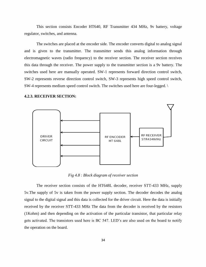
4.2.3. RECEIVER SECTION:
Fig 4.8 : Block diagram of receiver section
The receiver section consists of the HT648L decoder, receiver STT-433 MHz, supply
5v.The supply of 5v is taken from the power supply section. The decoder decodes the analog
signal to the digital signal and this data is collected for the driver circuit. Here the data is initially
received by the receiver STT-433 MHz The data from the decoder is received by the resistors
(1Kohm) and then depending on the activation of the particular transistor, that particular relay
gets activated. The transistors used here is BC 547. LED’s are also used on the board to notify
the operation on the board.
35
4.2.4. RELAY OPERATION:
Refer to fig 4.5 for the relay operation. In this the relay one and relay two have the direction
control over the DC motor whereas the relay 3 and relay 4 provide the speed control.
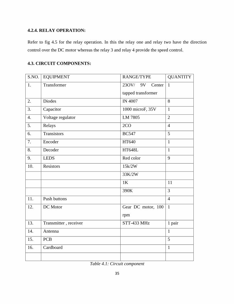
4.3. CIRCUIT COMPONENTS:
S.NO. EQUIPMENT RANGE/TYPE QUANTITY
1. Transformer 23OV/ 9V Center
tapped transformer
1
2. Diodes IN 4007 8
3. Capacitor 1000 microF, 35V 1
4. Voltage regulator LM 7805 2
5. Relays 2CO 4
6. Transistors BC547 5
7. Encoder HT640 1
8. Decoder HT648L 1
9. LEDS Red color 9
10. Resistors 15k/2W
33K/2W
1K 11
390K 3
11. Push buttons 4
12. DC Motor Gear DC motor, 100
rpm
1
13. Transmitter , receiver STT-433 MHz 1 pair
14. Antenna 1
15. PCB 5
16. Cardboard 1
Table 4.1: Circuit component
36
4.4. COMPONENT DESCRIPTIONS:
4.4.1. VOLTAGE REGULATOR:
The 78XX (sometimes LM78XX) is a family of self-contained fixed linear voltage
regulator integrated circuits. The 78xx family is commonly used in electronic circuits requiring a
regulated power supply due to their ease-of-use and low cost. For ICs within the family, the xx is
replaced with two digits, indicating the output voltage (for example, the 7805 has a 5 volt output,
while the 7812 produces 12 volts). The 78xx line are positive voltage regulators: they produce a
voltage that is positive relative to a common ground. There is a related line of 79xx devices
which are complementary negative voltage regulators. 78xx and 79xx ICs can be used in
combination to provide positive and negative supply voltages in the same circuit.
78xx ICs have three terminals and are commonly found in the TO220 form factor,
although smaller surface-mount and larger TO3 packages are available. These devices support an
input voltage anywhere from a couple of volts over the intended output voltage, up to a
maximum of 35 or 40 volts, and typically provide 1 or 1.5 amperes of current (though smaller or
larger packages may have a lower or higher current rating).
Advantages
7805 ICs do not require additional components to provide a constant, regulated source of
power, making them easy to use, as well as economical and efficient uses of space. Other
voltage regulators may require additional components to set the output voltage level, or to
assist in the regulation process. Some other designs (such as a switching power supply) may
need substantial engineering expertise to implement.
7805 ICs have built-in protection against a circuit drawing too much power. They have
protection against overheating and short-circuits, making them quite robust in most
applications. In some cases, the current-limiting features of the 7805 devices can provide
protection not only for the 7805 itself, but also for other parts of the circuit.

37
Disadvantages
The input voltage must always be higher than the output voltage by some minimum amount
(typically 2 volts). This can make these devices unsuitable for powering some devices from
certain types of power sources (for example, powering a circuit that requires 5 volts using 6-
volt batteries will not work using a 7805).
As they are based on a linear regulator design, the input current required is always the same
as the output current. As the input voltage must always be higher than the output voltage, this
means that the total power (voltage multiplied by current) going into the 78xx will be more
than the output power provided. The extra input power is dissipated as heat. This means both
that for some applications an adequate heat sink must be provided, and also that a (often
substantial) portion of the input power is wasted during the process, rendering them less
efficient than some other types of power supplies. When the input voltage is significantly
higher than the regulated output voltage (for example, powering a 7805 using a 24 volt power
source), this inefficiency can be a significant issue.
Even in larger packages, 78xx integrated circuits cannot supply as much power as many
designs which use discrete components, and are generally inappropriate for applications
requiring more than a few amperes of current.
4.4.2. TRANSMITTER:
The transmitter module used here is the RF TRANSMITTER STT-433MHz.
The STT-433 is ideal for remote control applications where low cost and longer range is
required.
The transmitter operates from a1.5-12V supply, making it ideal for battery-powered
applications.
The transmitter employs a SAW-stabilized oscillator, ensuring accurate frequency control for
best range performance.

38
The manufacturing-friendly SIP style package and low-cost make the STT-433 suitable for
high volume applications.
Features
433.92 MHz Frequency
Low Cost
1.5-12V operation
Small size
Fig 4.9: STT-433MHz Transmitter
Pin description:
GND -Transmitter ground. Connect to ground plane.
DATA -Digital data input. This input is CMOS compatible and should be driven with CMOS
level inputs.
VCC-Operating voltage for the transmitter. VCC should be bypassed with a .01uF ceramic
capacitor and filtered with a 4.7uF tantalum capacitor. Noise on the power supply will degrade
transmitter noise performance.
ANT- 50 ohm antenna output. The antenna port impedance affects output power and harmonic
emissions. Antenna can be single core wire of approximately 17cm length or PCB trace antenna.
39
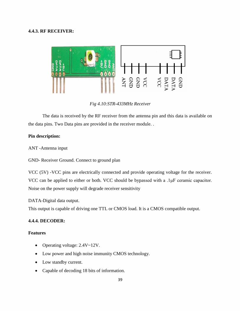
4.4.3. RF RECEIVER:
Fig 4.10:STR-433MHz Receiver
The data is received by the RF receiver from the antenna pin and this data is available on
the data pins. Two Data pins are provided in the receiver module. .
Pin description:
ANT -Antenna input
GND- Receiver Ground. Connect to ground plan
VCC (5V) -VCC pins are electrically connected and provide operating voltage for the receiver.
VCC can be applied to either or both. VCC should be bypassed with a .1μF ceramic capacitor.
Noise on the power supply will degrade receiver sensitivity
DATA-Digital data output.
This output is capable of driving one TTL or CMOS load. It is a CMOS compatible output.
4.4.4. DECODER:
Features
Operating voltage: 2.4V~12V.
Low power and high noise immunity CMOS technology.
Low standby current.
Capable of decoding 18 bits of information.

40
Pairs with HOLTEK’s 318 series of encoders.
8~18 address pins.
0~8 data pins.
Fig 4.11: HT648L Decoder
WORKING OF DECODER:
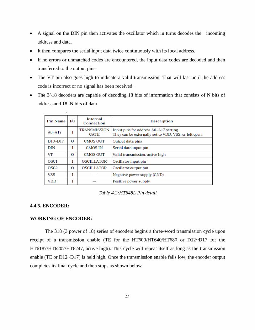
The 3^18 decoders are a series of CMOS LSIs for remote control system applications. They
are paired with the 3^18 series of encoders.
For proper operation, a pair of encoder/decoder pair with the same number of address and
data format should be selected.
The 3^18 series of decoders receives serial address and data from that series of encoders that
are transmitted by a carrier using an RF medium.
41
A signal on the DIN pin then activates the oscillator which in turns decodes the incoming
address and data.
It then compares the serial input data twice continuously with its local address.
If no errors or unmatched codes are encountered, the input data codes are decoded and then
transferred to the output pins.
The VT pin also goes high to indicate a valid transmission. That will last until the address
code is incorrect or no signal has been received.
The 3^18 decoders are capable of decoding 18 bits of information that consists of N bits of
address and 18–N bits of data.
Table 4.2:HT648L Pin detail
4.4.5. ENCODER:
WORKING OF ENCODER:
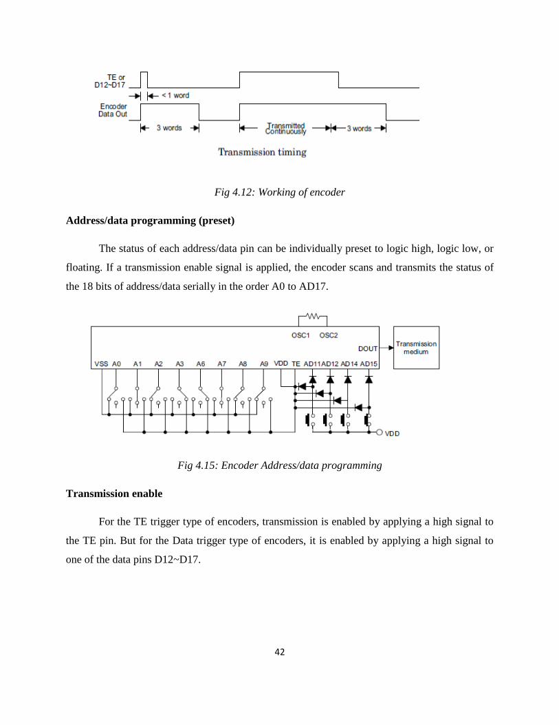
The 318 (3 power of 18) series of encoders begins a three-word transmission cycle upon
receipt of a transmission enable (TE for the HT600/HT640/HT680 or D12~D17 for the
HT6187/HT6207/HT6247, active high). This cycle will repeat itself as long as the transmission
enable (TE or D12~D17) is held high. Once the transmission enable falls low, the encoder output
completes its final cycle and then stops as shown below.
42
Fig 4.12: Working of encoder
Address/data programming (preset)
The status of each address/data pin can be individually preset to logic high, logic low, or
floating. If a transmission enable signal is applied, the encoder scans and transmits the status of
the 18 bits of address/data serially in the order A0 to AD17.
Fig 4.15: Encoder Address/data programming
Transmission enable
For the TE trigger type of encoders, transmission is enabled by applying a high signal to
the TE pin. But for the Data trigger type of encoders, it is enabled by applying a high signal to
one of the data pins D12~D17.
43
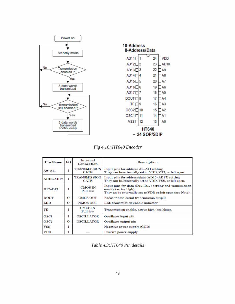
Fig 4.16: HT640 Encoder
Table 4.3:HT640 Pin details
44
4.4.6. RELAYS:
A relay is an electrically operated switch. Many relays use an electromagnet to operate a
switching mechanism mechanically, but other operating principles are also used. Relays are used
where it is necessary to control a circuit by a low-power signal (with complete electrical isolation
between control and controlled circuits), or where several circuits must be controlled by one
signal. The first relays were used in long distance telegraph circuits, repeating the signal coming
in from one circuit and re-transmitting it to another. Relays were used extensively in telephone
exchanges and early computers to perform logical operations.
A type of relay that can handle the high power required to directly control an electric
motor is called a contactor. Solid-state relays control power circuits with no moving parts,
instead using a semiconductor device to perform switching. Relays with calibrated operating
characteristics and sometimes multiple operating coils are used to protect electrical circuits from
overload or faults; in modern electric power systems these functions are performed by digital
instruments still called "protective relays".
BASIC DESIGN AND OPERATION:
A simple electromagnetic relay consists of a coil of wire surrounding a soft iron core, an
iron yoke which provides a low reluctance path for magnetic flux, a movable iron armature, and
one or more sets of contacts (there are two in the relay pictured). The armature is hinged to the
yoke and mechanically linked to one or more sets of moving contacts. It is held in place by a
spring so that when the relay is de-energized there is an air gap in the magnetic circuit. In this
condition, one of the two sets of contacts in the relay pictured is closed, and the other set is open.
Other relays may have more or fewer sets of contacts depending on their function. The relay in
the picture also has a wire connecting the armature to the yoke. This ensures continuity of the
circuit between the moving contacts on the armature, and the circuit track on the printed circuit
board (PCB) via the yoke, which is soldered to the PCB.
When an electric current is passed through the coil it generates a magnetic field that
attracts the armature and the consequent movement of the movable contact either makes or
45
breaks (depending upon construction) a connection with a fixed contact. If the set of contacts
was closed when the relay was de-energized, then the movement opens the contacts and breaks
the connection, and vice versa if the contacts were open. When the current to the coil is switched
off, the armature is returned by a force, approximately half as strong as the magnetic force, to its
relaxed position. Usually this force is provided by a spring, but gravity is also used commonly in
industrial motor starters. Most relays are manufactured to operate quickly. In a low-voltage
application this reduces noise; in a high voltage or current application it reduces arcing.
When the coil is energized with direct current, a diode is often placed across the coil to
dissipate the energy from the collapsing magnetic field at deactivation, which would otherwise
generate a voltage spike dangerous to semiconductor circuit components. Some automotive
relays include a diode inside the relay case. Alternatively, a contact protection network
consisting of a capacitor and resistor in series (snubber circuit) may absorb the surge. If the coil
is designed to be energized with alternating current (AC), a small copper "shading ring" can be
crimped to the end of the solenoid, creating a small out-of-phase current which increases the
minimum pull on the armature during the AC cycle.
A solid-state relay uses a thyristor or other solid-state switching device, activated by the
control signal, to switch the controlled load, instead of a solenoid. An opt coupler (a light-
emitting diode (LED) coupled with a photo transistor) can be used to isolate control and
controlled circuits.
TYPES OF RELAYS:
1. Latching Relay
Latching relays are also called impulse relays. They work in the bistable mode, and thus
have two relaxing states. They are also called keep relays or stay relays because as soon as the
current towards this relay is switched off, the relay continues the process that it was doing in the
last state. This can be achieved only with a solenoid which is operating in a ratchet and cam
mechanism. It can also be done by an over-centre spring mechanism or a permanent magnet
mechanism in which, when the coil is kept in the relaxed point, the over-centre spring holds the
46
armature and the contacts in the right spot. This can also be done with the help of a remanent
core. In the ratchet and cam method, power consumption occurs only for a particular time. Hence
it is more advantageous than the others.
2. Reed Relay
These types of relays have been given more importance in the contacts. In order to
protect them from atmospheric protection they are safely kept inside a vacuum or inert gas.
Though these types of relays have a very low switching current and voltage ratings, they are
famous for their switching speeds.
3. Polarized Relay
This type of relay has been given more importance on its sensitivity. These relays have
been used since the invention of telephones. They played very important roles in early telephone
exchanges and also in detecting telegraphic distortion. The sensitivity of these relays are very
easy to adjust as the armature of the relay is placed between the poles of a permanent magnet.
4. Buchholz Relay
This relay is actually used as a safety device. They are used for knowing the amount of
gas present in large oil-filled transformers. They are designed in such a way that they produce a
warning if it senses either the slow production of gas or fast production of gas in the transformer
oil.
5. Overload protection Relay
As the name implies, these relays are used to prevent the electric motors from damage by
over current and short circuits. For this the heating element is kept in series with the motor. Thus
when over heat occurs the bi-metallic strip connected to the motor heats up and in turn releases a
spring to operate the contacts of the relay.

47
6. Mercury Wetted Relay
This relay is almost similar to the reed relay explained earlier. The only difference is that
instead of inert gases, the contacts are wetted with mercury. This makes them more position
sensitive and also expensive. They have to be vertically mounted for any operation. They have
very low contact resistance and so can be used for timing applications. Due to these factors, this
relay is not used frequently.
7. Machine Tool Relay
This is one of the most famous industrial relay. They are mainly used for the controlling
of all kinds of machines. They have a number of contacts with easily replaceable coils. This
enables them to be easily converted from NO contact to NC contact. Many types of these relays
can easily be setup in a control panel. Though they are very useful in industrial applications, the
invention of PLC has made them farther away from industries.
8. Contactor Relay
This is one of the most heavy load relay ever used. They are mainly used in switching
electric motors. They have a wide range of current ratings from a few amps to hundreds. The
contacts of these relays are usually made with alloys containing a small percentage of silver. This
is done so as to avoid the hazardous effects of arcing. These type of relays are mainly
categorized in the rough use areas. So, they produce loud noises while operated and hence cannot
be used in places where noise is a problem.
9. Solid State relay
SSR relays, as its name implies are designed with the help of solid state components. As
they do not have any moving objects in their design they are known for their high reliability.
48
10. Solid State Contactor Relay
These relays combine both the features of solid state relays and contactor relays. As a
result they have a number of advantages. They have a very good heat sink and can be designed
for the correct on-off cycles. They are mainly controlled with the help of PLC, micro-processors
or microcontrollers.
SOME FEATURES OF RELAYS USED IN THIS PROJECT:
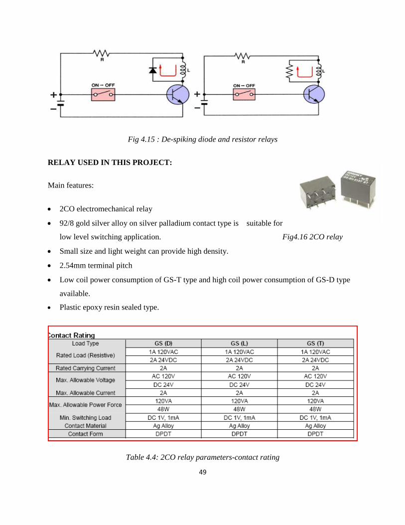
De-spiking Diode Relays
A diode in the reverse-biased position is connected in parallel with the relay coil. As
there is no flow of current due to such a connection, an open circuit of the relay will cause the
current to stop flowing through the coil. This will have effect on the magnetic field. The
magnetic field will be decreased instantly. This will cause the rise of an opposite voltage with
very high reverse polarity to be induced. This is mainly caused because of the magnetic lines of
force that cut the armature coil due to the open circuit. Thus the opposite voltage rises until the
diode reaches 0.7 volts. As soon as this cut-off voltage is achieved, the diode becomes forward-
biased. This causes a closed circuit in the relay, causing the entire voltage to pass through the
load. The current thus produced will be flowing through the circuit for a very long time. As soon
as the voltage is completely drained, this current flow will also stop.
De-spiking Resistor Relays
A resistor is almost efficient as that of a diode. It can not only suppress the voltage spikes
efficiently, but also allows the entire current to flow through it when the relay is in the on
position. Thus the current flow through it will also be very high. To reduce this, the value of the
resistance should be as high as 1 Kilo Ohm. But, as the value of the resistors increases the
voltage spiking capability of the relay decreases.
49
Fig 4.15 : De-spiking diode and resistor relays
RELAY USED IN THIS PROJECT:
Main features:
2CO electromechanical relay
92/8 gold silver alloy on silver palladium contact type is suitable for
low level switching application. Fig4.16 2CO relay
Small size and light weight can provide high density.
2.54mm terminal pitch
Low coil power consumption of GS-T type and high coil power consumption of GS-D type
available.
Plastic epoxy resin sealed type.
Table 4.4: 2CO relay parameters-contact rating

50
Applications:
Telecommunications, domestic appliances, office machine, audio equipment, remote control, etc.
Specifications:
1. Contact resistance….. 100mohm
2. Operate time ……GS-D 6msec , GS-T 8msec
3. Release time…… 4msec
4. Insulation resistance….. 100megaohm
5. Weight….. about 4.8 g
Fig 4.5: 2CO relay- coil specification
4.5. OPERATING PROCEDURE:
1. Initially the 230v AC supply is given to the center tapped transformer.
2. The bridge rectifier gives an output of 9v dc after filtering out the ripples.
3. The voltage regulator further gives 5v dc supply to the entire set-up.
4. A battery of 9v is attached to the transmitter section.

51
5. Suppose we want the motor to rotate in clockwise direction with high speed then the SW-1
and SW-3 is pressed manually.
6. We see that the transmitter transfers the data to the receiver section through electromagnetic
waves and the receiver obtains this data.
7. We see that the relay transistor 1 gets activated and so the relay one gets activated.
8. Suppose we want the motor to rotate in anti-clockwise direction, the SW-2 and SW-3 are
pressed.
9. In case we want the motor to rotate with a medium speed in clockwise direction then SW-1,
SW-3, SW-4 is pressed.
10. Accordingly we see the motor rotating in clockwise, anti-clockwise directions with medium
and high speeds.
Table 4.6: Relay operating procedure
RELAY1 RELAY2 RELAY3 RELAY4 MOTOR OPERATION
1 0 X X CLOCKWISE DIRECTION
0 1 X X ANTI-CLOCKWISE DIRECTION
0 0 X X OFF
1 1 X X OFF
X X 1 0 MEDIUM SPEED
X X 0 1 HIGH SPEED

52
CHAPTER 5
RESULTS AND APPLICATIONS
53
RESULTS AND APPLICATIONS
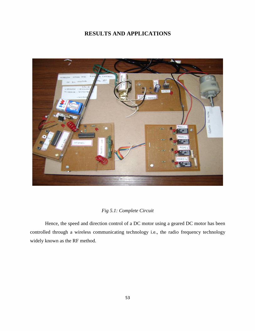
Fig 5.1: Complete Circuit
Hence, the speed and direction control of a DC motor using a geared DC motor has been
controlled through a wireless communicating technology i.e., the radio frequency technology
widely known as the RF method.
54
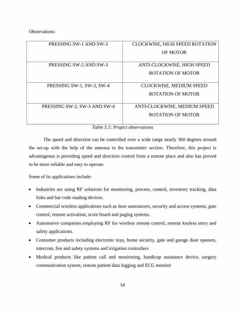
Observations:
PRESSING SW-1 AND SW-3 CLOCKWISE, HIGH SPEED ROTATION
OF MOTOR
PRESSING SW-2 AND SW-3 ANTI-CLOCKWISE, HIGH SPEED
ROTATION OF MOTOR
PRESSING SW-1, SW-3, SW-4 CLOCKWISE, MEDIUM SPEED
ROTATION OF MOTOR
PRESSING SW-2, SW-3 AND SW-4 ANTI-CLOCKWISE, MEDIUM SPEED
ROTATION OF MOTOR
Table 5.1: Project observations
The speed and direction can be controlled over a wide range nearly 360 degrees around
the set-up with the help of the antenna in the transmitter section. Therefore, this project is
advantageous is providing speed and direction control from a remote place and also has proved
to be more reliable and easy to operate.
Some of its applications include:
Industries are using RF solutions for monitoring, process, control, inventory tracking, data
links and bar code reading devices.
Commercial wireless applications such as door announcers, security and access systems, gate
control, remote activation, score board and paging systems.
Automotive companies employing RF for wireless remote control, remote keyless entry and
safety applications.
Consumer products including electronic toys, home security, gate and garage door openers,
intercom, fire and safety systems and irrigation controllers
Medical products like patient call and monitoring, handicap assistance device, surgery
communication system, remote patient data logging and ECG monitor
55
CHAPTER 6
CONCLUSION
56
CONCLUSION
The wireless communications have always proved a boon in this century. It has
been helpful is solving many intricate of satellite communication, telecommunications,
etc. Among its various methods, radio frequency technology has provided us with
accurate, easy, simpler, faster method of communication compared to the classical
approach. This project brings out one such wireless communication application. It shows
how a dc motor can be controlled wirelessly by the radio frequency technology.
Among all the speed control techniques, a DC geared motor speed is controlled by
using a simple relay driver circuit. Thus, we can obtain variable speeds with clockwise or
anti-clockwise direction of motor. For further use, a microcontroller can be used in this
set up. A potentiometer can also be included to have different speed levels. Tachometer
can also be developed to measure the speed using reed switch.

57
CHAPTER 7
REFERENCES
58
REFERENCES
WEBSITES:
1. http://www.circuitstoday.com/types-of-relays
2. www.howstuffworks.com
3. www.answers.com
4. www.radiotronix.com
5. www.WineYardProjects.com
6. http://gearmotorblog.wordpress.com/2009/08/13/what-is-a-gearmotor/
7. http://kontakt-t.narod.ru/catalog/file/relay_goodsky/en_GS.pdf
MAGAZINES:
1. Electronics for you magazine
2. Electrikindia magazine
3. Go Wireless magazine
BOOKS:
1. Radio Frequency Applications By Morris Hamington
2. Working with Radio Frequency By Cruis Leanardo