wirelessusb ls development kit user's guide
TRANSCRIPT

WirelessUSB™ LS Development Kit User’s Guide 1. Introduction This User’s Guide provides instructions to properly assemble the WirelessUSB LS DVK com-ponents, to demonstrate the functionality of WirelessUSB LS Radio System on a Chip, and to give instruction about how to develop new WirelessUSB LS peripherals and bridges. The WirelessUSB™ LS Development Kit (DVK) includes the following hardware components:
Qty Item 1 WirelessUSB DVK Platform Board for Wireless Peripherals (121-07500) 1 WirelessUSB DVK Platform Board for USB HID Bridge (121-07501) 2 WirelessUSB LS Single Antenna Radio Modules (PDC-9163) 1 WirelessUSB LS Listener Tool 1 AC/DC Power Adapter 3 AA Batteries 1 USB Cable 1 Serial Cable 1 Kit CD-ROM 1 Chip Kit, including:
PSoC Adapter Board preprogrammed for Mouse (“M”) PSoC Adapter Board preprogrammed for Keyboard (“KB”) PSoC Adapter Board preprogrammed for Gamepad (“GP”) enCoRe chip preprogrammed for Keyboard/Mouse Combo (“KB/M”) enCoRe chip preprogrammed for Gamepad (“GP”) Qty 2 blank enCoRe chips for customer development 10k-ohm carbon film resistor for HID bridge development
Table 1: Kit Contents Referenced in this User’s Guide
Figure 1: The WirelessUSB Development Kit Contents
Cypress Semiconductor Corporation • 3901 North First Street • San Jose • CA 95134 • 408-943-2600

2. Quick Start Using the Preprogrammed Chips The following instructions show how to used the preprogrammed Cypress MicroSystems PSoC™ and Cypress enCoRe™ chips with the WirelessUSB LS Radio System on a Chip to demonstrate a wireless mouse, keyboard, and gamepad. These preprogrammed chips are configured as follows:
Feature Wireless Mouse (M)
Wireless Keyboard (K)
Wireless Gamepad (GP)
Bind Automatic Automatic Automatic Data Rate 64 kbps 64 kbps 64 kbps
Directionality 2-way 2-way 2-way USB Bridge support
(enCoRe) KB/M Combo KB/M Combo GP
Table 2: Configuration of Preprogrammed PSoC Adapters in Kit Some minor assembly is required to demonstrate the functionality of the keyboard, mouse, and gamepad. The instructions below show how to correctly configure the platform boards and operate each of the devices.
WirelessUSB LS Mouse To configure this development kit to model a mouse, follow these steps:
1. On the peripheral DVK Platform Board (assembly 121-07500) verify that sockets U2A and U2B are not loaded and that U3 is loaded with the PSoC Adapter Board (PDC-9179) labeled “M”; See , Note 1. Figure 2
2. On the USB HID Bridge DVK Platform Board (assembly 121-07501) verify that sockets U2A and U3 are not loaded and that U2B is loaded with the Cypress enCoRe chip labeled “KB/M”.
3. Plug the LS Radio Module (PDC-9163) into the Radio Module Socket (P1) on each of the DVK Platform Boards. Note that the LS Radio faces toward the DVK Platform Board as shown below in Figure 2, Note 2.
4. On the peripheral DVK Platform Board (assembly 121-07500), verify that PWR_SEL jumper (J2) is using the EXT/BATT position (shunt connecting pins 2-3; see Figure 2, Note 3). Connect the AC/DC power adapter to J5 or insert the AA batteries into battery holder. Upon receiving power at least one of the LEDs (D0-D7) will light.
5. On the USB HID Bridge DVK Platform Board (assembly 121-07501), verify that the PWR_SEL jumper (J2) is using the VBUS position (shunt connecting pins 1-2). Upon receiving power from VBUS at least on of the LEDs (D0-D7) will light or flash.
6. Plug the USB HID Bridge platform board into the host PC’s USB port using the provided USB cable. If this is the first time the LS Bridge is connected to the host PC, the host PC will prompt for a driver, twice. The LS Bridge is preprogrammed to support one wireless mouse and one wireless keyboard simultaneously. The host PC should automatically load the HID drivers, but if it does not, browse to the HID driver location.
WirelessUSB LS Development Kit User’s Guide v1.4 Page 2 of 13

7. Press the BIND button on the USB HID Bridge and then on the peripheral platform board. The USB HID Bridge and the peripheral will automatically select a channel and PN Code and bind.
8. Congratulations! You now have a wireless mouse using the WirelessUSB LS Radio System on a Chip. Use the following joysticks and buttons to control the mouse from the peripheral DVK Platform Board:
Component Function
Left Joystick Mouse coordinates (X-Y position) Right Joystick Scroll wheel Right Joystick Button Middle mouse button Num Lock Left mouse button “–” (Button S8) Right mouse button
Table 3: Mouse Button Assignments on DVK Platform Board
Moving the joysticks or pressing the keypad buttons on the DVK Platform Board before the mouse is bound to the bridge may result in a mouse right-click event after bind is complete. Please see the WirelessUSB LS Keyboard / Mouse Reference Design Kit (CY4632) for production-ready keyboard and mouse designs. On the LS USB HID Bridge, LED D9 next to the BIND button indicates wireless activity. The CONNECT button (S21) is not used for USB HID bridges and WirelessUSB LS peripherals.
WirelessUSB LS Keyboard To configure this development kit to model a keyboard, follow these steps:
1. On the peripheral DVK Platform Board (assembly 121-07500) verify that sockets U2A and U2B are not loaded and that U3 is loaded with the PSoC Adapter Board (PDC-9179) labeled “K”.
2. On the USB HID Bridge DVK Platform Board (assembly 121-07501) verify that sockets U2A and U3 are not loaded and that U2B is loaded with the Cypress enCoRe chip labeled “KB/M”.
3. Follow steps 3-7 from the section titled “WirelessUSB LS Mouse”. 4. Congratulations! You now have a wireless keyboard using the WirelessUSB LS Radio
System on a Chip. Use the keypad area to transmit keys to the host PC from the peripheral DVK Platform Board. The following buttons have the functions shown below:
Component Function Keypad Buttons Keypad from 101-key keyboard Left Joystick Button Home Right Joystick Button End Spare Delete
Table 4: Keyboard Button Assignments on DVK Platform Board
WirelessUSB LS Development Kit User’s Guide v1.4 Page 3 of 13
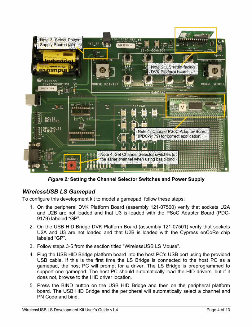
Note 2: LS radio facing DVK Platform board
Note 3: Select Power Supply Source (J2)
Note 1: Choose PSoC Adapter Board (PDC-9179) for correct application
Note 4: Set Channel Selector switches to the same channel when using basic bind
Figure 2: Setting the Channel Selector Switches and Power Supply
WirelessUSB LS Gamepad To configure this development kit to model a gamepad, follow these steps:
1. On the peripheral DVK Platform Board (assembly 121-07500) verify that sockets U2A and U2B are not loaded and that U3 is loaded with the PSoC Adapter Board (PDC-9179) labeled “GP”.
2. On the USB HID Bridge DVK Platform Board (assembly 121-07501) verify that sockets U2A and U3 are not loaded and that U2B is loaded with the Cypress enCoRe chip labeled “GP”.
3. Follow steps 3-5 from the section titled “WirelessUSB LS Mouse”. 4. Plug the USB HID Bridge platform board into the host PC’s USB port using the provided
USB cable. If this is the first time the LS Bridge is connected to the host PC as a gamepad, the host PC will prompt for a driver. The LS Bridge is preprogrammed to support one gamepad. The host PC should automatically load the HID drivers, but if it does not, browse to the HID driver location.
5. Press the BIND button on the USB HID Bridge and then on the peripheral platform board. The USB HID Bridge and the peripheral will automatically select a channel and PN Code and bind.
WirelessUSB LS Development Kit User’s Guide v1.4 Page 4 of 13

6. Congratulations! You now have a wireless gamepad using the WirelessUSB LS Radio System on a Chip. Use the following joysticks, buttons, and potentiometers to control the gamepad from the peripheral DVK Platform Board:
Component Function Left Joystick X and Y Axes Right Joystick Z Rotation and Slider Left Joystick Button Button 1 Right Joystick Button Button 2 Buttons 2, 4, 6, 8 Point of View (POV) Hat POT A X Rotation POT B Z Axis
Table 5: Gamepad Button Assignments on DVK Platform Board
The DVK Platform Board demonstrates gamepad functionality using potentiometers (POT A – POT H) that do not have Return-to-Zero (RTZ) capabilities. At power-on the values of these potentiometers are not sent until a change is detected in the gamepad’s inputs (e.g. joystick, button, or potentiometer).
3. HID Configurations The WirelessUSB LS DVK firmware is written so that it can be easily reconfigured and compiled to be a keyboard, mouse, gamepad, or general serial device. The firmware release supports multiple bind processes and data rate options, and 1-way or 2-way communication.
shows the valid HID configurations available (not shaded). The configurations of the preprogrammed chips in this kit are marked in the table. Table 6
Table 6: Valid HID Configurations (P = Peripheral, B = Bridge)
MOUSE KEYBOARD KB/M
COMBO GAMEPAD GENERAL GENERAL MASTER
Bind Data Rate P B P B B P B P P
16 kbps 32 kbps Basic 64 kbps 16 kbps 32 kbps
1-WAY
Semi 64 kbps 16 kbps 32 kbps Basic 64 kbps 16 kbps 32 kbps
2-WAY
Auto 64 kbps M K KB/M GP GP
The rest of this section explains how to reconfigure a USB HID Bridge and WirelessUSB LS Peripheral and describes each HID device type, data rate, and bind option available.
WirelessUSB LS Development Kit User’s Guide v1.4 Page 5 of 13
Reconfiguring the USB HID Bridge (Using enCoRe) To change the configuration of the USB HID Bridge, open the config.inc file in the \Firmware\enCoRe folder in the supplied CD-ROM shown in the following example and set the defined preprocessor definitions as desired: ;***** DEVICE TYPE ***** DEFINE DEVICE_MOUSE ;DEFINE DEVICE_KEYBOARD ;DEFINE DEVICE_KB_MOUSE_COMBO ;DEFINE DEVICE_GAMEPAD ;***** DATA RATE ***** ;DEFINE DATA_RATE_16 ;DEFINE DATA_RATE_32 DEFINE DATA_RATE_64 ;***** BIND PROCEDURE ***** ;DEFINE BIND_BASIC_ONE_WAY ;DEFINE BIND_BASIC_TWO_WAY ;DEFINE BIND_SEMI DEFINE BIND_AUTO
Reconfiguring the WirelessUSB LS Peripheral (Using PSoC) To change the configuration of the platform board, open the ls_config.h file in the \Firmware\PSoC\<Device Type> folder in the supplied CD-ROM. Each device type (i.e. keyboard, mouse, gamepad, etc) has its own folder. Set the defined preprocessor definitions shown in the following example: // PROTOCOL PARAMETERS //#define DATA_RATE_16 //#define DATA_RATE_32 #define DATA_RATE_64 #define TWO_WAY // comment out for One Way protocol // BIND SCHEMES //#define BIND_BASIC //#define BIND_SEMI #define BIND_AUTO
Note: There may be more protocol parameters listed in ls_config.h than shown in this example. Please see the WirelessUSB LS DVK Firmware Design Notes for details on each parameter.
Device Types
Mouse The mouse application uses the joysticks and buttons on the peripheral DVK Platform Board to emulate a 3-button scroll wheel mouse. The mouse button assignments are listed in on page 3.
Table 3
WirelessUSB LS Development Kit User’s Guide v1.4 Page 6 of 13

Keyboard The keyboard application uses the buttons on the peripheral DVK Platform Board to emulate the keypad of a typical 101-key keyboard. The keyboard button assignments are listed in Table 4 on page 3.
Gamepad The gamepad application uses the joysticks, potentiometers (pots) and buttons on the peripheral DVK Platform Board to emulate a PC gamepad. The gamepad button assignments are listed in Table 5 on page 5.
Keyboard/Mouse Combo The Keyboard/Mouse Combo application uses the standard Mouse and Keyboard applications on peripheral DVK Platform Boards, but uses the Keyboard/Mouse Combo application on the USB HID Bridge. The Keyboard/Mouse Combo HID Bridge receives data from keyboard and mouse peripherals simultaneously as described in WirelessUSB LS 2-Way HID Systems.
General and General Master The general application uses the RS-232 serial ports on the platform boards to create a simple wireless serial link between two platform boards. Each byte received via the RS-232 port is transmitted over the WirelessUSB link and each byte received via the WirelessUSB link is in turn sent to the RS-232 port. The protocol supports variable-length packets and can transmit and receive up to 18 bytes of data per packet. The serial port settings between the serial terminal (like HyperTerminal) and the DVK Platform board are 115.2 kbps, 8 data bits, no parity, 1 stop bit, no flow control (115200, 8, N, 1, none). The General device type may be used for two serial peripherals using basic bind. If automatic bind is desired then one serial peripheral must have the device type of General and the other the device type of General Master. The General Master device type includes the master side of the automatic bind logic. Both devices must specify the same protocol option (basic or automatic) to work correctly. When using the General or General Master device types remove the enCoRe chip from the USB Bridge. This kit does not include preprogrammed PSoC chips for these device types, so it will be necessary to recompile the PSoC firmware and program the PSoC chips (see Compiling on page 11 for instructions).
Protocol Options
1-Way vs. 2-Way In the 1-way protocol the peripheral DVK Platform Board transmits data while the WirelessUSB LS HID Bridge receives data. Because the wireless peripheral cannot guarantee that the USB HID Bridge correctly receives data, the peripherals may transmit multiple copies of the same packet in order to ensure the USB HID Bridge receives the data correctly. If using the 1-way protocol comment out #define TWO_WAY in ls_config.h. In 2-way mode all devices are configured as transceivers allowing the USB HID Bridge to respond to the wireless peripheral. The 2-way protocol uses ACK packets to acknowledge the correct reception of DATA packets. This increases the reliability of data transmissions. The 2-
WirelessUSB LS Development Kit User’s Guide v1.4 Page 7 of 13
way protocol also allows the USB HID Bridge to send back-channel DATA (and ACK/DATA) packets to the wireless peripheral for complete 2-way communication. If using the 2-way protocol verify that #define TWO_WAY is not commented in ls_config.h.
Basic Bind (1-Way or 2-Way) Basic bind uses the 16-position rotary channel selector switch to change channels. The value of the switch is multiplied by 5 to achieve a logical channel range of 0-75. The PN Code is static and is defined by the DEFAULT_PN_CODE definition in ls_config.h and config.inc.
Semi-Automatic Bind (1-Way Only) Semi-automatic bind uses the Bind Button on both DVK Platform Boards (located to the left of the radio module) to initiate a semi-automatic bind procedure as described in WirelessUSB LS 1-Way HID Networks. This bind procedure allows the wireless peripheral to dynamically choose a channel and PN Code and then notify the USB HID Bridge of the new channel and PN Code.
Automatic Bind (2-Way Only) Automatic Bind uses the Bind Button on both DVK Platform Board (located to the left of the radio module) to initiate an automatic bind procedure as described in WirelessUSB LS 2-Way HID Systems. This bind procedure binds the wireless peripheral to the USB HID Bridge. After the wireless peripheral is bound it is able to establish a connection to the USB HID Bridge. If the connection receives excessive interference the USB HID Bridge can switch channels until a quiet channel (i.e. low interference level) is found and notify the wireless peripheral. Automatic Bind is the most complex of the WirelessUSB LS bind options, but it is also the most powerful and requires the least amount of user intervention. For more information on automatic bind see WirelessUSB LS 2-Way HID Systems.
Data Rates There are three data rates available in WirelessUSB LS. This section gives a short description of each data rate. See WirelessUSB LS Theory of Operation application note for more details.
16 kbps The 16 kbps data rate uses 64chips/bit PN Codes providing higher processing gain and thus longer range than 32 and 64 kbps data rates. It is ideal for long range, high data integrity, low data rate applications. The maximum data throughput for this data rate is 15.7 kbps.
32 kbps The 32 kbps data rate uses 32chips/bit PN Codes, which requires less time to transmit each data bit than 16 kbps data rate, but the range is slightly reduced compared to the 16 kbps data rate. The 32 kbps data rate allows the USB HID Bridge to load two PN Codes into the radio at the same time, allowing the bridge to communicate with two devices. The maximum data throughput for this data rate is 31.25 kbps.
64 kbps The 64 kbps data rate uses 32chips/bit PN Codes just like the 32 kbps data rate does, but instead of using a single PN Code for to transmit data it uses two 32chips/bit PN Codes allowing two data bits to be represented by the transmission of a single bit. The 64 kbps data rate has the same range as the 32 kbps data rate. It is ideal for short range, moderate data rate applications. The maximum data throughput for this data rate is 62.5 kbps.
WirelessUSB LS Development Kit User’s Guide v1.4 Page 8 of 13

4. Firmware Customization and Development The Cypress development kits required to develop peripheral and USB HID Bridge firmware are shown in below. Technical details regarding these development kits are discussed in their associated development kit user’s guides. These kits are available for order from the Cypress Online Store at http://www.onfulfillment.com/cypressstore/.
Table 7
Table 7: PSoC and enCoRe Development Kits
Development
Type Chip DVK Part Number DVK Description CY3654 enCoRe Platform Board CY3654-P05 enCoRe Personality Board
WirelessUSB LS USB HID
Bridge
Cypress enCoRe (CY7C63743)
CYASM v1.96 Included in this kit’s CD-ROM CY3205-DK PSoC™ Microcontroller Basic Development Kit CY3206-PI PDIP Pod Kit (for 48-PDIP foot) CY3207-POD PSoC ICE Pod Kit for CY8C27X Device Family CY3202-C PSoC Designer™ C Compiler
WirelessUSB LS Peripheral
Cypress MicroSystems PSoC (CY8C27643-24PVI) adapted to 48-PDIP
socket PSoC Designer v4.1 Included in this kit’s CD-ROM
USB HID Bridge Development (Using enCoRe)
Development The development kit for the enCoRe chip (CY7C63743) is composed of two pieces – the CY3654 and CY3654-P05. The CY3654 emulates the enCoRe’s M8 core, and the CY3654-P05 emulates the enCoRe’s specifics. More information about the CY3654 + CY3654-P05 development kit can be found at www.cypress.com (Click on the USB Low-Speed Peripherals link Developer Kits CY3654 + CY3654-P05). Refer to for details on how to connect the CY3654 Development Kit to the WirelessUSB LS USB HID Bridge. Because the WirelessUSB LS Development Kit uses a feature supported in the enCoRe chip that is not supported by its development kit, a 10k-ohm pull-down resistor (included in the kit) is required to connect pins 24 and 36 on the PSoC socket (U3). This 10k-ohm resistor is not required when a programmed enCoRe chip is in socket U2B.
Figure 3
WirelessUSB LS Development Kit User’s Guide v1.4 Page 9 of 13
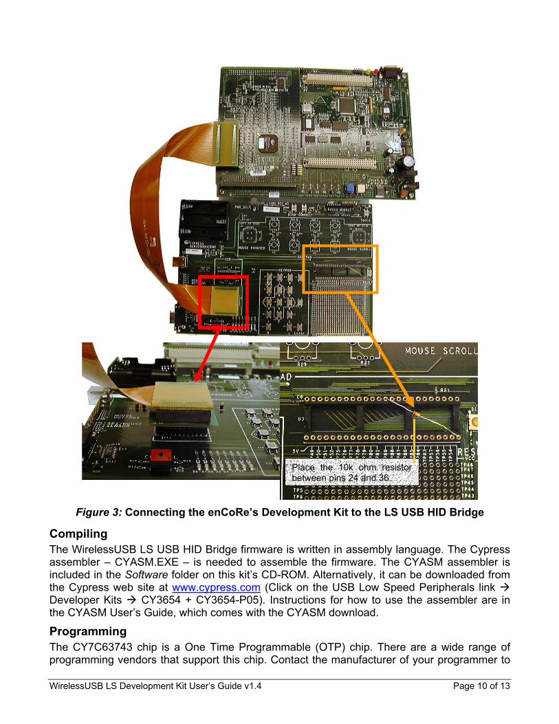
Place the 10k ohm resistor between pins 24 and 36.
Figure 3: Connecting the enCoRe’s Development Kit to the LS USB HID Bridge
Compiling The WirelessUSB LS USB HID Bridge firmware is written in assembly language. The Cypress assembler – CYASM.EXE – is needed to assemble the firmware. The CYASM assembler is included in the Software folder on this kit’s CD-ROM. Alternatively, it can be downloaded from the Cypress web site at www.cypress.com (Click on the USB Low Speed Peripherals link Developer Kits CY3654 + CY3654-P05). Instructions for how to use the assembler are in the CYASM User’s Guide, which comes with the CYASM download.
Programming The CY7C63743 chip is a One Time Programmable (OTP) chip. There are a wide range of programming vendors that support this chip. Contact the manufacturer of your programmer to
WirelessUSB LS Development Kit User’s Guide v1.4 Page 10 of 13

learn about its capability. The Hi-Lo programmer can be used to program the CY7C63743. More information on the Hi-Lo programmer can be found at www.cypress.com.
WirelessUSB LS Peripheral Development (Using PSoC)
Development Information regarding the PSoC development environment can be found at Cypress MicroSystems’ website at www.cypressmicro.com. The PSoC Microcontroller Basic Development Kit (CY3205-DK) with the PSoC ICE CY8C27X Device Family Pod Kit (CY3207-POD) provides support for development and debugging (with breakpoint support) of PSoC application code. The PDIP Pod Kit (CY3206-PI) provides the 48-PDIP package compatible with the DVK Platform Board (socket U3). Figure 4
Figure 4: Connecting the PSoC Development Kit to the DVK Platform Board
shows how to connect the Cypress MicroSystems PSoC Development Kit to the DVK Platform Board for firmware development and debugging.
Compiling The wireless peripheral firmware is written in C and is designed to be portable. PSoC Designer 4.1 and the PSoC Designer C Compiler (CY3202-C) are required to compile the firmware. Refer to the PSoC Development Kit User’s Guide for technical information. A copy of the PSoC Designer 4.1 is included on this kit’s CD-ROM in the Software folder. Additional instructions on
WirelessUSB LS Development Kit User’s Guide v1.4 Page 11 of 13
compiling the firmware are found in the WirelessUSB LS Development Kit Firmware Design Notes document provided on this kit’s CD-ROM.
Programming The PSoC Basic Development Kit includes programming capabilities. The PSoC Adapter Board (PDC-9179) is programmable through the 5-pin ISSP header (J2). Refer to the PSoC Development Kit User’s Guide for how to program the PSoC.
5. Debugging the WirelessUSB LS Protocol
Serial Port Debugger WirelessUSB LS peripherals (i.e. keyboards, mice, or gamepads) can be compiled to provide useful diagnostic information through the serial port for debugging devices under development. To enable serial debugging:
1. Uncomment #define DEBUG in ls_config.h.
2. Recompile the peripheral code using Rebuild All. 3. Program or debug the WirelessUSB LS peripheral. 4. Connect the serial cable to the peripheral platform board and to the serial port on a PC. 5. Launch a terminal application on the PC. Select the correct COM port. Change the port
settings to 115,200 baud, 8 bits, no parity, and 1 stop bit, no flow control (115200, 8, N, 1, none).
6. The debug data should be displayed on the terminal application. Note: Excessive debug data may change the timing of the PSoC and therefore may induce some errors in data transmitted to the USB HID Bridge.
WirelessUSB Listener Tool To assist developers in debugging WirelessUSB LS bridges and peripherals, Cypress has provided the WirelessUSB Listener Tool as a feature of this development kit. This device has been used by Cypress engineers to assist in developing and debugging the WirelessUSB LS protocols defined in the WirelessUSB LS 2-Way HID Systems and WirelessUSB LS 1-Way HID Networks application notes. The Listener Tool works by listening to WirelessUSB LS traffic on a given channel and PN code. It passes the captured packets to a host computer through a full-speed USB connection. The Listener Tool software decodes the captured data into packets and displays it. See the WirelessUSB Listener Tool Getting Started Guide on the CD-ROM for installation instructions. Further information is provided in the included help file, ListenLS.chm.
WirelessUSB LS Development Kit User’s Guide v1.4 Page 12 of 13

Figure 5: WirelessUSB Listener Tool
6. Power Management The WirelessUSB LS Development Kit provides a framework for power management within its source code. To maximize portability to other platform architectures the firmware does not implement the power-saving features of the PSoC chip. Therefore this DVK is not suitable for making assessments of power consumption or battery life. It is recommended that the DVK Platform Board remain plugged in during long periods of use. The WirelessUSB LS Keyboard / Mouse Reference Design Kit (CY4632) provides production-ready keyboard, mouse, and USB HID bridge designs that implement full power management support.
Revision Date Changes 1.0 April 14, 2003 Initial Release 1.1 June 27, 2003 Update for firmware upgrade 1.2 August 28, 2003 Update for engineering samples of WirelessUSB LS Radio SoC 1.3 November 12, 2003 Update for release of WirelessUSB LS Development Kit 1.4 March 30, 2004 Update for release of WirelessUSB LS Development Kit v1.5
WirelessUSB and enCoRe are trademarks of Cypress Semiconductor. PSoC and “PSoC Designer” are trademarks of Cypress MicroSystems, a subsidiary of Cypress Semiconductor.
WirelessUSB LS Development Kit User’s Guide v1.4 Page 13 of 13