wiring a tortoise switch machine for the mainline - lamrs siding/members/wiring a tortoise machine,...
TRANSCRIPT

Los Angeles Model Railroad Society
Wiring A Tortoise Switch Machine for the Mainline
Ira Abramowitz 2/27/2010

2
1 INTRODUCTION ............................................................................................................................3
1.1 LET’S START .................................................................................................................................3
2 MECHANICAL MOUNTING .............................................................................................................4
2.1 MECHANICAL MOUNTING OPTIONS ...................................................................................................4
2.2 TURNOUT CRANKS .........................................................................................................................4
2.3 MECHANICAL MOUNTING ................................................................................................................4
3 POWER THE TORTOISE ..................................................................................................................6
3.1 IMPORTANT NOTE FOR CONNECTING TO TORTOISE ................................................................................6
3.2 WIRE GAUGE ................................................................................................................................6
3.3 MARK ONE SIDE OF THE TORTOISE AND CONNECTOR .............................................................................6
3.4 PIN NUMBERING ...........................................................................................................................6
3.5 WIRE COLORS ...............................................................................................................................6
3.6 BRING POWER FROM SE8C TO TORTOISE ............................................................................................7
3.7 TEST THE PIN 1 AND 8 POLARITY .......................................................................................................7
3.8 LED MODULE ...............................................................................................................................7
3.9 INSTALLATION OF LED INTO FASCIA ....................................................................................................8
3.10 WIRE THE FROG...........................................................................................................................8
3.11 CHECK THE FROG WIRING ..............................................................................................................9
3.12 FINAL TEST .................................................................................................................................9
APPENDIX 1, TORTOISE WIRE BENDING GUIDE ................................................................................. 10
APPENDIX 2, PRIMARY LED MODULE ................................................................................................ 11
APPENDIX 3, POWER MODULE ......................................................................................................... 12
APPENDIX 4, ALTERNATE LED MODULE ............................................................................................. 13
APPENDIX 5, ALTERNATE POWER MODULE ....................................................................................... 14
3
1 Introduction You are starting a great adventure.
You will be well prepared if you first read these directions in their entirety.
If you use Stan’s mount (see later), build the LED module described in Appendix 2.
Build the Power Module, Appendix 3, and then pre-wire the Tortoise connector with Power and Frog
connections.
An alternate LED and Power Module are described in Appendices 4 and 5. These are for use with the
Tortoise Remote Mount.
1.1 Let’s Start You are replacing an existing mainline switch machine whose electrical connections are proper, but
whose mechanical elements are out-of-whack. A mainline machine has several characteristics:
1. It may be operated by a fascia-mounted push button
2. It is addressable by a DT400-402 using the address shown on the fascia
3. It is powered by an SE8C
4. It has a powered frog
Confirm that this is true.
Switch machines in the yard may be replaced by similar techniques, but at present, these machines are
powered from a DC power supply. Here, the polarity of the DC to the machine is switched by a panel-
mounted DPDT toggle switch. Not all frogs are power switched in yards.
1.1.1 Remove the Existing Switch Master Switch Machine
1.1.1.1 Switch Motor Power
Turn off Track power. Then identify and mark the power leads to the existing Switch Master (black
cylinder) machine. These are the two leads (from the SE8C for mainline turnouts) that attach to solder
terminals at the bottom of the motor from the SE8C. Usually, there are voltage-dropping resistors in
series with one or both of the leads. These resistors are no longer needed.
1.1.1.2 Frog Power
Frog power comes from the stock rails of the turnout (the fixed outside rails). We are going to identify
these leads and remove them from the existing motor.
The motor is supported from the layout by two screws, each passes through the motor and a plastic
stud. Now, while holding the motor, detach it carefully from the layout. Three leads are still connected
to micro-switches at the top of the motor. These leads are used to power the frog. Carefully de-solder or
cut these leads at the terminals of the micro-switch. The motor and mounting hardware are no longer
needed.

4
Identify and mark the two leads that from the stock rails, which power the frog, and the lead that goes
to the frog itself. These were attached to the two micro-switches. Note, that one of these leads also is
attached to the fascia LED. This branch to the LED is no longer needed.
2 Mechanical Mounting
2.1 Mechanical Mounting Options Tortoise machines may be mounted by many methods and in various configurations. Specifically the
voltage polarity (between Tortoise pins 1 and 8) to drive a Tortoise to the through, “t”, (or diverging)
route is difficult for me to figure out at this stage of the installation. I play it loose and am prepared to
swap the wires.
Similarly, I would not install the LED into the fascia until instructed in paragraph 3.9 (or else be prepared
to swap wires here too)
Lastly, be prepared to swap the feed wires that power the frog.
2.2 Turnout Cranks If new cranks are needed, use 0.032-inch piano wire (K & S part #1143) for the crank and ⅟16-inch brass
tubing (K & S part #501) for the tubing into which the crank passes vertically from the throw bar to the
under-roadbed.
There is a metal form for shaping the crank. ASK FOR IT!
2.3 Mechanical Mounting Mount the Tortoise machine and hand test it for smoothness of control by slowly moving the
mechanism manually (see Tortoise instructions 800-6000, enclosed). I have also included the
instructions for the Remote Tortoise Mount (800-6010). In any case, make sure that the points are
centered when the Tortoise is in the middle of its throw. Stan has provided various mounting
configurations and I have tried his retro-fit design. I can recommend it.
I have also devised an alternate to Stan’s concept that does not require a wooden block. This approach
provides less throw than Stan’s because there is no block. Similarly, he throw is also less than the
Tortoise-provided concept wherein the actuator rod passes through the roadbed.
I used this alternate during the installation of the four Tortoise machines at Joliet Junction and the
throw was sufficient.
2.3.1 Notes for Ira’s Modification to Stan’s Mount
1. Center the points on the turnout. I use tooth picks or blue tape.
5
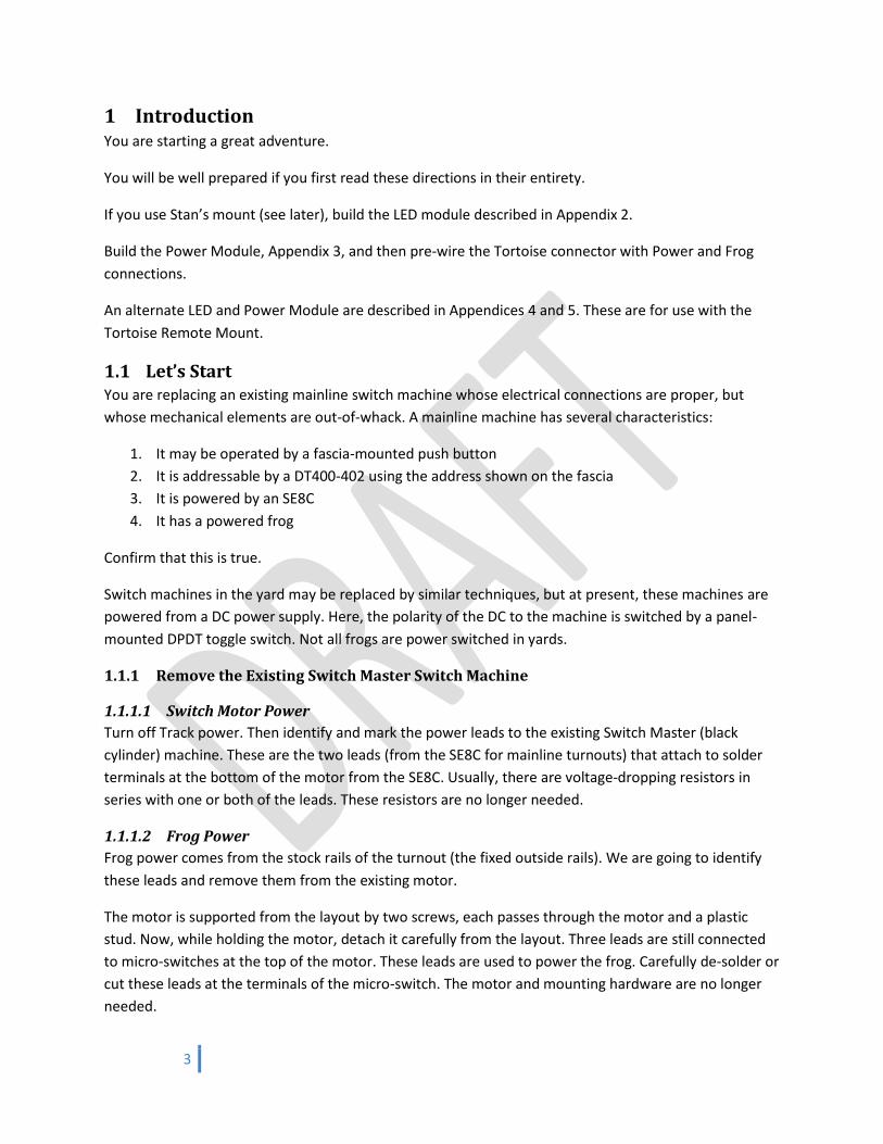
2. Bend the under-layout portion of the crank to the vertical.
It should be about ⅛-inch below the sub-roadbed.
3. Check for smooth action of the crank
4. I cut the under-layout portion of the crank to about 1.25
inches from the tubing.
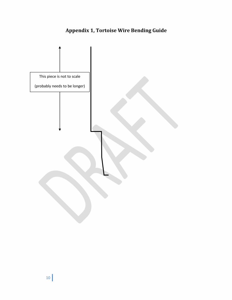
5. Build a shepherd’s crook (see photo and diagram) from
0.039-inch piano wire (K & S part #497). The top of the
crook should reach the top of the Tortoise when the
Tortoise is centered in its throw. The top of the crook is
about ½-inch forward of the lower part of the crook (see
second photo). See the bending guide in Appendix 1,
Tortoise Wire Bending Guide.
6. The hole above the bright screw needs to be opened with a #60 drill (0.040-inch). The fulcrum
hole is just fine.
7. Start with the Tortoise fulcrum near its maximum throw adjustment.
8. Apply heavy duty foam double-sided tape to the top of
the Tortoise (red piece in photo). If you clean the sub-
roadbed first (sticky tape works well), then you can
adjust the machine for best position. The tape allows
you to manually or electrically power the Tortoise to
test the throw.
9. Adjust the fulcrum as required.
10. Gently screw the Tortoise to the sub-roadbed, leaving
the tape in place.
11. Affix the fulcrum with some Blue Tack (gray stuff in the
photo) or other removable adhesive when finished.
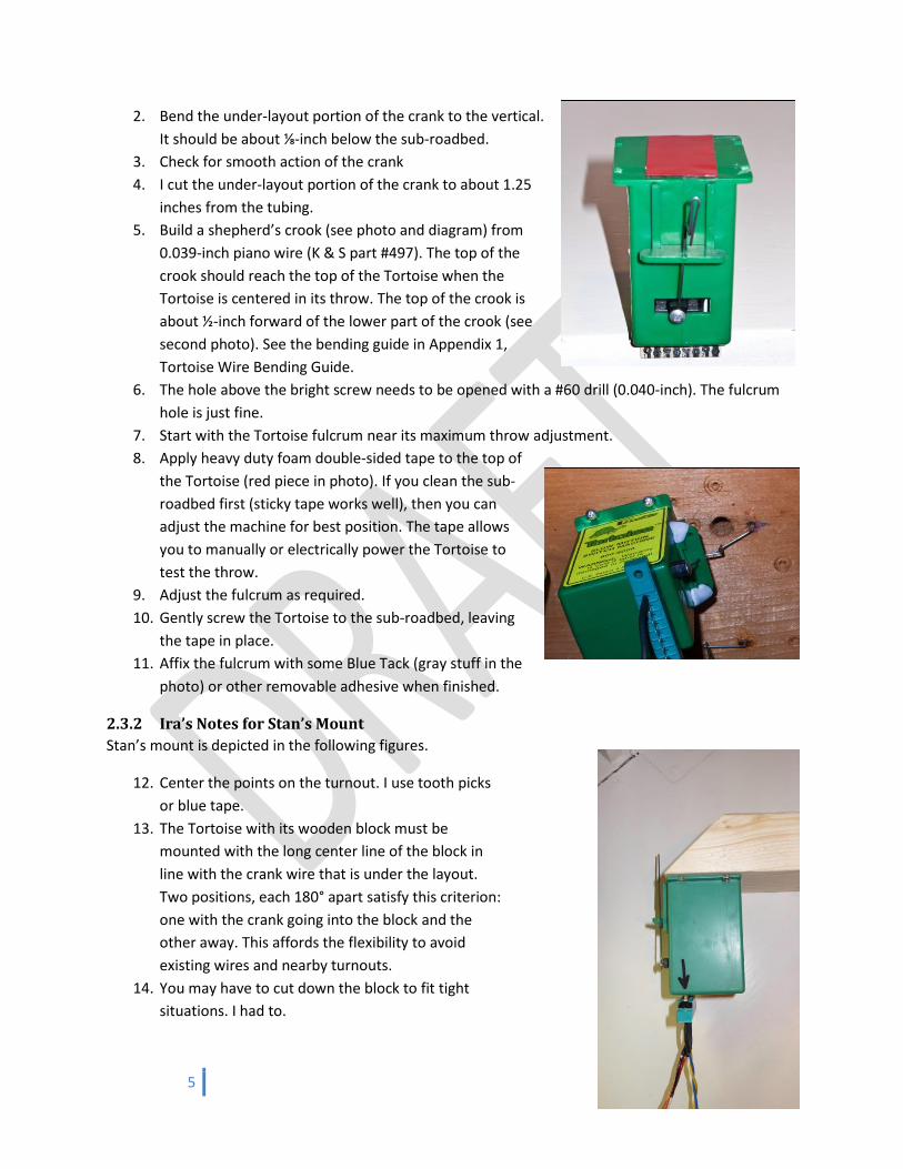
2.3.2 Ira’s Notes for Stan’s Mount
Stan’s mount is depicted in the following figures.
12. Center the points on the turnout. I use tooth picks
or blue tape.
13. The Tortoise with its wooden block must be
mounted with the long center line of the block in
line with the crank wire that is under the layout.
Two positions, each 180° apart satisfy this criterion:
one with the crank going into the block and the
other away. This affords the flexibility to avoid
existing wires and nearby turnouts.
14. You may have to cut down the block to fit tight
situations. I had to.

6
15. Use existing crank, but you may need to cut its length.
16. Use the three existing installations as guides for the position of the shepherd’s crook from the
crank pivot.
17. Start with the Tortoise fulcrum at its mid-point adjustment.
18. Affix the fulcrum with some Blue Tack or other removable adhesive when finished.
2.3.3 Ira’s Notes for the Remote Tortoise Mount:
1. Completely remove the existing crank and 1/16-inch brass tubing.
2. Use a long piece of brass tubing—one that extends about one-inch below the underside of the
top. This makes it easier to locate the remote head assembly.
3. Cut a new piece of tubing so it is slightly below the tie tops and extends approximately 1/8 inch
below the top. We want the crank to be as close to the tie tops as possible. FYI, I had to cut the
tubing to 1.0625” for the Baldwin area.
4. Use 0.032” piano wire, not the 0.025” provided in the kit.
3 Power the Tortoise
3.1 Important Note for Connecting to Tortoise No leads shall be soldered directly to the Tortoise. Rather, solder to the 8-pin female connectors
provided by the club.
All connections to the 8-pin Tortoise connector should be covered with heat shrink to protect the
mechanical integrity of the pins.
3.2 Wire Gauge All wiring shall be 22 gauge stranded wire. I believe that heavier wire needlessly strain the mounting
pins.
I use three feet of wire for each lead when I pre-build the wiring harnesses and LED and Power modules.
I then cut leads in place. You may want to inspect your site to ascertain a good starting length. Longer is
better because I would rather cut than de-solder and re-solder.
3.3 Mark One Side of the Tortoise and Connector The connector has no key. It can be connected in each of two ways. Therefore place the connector on
the machine and mark one side of each with a Sharpie so that reconnection is repeatable. If possible,
pick the side that will be visible after installation.
3.4 Pin Numbering Hold the Tortoise with the connector pointing down and the Tortoise mechanism arm facing you. Pins
are numbered 1-8, from left to right.
3.5 Wire Colors

7
Wiring is color coded as follows (if colored wire is not available use white wire and mark each end of
each wire with a Sharpie of proper color).
Pin Lead Color Function
1: Yellow Power from SE8C 2: Red Stock Rail “A” 3: Black Stock Rail “B” 4: Orange Frog 5: Orange (normally not used) Frog 6: Black (normally not used) Stock Rail “B” 7: Red (normally not used) Stock Rail “A” 8: Blue Power from SE8C
3.6 Bring Power from SE8C to Tortoise Connect Tortoise Pins 1 and 8 to power from the SE8C. Again, verify that all
voltage-dropping resistors have been removed.
The Tortoise may be tested by repeatedly pressing the push button. The
voltage across the Tortoise should be approximately 10 VDC.
3.7 Test the Pin 1 and 8 Polarity This is really important!
Now switch the turnout using a DT400. First send the “c” command. The
turnout should be set for the through path.
Next, send the thrown, “t”, command. The turnout should be set for the
diverging route.
If this not the case, then reverse SE8C leads to pins 1 and 8 at the European
connector of the Power Module.
3.8 LED Module
3.8.1 Insert the Pre-Built LED Module (Appendix 2) across the SE8C
The LED module is inserted (schematically) across the SE8C; it is physically connected to the Power
Module.
This module provides maximum voltage to the Tortoise.
The installer will note that one LED lights when the turnout is set for mainline and the other lights when
the turnout is set for diverging.
Now, the voltage across the Tortoise will be of the order of 10 VDC.
3.8.2 Insert the Pre-Built Alternate LED Module (Appendix 4) into either Power Lead
Pin 1 Pin 8
8
The LED module may be inserted into either the pin 1 or the pin 8 lead. This is at the installer’s
convenience. This module implicitly monitors the current through the Tortoise motor
The installer will note that one LED lights when the turnout is set for mainline and the other lights when
the turnout is set for diverging.
Now, the voltage across the Tortoise will be of the order of 6VDC, which may be insufficient for full
throw of the points (depending on overall lead length and SE8C performance).
3.9 Installation of LED into Fascia Insert the LED that lights for the diverging route into the fascia. Carefully tuck the other LED back from
the back side of the fascia so it may be seen from underneath the layout to confirm that power is
reaching the Tortoise from the SE8C.
3.10 Wire the Frog
3.10.1 Powered Frogs
All mainline frogs are powered at LAMRS. Frogs from heritage DC days might be quite long—say one
foot. Recently built turnouts may have very short frogs, only an inch. In all instances, the frogs are
powered.
Frog power comes from the stock rails of the turnout (the fixed outside rails). By wiring from these rails
we are assured that we are not causing problems with the PM42 gaps.
The frog must receive track power from either the “A” rail or the “B” rail depending upon how the
turnout is thrown. The stock rails provide the “A” and “B” rail sources. The frog is switched from one to
the other by a switch that is built right in the Tortoise machine. In fact, the Tortoise has two such
switches. Pins 2, 3, and 4 form one and pins 5, 6, and 7 the other.
3.10.2 Wiring Protocol
The frog and power are normally wired to terminals 2, 3, and 4.
At times, when one Tortoise and one Switch Master are used for a crossover, the installer will also use
Terminals 5, 6, and 7, to power the second frog, if necessary. In this situation the Tortoise powers both
frogs, leaving the Switch Master for motive power alone. Note that the Switch Master and the Tortoise
are powered from the same SE8C, but only the Switch Master will have resistors in its circuitry.
I have found that some Switch Masters have had their resistors removed. This will make difficult the
implementation of an LED that indicates the diverging route.
I recommend that any Switch Master have a 330-ohm, ½ watt resistor in series, with the combination
across the SE8C.
This is important!
The frog itself must be connected to either terminal 4 or to terminal 5! These are the output terminals.

9
The other two terminals (2 and 3 or 6 and 7) provide power from the stock rails of the turnout. These
are switched by the Tortoise.
3.11 Check the Frog Wiring
3.11.1 Ramp Meter Testing
1. Turn the Ramp Meter to ON. Test it on known working track.
2. Set the turnout to the closed, “c”, position. The turnout will be set for the main. Then use the
Ramp Meter to measure voltage between the frog and the fixed outer rail for that path. It
should indicate DCC voltage.
3. Do not switch the machine.
4. Next, measure voltage between the frog and the fixed rail for the through, “t”, position. There
should be no reading.
5. Set the turnout to the through, “t”, position. The turnout will be set for diverging. Then use the
Ramp Meter to measure voltage between the frog and the fixed outer rail for that path. It
should indicate DCC voltage.
6. Do not switch the machine.
7. Finally, measure voltage between the frog and the fixed rail for the closed, “c”, position. There
should be no reading.
3.12 Final Test Finally, run some locomotives and cars through the turnout. Use all possible paths.
10
Appendix 1, Tortoise Wire Bending Guide
This piece is not to scale
(probably needs to be longer)
11
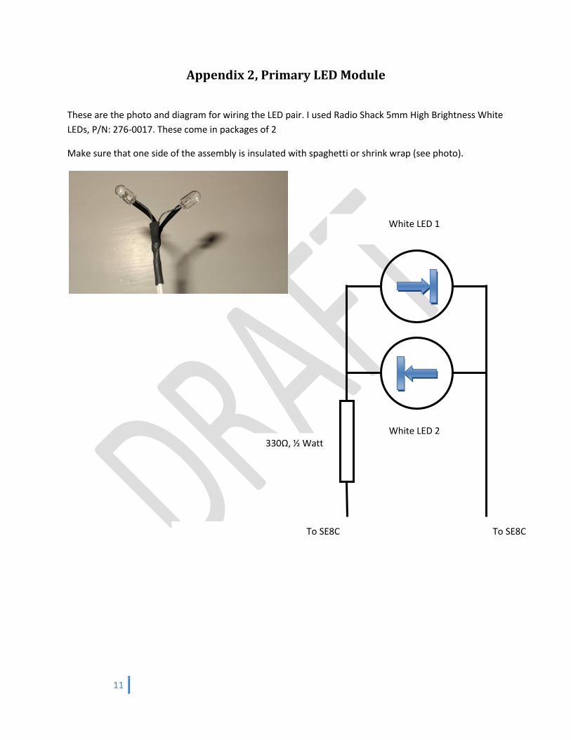
Appendix 2, Primary LED Module
These are the photo and diagram for wiring the LED pair. I used Radio Shack 5mm High Brightness White
LEDs, P/N: 276-0017. These come in packages of 2
Make sure that one side of the assembly is insulated with spaghetti or shrink wrap (see photo).
White LED 1
White LED 2
To SE8C To SE8C
330Ω, ½ Watt
12
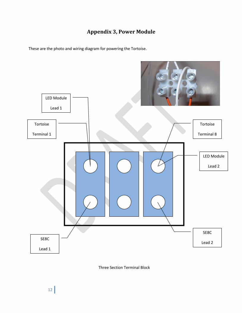
Appendix 3, Power Module
These are the photo and wiring diagram for powering the Tortoise.
Three Section Terminal Block
SE8C
Lead 2
Tortoise
Terminal 8
LED Module
Lead 1
Tortoise
Terminal 1
SE8C
Lead 1
LED Module
Lead 2
13
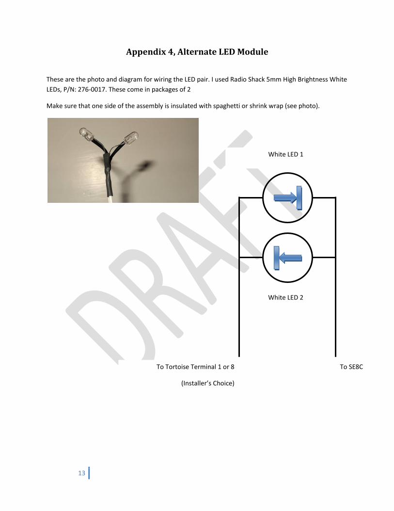
Appendix 4, Alternate LED Module
These are the photo and diagram for wiring the LED pair. I used Radio Shack 5mm High Brightness White
LEDs, P/N: 276-0017. These come in packages of 2
Make sure that one side of the assembly is insulated with spaghetti or shrink wrap (see photo).
White LED 1
White LED 2
To SE8C To Tortoise Terminal 1 or 8
(Installer’s Choice)
14
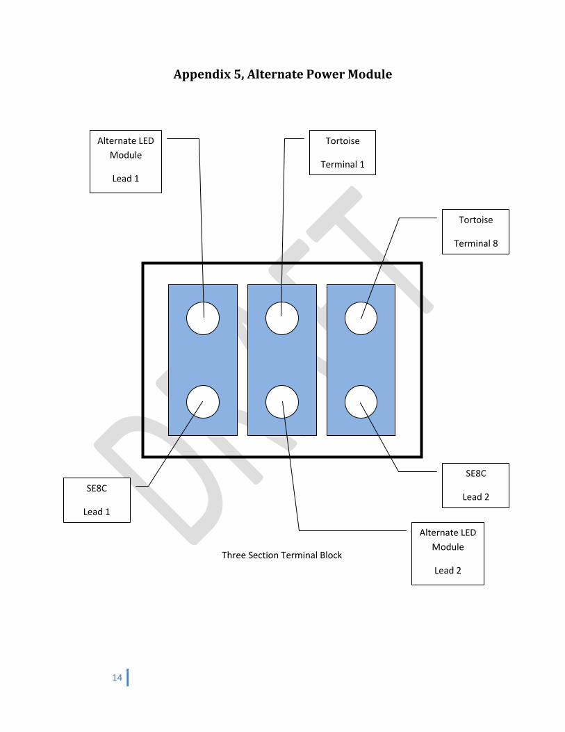
Appendix 5, Alternate Power Module
Three Section Terminal Block
SE8C
Lead 2
Tortoise
Terminal 8
Alternate LED
Module
Lead 1
Tortoise
Terminal 1
SE8C
Lead 1
Alternate LED
Module
Lead 2