wiring & configuration for fronius inverters - zendesk · fronius: fronius ig plus or cl (not...
TRANSCRIPT

DECK Monitoring LLC l 830 SW 10th Ave, Ste #200 • Portland, OR 97205 l www.deckmonitoring.com l 503.224.5546
Wiring & Configuration for Fronius Inverters
Fronius IG+ and CL Inverters can be attached to an Obvius AcquiSuite in order to communicate with DECK data servers. You will need a Fronius USB Converter, shown below:
The last Fronius COM card in your Fronius loop will connect to the Fronius USB Converter. This Converter then connects to the USB port on the Obvius 8810 or 8812 gateway. More detailed instructions follow.
Contents:
Supported Devices ............................................................................................ 2
Obvius Custom Module ................................................................................... 2
Parts List ............................................................................................................. 3
Wiring ................................................................................................................. 4
Configure Inverter ID ..................................................................................... 5
Configure Inverter Mode and Baud Rate ................................................. 6
Modbus Devices and USB Communications ............................................ 7
Diagnostics ....................................................................................................... 8
Note: Expected Error Conditions ................................................................. 9
v12_04_01
FRONIUS INVERTERS 2
Supported DevicesFronius: Fronius IG Plus or CL (not for use with Fronius IG)
Obvius: DAS that are compatible: AcquiSuite A8812-1and A8812-GSM, AcquiSuite EMB A8810, and AcquiLite EMB A7810. To determine if a particular product is supported, or for access to custom modules, contact Obvius Sales.
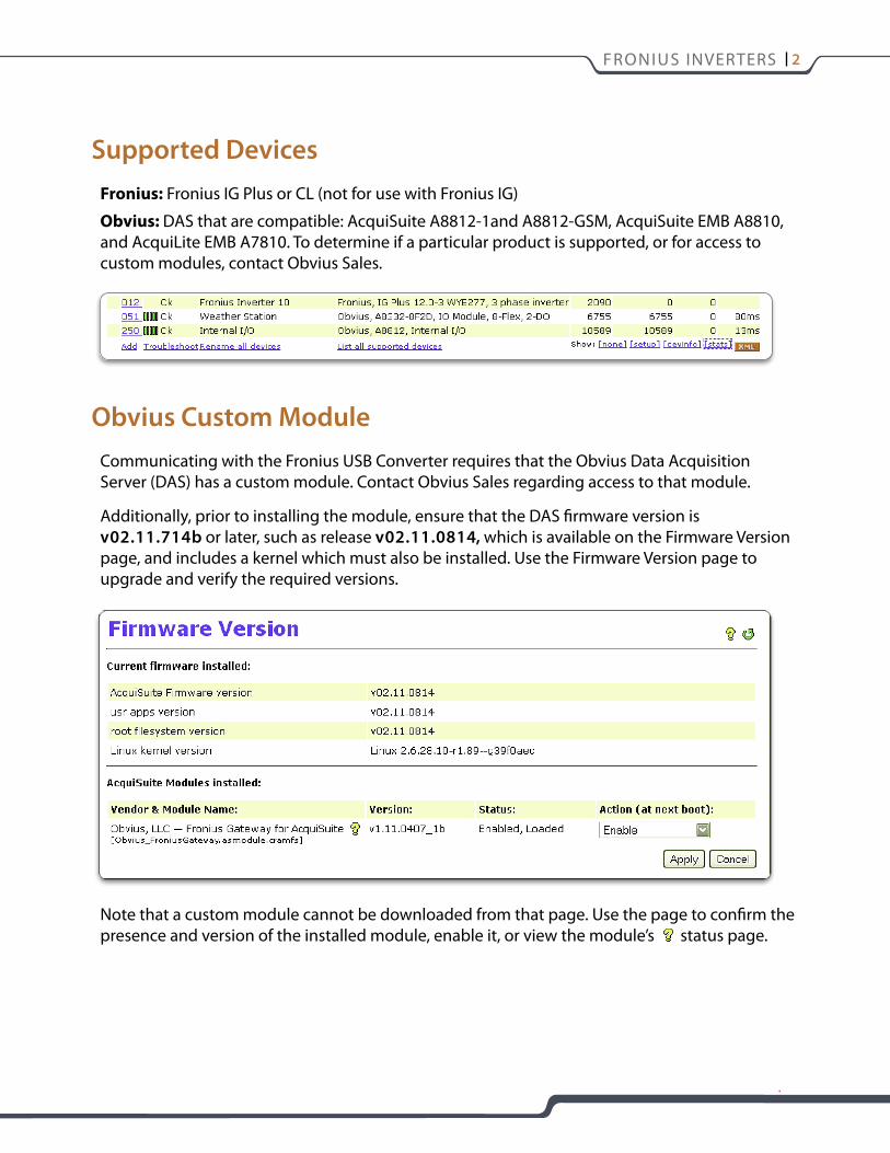
Obvius Custom ModuleCommunicating with the Fronius USB Converter requires that the Obvius Data Acquisition Server (DAS) has a custom module. Contact Obvius Sales regarding access to that module.
Additionally, prior to installing the module, ensure that the DAS firmware version isv02.11.714b or later, such as release v02.11.0814, which is available on the Firmware Versionpage, and includes a kernel which must also be installed. Use the Firmware Version page toupgrade and verify the required versions.
Note that a custom module cannot be downloaded from that page. Use the page to confirm the presence and version of the installed module, enable it, or view the module’s status page.
FRONIUS INVERTERS 3
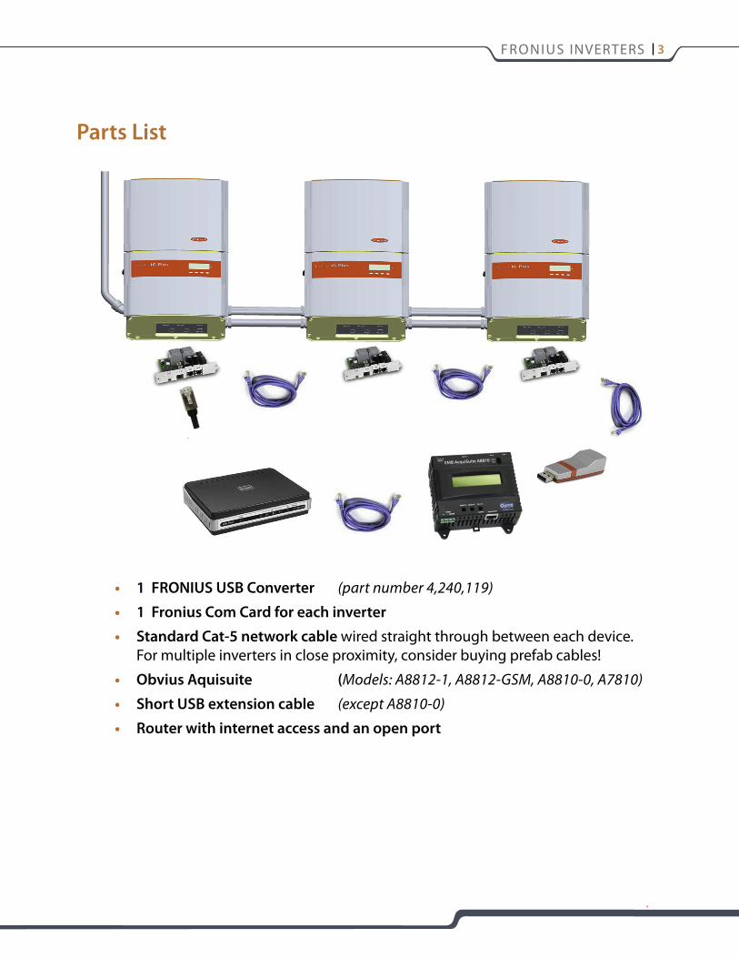
Parts List
• 1 FRONIUS USB Converter (part number 4,240,119)
• 1 Fronius Com Card for each inverter
• Standard Cat-5 network cable wired straight through between each device. For multiple inverters in close proximity, consider buying prefab cables!
• Obvius Aquisuite (Models: A8812-1, A8812-GSM, A8810-0, A7810)
• Short USB extension cable (except A8810-0)
• Router with internet access and an open port

FRONIUS INVERTERS 4
WiringDuring planning stage, spec ½ conduit between inverters for cable if desired, NEMA rated enclosure for AquiSuite to suit location, AC power for Aquisuite and router.
Install Com Card in each inverter.
Install terminal plug into “in” port on Com Card farthest from AcquiSuite.
Daisy-chain remaining inverters with Cat-5 cable and RJ 45 plugs wired straight through from “out” to “in” on Com Cards. Be sure to test!
We highly recommend using prefabricates 3’ cables between inverters.
Plug cable into Fronius USB Converter. Cable can be up to 3,200 feet.
Plug Fronius Converter into USB port on AquiSuite EMB.
For AquiSuite A8812-1, open case and use a short USB extension cable to plug in converter, as it will extend past case.
Secure wiring.
1
2
3
4
7
5
8
6
9
FRONIUS INVERTERS 5
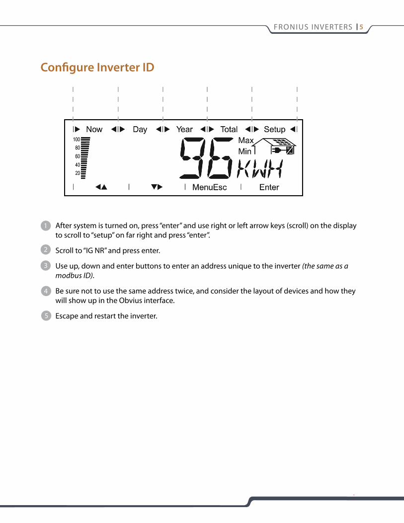
Configure Inverter ID
After system is turned on, press “enter” and use right or left arrow keys (scroll) on the display to scroll to “setup” on far right and press “enter”.
Scroll to “IG NR” and press enter.
Use up, down and enter buttons to enter an address unique to the inverter (the same as a modbus ID).
Be sure not to use the same address twice, and consider the layout of devices and how they will show up in the Obvius interface.
Escape and restart the inverter.
1
2
3
4
5
FRONIUS INVERTERS 6
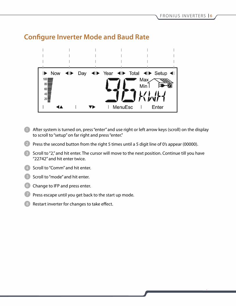
Configure Inverter Mode and Baud Rate
After system is turned on, press “enter” and use right or left arrow keys (scroll) on the display to scroll to “setup” on far right and press “enter.”
Press the second button from the right 5 times until a 5 digit line of 0’s appear (00000).
Scroll to “2,” and hit enter. The cursor will move to the next position. Continue till you have “22742” and hit enter twice.
Scroll to “Comm” and hit enter.
Scroll to “mode” and hit enter.
Change to IFP and press enter.
Press escape until you get back to the start up mode.
Restart inverter for changes to take effect.
1
2
3
4
5
6
7
8
FRONIUS INVERTERS 7
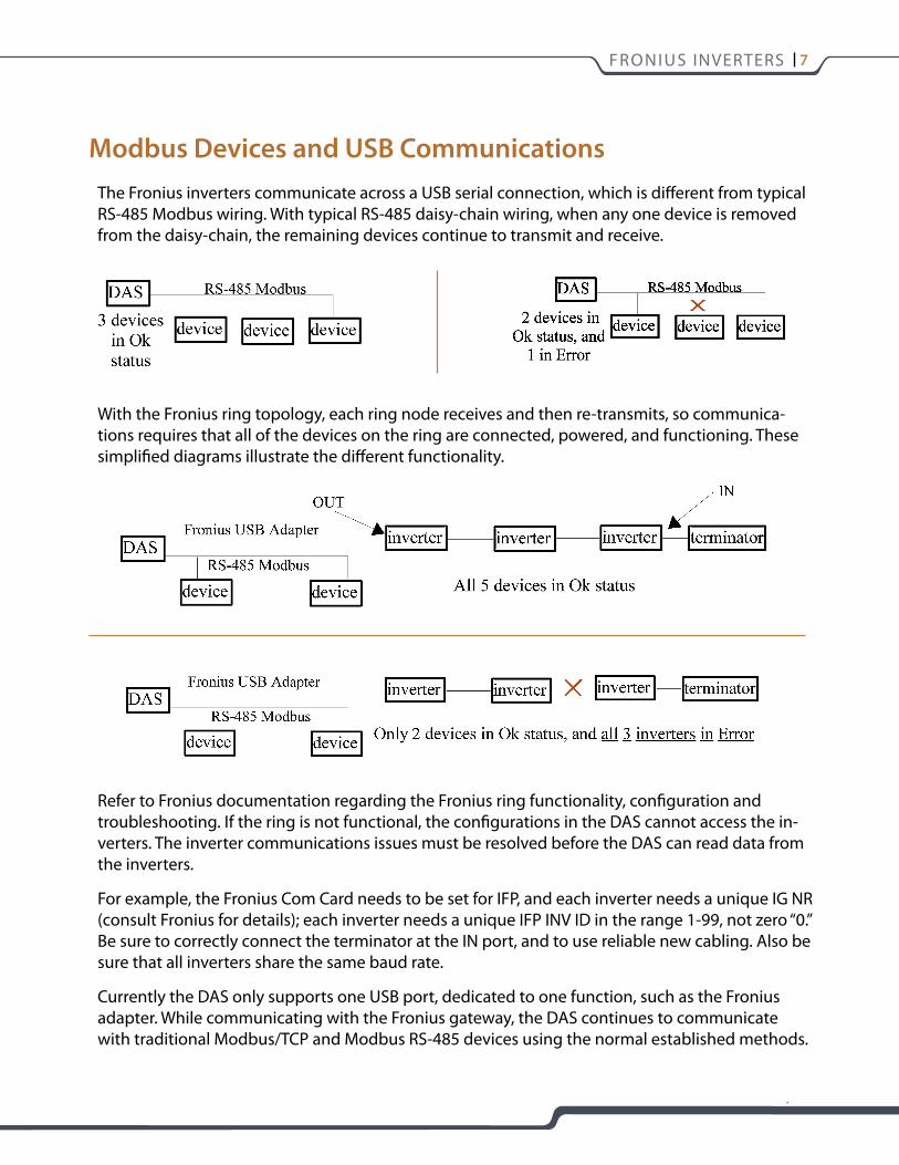
Modbus Devices and USB CommunicationsThe Fronius inverters communicate across a USB serial connection, which is different from typical RS-485 Modbus wiring. With typical RS-485 daisy-chain wiring, when any one device is removed from the daisy-chain, the remaining devices continue to transmit and receive.
With the Fronius ring topology, each ring node receives and then re-transmits, so communica-tions requires that all of the devices on the ring are connected, powered, and functioning. These simplified diagrams illustrate the different functionality.
Refer to Fronius documentation regarding the Fronius ring functionality, configuration and troubleshooting. If the ring is not functional, the configurations in the DAS cannot access the in-verters. The inverter communications issues must be resolved before the DAS can read data from the inverters.
For example, the Fronius Com Card needs to be set for IFP, and each inverter needs a unique IG NR (consult Fronius for details); each inverter needs a unique IFP INV ID in the range 1-99, not zero “0.” Be sure to correctly connect the terminator at the IN port, and to use reliable new cabling. Also be sure that all inverters share the same baud rate.
Currently the DAS only supports one USB port, dedicated to one function, such as the Fronius adapter. While communicating with the Fronius gateway, the DAS continues to communicate with traditional Modbus/TCP and Modbus RS-485 devices using the normal established methods.
FRONIUS INVERTERS 8
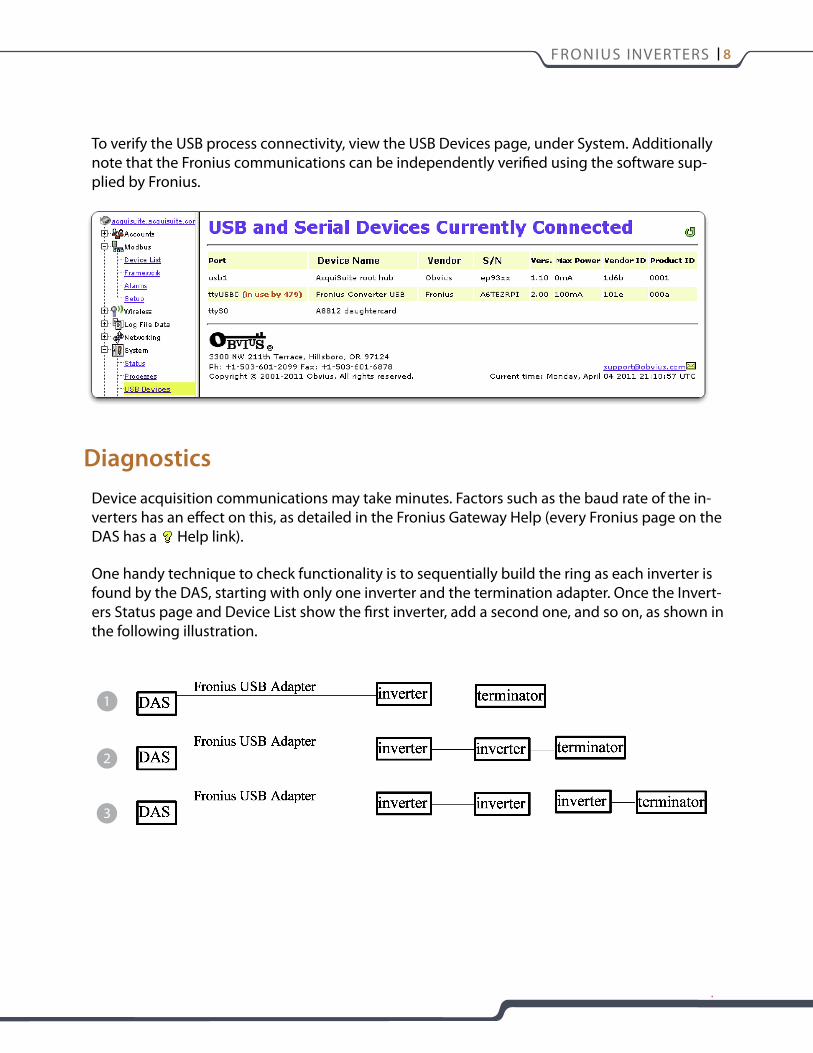
To verify the USB process connectivity, view the USB Devices page, under System. Additionally note that the Fronius communications can be independently verified using the software sup-plied by Fronius.
DiagnosticsDevice acquisition communications may take minutes. Factors such as the baud rate of the in-verters has an effect on this, as detailed in the Fronius Gateway Help (every Fronius page on the DAS has a Help link).
One handy technique to check functionality is to sequentially build the ring as each inverter is found by the DAS, starting with only one inverter and the termination adapter. Once the Invert-ers Status page and Device List show the first inverter, add a second one, and so on, as shown in the following illustration.
1
2
3
FRONIUS INVERTERS 9
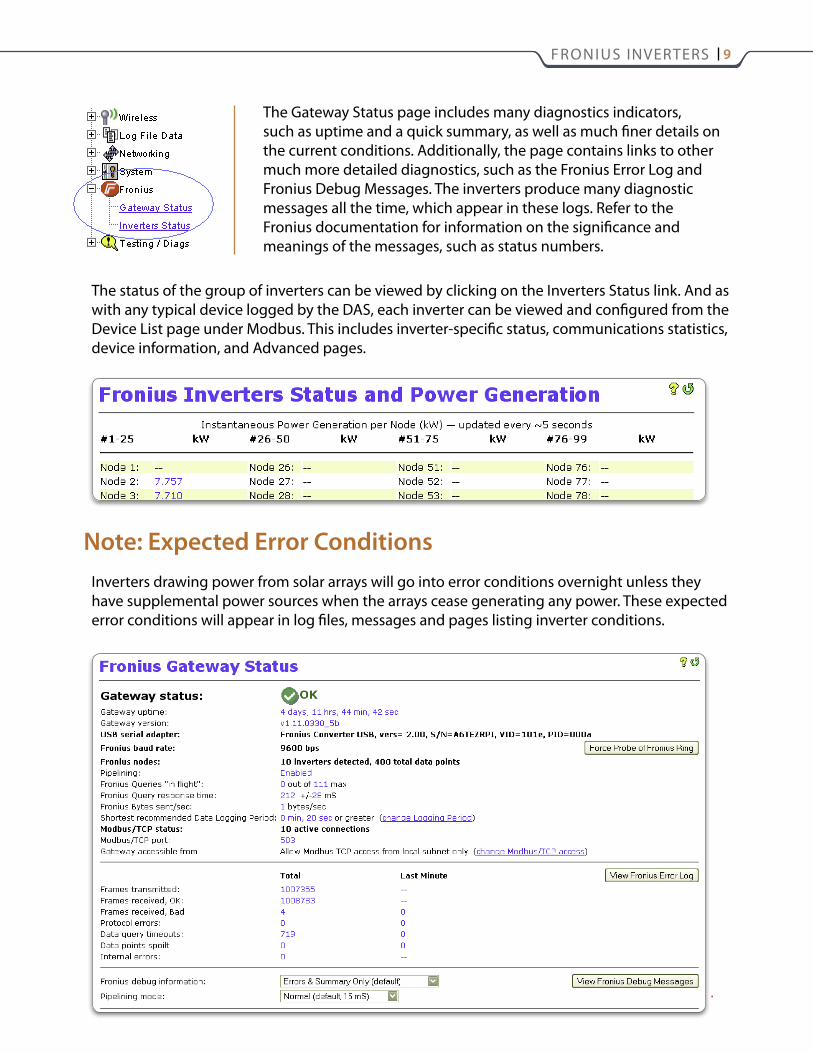
The Gateway Status page includes many diagnostics indicators,such as uptime and a quick summary, as well as much finer details onthe current conditions. Additionally, the page contains links to othermuch more detailed diagnostics, such as the Fronius Error Log andFronius Debug Messages. The inverters produce many diagnosticmessages all the time, which appear in these logs. Refer to theFronius documentation for information on the significance andmeanings of the messages, such as status numbers.
The status of the group of inverters can be viewed by clicking on the Inverters Status link. And as with any typical device logged by the DAS, each inverter can be viewed and configured from the Device List page under Modbus. This includes inverter-specific status, communications statistics, device information, and Advanced pages.
Note: Expected Error ConditionsInverters drawing power from solar arrays will go into error conditions overnight unless they have supplemental power sources when the arrays cease generating any power. These expected error conditions will appear in log files, messages and pages listing inverter conditions.