wiring diagrams - dms.hvacpartners.comdms.hvacpartners.com/docs/1005/public/06/38aqs-2w.pdf ·...
TRANSCRIPT
Manufacturer reserves the right to discontinue, or change at any time, specifications or designs without notice and without incurring obligations.PC 111 Catalog No. 533-80074 Printed in U.S.A. Form 38AQS-2W Pg 1 11-02 Replaces: 38AQS-1WBook 1 4
Tab 5a 5a
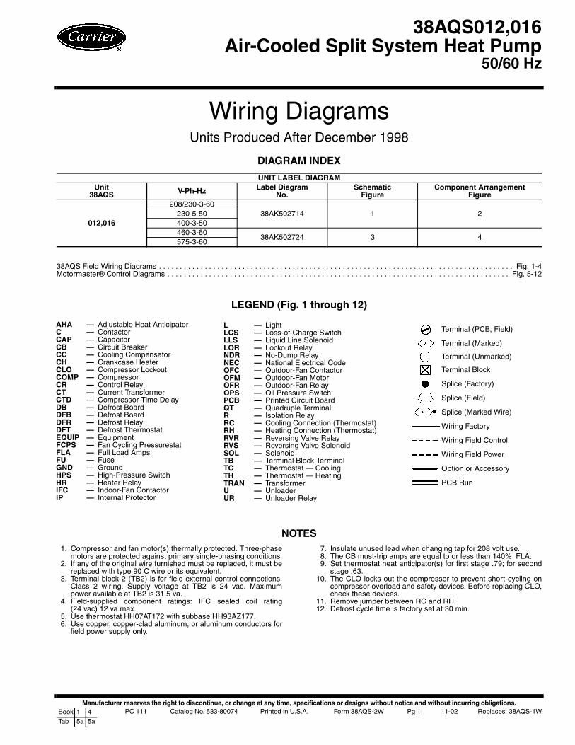
Wiring DiagramsUnits Produced After December 1998
DIAGRAM INDEX
38AQS Field Wiring Diagrams . . . . . . . . . . . . . . . . . . . . . . . . . . . . . . . . . . . . . . . . . . . . . . . . . . . . . . . . . . . . . . . . . . . . . . . . . . . . . . . . . . . . . Fig. 1-4Motormaster® Control Diagrams . . . . . . . . . . . . . . . . . . . . . . . . . . . . . . . . . . . . . . . . . . . . . . . . . . . . . . . . . . . . . . . . . . . . . . . . . . . . . . . . . . Fig. 5-12
LEGEND (Fig. 1 through 12)
NOTES1. Compressor and fan motor(s) thermally protected. Three-phase
motors are protected against primary single-phasing conditions.2. If any of the original wire furnished must be replaced, it must be
replaced with type 90 C wire or its equivalent.3. Terminal block 2 (TB2) is for field external control connections,
Class 2 wiring. Supply voltage at TB2 is 24 vac. Maximumpower available at TB2 is 31.5 va.
4. Field-supplied component ratings: IFC sealed coil rating(24 vac) 12 va max.
5. Use thermostat HH07AT172 with subbase HH93AZ177.6. Use copper, copper-clad aluminum, or aluminum conductors for
field power supply only.
7. Insulate unused lead when changing tap for 208 volt use.8. The CB must-trip amps are equal to or less than 140% FLA.9. Set thermostat heat anticipator(s) for first stage .79; for second
stage .63.10. The CLO locks out the compressor to prevent short cycling on
compressor overload and safety devices. Before replacing CLO,check these devices.
11. Remove jumper between RC and RH.12. Defrost cycle time is factory set at 30 min.
UNIT LABEL DIAGRAMUnit
38AQS V-Ph-Hz Label DiagramNo.
SchematicFigure
Component ArrangementFigure
012,016
208/230-3-6038AK502714 1 2230-5-50
400-3-50460-3-60
38AK502724 3 4575-3-60
38AQS012,016Air-Cooled Split System Heat Pump
50/60 Hz
AHA — Adjustable Heat AnticipatorC — Contactor CAP — CapacitorCB — Circuit BreakerCC — Cooling CompensatorCH — Crankcase HeaterCLO — Compressor LockoutCOMP — CompressorCR — Control RelayCT — Current TransformerCTD — Compressor Time DelayDB — Defrost BoardDFB — Defrost BoardDFR — Defrost RelayDFT — Defrost ThermostatEQUIP — EquipmentFCPS — Fan Cycling PressurestatFLA — Full Load AmpsFU — FuseGND — GroundHPS — High-Pressure SwitchHR — Heater RelayIFC — Indoor-Fan ContactorIP — Internal Protector
L — LightLCS — Loss-of-Charge SwitchLLS — Liquid Line SolenoidLOR — Lockout RelayNDR — No-Dump RelayNEC — National Electrical CodeOFC — Outdoor-Fan ContactorOFM — Outdoor-Fan MotorOFR — Outdoor-Fan RelayOPS — Oil Pressure SwitchPCB — Printed Circuit BoardQT — Quadruple TerminalR — Isolation RelayRC — Cooling Connection (Thermostat)RH — Heating Connection (Thermostat)RVR — Reversing Valve RelayRVS — Reversing Valve SolenoidSOL — SolenoidTB — Terminal Block TerminalTC — Thermostat — CoolingTH — Thermostat — HeatingTRAN — TransformerU — UnloaderUR — Unloader Relay
Terminal (PCB, Field)
Terminal (Marked)
Terminal (Unmarked)
Terminal Block
Splice (Factory)
Splice (Field)
Splice (Marked Wire)
Wiring Factory
Wiring Field Control
Wiring Field Power
Option or Accessory
PCB Run
2
SEQUENCE OF OPERATION — 38AQS012,016 OUTDOOR UNIT
Assume the power is on and the thermostat is set at SYS-TEM AUTO, FAN AUTO. and desired temperature.
Cooling — If power to unit has been off for an extendedperiod of time, energize crankcase heater at least 24 hours priorto starting compressor.
The indoor fans, outdoor fans, and compressor start within5 minutes (due to compressor time delay) on command fromthe controlling thermostat in either the Cooling or the Heatingmode of operation. When first stage cooling is required, ther-mostat (TC1) closes, causing the heat pump to start with anunloaded compressor. When TC2 closes, demanding additionalcooling, the compressor loads. In a system with a one-stagethermostat, the unit may be wired so the compressor starts fullyloaded. The RVS (reversing valve solenoid) is deenergizedduring Cooling mode operation.
HeatingFIRST STAGE — When the thermostat (TH1) calls for heat-ing, the indoor-fan motor, outdoor-fan motors, and the com-pressor (fully loaded) are energized. The RVS is energized inthe Heating mode.
SECOND STAGE — If additional heating is required, TH2on the thermostat closes, causing the auxiliary heat supply (i.e.,electric resistance heat) to be energized in 1 or 2 stages depend-ing on the number of stages available and whether the outdoorthermostats are closed.
Defrost Cycle — Defrost is initiated by a timer whichmay be set to 30, 50, or 90 minutes. The cycle begins when thedefrost timer motor contacts close for 20 seconds. If the defrostthermostat is closed, the reversing valve and outdoor-air fansare deenergized. The unit operates on this modified Coolingmode to defrost the coil. The defrost cycle continues until thedefrost thermostat or defrost high pressure switch opens or10 minutes have elapsed.
When the unit is in the defrost cycle, electric resistance heatis energized to prevent cold air recirculation during this modi-fied Cooling mode.
Air Circulation — When the fan switch is at FAN ON,the indoor-air fans operate continuously to provide ventilation.The thermostat operates the other components as describedabove.

3
Fig. 1 — Schematic — 38AQS012,016; 208-230/3/60, 230/3/50 and 400/3/50 Units

4
Fig. 2 — Component Arrangement — 38AQS012,016; 208-230/3/60, 230/3/50 and 400/3/50 Units

5
Fig. 3 — Schematic — 38AQS012,016; 460/3/60 and 575/3/60 Units

6
Fig. 4 — Component Arrangement — 38AQS012,016; 460/3/60 and 575/3/60 Units

7
MOTORMASTER® CONTROL(LOW AMBIENT KIT)
INSTALLATION
The accessory low-ambient kit contains a fan speed (Motor-master) control device activated by a temperature sensor(Fig. 5). The kit controls condenser fan motor speed inresponse to the saturated condensing temperature. For outdoortemperatures down to –20 F (–29 C), it maintains the condens-ing temperature at 100 ± 10 F (38 ± 6 C).
The low-ambient (Motormaster) control consists of a solid-state circuit on a printed circuit board encased in an aluminumextrusion. The control must be fastened to a panel in the unit,and the sensor assembly (Fig. 5) mounted to a return bend onthe unit’s condenser coil. Parts necessary for mounting controland sensor are included in the kit.
Pre-InstallationDISCONNECT UNIT POWER — To prevent electric shock,open and tag all disconnects before modifying the condensingunit.FABRICATE AND INSTALL WIND BAFFLES — The38AQS units equipped with the low-ambient kit require baf-fles to prevent wind crosscurrents from causing abnormaloperation as the fan is modulated. Construct and installwind baffles. See Fig. 6.
VERIFY POWER WIRING — Power wiring must complywith NEC (National Electrical Code) and all requirements.Confirm that supply voltage meets minimum voltage specifiedon the unit’s rating plate and that it matches the voltage ratingof the low-ambient kit.
LOW-AMBIENTCONTROL
SENSORASSEMBLY
AB
C
Fig. 5 — Low-Ambient (Motormaster) Control andSensor Assembly
KIT NO. VOLTS AMPS A B C32LT900301 All except 460 8.0 57/8 63/16 33/832LT900611 460 4.0 57/8 73/8 33/8

8
DIMENSIONS (ft-in.)
*As viewed from access panel side.
Fig. 6 — Wind Baffle Details
BAFFLE LOCATION ARight-Hand Side* 2-511/16 (754.3 mm)Back 5-81/8 (1730.3 mm)Left-Hand Side* 3-07/16 (925.6 mm)

9
Installation — After completing the pre-installation steps,proceed as follows:MOUNT CONTROL ASSEMBLY
1. See Fig. 7 for the location of the access panel andMotormaster® low-ambient control in the bottom of theunit. Remove the access panel.
2. Using the template supplied in this document, drill pilotholes for mounting the low-ambient control.
3. Fasten control to unit with four no. 10 sheet metal screwsand star lockwashers provided. Lockwashers are requiredto ensure electrical ground with condensing unit.
MOUNT SENSOR ASSEMBLY
1. See Fig. 8 to determine where to locate sensor on coilreturn bend. As shown in Fig. 9, fasten sensor to returnbend with the supplied screw, plate washers, and nut. SeeTable 1 for sensor temperature vs resistance values.
Table 1 — Sensor (Thermistor) Temperaturevs Resistance
2. Coil and secure excess wire inside the unit near the sensoror next to the low ambient control; provide additionalprotection against abrasion or movement of the wire ifnecessary.
3. Reinstall the access panel.
When drilling holes, be careful not to damage return coilbends inside unit.
The sensor assembly is fragile. Handle with care.
TEMPERATURE NOMINAL RESISTANCE(Ohms)F C
60 16 775070 21 590077 25 500080 27 465090 32 3650
100 38 2875110 43 2275120 49 1850
Fig. 7 — Motormaster Control Location
Fig. 8 — Motormaster® Sensor Location — 38AQS012,016

Manufacturer reserves the right to discontinue, or change at any time, specifications or designs without notice and without incurring obligations.PC 111 Catalog No. 533-80074 Printed in U.S.A. Form 38AQS-2W Pg 10 11-02 Replaces: 38AQS-1WBook 1 4
Tab 5a 5a
Copyright 2002 Carrier Corporation
INSTALL CONTROL POWER WIRING — Wire the Motor-master® low-ambient control to the unit’s power circuit asshown in Fig. 10 and 11; refer to the following sections forvarious unit voltages.
Install the isolation relay coil in parallel with the reversingvalve relay coil. This takes the Motormaster control out of thecondenser fan motor circuit when the 38AQS switches to theheating cycle. (See Fig. 12.)
Power wiring must comply with all local and nationalrequirements. All units except 460-v, 3-ph, 60-Hz use Motor-master control, Carrier Part No. 32LT900301. The 460-v unitsuse Motormaster control, Carrier Part No. 32LT900611.ALL UNITS EXCEPT 575-3-60 — For these units, withoutspecial transformer, wire Motormaster control to condenser fanmotor circuit as shown in Fig. 10.575-3-60 UNITS — The 575-v units require a special field-installed transformer and fan motor. Wire special transformer(part no. HT01AH859) and Motormaster control to special fanmotor (part no. HC44VL852) as shown in Fig. 11.
Blue wire from CB1-13 to CAP1 must be reconnected fromCB1-13 to TRAN2-H2.
Blue wire from CAP1 to TRAN2-H2 must be reconnectedfrom CAP1 to field-installed transformer.VERIFY OPERATION — Turn on the unit power and set thethermostat below the ambient room temperature. If the unitis equipped with a Time Guard® II circuit, wait at least5 minutes.
After the compressor starts, the fan speed is modulatedaccording to the condensing temperature and then maintaineduntil the set point is achieved.
If fan motor no. 1 does not start, verify the following condi-tions and correct as necessary:• Condensing unit power is on.• Power is present at fan motor relay contacts (or trans-
former output when one is installed).• Sensor wire connections inside the low-ambient control
are tight.If the preceding conditions are met and fan motor no. 1 still
does not start, perform corrective procedures or replace com-ponents as follows:• Jumper the power wires (BLK-to-BLK) in the Motor-
master control. If the motor does not run, check motorwiring and run capacitor. Replace capacitor and motor ifnecessary. If the motor runs, ensure the fan motor iswired in series with the control. Refer to Fig. 10.
• If the fan motor runs when connected to the single-phasevoltage supply but does not run when connected inseries with the Motormaster control, AND the returnbend where the sensor is mounted is warm, short thesensor leads (BLU-to-RED). If the motor runs, replacethe sensor. If the motor does not run, replace the controland sensor assembly.
IMPORTANT: Wire low-ambient control in series withfan motor.
Fig. 9 — Sensor Installation
*Use control part no. 32LT900301 for all unit voltages except 460 v.Use control part no. 32LT900611 for 460-v units.
Fig. 10 — Motormaster Control Power Wiringfor All Units except 575-V
Fig. 11 — Motormaster Control Power Wiringfor 575-V Units Using 208/230-V Motors
W1 W2 ORN
ORN
ORN HR
RVR2
TRAN2CR3
RVR2
RVR3
HRTB2C
WHT
RVR1WHT
3
3
3
33
3
3
CWHTWHT
WHT
WHTWHT
1
1
1
RVR3
R
ORN ORN
RVR1
ORN
ORN
Fig. 12 — Motormaster Control Circuit Wiring with Isolation Relay
NOTE: Isolation Relay (R) (field supplied) HN61KQ120 orequivalent.

11
MOTORMASTER® CONTROL TEMPLATE

Manufacturer reserves the right to discontinue, or change at any time, specifications or designs without notice and without incurring obligations.PC 111 Catalog No. 533-80074 Printed in U.S.A. Form 38AQS-2W Pg 12 11-02 Replaces: 38AQS-1WBook 1 4
Tab 5a 5a
Copyright 2002 Carrier Corporation
- -
- -
- -
- -
- -
- -
- -
- -
- -
- -
- -
- -
- -
- -
- -
- -
- -
- -
- -
- -
- -
- -
- -
- -
- -
- -
- -
- -
- -
- -
- -
- -
- -
- -
- -
- -
- -
- -
- -
- -
- -
- -
- -
- -
- -
- -
- -
- -
- -
- -
- -
- -
- -
- -
- -
- -
- -
- -
- -
- -
- -
- -
- -
- -
- -
- -
- -
- -
- -
- -
- -
- -
- -
- -
- -
- -
- -
- -
- -
- -
- -
- -
- -
- -
- -
- -
-- -
- -
- -
- -
- -
- -
- -
- -
- -
- -
C
UT
ALO
NG
DO
TT
ED
LIN
EC
UT
ALO
NG
DO
TT
ED
LIN
E