wirlessnetwork - near east...
TRANSCRIPT
NEAR EAST UNIVERSITY
Faculty of Engineering
Department of Computer Engineering
WIRLESS NETWORK
Graduation ProjectCOM-400
Student: Belal Abu Salim (20001182)
Supervisor: Prof. Dr Fakhraddin Mamedov
••• •..
Nicosia - 2003
ııı•ı~ıJll~IJJllll 111NEU
•
. .>
~ ~\
First, I would like to deeply thank my supervisor Prof Dr Fakhraddin Mamedov for~ _c;;.--
his invaluable advice and belief in my work and myself over the course of this Graduation Project.
ACKNOWLEDGMENT
Second, I would like to express my gratitude to Near East University for the scholarship that made the work possible.
Third, I thank my family for their constant encouragement and support during the preparation of this project.
Last but not least I would also like to thank all of my friends who were always available for my assistance throughout this project. "
•
••

Abstract
When the wireless communications is coming to the offices and the homes, there
are some new wireless LANs issues to be taken care of Today we have continuously
growing markets for the wireless LANs, There is also some discussion about the threats
and vulnerabilities in wireless networks compared to wired networks. And last but not
least the protocols and mechanisms needed in the wireless LAN are described.
This thesis will be presented in 6 sections; each or which will contain many subsections
dealing with various relevant issues which need to be considered when designing a
WAP application.Chapter 1- we will define wireless networks and its connections.
Chapter 2- This paper addresses the Wireless Local Area Network (WLAN). The
wireless system for Local Area Network (LAN) is an important landmark in the history
of the Internet and electronic applications. It opens up existing systems, databases and
intranets to mobile equipment such as telephones and hand-held terminals through a
graphical customer interface. The most important benefit of WLAN is that it is
independent of different mobile technologies that are used in different parts of the
world.CHAPTER 3- will provide a general introduction both to WAP and the application,
which has been designed. This will include definitions, the benefits of WAP, and a
literary review (wap forum, wapnet .com, phone.com)CHAPTER 4- will discuss the practicalities and the actual architecture of the wireless
application protocol. oCHAPTER 5 - will address the physical implementation of the author's application.
""
This will include a subsection on W.M.L (wireless mark-up language) as well as the•
presentation of the actual cards of programming language. .....• CHAPTER 6- will seek to evaluate the possibilities for WAP and, how successful the
author's application has been. It will also provide an in-depth analysis into the author's
study.
11

TABLE OF CONTENTS
ACKNOWLEDGMENTABSTRACTTABLE OF CONTENTSINTRODUCTIONCHAPTER ONE: INTRODUCTION
1.1 What Is Wireless Networking?1.2 What Is a Wireless Network Made Up Of?1.3 IEEE802.111.4 Mix Wireless Equipment from Different Vendo1.5 Connect a Wireless LAN with Computers on a Wired LAN1.6 The Range of a Wireless Network1. 7 Wireless Networked Computers Using a Single Access Point1.8 Use More than One Access Point1.9 Roaming1.10 Use a Wireless Network to Interconnect Two LANs1.11 It Is True That Wireless Networking1.12 Wireless Networking and the Internet
1.12.1 Use a Wireless Network to Share an Internet Connection1.12.2 Share a Single Internet Connection Point1.12.3 IfI Use A Wireless Network1.12.4 Can Networking Software Identify A Wireless Computer
1.13 The Future of Wireless NetworksCHAPTER TWO: WIRELESS LAN NETWORKING
..
2.1 Mobility2.2 Range2.3 Frequency2.4 Equipment Cost2.5 Equipment Bandwidth and Performance2.6 Equipment Procurement and Installation2.7 Security2.8 Wireless LAN Applications •
2.8.1 Health Care2.8.2 Education and Research
2.9 Analysis2.9.1 Advantages2.9.2 Disadvantages
2.1O Future of WLANCHAPTER THREE: WİRELESS APPLİCATİON PROTOCOL
•..
3.1 What Is WAP?3.2 A Wireless Application- Student Service3.3 Literary Review3.4 The Goals OfWAP Forum
iii
ii111
13335 56677991011111213141416
161720
.2224262830313133333335 36
36363839

3.5 Benefits OfWAP 39
CHAPTER FOUR: THE ARCHİTECTURE AND WORKİNGSOFWAP. 414.1 Background 414.2 Network Operators 424.3 Components OfW AP Architecture And It's Basic Workings 42
4.3 .1 How A WAP Application Runs Between Client And Server. 434.3.2 So How Do These Components Work Together? 44
4.4 WAP System Architecture 444.4.1 WIRELESS APPLICATION ENVIRONMENT (WAE) 464.4.2 Wireless Session Layer (WSP) 464.4.3 Wireless Transaction Layer (WTP) 474.4.4 Security Layer (WTLS) 47
4.4.5 Transport Layer (WDP) 47
4.4.6 Network Layer 47
4.5 Additional Features Of WAP Architecture 48
4.6 How WAP Content Is Displayed. 48
4.7 Wireless Mark-Up Language (WML) And WML Script. 49
CHAPTER FIVE: DEVELOPING A WAP APPLICATION 50
5.1 Up Link Platform 505.1.1 How the Up Link Platform Works 51
5.2 Using the Up Simulator 515.3 Functions on the Simulator 525.4 The Design of the Authors Application 535.5 Developing A WAP Application 545.6 Creating a Static Title WML File 555.7 A Card By Card Analysis of the Author Application • 56
CHAPTER SIX :TESTİNG AND EVALUATİON 61
..61
62
62
64
..6.1 Evaluation
-6. 1 .1 Possible Enhancements
6.1.2 Success Of The Application
CONCLUSION
•
REFERENCESAPPENDIX AAPPENDIXB
67
70
71
iv

INTRODUCTION
Increased use of laptop computers within the enterprise, and increase in worker
mobility has fuelled the demand for wireless networks. Up until recently, wireless
technology was a patchwork of incompatible systems from a variety of vendors. The
technology was slow, expensiveand reserved for mobile situations or hostile environments
where cabling was impractical or impossible. With the maturing of industry standards and
the deploymentof lightweightwirelessnetworkinghardware across a broad market section,wireless technology has come of age. The information offered here should apply to most
wireless networking devices. I n this Knowledge Share document addresses the main types
ofwireless networkingtoday based on the IEEE 802.1 1 standard.Over the last five years desktop computers have changed from stand-alone
workstations into networked clients which rely on connectivity.E-mail, remote storage andthe Web are just a few of the uses that are common place in most institutions, both
educational and commercial? In addition, computing is becoming more mobile, handheld
and notebook computer sales are growing each year. A report fromDataquest I have shown
that notebook sales have increased by 20% each year for the last three years and show no
Sign ofslowing.This move towards mobile use and a reliance on the network has caused increasing
problems for computing departments in all areas of industry and education. To address
these problems Radio and Infrared technology are being used to connect mobileusers to thenetwork and provide a network infrastructure in buildings that previously would have been
impossible. What was once a fledgling technology is being transformed by improved"'
systems into a viable and cost-effectivesolution?••
Wireless networks can be divided into two areas in much the same way that•..•• traditional wired networks are: Local Area Networks (LANs) and Wide Area Networks
(WANs). As With wired networks, wirelessLANs have a higher data rate and are confined
to small areas such as a building or campus. Wireless WANs can cover anything from a
city to a continent. This work concentrates on Local Area Networks and much of the
content ofthis paper is dedicated to wirelessLANs, however, a brief descriptionofwireless
WANs is included.
1

L
Wireless media has been undergoing a rapid innovation process in search for a
reliable, simple and business-viable solution to consumer demands for fast, easy, and
inexpensive information access. Over the last five years, a number of wireless protocols
have been developed and a variety of application vendors have begun to ship wirelessproducts to the market. In fact, the word "wireless" has become a staple buzzword
synonymous to "cutting edge" in the software and content sales vocabulary. Among the
hype and publicity over the new technology generated by vendors and media lie protocol
specifications, containing the clear description of today's wireless media capabilities. Thispaper attempts to analyze and compare the specifications of various wireless protocols,
including WAP, J2ME, I-mode, LEAP, EZWeb, and J-Sky Web, in order to evaluate
protocol viability in both technical and commercial spheres.
The analysis of wireless protocols and their interaction with existing Internet
infrastructures presented in this document concentrates on three specific areas: protocol
efficiency and Internet-wireless communication security (including authentication, access
control and authorization functions), as these two disciplines often play decisive role in
protocol viability. The analysis focuses mostly on WAP, IMode, and LEAP specifications
due to fact that J2ME, EZWeb, and J-Sky Web documentation has limited availability in
English at the time this paper is written.
•
••
•
2
1. INTRODUCTION
In this chapter we will write about wireless networks ,we will define its contents
,how it works using lan networks
1.1 What Is Wireless Networking?The term wireless networking refers to technology that enables two or more
computers to communicate using standard network protocols, but without network
cabling. Strictly speaking, any technology that does this could be called wireless
networking. The current buzzword however generally refers to wireless LANs. This
technology, fuelled by the emergence of cross-vendor industry standards such as IEEE
802.11, has produced a number of affordable wireless solutions that are growing in
popularity with business and schools as well as sophisticated applications where
network wiring is impossible, such as in warehousing or point-of-sale handheld
equipment.
1.2What ls a Wireless Network Made Up Of!
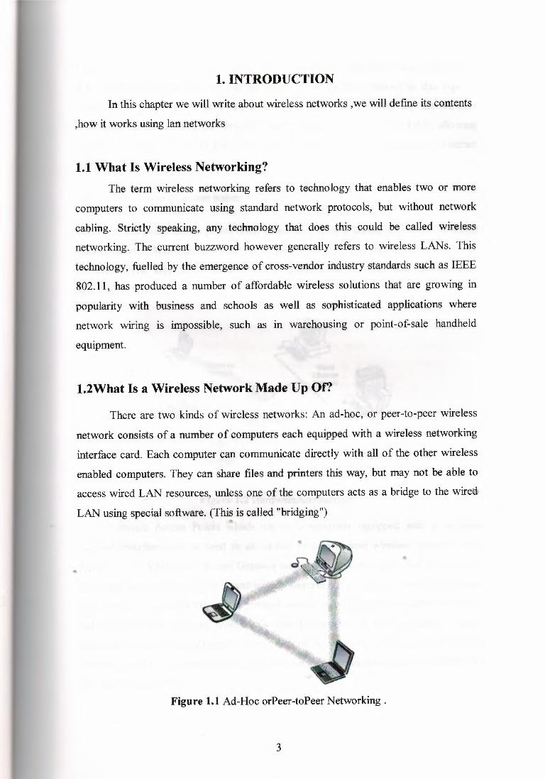
There are two kinds of wireless networks: An ad-hoc, or peer-to-peer wireless
network consists of a number of computers each equipped with a wireless networking
interface card. Each computer can communicate directly with all of the other wireless
enabled computers. They can share files and printers this way, but may not be able to
access wired LAN resources, unless one of the computers acts as a bridge to the wired
LAN using special software. (This is called "bridging")
..
Figure 1.1 Ad-Hoc orPeer-toPeer Networking.
3

Each computer with a wireless interface can communicate directly with all of the others.
b.A wireless network can also use an access point, or base station. In this type of
network the access point acts like a hub, providing connectivity for the wireless
computers. It can connect (or "bridge") the wireless LAN to a wired LAN, allowing
wireless computer access to LAN resources, such as file servers or existing Internet
Connectivity.
There are two types of access points:
Dedicated hardware access points (HAP) such as Lucent's WaveLAN, Apple's Airport
Base Station or WebGear's AviatorPRO. (See Figure 2). Hardware access points offer
comprehensive support of most wireless features, but check your requirements
carefully.
Figure 1.2 HardwareAccessPoint .
Software Access Points which run on a computer equipped with a wireless
•
network interface card as used in an ad-hoc or peer-to-peer wireless network. (See•
•• Figure 3) The Vicomsoft Internet Gateway suites are software routers that can be used
as a basic Software Access Point, and include features not commonly found in hardware
solutions, such as Direct PPPoE support and extensive configuration flexibility, but may
not offer the full range of wireless features defined in the 802.1 1 standard. With
appropriate networking software support, users on the wireless LAN can share files and
printers located on the wired LAN and vice versa. Vicomsoft's solutions support file
sharing using TCP/IP.
4

Figure 1.3 SoftwareAccessPoint.
1.3 IEEE802.11
Wireless networking hardware requires the use of underlying technology that deals
with radio frequencies as well as data transmission. The most widely used standard is
802.11 produced by the Institute of Electrical and Electronic Engineers (IEEE). This is a
standard defining all aspects of Radio Frequency Wireless networking.
1.4 Mix Wireless Equipment from Different Vende
•
Because most wireless networking hardware vendors support the 802.1 1 standard
they can inter operate. However, we recommend verification as the standard is a fairly
recent one, and does specify two different methods for wireless communications; •
Frequency Hopping (FH) and Direct Sequence Spread Spectrum (DSSS or DS), which
are not interoperable.
'Yb-en purchasing wireless networking hardware from 'separate vendors be sure to obtain
guarantees from the vendors that the hardware will interoperate and follows the
standards. •
Within a short time we expect all new wireless cards, like ethernet cards, to become
inexpensive, ubiquitous and totally interoperable. Also of note is that the latest version
of the standard defines 1 Irnbps and 5.5mbps networking, with support for the older
5

standard 1 mbps and 2mbps speeds. This provides some compatibility with different or
older equipment. Note that this new standard covers DS-type Networks, not FH types.
Software access points such as the Internet Gateway which uses the wireless interface of
the host computer should have no compatibility issues with third party wireless
hardware, as long as standards are followed. Typically wireless hardware is identified to
the software as a network interface, and therefore can be used in the same way as any
other network card.
L5 Connect a Wireless LAN with Computers on a Wired LAN
To do this you will need some sort of bridge between the wireless and wired
network. This can be accomplished either with a hardware access point or a software
access point. Hardware access points are available with various types of network
interfaces, such as Ethernet or Token Ring, but typically require extra hardware to be
purchased ifyour networking requirements change.
If networking requirements go beyond just interconnecting a wired network network to
a small wireless network, a software access point may be the best solution. A software
access point does not limit the type or number of network interfaces you use. It may
also allow considerable flexibility in providing access to different network types, such
as different types of Ethernet, Wireless and Token Ring networks. Such connections are
only limited by the number of slots or interfaces in the computer used for this task.
Further to this the software access point may include significant additional features such
as shared Internet access, web caching or content filtering, providing significant benefits
to users and administrators.
••1.6 The Range of a Wireless Network
Each access point has a finite range within which a wireless connection can be
maintained between the client computer and the access point. The actual distance varies
depending upon the environment; manufacturers typically state both indoor and outdoor
ranges to give a reasonable indication of reliable performance. Also it should be noted
that when operating at the limits of range the performance may drop, as the quality of
connection deteriorates and the system compensates.
6
•

Typical indoor ranges are 150-300 feet, but can be shorter if the building construction
interferes with radio transmissions. Longer ranges are possible, but performance will
degrade with distance. Outdoor ranges are quoted up to 1000 feet, but again this
depends upon the environment. There are ways to extend the basic operating range of
Wireless communications, by using more than a single access point or using a wireless
relay /extension point. for further information.
1.7 Wireless Networked Computers Using a Single Access Point
This depends upon the manufacturer. Some hardware access points have a
recommended limit of 1 O, with other more expensive access points supporting up to 100
wireless connections. Using more computers than recommended will cause performance
and reliability to suffer.
Software access points may also impose user limitations, but this depends upon the
specific software, and the host computer's ability to process the required information.
1.8 Use More than One Access Point
Yes, multiple access points can be connected to a wired LAN, or sometimes
even to a second wireless LAN if the access point supports this.
In most cases, separate access points are interconnected via a wired LAN, providing
wireless connectivity in specific areas such as offices or classrooms, but connected to a•main wired LAN for access to network resources, such as file servers. a single area is
too large to be covered by a single access point, then multiple access points or extension
points can be used. -- Note that an "extension point" is not defined in the wireless
standard, but have been developed by some manufacturers. When using multiple access••
points, each access point wireless area should overlap its neighbors. This provides a
seamless area for users to move around in using a feature called "roaming. " (See the
next an explanation ofRoaming). ·
7

Figure 1.4 MultipleAccessPoints .
Some manufacturers produce extension points, which act as wireless relays, extending
the range of a single access point. Multiple extension points can be strung together to
provide wireless access to far away locations from the central access point.
..
•
Figure 1.5 Access Point with an Extension Point .
8

l.9 Roaming
A wireless computer can "roam" from one access point to another, with the
software and hardware maintaining a steady network connection by monitoring the
signal strength from in-range access points and locking on to the one with the best
quality. Usually this is completely transparent to the user; they are not aware that a
different access point is being used from area to area. Some access point configurations
require security authentication when swapping access points, usually in the form of a
password dialog box. Access points are required to have overlapping wireless areas to
achieve this as can be seen in the following diagram:
A user can move from Area 1 to Area 2 transparently. The Wireless networking
hardware automatically swaps to the Access Point with the best signal.
Not all access points are capable of being configured to support roaming. Also of note is
that any access points for a single vendor should be used when implementing roaming,
as there is no official standard for this feature
•
Figure 1.6 Roaming .
1.10 Use a Wireless Network to Interconnect Two LANs
Yes. Wireless networking offers a cost-effective solution to users with difficult
physical installations such as campuses, hospitals or businesses with more than one
location in immediate proximity but separated by public thoroughfare. This type of
9
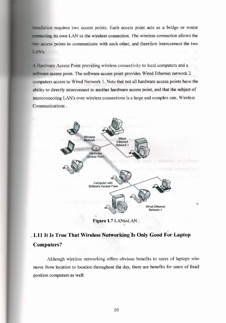
-aııation requires two access points. Each access point acts as a bridge or router
-..ıecting its own LAN to the wireless connection. The wireless connection allows the
access points to communicate with each other, and therefore interconnect the two
Hardware Access Point providing wireless connectivity to local computers and a
rare access point. The software access point provides Wired Ethernet network 2
computers access to Wired Network 1. Note that not all hardware access points have the
ability to directly interconnect to another hardware access point, and that the subject of
interconnecting LAN's over wireless connections is a large and complex one, Wireless
Communications.
1Mred ıEıııemBtıı:eıwoık2
•Figure 1.7 LANtoLAN .
• 1.11 It Is True That Wireless Networking ls Only Good For Laptop
Computers?
Although wireless networking offers obvious benefits to users of laptops who
move from location to location throughout the day, there are benefits for users of fixed
position computers as well:
10

Many schools and businesses have unsuitable building layouts or walls that
cannot be wired for various reasons making it difficult or impossible to build a wired
network. Wireless networking in these environments is a very cost effective alternative
also providing future flexibility. In cases where a small number of computers are
separated from a main network a wireless link may be more cost effective than network
cabling although the latter is perfectly feasible. Temporary wireless LANs can easily be
created for exhibitions, school or business projects, all without any trailing cabling.
1.12Wireless Networking and the Internet
1.12.1 Use A Wireless Network to Share An Internet Connection
Once you realise that wireless cards are analogous to ethernet cards and that
empty space is analogous to ethemet cabling, the answer to this question becomes clear.
To share an Internet connection across a LAN you need two things:
I .an Internet sharing hardware device or software program
2.aLAN
If your LAN is wireless, the same criteria apply. You need a hardware or software
access point and a wireless LAN. Any computer equipped with a wireless network card
running suitable Internet sharing software can be used as a software access point.a
number of vendors offer hardware access points. A hardware access point may provide
Internet Sharing capabilities to Wired LAN computers, but does not usually provide
much flexibility beyond very simple configurations.
..
Figure 1,8 SoftwareAccessPoint •
11

Figure 1.9 HardwareAccessPoint.
1.12.2 Share A Single Internet Connection More Than One Hardware Access Point
If an existing wired LAN already has an Internet connection, then the hardware
access points simply connect to your LAN and allow wireless computers to access the
existing Internet connection in the same way as wired LAN computers.
•
Figure 1.10 MultipleAccessPoints .
12

Figure 1.11 Multiple Access Points .
If there is no existing Internet connection, then this depends on the access point:
Wireless connected computers using Multiple Access Points. All wired and wireless
computers access the Internet through a single software access point. If an access point
provides some form of Internet sharing itself, then having multiple such access points
connected to a wired LAN may require some special configuration, or possibly may
require an additional Internet sharing device or software program.
1.12.3 lfl Use A Wireless Network To Connect To The Internet Does My lsp Need
A wireless network too?
If you use a wireless network to connect to the Internet, the wireless part only
concerns your LAN. The communications link from your LAN to your Internet service. .• provider (ISP) would be identical whether or not you had a wireless network. For
example, if you connected an ethernet network to the Internet via a 56K modem, when
you upgraded your network to use wireless, you would still use the same 56K modem
to connect to the Internet.
13
1.12.4 Can Networking Software İdentify A Wireless Computer İn The Same Way
İt Can İdentify An Ethernet Computer On The Network?
Wireless cards look just like ethemet cards to your network drivers. In fact,
wireless networking cards have unique MAC hardware addresses that are formatted like
ethemet hardware addresses allocated from the same standards organization.
1.13 The Future of Wireless Networks
Wireless LAN sales are said to be approaching the $1 bn mark from a level of
only $157m in 1995. This incredible growth in the market has prompted those
networking manufacturers not currently offering systems to begin developing their own
wireless products. More importantly, it has prompted those already established to begin
research and development into new and improved wireless technologies. Research is
being conducted by large companies such as British Telecom and in Universities
throughout the world. Improved speeds and reliability along with new systems will help
wireless technology maintain a footing in the ever increasing and competitive
networking market. Some of the projects and advancements are discussed below.
The IEEE 802.11 Working Group has set up a study group to develop the
standard in order to take advantage of some the advancements being made in research
and development. Current projects under review include methods of achieving higher
speeds in the current 2.4 GHz band and new systems which operate in the higher 5 GHz
band which hope to yield improved performance. In addition to these, products aı:e
becoming available which use Quadrant Phase Shift Keying (QPSK) and Quadrant"Amplitude Modulation (QAM). These methods, already used in modem technology,
allow a greater number of binary combinations to be represented by a single signal
increasing system performance. Speeds of3.2Mbits/s are capable, compared to 2Mbits/s
with conventional techniques.
The University of San Diego's Centre for Wireless Communication is currently
working on a number of important projects regarding wireless LANs and WANs.
Energy Constrained Wireless Communication is a project designed to investigate
Battery Conservation in the mobile environment. The research revolves around how t~~
14

wireless link can be used most efficiently with close examination of error detection and
recovery to prevent packet retransmission.
Asynchronous Transfer Mode (ATM) networks are rapidly becoming an
important area of network technology and many papers have been written on wireless
ATM. The major ATM standards bodies have yet to define any standards for wireless
ATM. Despite this, several projects have been undertaken by Industry and Education.
Two such projects are WAND (Wireless ATM Network Demonstrator) which aims to
develop a 20Mbit/s ATM air interface in the 17 GHz :frequency and MEDIAN (Wireless
Broadband CPN/LAN for Professional and Residential Multimedia Applications) which
operates at 155Mbit/s in the 60 GHz band.
British Telecom is a large investor in research and development and has done
considerable work in wireless communication. A recent publication has demonstrated
how BT is committed to wireless LANs in the office and home. They have developed a
new type of access point which they have named the 'passive Pico cell'. The Pico cell
emits radio waves which can be used to communicate data over a network; the Pico cell
is connected back to a central network server using fiber optic cables which carry the
radio waves on a carrier pulse of light. This feat is achieved using an alloy based on
indium phosphate which translates radio waves into light and vice versa. The unit has
several advantages, namely that no power is required and the units are small,
inexpensive and maintenance free. The units could cost as little as £35 each and the
technology should be commercially available by 2005.
•
15

2. WİRELESS LAN NETWORKİNG
Wireless LAN is a networking technology that allows the connection of
computers without any wires and cables, mostly using radio and infrared frequency
(RF) technology. It's called LAN because the range targets within an office, a building,
a store, a small campus, or just a house.
2.1 MobilityThe most important benefits of WLAN are flexibility, mobility and portability,
but no industry standard currently addresses the tracking or management of mobile
equipment in its Management Information Base (MIB). This omission would reject
customers from roaming between WLAN AP s that cover a common work area, such as
a complete floor of a building.The manufacture has engineered this problem, offering its own solutions of flexibility
algorithms that facilitate roaming within an IP domain such as a floor with an eye
towards optimizingroaming across IP domains.
Figure 2.1 Handing off the WLAN"ConnectionBetween Aps .••. ,
•• The WLAN equipment can provide customers with connectivity to real-time
information anywhere in their work areas. This flexibility supports productivity and
service opportunities not possible with traditional wired networks. Installation of
WLAN equipment can be fast, easy and can eliminate the need to pull cable through
walls and ceilings.This new equipment enables technology, through a gateway infrastructure deployed in
mobile operator's network; this will bridge the gap between the mobile world and the
intranet, bringing sophisticated solutions to WLAN customers, independent of the
16
bearer and network. When a customer sends data using WLAN equipment, it sends low
energy radio waves to a local antenna site, which connects the customer with the
landlineor wireless location from where the customer is dialing. That same antenna also
sends signals back to the customer wireless equipment. The WLAN equipment has the
ability to move from one area to another within an adequate range. This technology
allows services to derive the function and added value of the WLAN network. There is
a key set of general functions and basis services that must be supported to have a viable
service offering. This key set of functions and services includes the ability for the
customer's computer to register, transmit which is to send, receive, and maintain data
via one or more different media types. These features can be provided to the customer
within a reasonable time if a tactical mission is on the horizon. The RF result is low
power, and works with an AP that sends the radio waves to several customers. High
expand antennas and multiple APs are required to send the signals over thousands of
feet, see figure 2. Handing off the WLAN Connection between APs.
2.2 RangeIn the analysis of WLAN range, there is marginal theoretical difference in the
range capabilities of Frequency Hopping Spread Spectrum (FHSS) and Direct Sequence
Spread Spectrum (DSSS) systems. The largest range difference will be caused by two
sources; the typeand location of the antenna system not the spread spectrum modulation used and the
environment that the equipment is operating in. The antenna diversity is one of the most
important influences on the range and performance of equipment, particularly near the
edge of the range profile, the marginal area. The antenna diversity is the use of multiple
antennas that are physically separated. This is ~one because the radio waves will reflect
off all objects, walls, buildings, bridges, cars, hills, trees, etc and cause nulls and peaks
arbitrarily distributed in the air (OCBN, 2001).
It is significantfor a good path to have a high height for the antenna. Basically, a
better antenna elevation means better connectivity range, with all other things being
equal. An appropriate antenna height would be required to "shoot over" path
obstructions like hills or trees and also to reach suitable "Fresnel" zone permission, see
figure 5 on WLAN frequency & range. This is much the same as the peaks and troughs
17

that are seen on the surface of water when separate waves encounter each other and are
called "Multipath" in the radio environment. With two antennas separated by a quarter
of a wavelength, a few inches for 2.4 GHz band, it is statistically very unlikely that both
antennas will be in a null or wave trough at the same time, whereas a single antenna will
be realistically possible to be in a null in a highly reflective environment, such as an
office building (Proxim, 1998).
Figure 2.2 WLAN Range Between Client And AP .
For a better performance, large antennas placed high above the ground will always
provide better range than small antennas that extend marginally from a Personal
Computer (PC) card and are low down on the side of a notebook computer. The range
of the different equipment components is therefore different. Single PC cards have the
shortest range, 100-500 feet depending on the environment, see figure 3. An AP with
elevated, efficient antennas will achieve up to 3000 feet. Fortunately in most
communication equipment the client card will communicate with an AP and the overall
link will benefit from the better -antenna on the AP, though it will still have a shorter
range than two APs communicatingwith each other.The environment that the equipment is used in has a very significant influence
on the rangeland performance. This should be of a little surprise to everyone that has
used a cordless phone, as they suffer from similar range and performance problems as
WLAN. When the environments outside, in line of sight (LOS), with little to reflect off
and cause multi-path, the range is at its best. When the environment is in a solid walled
building, such as an old stone house or in the building basement, the range is greatly
reduced. This is the same for WLAN; however the multipath problem can significantly
18

ade megabit communications where it will not significantly affect connectivity
quality.Every WLAN configuration is different, when engineering an in-building
solution, varying facility sizes, construction materials, and interior divisions raise a host
of transmission and multipath considerations. When implementing a building-to
building solution, range, physical obstructions between facilities, and number of
transmission points involved must be accounted for. Several factors come into
evaluation when measuring radio transmission range like, transmitter power, receiver
sensitivity, antenna gain, antenna height, RF cable attenuation (RF connection from
transmitter to antenna), and terrain. Since WLAN equipment operates in the 2.4 GHz
band they need a LOS transmission path. The link range will be severely degraded if
trees, hills, walls, heavy fog, or other obstructions are in the radio transmission path. It
is very difficultto predict link range achievement for non-LOS paths.Most office environments are constructed of materials that are relatively "translucent" to
radio waves at 2.4 GHz so the range will not be greatly limited, however they do tend to
present very reflective and refractive environments and the ultimate limitation will
probably be caused by severe multi-path problems. Range up to 80 meters was achieved
in point to multipoint tent configurations. Indoor range is considerably less and depends
on the physical layout. Equipment based on the "Bluetooth" WLAN technology
interferes with IEEE 802.1lb WLAN. For most cases, Germany and European cities in
general, support 2.4 Gbps transmissions to 100 mw:
lOOmw = lmw transmitter* 20 dbi Dish Antenna
lOOmw = 5mw transmitter* 14 or 15dbiYagi Antenna
1 OOmw = 50mw transmitter * 2dbi monopole antenna•
The standard IEEE 802.11b data is encoded using DSSS technology. The DSSS
works by taking a data stream of zeros and ones and modulating it with a second
pattern, the chipping sequence. The standard IEEE 802.11, that sequence is known as
the Barker code, which is an 11-bit sequence (10110111000) that has certain
mathematical properties making it ideal for modulating radio waves. The basic data
stream is exclusive OR'd with the Barker code to generate a series of data objects called
19

hips. Each bit is "encoded" by the 11-bit Barker code, and each group of 11 chips
encodes one bit of data (Conover, 2000).Communication network managers often find that WLAN fall short of expected range.
Even though a vendor's specifications may say that the equipment has a range of 300
feet, obstacles such as walls, desks and filing cabinets can significantly reduce the range
in some directions.This results in an irregular propagation pattern of the radio signal. To provide
adequate radio coverage throughout work areas, communication network manager
needs to perform a RF site survey that determines the number and location of APs, as
well as uncover potential RF interference .
2.3 FrequencyThe FHSS uses a slim band carrier that changes :frequencyin a pattern known to
both transmitter and receiver. Properly synchronized, the net effect is to maintain a
single logical channel. To an unintended receiver, FHSS appears to be short duration
impulsenoise (NDC Communications, 1999).
Rt~l\lil\O Mırıl, flıt!SUJlıll!CtAntenna ('R&lleetsRFwavet:
••Figure 2.3 WLAN RR .
There are two main technologies that are used for WLAN communications
today, RF and infra red (IR). In general they are good for different applications and
have been designed into products that optimize the particular features of advantage. The
RF is very capable of being used for applications where communications are not LOS
and over longer range. The RF signals will travel through walls and communicate where
there is no direct path between the equipment. In order to operate in the license free
20
rtion of the spectrum called the industrial, Scientific and Medical (ISM) band, the
ıadio system must use a modulation technique called Spread Spectrum (SS). In this
mode a radio is required to distribute the signal across the entire spectrum and cannot
remain stable on a single frequency. This is done so that no single customer can
dominate the band and collectivelyall users look like noise (NDC Cornm., 1999).The SS communicationswere developed during World War II by the military for
secure communications links. The fact that such signals appear to be noise in the band
means that they are difficult to find and to jam. This technique lends itself well to the
expected conditions of operation of a real WLAN application in this band and is by its
very nature difficult to intercept, thus increasing security against unauthorized listeners,
see figure 5 for WLAN frequency and range.The WLAN uses RF or IR instead of copper or fiber optic cable to connect
customers together into a LAN. The WLAN is appealing because it allows customer
mobility, flexibilitycan easily be reconfigured, and requires no cable infrastructure. The
WLAN is particularly useful when mobile access to data is necessary, such as in health
care environments and warehouses. It is also appropriate in situations where a
temporary LAN is needed but no communication infrastructure is available, such as
when hosting conferences at hotels or community clubs, or when providing computer
based training in ad-hoc classrooms, exercises, and emergency missions. Frequency
hopping addresses a significant problem with RF "transmission-Multipath" distortion,
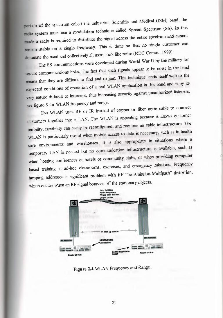
which occurs when an RF signal bounces off the stationary objects.2.4-2ASCllıl_..,.......,AIIMl·-- oııtpıl ,ıwıw
~
•
=
_,,,,_
Figure 2.4 WLAN Frequency and Range .
21
•

A receiving antenna can receive multiple copies of the same signal at slightly
different times, figure 4, WLAN RF, which blurs or smears the signal content causing
bit detection errors. The problem is especially severe in-door where there are numerous
hard, flat surfaces to "bounce" RF signals (Burd, 1998).
2.4 Equipment CostAn analysis reveals savings can be measured in terms of equipment cost for
WLAN compared to what customarily is in used for wired LAN connection. In order for
two customer's to communicate over the wired network, the following are required for
installation, network cable installation with, data drop ($500), PC LAN card ($50), a
hub ($100), small router ($2,500), a network Tl modem ($1,300), and cable conduit
between customer buildings, bringing the total to $9,000. For the WLAN, connecting
two customers to a LAN, the total cost is not more than $7,000 that to includethe bridge
lOOMw output ($1,400), ceiling antenna ($82.00), llMbps DSSS AP ($990) and cable
($120). The big savings is that there is no need to open a trench to bury network cable
beneath the ground, quick installation, and can easily to be removed, see table 1 on
equipment cost, range and performance for three types of WLAN equipment. The
relatively high cost of transmission equipment and licenses makes short wave radio a
rare method for a signal user or company; instead, companies are formed to purchase
and maintain the required licensesand infrastructure (Burd, 1998).Table 2.1 Equipment Cost ,Range And Performance.
Feature Type 1 Type2 Type3
Distance (feet): 500 1000 1000
Meters 150 300 300
Speed/protocol: full duplex 1 O from 4/6 mbps from45mpbsT3 to lOOrnpbs token ring to fullEthernetFDDI AND FAST •
• Ethernet to 155Duplex 1 O MBPS MBPS ATMEthernet
Remote management: no yes yes
List price $us $6.995 $8.995 $16.995
For usual wired LAN connectivity, the immediate cost is high, the installation site
requires extra money compared to the WLAN connectivity, this is not to include the
wired cable is a lease line, and switched line rates, the actual rates for dedicated leased
22

lines may vary from one country to another. In the U.S. the rates are based on range, see
table 2 for leased line rates and table 3 for switched line rates in the U.S .
Table 2.2 Leased Line Rates İn Germany
RangeFirst 100 milesNext 900 mike (101-1000)Each mile over 1000
Rate$2.52 per mile$0.94 per mile$0.58 per mile
TABLE 2 LEASED LINE RATES IN U.S.
Type of ChargeFirst minute of connect timeEach additional minute
!!!!!:$0.60$0.40
Table 3 switched line rates
Line TypeEl speedTl speedFiber 2 strandsDistance 40km
Rate (Year)$87.732$84.264$252.000
One Time Cost$5.000$5.000
Factor in the price of a mobile device plus application software, wireless service,
maintenance and support, each user's tally can reach $3000 annually (Bednarz, 2001).
Table 5 shows the immediate and recurring requirements comparison for two LANs, the
traditional wired LAN and WLAN. The difference between these two LANs is small.
A WLAN implementation includes both infrastructure costs for the Wireless APs and
user costs for the wireless LAN adapters. Infrastructure costs depend mainly on the
number of APs deployed, APs r~ge in price from $800.00 to $2,000.00. The number of
APs typically depends on the required coverage"region and/or the number and types of
•• customers to be supported. The supported area is proportional to the square of th
product range
23

Table 2.3 Two Types Of Lans Comparison
Immediate Reguirements Wired LAN WLAN
Equipment upgrades: X X
Documentation: X X
Site preparation (AC.raised floor.Etc...) X --Hardware installation: X X
Installation applications: XX
Testing: X X
Training X X
Installation of cabling: X --Equipment software installation X X
Creating user environments: X X
Space required for new equipment: X -·
Supplies and spares: X X
Backup: X X
Recurring reguirements:LAN management: X
X
Consumable supplies: XX
Hardware and software maintenance: X X
Training XX
2.5 Equipment Bandwidth and PerformanceThe WLAN protocol is engineered to reduce the demanded bandwidth and
maximize the number of wireless network types that can deliver. Multiple WLAN
networks within an area can be achieved, with the additional aim of multiple networks.
In other words, an IP-networked world will enable the multimedia evolution to optimize
the bandwidth required to support the multimedia applications demanded by the
marketplace. This will reduce the cost to own or lease a dedicated LAN circuit. The
WLAN equipment can go point-to-point (PPP), speed up to 100MB at range of 3000
meters. The WLAN equipment speed is adequate among customers to send and receive,.
e-mail messages, upload and download documents (PowerPoint briefing slides,
spreadsheet, etc.) and small data files, see ·table 1 equipment cost, range and
performance for WLAN performance.The ISM spread spectrum bands do not offer a great deal of bandwidth, keeping data
rates lower than desired for some applications. The IEEE 802.11 working group,
however, dealt with methods to compress transmission data, making the best use of
available bandwidth. Efforts are also underway to increase the data rate of 802.11 to
accommodate the growing need for exchanging larger and larger bandwidths .
24

The standard for WLAN networks is IEEE 802.11 b. The 802.11 b standard specifies the
use of DSSS in the 2.4 GHz band. Most European countries have a maximum of 1 OOmw
power output. The data communications rate for this standard is at 1 and 2 Mbps. The
802.11 b high-rate (HR) Wi-Fi version of the standard increases the throughput to 11
Mbps but the same power maximum applies in Europe. The WLAN equipment can
theoretically support up to 200 customers. Table 7 compares the conventional wired
LAN and WLAN. The evaluation performance rates criteria on a scale of 1 to 5, with 1
being best.Table 2.4 Types Of Media.
Type of MediaTwisted pair-unshielded/shieldedCoaxial cable-base band/broadbandSatellite/terrestrial microwaveWireless LANInfrared LANFiber optic cable
Maximum BPS (Kilobits per Sec)2m-100m (million)264m-550m (million)100m (million)3.3m (million)4m (million)40G (billion)
CRITERIANumber of workstations:Initial cost:Personnel costs:
Figure 2 .• 5 WLAN Performance
WtANga\rıseWEEKLab'&~ehttı._ !lıill l!0'2.11a,!!ıned ,ıfm'icelı aı..- Iii··- - 11...-,-. t1t.l>öMrdo-.wıme ııı,aı.ıgh aveıııoııı ~5M bl)ı-
-------
Table 2.5 LANs Comparison
WIRED LAN1455Operations/maintenance costs:
25
WLAN4212

The "Multipath" Fading problem is caused by a signal bouncing off the walls and other
surfaces, as the signal arrives at the receiver, a reflection of the signal will arrive shortly
afterwards. This causes interference as old signals arrive at the same time as the new
data. Frequency hopping equipment is protected from this problem since a reflected
signal arrives after the receiver has hopped to a new frequency and any signal on the old
frequency is ignored. Direct sequence systems do not have this advantage, however a
technique identified as antenna diversity allows them to show some improvement.
Antenna diversity involves having two antennas built into the hardware. Two antennas
allow the equipment to determine which signal is stronger (Canterbury Campus, 2001).
Table 8 displays the IEEE series topologies and protocols:
Table 2.6 IEEE Series Comparison
CRITERIASpeed:Medium:
IEEE 802.310.100.1 OOOmpbstwisted -pair wiresCoaxial cable, fiber optic500m for thick tableUp to 1000m185m for thin-net cableUp to 2500mW/repeaters802.3-100 per thick
IEEE802.54.16.100 Mpbstwisted -pair wires
IEEE802.llvarywireless
Range: 366m for the main ring
7sow/repeaters4000m fiber optic
260 200NumberOf stationsCost forNicandConnectorsOnly:
$30 per thin-net$50 per station $225 per station NIA
2.6 Equipment Procurement and InstallationIn view of wireless technology, cost reductions of network components will be
possible compared to alternative technologies like traditional wired LAN. Cards that
plug into PC or laptop are promptly available, and operate either Peer-to-Peer or Peer
to-AP Mode. The WLAN equipment can be configured in a matter of hours while
customarily used equipment (hard wire) can take a week to a month if cable between
customers is not available. For scalability, WLAN can be installed and configured in a
variety of topologies to meet the needs of specific applications and installations, see
figure 7 on vendor equipment.
26

Table 2.7 WLAN vendors
V P'Clı.1CIJ.\'lı;• ill II cıımplusl
l!Ml,._p, ,nW ""'4ılı·a [BA ani V S4.S.-
2:ı..ftry, ın'W "4ılnPCWı::IA 111Typ• 11
15-chumRıb...
£ıiwlL r•~.AN21i<ll lı.,nıı.po lı.ıo .,!A' ltSO,u 1)00"' I lBAn,·d I 111ö.ın
?11)018.\
ll•nı...J'.ı\lı2~ lı.6 l.lhpıı lı.ıuı.,w tso .• l)ı)(ı r• I ·r;)';.~·~; Il!ıiwıL HOJı')tfC! ,111
Cınd.I lııntiııııau
The WLAN configurations are easily changed and range from peer-to-peer
networks suitable fur a small number of customers to full infrastructure networks of
thousands of customers that enable roaming over a broad area, as used in several U.S
airports and hospitals. Micro cells (the physical areas covered by each of the LAN AP)
are established to provide coverage to all customers, figure 8 shows a notional WLAN
configuration.
II a
Figure 2.6 WLAN Configuration.
The range a WLAN can be from a LAN AP depends on many factors including the
types and numbers of obstructions (such as walls, hills, trees, etc.), the data rate, and the
equipment used.
27

The LAN AP serves as the LAN hub for the WLAN customers and as connection points
into normal building LANs. Each LAN AP typically supports large number of
customers, depending upon their network use.A variety of factors must be considered when selecting type equipment for LAN
connectivity. The company should decide whether a wired LAN is required or an
alternative like WLAN will be sufficient. Factors, which must be considered, include
cost- effectiveness, hardware, application software, security, training, etc. The weight
associated with each selection criterion may differ among companies. In making the
right selection, company management and IT analysts need to evaluate the alternatives
from the perspective of their companies' immediate short-term and long-term
communication objectives, see evaluation criteria below.Table 2.8 Criteria Selection .
CRITERIA WLAN OTHERS
Cost: $8.995 $6.548
Number of concurrent users: 8 6
Medium: yes no
Expandability: yes yes
Software and hardware: yes no
Number of work stations: 10 5
Type of use:Mobility and flexibility: yes yes
Speed: to much very much
Vendor on site: yes no
Applications: ---Security: yes no
Range: 1000 z 2000 Hz
Frequency: 1000MHz 2000MHz •
.-~~I
'.:ı
2:1 SecurityThe WLAN service cannot be perfectly secured, but the wireless industry has
made significant investments to prevent intruders and hackers. The WLAN equipment
can support session layer protocols that establish the connection between applications,
enforces rules for carrying on the dialogue, and tries to re-establish the connection if a
failure occurs. The WLAN manufacturing companies claim that the current IEEE
28

12.11b standard contains an optional 40- bit encryption algorithm to ensure data sent
ver the air is scrambledand remains private.small research group at the University of California at Berkeley in recent times put
out a statement stating that they found flaws in the. IEEE 802.11 standard (and IEEE
802.11b standard). Their statement says that they were able to intercept transmissions
over the wireless network. These transmissions were encrypted, but the encryption was
broken (Dunne, 2001).
A company may implement WLAN for the customer's specific requirement; however,
WLAN security is the most serious issue that a customer must consider. Most WLAN
circuits enter European controlled areas; non-secure encryption device is a requirement.
Throughput is the next most critical WLAN issue. WLAN should not be used for
critical data transfer without a study on the maximum throughput requirement. The
WLAN technology is considered an emerging technology, and therefore should be
approached with caution. The technology is largely untested for the secure environment,
and it introduces a potential for operational data-loss and yet-unknown security risks.
As with wired networks, the first line of security defense is the customer IDs and
passwords in the operating system of client computers and servers. Additional security
varies from one AP to another.Many AP manufacturers allow network administrators to limit AP connections by
creating a table of wireless client hardware media açcess control (MAC) addresses, see
figure 9 above on MAC layer. There is no WLAN solution exists for sensitive data
processing. Also, before any wireless equipment is procured or operated in Europe, the
customer must verify that the specific wireless equipment used has host-nation approval
to be used in the country where the LAN is to be set up. Although WLAN is a part of
the Information Systems Architecture (ISA), there are numerous procedural guidelines
processes that must be completed before they can be implemented;host-nation approval
ı·~ı
29

required for any wireless application. Host-nation vendor equipment that is used out-
f-the-box by anyone must be approved before use for company applications.
The WLAN is still considered an emerging technology. Several technologies (Fast
Ethernet-Gig E, Cell Telecommunications) are in competition with this new technology
and it is not determined that this technology wins out in any particular situation. It has
promise and with faster data rates and longer reliable operating distance. This new
technology may become a more important player as these characteristics improve. All
new implementations must meet minimum current standards of 3DES for security and
l OOmw at 2.4 GHz frequency requirements.
The WLAN can't send or receive signals over much larger areas than that of traditional
wired media such as twisted-pair, coaxial cable, and optical fiber optic (FO). In terms of
privacy, therefore, the WLAN have a much larger area to protect. To utilize security, the
IEEE 802.llgroup has to organize their work with the IEEE 802.10 standards
committee accountable for developing security mechanisms for all IEEE 802 LAN
series . Security mechanisms in IEEE 802.11b networks should be equivalent to existing
mechanisms in wire-based networks. Traditional wired network jacks are located in
buildings already protected from unauthorized access through the use of keys, badge
access, facial recognition, finger printing and so forth. A customer must gain physical
access to the network building in order to plug a client computer into a network jack. In
contrast, a WLAN AP that is configured incorrectly may be accessed from off the
grounds (for instance, from a parking lot next to the building). Properly designed
WLAN secure access to the APs and isolate the APs from the internal private network
prior to user authentication into th: company network domain .Empowering Empowering the customer with the ability to access a large quantity of.information and services from WLAN equipment will create a new battleground. The~ ..WLAN industry will fight to provide their customers with sophisticated and value
added services. As WLAN technology becomes a more secure and trusted channel by
which customers may conduct their financial affairs, the market for WLAN will become
even more lucrative.
,ı"
,I
30
2.8 Wireless LAN ApplicalionsBelow are given a few examples of how Wireless LANs can be very useful and
important in various fields. These examples illustrate the many uses of Wireless LANs
in health care, education and research.
2.8.lHealth Care
When disaster strikes, the American Red Cross Disaster Service operates like a
huge mobile warehouse, setting up, on a moment's notice, locations for receiving and
storing thousands of pallets of food, supplies and equipment, and efficiently distributing
those supplies to disaster victims. These operations often take place under extreme
conditions: heavy storms, power and telephone outages, continuing floods and other
logistical difficulties posed by the preceding destruction. Field houses for relief
operations must be swiftly set up and often moved during the course of the operation.
When relief needs have been met, they must be shut down quickly and the equipment
made ready for immediate deployment to a new disaster site. Voice and data
communications are critical to the Red Cross operations and wireless solutions are a
natural choice.Prior to adopting a wireless application, the American Red Cross used paper-based
inventory systems. Richard Hoffman, senior systems programmer with the American
Red Cross National Headquarters, said recent disasters demonstrated the need for a high
capacity, automated system the primary requirements for the new system were mobility,
reliability, ease-of-use by staff and volunteer workers, and the ability to provide six to
eight hours of continuous battery operation in the event of a power failure. Secondar;,;
requirements included tight tracking of accounting and traceability records of materials"
,,
and donated goods used during the operation, in order to meet IRS tracking*
requirements. The system tracks everything from perishables and water to equipment
such as fax machines, cellular phones and tables ancl chairs. The system also maintains
warehouse data and transmits that data to a central logistics database at the local disaster
operational headquarters. (The Red Cross central logistics database enables it to provide
a current inventory of all relief material on hand for the entire operation.).
2.8.2 Education and Research
Wireless Andrew is a 2Mbit/s wireless local area network connected through
access points to the wired Andrew network, a high-speed Ethernet backbone linking
31

buildings across the Carnegie Mellon campus. The combination of networks gives high
speed access to any user with a portable computer and a wireless LAN card from any
building covered by access points. In addition, a low-bandwidth wide area network that
covers the greater Pittsburgh area provides researchers and others with off-campus
wireless access to campus networks. Campus network services include e-mail and file
transfer, access to audio and image data, access to the library and other databases, and
full Internet access.The Institute's wireless initiative not only serves the campus community by increasing
high-speed access to campus networks, it also provides an infrastructure for research in
wireless communication. As the university's Dr. Ben Bennington points out, "What
makes us different from other wireless technology customers is that we're not
implementingan application; we're implementing infrastructure, a kind of 'honey pot' to
attract people to mobilityresearch".In the area of infrastructure, Carnegie Mellon has anticipated the need for the next
generation of systems to integrate wired and wireless networks by giving researchers a
platform for developing and testing "middleware" - software that allows seamless
access to the various wired and wireless networks which a roaming computer
encounters. As for mobility research, the system will provide a major test bed for
Carnegie Mellon and its sponsors, giving researchers in many fields, inside and outside
the university, a way to explore the uses of mobile computing. Programs include
systems research, development of computer platforms for mobile use, compression
research, and research on the human factors of mobile computing. The Institute's
ongoing development is resulting in numerous innovative uses of wireless LANs:
including emergency response, health care, and vehicle maintenance. One project
involves communication with trains to download diagnostic data. Another involves."wearable computers" - a project for developing innovative maintenance systems that
free technicians' hands while still giving them access to engineering drawings and other
information. Benefits: Increased Access to Campus Networks and Creation of Leading
Research Platform.
32

9Analysis
9.lAdvantages• The WLAN Internet connectivity is great for any company whose site is not
conducive to LAN wiring because of building or budget limitations, such as older
buildings,leased space, or temporary sites.• While the initial investment required for WLAN hardware can be higher than
the cost of traditional wired LAN hardware, overall installation expenses and life-cycle
costs can be significantly lower. Long-term cost benefits are greatest in dynamic
environmentsrequiring :frequentmoves and changes.• The WLAN concept ensures the Internet customer, web-served mobile
communication and field service productivity, the benefits of wireless communications
sooner, and hard dollar savings quicker than from any other commercial equipment
available today. WLAN can provide network hardware for in-building and building-to
building data networks, as well as mobile communication equipment for information
capture and display.• WLAN mobility, i.e., a student attending class on a campus accesses the
Internet, accesses information, information exchanges, and learning.• Senior executive officers, managers can present their briefings using WLAN
without carrying the data files, charts, and any storage equipment.• Trade show and branch office workers minimize setup requirements with
central database thereby increasingproductivity.• Most WLAN equipment is plug-and-play. This will help to reduce the total
ı-ıı,:I
,,
"'cost to include vendor technical installation, equipment maintenance and to eliminate
equipment redundancy in case of system crash.• • WLAN technology allows the network to go where regular wire cannot go.
• The WLAN was clearlybetter then wired in setup/teardown time and effort.
2.9.2 Disadvantages• Due to the limited bandwidth, the WLAN technology cannot support Video
teleconference (VTC). However, experts believe that WLAN will support VTC within
the next five years.
33

• Due to the security reason, using the WLAN equipment as a contingency
model s not recommended.• The WLAN operated within typical wired LAN parameters provides less
downtime and n increased invisibility to the customer., \_~~ ~~ \~"~~\~~ 'o.\~Q R'o.\(~ QtWlGUS "QOtentials in customer mobility and
configuration changes significantly worse then wired in the risk of jamming, in the
Potential or interference and in the detection of customer location.• The WLAN is not capable to download and upload large data files.
• The WLAN is significantlyworse then wired in the risk of jamming, potential
for inference,and in the detection ofRF signal.• Products from different WLAN manufacturers are often incompatible with
each other.• Interference from :friendly network will likely effect WLAN operation as the
popularity of this industry increases.• The WLAN equipment is not capable of sending and receiving data
successfullyduring Field exercises in case ofheavy fog or dust storm.• The WLAN equipment has difficulties at time in sending and receiving data
when a Flyingobject passes over a WLAN field exercise.• If too many people or businesses in the same area have WLAN, then the band
of air that they transmit signals on can become overloaded. Problems with signal
interference are Already happening and there are no doubts that the airwaves will
become overloaded (Dunne, 2001).• Most office environment and modem homes are constructed of materials that
are relatively '"translucent" to radio waves at 2.4 GHz so the range will not be greatly"
,,,,/
limited, however they do tend to present very reflective and refractive environments and.the ultimate limitationswill probably be caused by severe "multipath" problems.
• The problem has been the lack of interoper~bilityamong WLAN products from
different manufacturers. The classic Ethernet 802.11 standard was ignored in
developing current WLAN products (Seymour 2000).• The WLAN weakness is susceptibility to many forms of external interface and
the cost of transmitting stations. In addition, United States, international authorities and
treaties strictly regulate most of the bands that can support high-speed communication.
Use of these bands requires an expensive license (Burd, 1998).
Conclusion
34
10 Future of "\\!LANWireless data tietworks have been with us, in one shape or another for over ten
years. Only in the last four years. however, have they become noticed in the wider
market place and as a fesult of this; become more common. They are beginning to move
from the specialized v@?eal markets to the broader and more profitable mass markets
of local area networas, One case, which would support this trend, is the recent
acquisition of Net fwave by Bay Nortel. ~fJY Nortel, a large and well-established
network equipment manufactures-has realized the growth potential in the wireless
network market. Perhaps the -~,gest contributing factors to this trend have been the
ratificationof wireless netwcımstandards and the availabilityof the ISM band.
',,I••
..
35
3. WIRELESS APPLICATION PROTOCOL
In this chapter we will discuss of the wireless network useful application, it is
wireless application protocol we will study one of its useful application.
3.1 What Is WAP?The WAP (Wireless Application protocol) is a specification for a set of
communications protocols to standardise the way that wireless devices, such as cellular
telephones and radio transceivers, can be used for Internet access, including the e-mail,
the World Wide Web, newsgroups, and Internet relay chat. While Internet access has
been possible in the past, different manufactures have used different technologies. In the
future, devices and service systems that use WAP will be able to interoperate."
WAP is a technology designed to provide users of mobile terminals with rapid and
efficient access to the Internet. WAP is a protocol optimised, not only for the use on the
narrow band radio channels used by second generation digital wireless systems but also
for the limited display capabilities and functionality of the display systems used by
today's mobile terminals. WAP integrates telephony services with micro browsing and
enables easy-to-use interactive Internet access from a wireless device. Common WAP
applications, which are already available to users today, include many forms of on-line
banking, various informationpoints and messaging.
Wireless devices such as mobile phones have become very popular in recent
years. To coin a phase "mobile phones are no longer just phones"; they are
communication devices capable of running applications and communicating with other
devices and applications over a wireless network. WAP is developed to be the standard
means of information transportation and Internet service gateway for mobile
communication services. WAP is unique in that its hardware; software platform and"
network are independent. It uses a lightweight browser, a client server that can be.designed to have minimal footprint and hardware requirements to fit in with a wide
• range of different devices.
3.2 A Wireless Application - Student Service
The author of this thesis recognised that people not only value the power and
usefulness of the web but also wanted to have it available while away from home or
work. The hegemony or dominant ideology behind this study is simple: someone with a
cell phone, pager, or PDA should be able to do limited web surfing, for example to
make reservations, to purchase tickets, or to access bank accounts. But how can a small
36

ice with a small display render web pages that contain large amounts of text? And
who wants to wait for long periods of time for a huge image to be sent over a slow
wireless link? And how can a user follow links without a mouse? The answer to all
these questions is answered throughout this thesis and the actual physical working of
these problems and the fundamental technologies of WAP are evident in the application,
whichhas been designed by the author.For the purpose of this study the author has implemented an in-depth student
service. The theory behind this application means that it can be customised to bring any
type of information to specific users. Those interested in sport will be able to read the
latest results and those interested in :finding out what is happening around the globe will
be able to catch up on world news. With the potential that WAP offers, it is not beyond
the realms of possibilities that mobile devices will be essential for us to conduct our
everyday lives. If this scenario does pan out, then all types of people will use
applications such as this for various purposes. The author's application will allow
students with WAP compatible devices to gain access to university news. By a simple
click of a button on a mobile device, students will be able to gain information and
relevant news regarding events taking place in the university within the immediate
future.
,q,ı, ..
Much thought went into the type of application that was to be designed.
However due to the fact that the :final product would be displayed on a simulator it
became apparent that in order to design such an application it would be necessary to
incorporate all of the primary teachings of WAP.
- The actual setting up of a site.- The workings of the WirelessMark-up Language.
••
"- The architecture of the WAP environment.- And how to travel from page to page, or card to card as it's called within the
field ofW AP .After endless research and providing the necessary background on this topic the
author had to construct a "water tight" methodology. The main tool necessary for
creating a WAP application is a Software Development Kit (SDK). There are many of
these availabl to new developers from various sites such as
http://www.wapnet.com/demo/democont.aspand,http://www.forum.nokia.com.
However for the purpose of this study the author decided upon version 4.0 for WML
37

available from the phone.com web-site 11• The primary reason for this decision was
because the majority of others required Windows NT in order to download the
necessary software and this package was not available to the author. A more detailed
description of the methodology will be discussed in chapter 3.Chapter 6 will evaluate both the successfulness of the student service as an
application and the successfulnessof the author's study within the realms of WAP.
3.3 Literary ReviewDue to the fact that WAP is in its stage of infancy, there is very little
documented information and so a great deal of background knowledge was obtained
from relevant web sites and companies who are involved in developing WAP
applications. As a result this literary review will include the practices and teachings of
the main forerunners within the field of wireless devices, this will include companies
such as Nokia 'and phone.com', and more importantly a group known as WAP forum'.
It is safe to say, that the WAP forum is driving the development of WAP, and
that it is in fact the engine behind this relatively new application. . The forum was
initially founded by Motorola, Nokia, Ericsson and phone.com (previously unwired
planet). Since it's inception the WAP forum has grown dramatically and now comprises
of over 170 full members drawn from the world's leading telecommunications and
software companies. The underlying belief of the forum is that WAP is a technology,
designed to provide users of mobile terminals with rapid and efficient access to the
Internet. WAP is a protocol optimised, not only for the use on the narrow band radio
channels used in second generation digital wireless systems but also for the limite
display systems used by today's mobile terminals. WAP integrates telephony services,.,,
'1'1,lı·ı
with micro browsing and enables easy-to-use interactive Internet access from the mobile.handset. The forum believes that WAP will enable operators to develop innovative
services to provide differentiationin competitive market environments. •The WAP forum represents "the de facto world-wide standard for providing
Internet communications and advanced telephony services on digital mobile phones,
pagers, personal digital assistants and other wireless terminals".
1 http://www.phone.com1 http://www.nokia.com2 http://www.phone.com3 http:/lwww.wapforum.com
38
In order to place the significance of the forum in relation to this thesis, one must realise
that the forum members represent over 90% of the global handset market, carriers with
more than 100 million subscribers, leading infrastructure providers, software developers
and other organisations providing solutions to the wireless industry. The author fully
appreciated that it would be both detrimental and naive, to even begin an individual
study, without first gaining an insight into the beliefs and teachings of the WAP forum.
3.4 The Goals Of WAP Forum
To become independent ofwireless network standard.
To provide access to all.To submit specifications for adoption by appropriate industry and standards
Bodies.Applications scale across transport options. To create a global wireless
protocol specificationto work across differingwireless network technologies.
To enable applications to scale across a variety of transport options and device
types.Extensible over time too new networks and transports.
3.5 Benefits Of WAPThere are various benefits for using WAP, in the same way that there are various
groups that will benefit from using WAP, from operators to users and from
manufacturers to developers.
~For wireless network operators WAP will cut costs and increase revenues by
both improving existing services such as interfaces to voice mail and prepaid systems,
and facilitating new value-added services such as account management and billing
ınquıres.
End users of WAP will benefit from easy, secure access to relevant Internet
information and services such as messaging, banking and entertainment through their
mobile device. On a smaller scale Intranet information such as corporate databases can
also be accessed via WAP technology.
39

For manufacturers the global open standard provides endless scope for new
product and marketing opportunities. And for developers, the simple fact that there are
well over 100 million compatible devices worldwide makes it clearly obvious the
significantrevenue that is availableto developers.These goals and benefits represent the dominant ideology behind WAP
applications and the formation of the WAP forum. Considering that the forum has over
95% of the wireless industry supporting it, it became obviously apparent that
concentrating this literary review on the WAP forum was a necessity, in order to gain an
insight into the technology and strategies required to develop, deploy and support
wireless application.
"'
:.::~
•
40

4. THE ARCIDTECTURE AND WORKINGS OF WAP.
Before one could possibly consider discussing how to design a WAP
application, it is vitally necessary to first provide a detailed analysis of the practicalities
and actual architecture of WAP. Due to the fact that this type of architecture is
something that many people are not familiar with, and can therefore prove to be
extremely complicated, the author decided not only to document this section but also to
depict simple diagrams in order to provide a working knowledge of the WAP
environment. The author deems that only once a working knowledge of this
environment is established, would it be suitable to continue and discuss the design and
implementationof his own application.Despite the explosive growth of wireless networks, the wireless Internet, has not
yet taken off. There are many reasons for this, both technical and non-technical.
However from a technical perspective, the adoption of the wireless Internet has been
limited by two primary characteristics; the capabilities of hand held devices and
wireless networks. When hand held devices enter the Internet space, the gap between
Internet client capabilities widens. This makes it difficult for servers to provide a level
of service that is appropriate for every client. Most web servers fail to recognise that
computers are no longer all wired and connected to high-speed networks.WAP specifies two essential elements of wireless communication: an end-to-end
application protocol and an application environment based on a browser. The
application protocol is a layer communicationprotocol that is embedded in each WAP -
enabled device. The network side includes a server component implementing the other
end of the protocol that is capable of communicatingwith any WAP user agents. •
4.1 Background
••Due to the fact that mobile phones were unheard off 20 'Years ago, it is
understandable that the technology developed for the Internet was designed for
desktop and larger computers. These computers had generally medium to high
bandwidth and reliable data networks. Whereas wireless devices present a more
constrained computing environment. His key limitationsofwireless devices include:
less powerful CPUs,
Less memory,Restricted power consumption,
41

Smaller displays,
Different input devices.
Further more due to the limitations with power on wireless devices, data networks
also presents a more constrained communication environment. These limitations include
less bandwidth, more latency, and less connection stability.
4.2 Network OperatorsAs the number of wireless devices and the demand for them increases, operators
must be looking to provide more advanced and usable services. The operators must look
to achieve this by addressing these followingareas:
Interoperable - terminals for different manufacturers communicate with
different services in the mobile network.Scaleable - mobile network operators are able to scale services to customer
needs.Efficient - provides quality of service suited to the behaviour and
characteristics of the mobile network.Reliable - provides a consistent and predictable platform for deploying
services.Secure - enables services to be extended over potentially.
A more technical and in-depth analysis of the actual workings and architecture of
the Wireless Application Protocol are now offered by the author, so as one can
understand not only how to develop an application, but also to understand exactly how a
WAP application works.
4.3 Components Of WAP Architecture-And It's Basic Workings
• Just like an engine has vital parts, and the body has vital organs, WAP has vital
components, which are a necessity in order to function properly. The first of these is the
WAP gateway. The gateway is a telecommunications software infrastructure that
provides an interface between telecommunications protocols within the mobile
operator's network and Internet protocols.The second major component is the origin server; this is a computer, which
stores WAP content. The origin server communicates with the WAP gateway over the
42

HTTP protocol so it can be on a local network or anywhere on the Internet. Current web
servers are capable of storing WML, WML Script and Wireless Bitmaps.
The third component is the wireless telephony application server. This provides
an interface between the WAP gateway and other infrastructure elements of the mobile
operator's network. The WT A server can also be used to provide a WAP front end to
existing applications such as prepaid billing.And finally we have the terminal device. This cart vary from a pocket pager to a
palm top computer. As long as the device comes complete with a WAP micro-browser
and connection to a WAP gateway. The author has decided to concentrate on one of
these devices, the mobile phone.4.3.1 How A Wap Applicatıon Runs Between Clıent And Server.
As this is a relatively new concept for many, the author has decided to explain this
somewhat complicated process, with the aid of a diagram in order to provide a more
simplisticoverview.
WML
Proxy,..... -
WirelessNetwork
•
WebServer
FilterWTAServer
WAPProxy
••
Figure 4.1 Wap Model
Applications are written in the wireless mark-up language (WML), and stored on..either a normal web server or directly on the WAP gateway. The content stored on the. -web server will be accessible from the client device via the cellular network and a WAP
gateway or proxy, (the WAP proxy acts as the gateway between the cellular network
and the Inter/Intranet). This is when the WAP technology kicks in, any application
written in HTML will have to be converted to WML before they are sent to the client
device, this is carried out by the HTML filter which can form either part of the web
server or the WAP gateway. The data sent by the origin server and the handset is binary
encoded to optimise transmission over the narrow bandwidth of the cellularnetwork.
43

4.3.2 So How Do These Components Work Together?
Surprisingly we all know more about the workings of WAP than we actually
think; this is because it works on the same fundamentals as that of the Web. In as much
to say that, a user makes a request for information using a URL. This URL is presented
in the form of a hyperlink, then the information is retrieved and presented to the user.
This means that at either end of the WAP system is a user and content. To apply this
theory to the author's application, a person uses a mobile phone to make a request and
to view the content.However there are two ways of retrieving the content for the user. Firstly the
information can be retrieved direct from a WAP server, the user simply requests content
from the server, the server retrieves the content, and the content is then returned to the
device. The second method is slightly more intricate in that the client device is in
communication with a "WAP gateway". The client device requests the content from the
gateway, the gateway retrieves the content, reformats it, and then the content is returned
to the device. One must understand that the WAP gateway translates WAP messages
into another protocol, such as HTTP. However it is not possible for the author of this
study to demonstrate the latter of these practices as the technical software necessary for
such an application is only available to large companies interested in this field ofstudy.
,,,ı
~I
•'
4.4 WAP System ArchitectureBefore one can design a wireless application a complete understanding of both
the internal and external architecture is extremely necessary, that is why the author has
decided to allocate an entire chapter fo this topic.
Many people understandably assume that WAP is a single protocol, but in
actual fact it consists of a stack of protocols that provide different layers that are
necessary to design an application.
44

WAEAPI-
User Ageınt Layerı, WML Brıwım I WMlScıipt WMLS(;ript'\llrtual MaclıiıM: UbraritS
URL & HTTP Layer I URL Loader I 'I WSP Htaıtc:ı tbrıdfü:ıg I I HTIPloadt:r I I Caclıt' II \lo'SP Adaptu I !
!Protocol layer Wireless Pn,tocol Stııck
,.a:
WSPWTPlıVTlS
WOP
TWDP API (Bearen).___
Fıgure 4.l The Wap Protocol Stack.
The light weight WAP protocol stack is designed to minimise that required
bandwidth and maximise the number ofwireless network types that can deliver WAP
content - GSM, SMS, USSD, CSD, GRPS, and CDMA. Since WAP is based on a
scalable, layered architecture, each layer can develop independently of the others.
This makes it possible to switch onto new bearers, to use new transport protocols,
without major changes in the other layers.
..
The WAP layered architecture enables other services and applications to utilise"the features of the WAP stack through various interfaces. External applications may
¥
access the session, transaction, security and transport layers directly. In order to
analyse the WAP stack, the author has decided t~ discuss each layer"individually.
Wireless Application Environment: a lightweight application environment based on
browser technology with mark-up and script capabilities and telephony awareness.
Session Layer: provides communication session services for the application
environment.
Transaction Layer: a lightweight reliabilitylayer suited to request/response applications.
Security Layer: authentication and data encryption function.
45

Transport Layer: basic communicationsdata mover function.
Network Layer: bearer services and the physical network type.
4.4.1 WIRELESS APPLICATION ENVIRONMENT (WAE)
The Wireless Application Environment (WAE) offers the software platform
environment for the application software. It's based on a combination of World Wide
Web (WWW) and mobile telephony technologies. The WAE aims to establish an
interoperable environment that will allow operators and service providers to build
applications and services that can reach a wide variety of different wireless platforms.
WAE is built into the so-called micro browser program that works in a very similarway
to normal WWW browsers which we all know interprets Hyper Text Mark-up
Language (HTML) and JavaScript, for use on desktop devices. WAE consists of
Wireless Mark-up Language (WML), WML Script, and Wireless Telephony
Application (WTA).
WML is a lightweight mark-up language, similar to HTML, but designed for
use on hand held mobile devices.WML Script is a lightweight scripting language, similarto JavaScript
WTA includes telephony services and programming interfaces.
A more detailed description of WML and WML Script is provided by the author, and
is located in its own subsection at the end of this chapter.
4.4.2 Wireless Session Layer (WSP)
The session layer of the WAP architecture consists of the Wireless Session
Protocol (WSP) and Wireless ,,,Transport Layer Security (WTLS). They provide
connection-based services to the application layer, WAE and WTA. Basically a session,.is started, content is exchanged, and the session is later closed. Also the session can be. ,,,.
• suspended and resumed. WSP is the WAP equivalent of HTTP. Within HTTP and WSP
is the concept of request and reply, each consisting of a header and a body. The header
is data about the data and consists of information about the particular request or
response; the body consists of WML, WML Script or images. WSP also defines a server
"push" transaction where the server sends unrequited info to a client device. This
service can include services such as up to the moment sports results, and can be tailored
for each individual.
46
4.4.3 Wireless Transaction Layer (WTP)
The Wireless Transaction protocol (WTP) works between the WSP and the
security layer (WTLS). What the WTP actually does is reducing data packets into lower
level datagram's and transforms them in useful data. WTP also keeps track of received
and sent packages and does acknowledgement sending when needed.
4.4.4 Security Layer (WTLS)Wireless Transport Layer Security Protocol (WTLS) is made up off all the
cryptography orientated features of WAP. This includes crypting , decrypting, user
authentications and data integrity checking. WTLS is the WAP equivalent of the HTTP
SSL or TLS.
4.4.5 Transport Layer (WDP)The Transport Layer Protocol in WAP is commonly known as the Wireless
datagram Protocol (WDP). The WDP layer operates above the data capable bearer
services supported by the various network types. As a transport service it offers a
consistent service to the upper layer protocols of WAP. Furthermore due to the fact that
the transport layers interface and basic features are kept consistent, it allows global
interoperabilityto be achieved using mediating gateways.
,~
4.4.6 Network LayerThe bearer service is the wireless data link between the client and the server.
Many different service bearers are possible: CDPD in the cellular system, SMS in the
• GSM cellular system, and one-way and two-way paging. Each client device must
obviously have at least one bearer service and some client devices may have several, for
example, the GSM phones.
After reading chapter 4 of this study, it is the author's desire that the notion of
WAP consisting of a single protocol be dispelled. It was hoped that the stack of
protocols, be described and explained in a simpleyet informativemanner. This chapter
was extremely necessary to discuss the many different protocols and their functions
before one could actually go on to design and implementa new WAP application.
47

4.5 Additional Features Of WAP ArchitectureWhen using the conventional web the user interactively requests information,
which web server's supply, and this is called a synchronous model. To support
notifications consistently across different network types, the UP. Link platform provides
two logical delivery channels for notifications. Firstly there is the asynchronous model
that is also known as the "push model". Servers that use the asynchronous model do not
wait until a user requests information. Instead they use a profile to determine which
information is important to the user and asynchronously send the information to the user
as soon as it becomes available. Secondly there is the "pull channel", WML services use
the pull channel to send notifications that contain less time-sensitive information. The
UP. Link platform fully supports this model of interaction, allowing WML services to
send information to UP. Link subscribers asynchronously. These messages that are also
known as notifications and are already widely used on mobile devices for functions
such as sports up-dates, weather reports and alerts.
4.6 How WAP Content Is Displayed.The basic display unit of a WAP application is known as a "card". A card can be
considered as a screen of information or indeed a few screens can make up a single
card. In many cases it takes more than one card to make up a WAP application or
service, when this is the case a group of these related cards is known as a "deck". If one
was to compare these terms to their counterparts, a card would serve the same purpose
as a HTML file, and a deck on a client device can be called like a URL on the Internet.
Due to the fact that a client device has a limited display, and may only have a single
line display a single card may need to be stretched over several screens. This is why
• there are variations in the presentation of content from one device to the next, i.e., a
mobile phone addresses this problem by offering arscrolling option. A card called on a
mQbile phone can display text, images, hyperlinks, and input fields. How to navigate
through these fields and how to input data varies for each manufacturer of the client
devices.
::'.ıl'
Now that the author has discussed the basic format of a WAP application, what
tools or language do we use to design an application?
48
4.7 Wireless Mark-Up Language (WML) And WML Script.Wireless Mark-up Language (WML), is a DTD (Document Type Definition) of
XML (Extendable Mark-up Language) that is a subset of SGML (Standard Generalised
Mark-up Language). The WAP forum and Phone.com provides a formal DTD for WML
and can be located at their respective websites (See bibliography). DTD will be
discussed in :furtherdetail in the methodology of this thesis, contained in chapter three.
WML is intended for the use in specifying content and user interface for
narrowband devices, such as the mobile phone. WML is very similar to HTML. It is a
mark-up language with tags and elements, used for formatting textual information; it
consists of approximately thirty tags. Due to the nature of its objective i.e., for use on
wireless devices, it has been designed as a lightweight language.Furthermore WML Script is used to complement the Wireless Mark-up
Language. WML is extremely diverse considering it is designed for narrowband
devices, it can display content using text, images, lists etc, however all this content is
static and there is no way to extend the language without modifying WML itself. WML
Script is necessary in order to make a WAP application dynamic, it was designed to
provide programmable functionality that can be used over narrowband communication
links in devices with limited capabilities. WMLS is to WML as Java is to HTML.
WMLS is designed to provide general scripting capabilities to the WAP architecture.
WMLS is based on the core of the EMCA Script language specification that defines the
basic types, variables, expressions and statements of the language. This core can be
used almost identically for the WMLS specification, making WMLS as familiar as
possible and thus easier to learn.
.. •
49

.~uNIV~~~
~
,:r ~ı\"<.I ...(_ \
er .... b..~'{ \<( ,\" _\u.ı \.\~ «
5. DEVELOPING A WAP APPLICATION 'I- !J)~
:-s:
Thus far everything that has been discussed represents the theory behind t
actual workings and architecture of a WAP application. Chapter three will now
provide the main backbone to this entire thesis, in that it will offer a detailed
methodology into this application. This chapter will progress in a systematic fashion,
firstly discussing how to actually get started and what technology is necessary, and
then moving on to discuss and explain with the use of diagrams, in a step by step
manor exactly how the author designed and implemented his application_In order to design a WAP application it is necessary for the developer to
obtain an UP.SDK (software development kit). There are many of these available to
download on the Internet, which will enable any novice to get up and started. After
much deliberation the author of this application decided to use UP.SDK4.0 available
to download from the phone.com 1web site. The author decided upon this option after
he became aware that many of the other kits would only run on the Windows NT
platform, something that was not available to the author. In order to download the
UP.SDK, you must first register on the phone.com developer web site. This not only
enables you to download the UP. Simulator but also a wide range of developer
support services and documentation.
ı:••
'.,I'
5.1 Up Link PlatformThe UP Link platform 1 is the environment for which all the WAP applications
run, it provides a secure, wireless access to many Internet and network services using
data-capable wireless devices. We are all more familiar with these workings than we
• actually think in that many of its concepts are very similar to those, which we've
experienced using a conventional web browser. Iustlike a desktop computer, the user
must press keys in order to navigate and request URLs; however unlike"computer
browsers which use HTML to display information on a screen, wireless devices use
WML, a language developed to facilitate small handheld devices (see chapter 2.7).
The main body of the UP Link platform is the UP. Link server, it
allows wireless devices to access any web site acting as a HTTP proxy. Not only does
the UP. Link server translate HTML, but it also enables wireless devices to conduct
1 http:1/updev.phone.com/dev/ts.html
50

many of the functions that we only associate with desktop computers such as being
able to send, receive and save e-mails and also carry out on-line transactions.
5.1.1 How the Up Link Platform Works
Before the author begins to document and display his application, he feels it
necessary to provide a basic example of how a typical transaction takes place over a
wireless network. This is a simple, theoretical transaction, which should breakdown a
WML transaction into its simplest form, in order to show the basic workings of the
UP Link platform.1. Suppose someone what's to find out a football result for a game, which has
just finished. The user uses his/her wireless device to request a URL,
2. The UP. Browser creates a request containing the URL and sends it to the
UP Link server.3. The UP. Link server creates a conventional HTTP request, and then sends it
on to the web server.4. Once the web server receives the request it then starts the process of
retrieving the information.5. Once the HTTP file has been located by the web server it is then sent back to
UP Link server.6. Now that the UP. Link server has received the response; the content
Translated into WML, and is then sent to the clients device.
•7. The client can now view the content on the wireless device.
5.2 Using the Up Simulator• Just as a web developer can load and test his/her HTI'v1L before "a web
application is made live on the Internet, so to can a WAP developer. This testing can
be conducted using a UP. Simulator, which allows you to load, test and debug your
WMLcode.The UP Simulator has two different modes; firstly we have the mode that
includes the UP Link. The UP Simulator interacts with the UP Link server just like a
real wireless device. This mode requires access to a UP. Link server before you can
use it. And secondly there is the "HTTP direct". This mode loads WML directly from
51

a web server, bypassing the UP Link server. For the purpose of this application the
author has decided to use the "HTTP direct" mode, which requires no special set-up.
When downloading your simulator it's advisable to save it to a hard drive, as it
requires a lot of space. Figure 3 is a diagram of what the UP. Simulator looks like, and
what key functions are available when you download the UP.SDK 4.0, from the
phone.com web site.The author did have a choice as to what kind of display the simulator would
have, by simply clicking on the configuration box located in the file on the toolbar,
however after experimenting with them all; it was decided to use the generic UP.
Simulator as it offered all the major key functions and displayed the content in the
clearest fashion, which is displayed in Figure 3 below.
5.3 Functions on the SimulatorA. At the top of the generic simulator we are provided with a go field. It is here where
one would enter URL's, and be able to make your request to access information.
B. The top left button located immediately below the display screen, is known as the
ACCEPT function key. Once you have navigated through the various cards to your
desired destination one must press the ACCEPT button in order to access the content.
C. The top right button located immediately below the display screen, is known as the
OPTION function key. By pressing this key, one is provided with a selection of
applications, which are available to the user.The four arrow keys and the four single keys directly below, all make-up the
navigation functions. By using the arrows, one can place the cursor anywhere on the
display screen and navigate through the various cards.
,,ı'.. ,
,ıı:
"D. Like conventional web browsers, UP. Phones also have a home mechanism. This
comes in the form of a HOME function key. This enables the user to return to the
homepage at any point during his/her journey.E. Furthermore, similar to the web browser again, all UP. Phones have a back
mechanism and this comes in the form of a BACK function key. The UP Browser
keeps a history of the cards that you have accessed, enabling you to travel back
through the stack. However no such FORWARD function is available on the UP
Simulator.
52
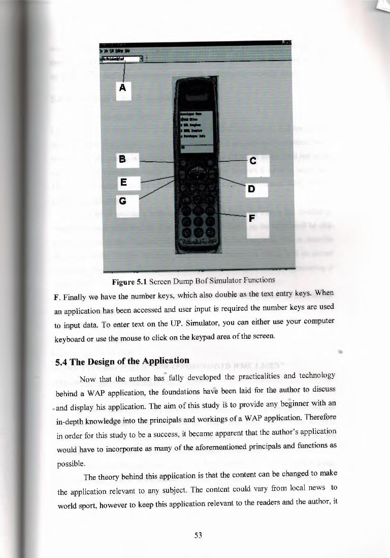
I'•.' ;!W'l'ffl'l''.''L'l'i'i'i'.'''' •.l'l''i·i'-',''. < •• ",'''
B
E
G
Figure 5.1 Screen Dump Bof Simulator Functions
F. Finally we have the number keys, which also double as the text entry keys. When
an application has been accessed and user input is required the number keys are used
to input data. To enter text on the UP. Simulator, you can either use your computer
keyboard or use the mouse to click on the keypad area of the screen.
•5.4 The Design of the Application
•.Now that the author has fully developed the practicalities and technology
behind a WAP application, the foundations have been laid for the author to discuss
.,,and display his application. The aim of this study is to provide any beginner with an
in-depth knowledge into the principals and workings of a WAP application. Therefore
in order for this study to be a success, it became apparent that the author's application
would have to incorporate as many of the aforementioned principals and functions as
possible.The theory behind this application is that the content can be changed to make
the application relevant to any subject. The content could vary from local news to
world sport, however to keep this application relevant to the readers and the author, it
53

was decided to design an application for the students at the University of Ulster. In
theory this application allows people to log on to the universities news site and read
up to date news that could interest and assist them for the fore coming period.
5.5 Developing a WAP Application
So how do we get started?Once you have obtained a knowledge and feel confidant using WML, it is time to start
designing your application. To begin one must open a new notepad document; this is
where the WML coding is saved in the same way that HTML is saved. And just in the
same way that in order to design a web page on the Internet it must be saved as a
HTML file, in order to design a WAP application it must be saved as a WML file e.g.
file://a:/example.wml.In order to provide a well-structured methodology, the author has decided to
breakdown the application into smaller programs. By doing so the author will be able
to show the individual functions of his application as well as being able to describe
the format of the Wireless Mark-up Language. Ultimately the coding will be pieced
together to display the author's new WAP application.5.6 How to Start Structuring A
WMLFile Before one can get started, one must realise that WAP Forum 1 to mention the
largest governs a standard for WAP.All WML files have to begin in a similar fashion; this is an example of how an
application may begin: -
<wml version= "1.0"?> <! DOCTYPE wml PUBLIC "-1/WAPFORUMIIDTD WML 1.11/EN"
"'http://www.wapforum.org!DTD!wml 1. 1.xml>
• These lines are necessary so that the version of WML can be established and
confirmed by the browsers. WML is an XML language and requires a DTD
(Documentation Type Declaration). If you don't use a DTD the browser will not
recognise it as all the WAP browsers look for the DTD declaration.
- As mentioned in the previous chapter, WML is very similar to HTML and is a tag
based language. Tags in WML are defined by an open tag< ...> and a close tag</ ... >.
- A WML file then starts with the tag <wml> and ends with </wml>.
54
ı:
•

Content within the WML file is encapsulated by the cards defined by the
tags<card> and </card>. Text should also be encapsulated with in <p> and <Ip> tags.
- WML also offers various tags that allow you to specify the font, size and layout of
text.- Furthermore the designer has the capabilities to maintain whatever format he/she
requires using tags such as, line break and alignment.And finally, there can be many cards within a WML file. This is called a
"deck" of cards. Consideration must be given to the quantity of information
supplied in the WML file. More content means longer download times and if
the user is unlikely to use all the cards within a deck it is wasting bandwidth
and time.
5.7 Creating a Static Title WML FileNow that all the key principals have been discussed, it is time to start
displaying the author's application. This is a static WML file that is used by the
author as a title page, and can be viewed in figure 4 below.
<? Xml version=! 1 .O'"?><! DOCTYPE WML PUBLIC "-//WAPFORUM//DTD WML 1.1//EN"
"http://www.wao.forum.org/DTD/wml_l. l.xml>
<BR>
ıı,ı.,
<wml>
<Card>
<p>Wireless Application Protocol
""
</BR>AUTHOR: DAMIEN MC MULLAN
<Ip>
</card>
</wml>
•
•
1 http://www.wapforum.com
55

Go ~/h:Jttlel:~lbct
:rı
Figure 5.2 Screen Dump of a Static Title Page
5.8.0 A Card By Card Analysis of the Author Application
The ideology behind the author's application is that any student with a
wireless device can retrieve information about the university and read up to the
moment news. The concept behind the application could be customised to bring the
user any type of information from world news to local sport.Once the user accesses the a!;lthor's application a title page is displayed, see
figure 5 below, this simply tells the user the topic of content located at this site.
••
56

;;ımıMIF:1?11 IIH:ih&ft
Figure 5.3 Screen Dump of Student Service Application
However, in order to make this application easier for the user a timer has been
put into place. The timer means that the title page is only displayed for an adequate
period of time, so as the user knows what information he/she is about to read. After a
couple of seconds the title page will automatically be replaced by card two, which
displays a series of topics and links which are available for the user to access.
<Card id="main" on timer="#c l ">
<Timer value="40"/>•<p><b><I>UNIVERSITY NEWS</I></b></br>
UP TO DATE UNIVERSITY OF ULSTER NEWS.
<Ip>
</card>
51

I !J~tıeıi~ UP.Simul.ıtor l!IQ £1[ıle lnlo Edit ~eıto_ı, tM>
Go !nıe:/ıh:/univeııity1.wrı-ıl ..:J
Figure 5.4 Screen Dump of Links
Now that the user has reached this stage in the application, he/she must know
decide their desired destination and begin to use the function keys and navigate for
them-selves, visual evidence of the links in provided in figure 6 above. Due to the fact
that there is a limited display on the UP Simulator, not all the links are visible on the
screen. The user must now scroll down using the arrow key to read all the options that
are available. .•A WML file is referred to as deck, made up of one or more cards of
+ ~
information; navigation between these cards is by hypertext links. The anchor tag
specifies the url when a link is selected, and the href part of the anchor tag specifies
the url to follow. The following example of coding not only shows how navigation
between cards works, but also how, it is programmed so that the user must accept a
link in order to view it. So if the user wants to view the content stored on card 4,
he/she must scroll down the links until the arrow is aligned with that link on the
simulator, this link must them be accepted by the user on the simulator.
58

<Card id="cl ">
<p><B> TIDS WEEKS UNIVERSITY NEWS</b>
<Do type=l'accept'' label=t'go">
<Go href="#c2"
/>
</do>
</p><p><a href="#c2">Kevin Curran's classes cancelled</a><br/></p>
<p><a href--"#c3">Library closes on Thursday</a><br/></p>
<p><a href="#c4">Soccer team reaches All-Ireland fınals</a><br/></p>
<p><a href--"#cS">End of term disco</a>-<br/></p>
</card>
l!.
••
~Micnd\ılad· .. 11•--ıı ~~""!'!.'!' .Uf' ....,
Figure 5.5 Screen Dump of Student Service Card Content.
The final function that is offered by the author to enable easy navigation is the
back function. This allows the user to return back to card 1 where the links are
59

displayed. This means that the user can pick and choose which information he/she
accesses and in which order. It was extremely necessary for the author to include this
function as the home button on the simulator is of no use in this application, as it is set
to the phone.com homepage by default.Now that the author has discussed the systems requirements, and provided a
detailed analysis into the actual workings of the application, the final-step before we
conclude this study is to test and evaluate the final application. This evaluation is
located in the following and penultimate chapter.
•..
60

6. TESTING AND EVALUATIONAs With all applications, we cannot be sure that a system is complete or error
free without full testing being carried out throughout its lifecycle and also on
completion of the product. Now that the application is complete, it must be tested to
make sure it is free from errors. This chapter explains how the author tested the
application to make sure that it achieved the requirements that are laid down at the
design stage of any application includingusabilityand performance.
For large applications there can be up to five different stages of testing
including, unit testing, module testing, and sub-system is testing, system testing and
acceptance testing. However when designing a WAP application, the majority of the
testing can be carried out as the application is being developed. Unit testing is the most
basic level of testing, which involves testing each component individually.Due to the
fact that you can view your application as you develop it on the simulator, it makes it
easy for the author to identify any errors at an early stage. Furthermore, just in the same
way that an error in java language is displayed to the author before a program will run,
the same process takes place in WML. If there is a error in the WML coding then the
application will not run on the simulator and it is possible for you to view your errors in
a MS-DOS window. At this stage the author can load and test each card on the
simulator, this means that any errors are detected at the earliest possible stage, and by
doing so causing less re-work.
During the next stage of testing the author can finally see whether or not the
application works as a whole. The system is now tested in full to see if all of the""
features do exactly what they are meant to do. The author must make sure that the links
work and take you to the correct"destination, that both the timer function and the back
functions are operational, and that the display rand format is exactly what the author
• wishes. As this application is not being sent live across the network, the- author is unable
to complete the final stage of testing, which would involve testing the product in the
market place.
6.1 EvaluationThis chapter will contain a summary of the overall application that has been
developed. It will discuss how successful the product is in achieving its aims put
forward in previous chapters. Furthermore it will also offer amendments, which could
61

be made to create a superior application. It is only after completing such a study that
one can step back and see what improvements are necessary.
From the outset, this thesis was an extreme challenge taken on by the author.
WAP is a new concept within the field of computers and mobile networks, and so very
little work has been conducted thus far. With many other subject areas, there is an
abundance of academic teachings and documentation; this was the first problem the
author had to overcome. Considering the fact that the author had absolutely no
experience prior to this study in this field, he had to firstly educate himself in all the
technologies and practicalities within WAP not to mention trying to get a grasp of a new
programming language.
When trying to develop an application for a deadline, one must adapt techniques
associated with project management. Equal time and resources had to be allocated to
each chapter. This was achieved by setting individual deadlines for each stage of
development.
6.1.1 Possible Enhancements
Now that the application is completed the author definitely feels that there are
improvements to be made, however this statement, should by no means, take away from
what the author has achieved. Throughout this study a vast wealth of knowledge into
wireless applications was obtained. It's in hindsight only, that the author can really
fathom the possibilities that await Wireless Application Protocols. With a greater time
allowance the author would be able to gather a better concept into WML Scripting, once
fluent in this dynamic language, to coin a phrase ''the world is your oyster".
However one must acknowledge that all the functional and non-functional
requirements and objectives discussed in the earlier chapters of this study have all been
uccessfullycompleted by the finalapplication. • •
6.1.2 Success Of The Application
The aim of this application was to deign and implement a dynamic student
service that could be accessed, by those who use WAP compatible wireless devices,
such as mobile phones. Anyone who has one of these devices can obtain up-to-the
moment news about the university. They can obtain useful university information at the
click of a button on their mobile phone. This information can vary from library closures
62

to fourth-coming exam timetables. Not only does the final application achieve all its
primary objectives, but it also conforms to all design guidelines, providing the users
with an attractive and easy to use interface.
•
•• •
•
63
CONCLUSION
In conducting this project, it is my wishes to have developed a wireless network
a WAP application, which could be customised to offer any content, at the click of a
button, to any WAP compatible wireless device. But it is also his wish to have also
developed an academic documentation that will educate any novice into the complex
workings of a WAP application. By reading this study it is hoped that any would-be
developer, May feel confident enough to precede and develop his/her own WAP
application.I developed this document, by breaking it into six important sections, and by
placing an equal amount of time and effort on each topic: -
1. Chapter-includea definition of wireless networks and its connections
2. Chapter- The architecture provides customers with a logical migration path to IP
based networking for achieving peer-to-peer and non-hierarchical communication while
maintaining interpretability with the existing infrastructure. This architecture permits
the partition of customer and the LAN network, enabling network managers the
flexibility for deploying end-customer services and applications independent of wireless
switch manufacturers. The Wireless architecture will provide the framework for
innovative technology enhancements. It's important to look at the interoperability
between different wireless technologies and the interfaces with one another. Wireless
manufacturers are adopting standards and conflicts could result from the use of different
standards in equipment in the same area. The current use of cell phones is different from
that of a WLAN; phones have higher power and lower bandwidth equipment than a
WLAN. The WLAN has a limited range, but it can be used as an extension of a wired..LAN. Those two can co-exist on the same network. As far as multiple standards go,• •there is IEEE 802.lla, which specifies 25mb/s at 5ghz and IEEE 802.llb, which
specifies llmb at 2.4ghz, and Home RF, which is at lmb/s and could be raised
to 1 Omb/s. It is not clear which standard will be adopted in the WLAN market, but once
one is developed, prices will fall as chipmakers develop specific ICs around the
standards, and the FCC may open a spectrum bandwidth and faster equipment, for
WLAN manufactures per cost, Today, the WLAN has redefined what it means to be
connected. It has stretched the limits of the LAN. It makes an infrastructure as dynamic
64

as it needs to be. It's only just beginning; the IEEE standard is less than three years old,
with the high speed IEEE 802.11b yet to reach its first birthday. With standard and
interoperable WLAN products, LAN can reach scales unimaginable with a wired
infrastructure. They can make high-speed interconnections for a fraction of the cost of
traditional wide area technologies. In a WLAN world, customers should be able to roam
not just within a campus but within a city, while maintaining a high speed link to
extranets, intranets, and the Internet itself The future of WLAN is imminent (OCBN
2001).3. Chapter - included a definition of the Wireless Application Protocol. A detailed
sub-section, including what the author was actually going to design, then followed this.
Once this was established a literary review was offered providing the concepts of others
who work in the field of wireless networks, namely the WAP forum.
4. Chapter - before one can discuss the methodology, the author felt that it was
necessary to firstly provide an in-depth analysis of the WAP architecture. This included
describing exactly how an application works across the network; features such as
servers, clients and gateways were all discussed. This chapter then shows how WAP
content is displayed and gives a brief insight into both the Wireless Mark-up and
Scripting languages.5. Chapter - contains the most important topics in this study, the methodology.
Firstly, the author discusses how to develop a simple application and then continues to
discuss the final product. Also in this section, are detailed instructions on how to use the
UP Platform and UP Simulator? The closing stages of this chapter analysis the actual
design and coding of the author's application, this is also supported using visual aides
such as screen dumps.6. Chapter - Comprises of the implementation, testing and evaluation of the final
application. Testing is discussed with regards to the UP. Simulator and how the.. developer can check for errors as the application are being developed. The evaluation
section offers possible enhancements that the author may consider, as well as discussing
how successful the application was in achieving its objectivesAfter developing and analysing a WAP application, there are many questions that still
remain in the author's mind. Without doubt, the ability to communicate with the web
immediately, wherever you are, has definitely sent those interested in the mobile
industry into a spin. But is this excitement premature?
65
Concluding this investigation, the author has come to realise that WAP has
two major flaws. It can be awkward and slow to use, and at present there is little really
useful information in WAP format. Even though the connection time may only be about
I O seconds, if used on a regular basis this is long enough to cause the user to become
distracted. Furthermore if you don't get anything useful at the end of it all, then the
whole idea may soon turn users off.
Taking these drawbacks into consideration, WAP needs to start making
serious advancements otherwise it may be swallowed by the next, even better
technology. The General Packet Radio System (GPRS) will bring the entire Internet to
mobile computers at a great speed. The GPRS will be much faster and much cheaper
than present cellular data. For many people such as Neil Bent, managing director at
"one to one", they believe that WAP is doomed. "WAP is a stepping stone- GPRS has
the potential to make WAP outdated very quickly. GPRS will cannibalise the market for
WAP because it will make surfing the real Internet possible, in full colour and with
graphics, sounds and animations we have come to expect".
(Source: Financial Times, March 151\ Alan Cane).
At first, the need to use a computer to access GPRS services will limit its
appeal to users, but soon phones that look more like a palm top computer will appear.
Users will be able to hold them in the palm of their hand and use an ear-piece just as
many do with the ordinary mobile phone today.
However it's the author's opinion that WAP will not just fade away, even if
it does not prove to be one of the major innovations of the twenty first century. There
will always be a certain percentage of the population that will want the convenience of
being able to obtain certain pieces of info and conduct certain tasks, from a pocket
device. The greatest obstacle that WAP faces is whether or not the market accepts the
concept. Will the consumer, with expectations built up for traditional web surfing,•accept the limited capabilities of WAP applications? And secondly, will the
advancements in technologies prove to be sufficient in order to keep the client
interested. Obviously, there are unanswered questions and uncertainties with regards to
WAP, however only time will answer these questions and iron out the problems. So
even if WAP technologies do not dominate the market in a way that it has the potential
to do, it will undoubtedly survive and continue to grow.
66

REFERENCES
[1]. S. Mann. Programming applications with the wireless application protocol, the
complete developers guide.
[2]. J. Wiley and son, 1999.
[3]. J. Wiley. Official wireless application protocol: The complete standard with
searchable CD-ROM. 1999.
[4]. W. Webb the complete wireless communications professional.
[5]. Attach house mobile communication series. 1999.
[6]. Financial Times, March ıs", 2000.
[7]. Mobile choice, (magazine article).Future connections, 1999.
[8]. what cell phone, (magazine article). Mobile data today, 1999.
••
67
WEB REFERENCES
[1]. A vital resource for WAP is the WAP Forum home page at
http://www.wapforum.com (WAP forum is the official coalition between all parties
committed to WAP. Its home page provides much of the necessary literature as well as
links to relevant sites, that any new WAP developer will require. Some of these sites are
listed below).[2]. Wireless mark up language specification.
http://www.wapforum.org/[3]. Wireless application protocol architecture specification
http://www.wapforum.org/
[4]. Goals of WAPhttp://www.wapforum.org/who/index.htm
[5]. WAP Gateway.http://www.apion-tss.com/CM!Products/wap.html
[6]. Official wireless application protocol.
http://www.wiley.com/compbooks/catalog/32755-7.htm
[7]. Homepage. (A second vital resource, which offers many important links)
http://www.phone.com
[8]. Developer's guide.
http://www.phone.com/developers/index.html
[9]. WAP overviewhttp://www.phone.com/industry/wap.html
[10].UP.SDK,Gettingl lstartedkit.2000
http://updev.phone.com/dev/ts/beta/docs/getstart/preface3.html
(1 l]. Fast and wireless, revolution is in the air. •
htU,://www.sonera.com "[12]. Homepage. (Third major resource for vital links)
•
•
http://www.nokia.com
(13]. the technologyhttp://www.nokia.com/corporate/wap/gateway case4.htrnl
[14]. what is WAP?
http://www.mobilewap.com/whatiswap.htm
[15]. Wireless http://www.whatis.com/wireless.htm
68
[16]. The Internet in your palın
http://www.cera2.com/smart/wap.htm
[ 1 7]. what is happening?
http://www.wapoutlook.com
[18]. Wireless pages
http://wapaw.com/
[19]. Search engine
http://www.wapwarp
[20]. WAP today
http://www.wap,more.com
[21]. Related Links
Apple Airport
http://www.apple.com/airport/
[22]. Security of the WEP algorithm
http://www.isaac.cs.berkeley.edu/isaac/wep-faq.html
[23]. Apple Airport base stations can be upgraded to 128-bit RC4
http://www.msrl.com/airport-gold/ -
[24]. Airport configuration tools
http://edge.mcs.drexel.edu/GICL/people/sevy/airport/
[25]. Karl Net Configuration
http://www.karlbridge.com/download/configsetup.exe
[26]. Dealing with Public Ethernet Jacks - Switches, Gateways, and Authentication
http://www.ualberta.ca/~beck/lisa99.html
[27]. Wireless Network Securityhttp://www.securityportal.com/researqh/research.wirelessnetwork.html
[28]. Wireless Security (by my boss Jim Reeves) •
•
http://www.nwfusion.com/newsletters/sec/1220secl .html ••[29]. Hackers poised to land at wireless Airport
http://www.zdnet.com/zdnn/stories/news/0,4586,2681947.00.html?chkpt=zdhpnews
69

APPENDIXES
APPENDIX A
DTD Document Type Definition, definition of a language built on XML or SGML.
GSM Global System for Mobile Communications.
HTML Hyper Text Mark-up Language, document definition language of WWW.
HTTP Hyper Text Transfer Protocol, transfer protocol of WWW
SGML Standardised General Mark-up Language, general mark-up languages that canbe adapted to different applications like IITML.
SSL Secure Sockets Layer, security protocol now known as TLS.
TLS Transport Layer security, security protocol formerly known as SSL.
URL l.'r-iform Resource Locator.
WAE Wireless Application Environment, execution environment for WAPapplications.
WAP Wireless Application Protocol, a set of protocols and standards for wirelessapplications.
WDP Wireless Data gram Protocol, the transport protocol of WAP.
WSP Wireless Session Protocol, the session protocol of WAP.
WTA Wireless Telephony Application, application programmings interface forcontrolling telephony features of the device.
WTLS Wireless Transport Layer Security, the security protocol of WAP.
·WTP Wireless Transaction Protocol, the transaction Protocol of WAP.
WWW World Wide Web.
•XML Extendable Mark-up Language, a subset of SGML.
70
APPENDIXB
DEFINITIONSAUTHOR - an author is a person or program that writes or generates WML, or other
content.
CARD - a single WML unit of navigation and user interface.
CLIENT - a device that initiates a request for connection with a server.
CLIENT DEVICE - a device providing the user with the user agent capabilities,
including the ability to request and receive information.
CONTENT - subject matter stored or generated at an ongın server. Content ıs
typically displayed or interpreted by a user agent in response to a user request.
DECK - a collection of WML cards.
DEVICE - a network entity that is capable of sending and receiving packets of
information and has a unique device address. A device can act as a client or a server.
ORIGIN SERVER - the server on which a given resource resides or is to be created.
Often referred to as a web server or a HTTP server.
SERVER - a device that waits for connection requests from one or more clients .
..USER - a user is a person who interacts with a user agent to view, or otherwise use a
resource.
71