with 5800b display installation guide - air-weigh truck scale comlink, loadmaxx 1 125-0000-000 drill...
TRANSCRIPT
Self-Weighing Truck and Trailer Scales™
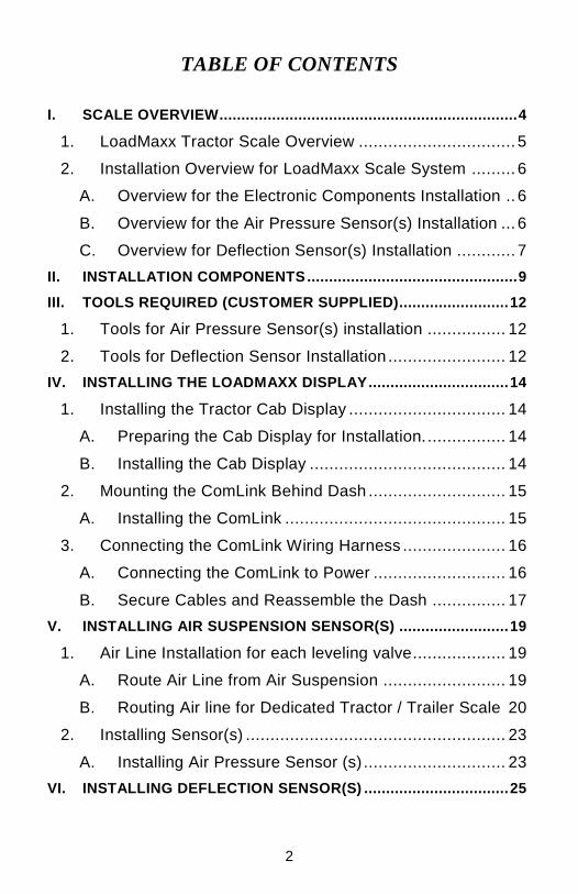
LoadMaxx™
Scale with 5800B Display
Installation Guide
for Trucks and Tractors
PN: 901-0126-000 R0
2
TABLE OF CONTENTS
I. SCALE OVERVIEW .................................................................... 4
1. LoadMaxx Tractor Scale Overview ................................ 5
2. Installation Overview for LoadMaxx Scale System ......... 6
A. Overview for the Electronic Components Installation .. 6
B. Overview for the Air Pressure Sensor(s) Installation ... 6
C. Overview for Deflection Sensor(s) Installation ............ 7
II. INSTALLATION COMPONENTS ................................................ 9
III. TOOLS REQUIRED (CUSTOMER SUPPLIED) ......................... 12
1. Tools for Air Pressure Sensor(s) installation ................ 12
2. Tools for Deflection Sensor Installation ........................ 12
IV. INSTALLING THE LOADMAXX DISPLAY ................................ 14
1. Installing the Tractor Cab Display ................................ 14
A. Preparing the Cab Display for Installation. ................ 14
B. Installing the Cab Display ........................................ 14
2. Mounting the ComLink Behind Dash ............................ 15
A. Installing the ComLink ............................................. 15
3. Connecting the ComLink Wiring Harness ..................... 16
A. Connecting the ComLink to Power ........................... 16
B. Secure Cables and Reassemble the Dash ............... 17
V. INSTALLING AIR SUSPENSION SENSOR(S) ......................... 19
1. Air Line Installation for each leveling valve................... 19
A. Route Air Line from Air Suspension ......................... 19
B. Routing Air line for Dedicated Tractor / Trailer Scale 20
2. Installing Sensor(s) ..................................................... 23
A. Installing Air Pressure Sensor (s) ............................. 23
VI. INSTALLING DEFLECTION SENSOR(S) ................................. 25

3
VII. FOR FURTHER INFORMATION ............................................... 29
LIMITED WARRANTY ...................................................................... 30
4
I. SCALE OVERVIEW
The Air-Weigh® Scale for trucks and tractors with AP (Air Pressure) drive suspension includes a dashboard-mounted display, a LoadMaxx™ ComLink, mounting cables, sensor cable(s), and sensor(s) with the necessary fittings and/or brackets for air and/or spring suspensions.
This Installation Guide (p/n: 901-0126-000) gives instructions for scale installations on vehicles having air drive suspensions, possibly in combination with air steer suspensions, dedicated tractor and trailer configurations, and/or spring steer suspension. For spring drive suspensions, it directs the user to other Air-Weigh documents. See Table 5. Kit Configuration Sensor Assignment for more detail on the various vehicle configurations.
Follow the installation procedures in this guide exactly for the most accurate weighing.
Table 1. Specifications
Display
Height: 1.85 inches (47.0 mm)
Width: 3.35 inches (85.1 mm)
Depth: 0.83 inches (21.1 mm) (excludes
adhesive)
Weight: 1.95 oz. (55 g)
Operating Temperature Range:
0 to 50C (32 to 122F)
Input voltage: Supplied by LoadMaxx ComLink
Tractor ComLink (5901)
Length: 2.84 inches (72.1 mm)
Width: 5.2 inches (132.1 mm)
Height: 1.12 inches (28.4 mm)
Operating Temperature Range:
- 40 to 85C (- 40 to 185F)
Input Voltage: 9.5V DC to 32V DC
Alarm Output Circuit Limit: 1.0 amps
Weigh Reading Accuracy
Axle with Air Sensor: ±300 lbs (140 kgs) per axle group
Axle with Deflection Sensor: ±2% maximum axle group weight
5
Following installation, you must calibrate the scale before you can use it to determine axle group and vehicle weight. For instructions on calibration, please consult p/n 901-0128-000, LoadMaxx with 5800B Display Calibration and
Operations Manual.
1. LoadMaxx Tractor Scale Overview
The LoadMaxx on-board scale converts tractor and trailer suspension loads to an accurate on-ground weight by comparing empty and loaded axle group weights with empty and loaded suspension pressures. Once calibrated, the scale displays accurate weights for any air suspension load.
The scale displays the actual on-ground weight of each axle group to within 300 pounds (140 kilograms) for air suspensions, or ±2% of maximum axle group weight for spring suspensions. An axle group is defined by the Height Control Valve(s) (HCV), or leveling valve(s), on the air suspension, or as the set of axles supporting a spring suspension. For instance, a tandem drive axle suspension typically has only one HCV. The two drive axles make up a single group and the displayed weight will be for the total tandem weight.
The LoadMaxx on-board scale can display up to eight axle groups on one tractor/trailer combination. Once the LoadMaxx is calibrated for weight, it is not necessary to recalibrate unless the suspension characteristics change.
Any tractor equipped with a LoadMaxx Tractor Scale will automatically display trailer weight data from Air-Weigh equipped trailers. No re-calibration or trailer ID entry is required. No special tractor/trailer connection is necessary because trailer weight data is transmitted over the vehicle’s existing 7-wire cable (J-560) without any interference. This is a true drop and hook application.
6
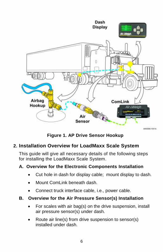
Figure 1. AP Drive Sensor Hookup
2. Installation Overview for LoadMaxx Scale System
This guide will give all necessary details of the following steps for installing the LoadMaxx Scale System.
A. Overview for the Electronic Components Installation
Cut hole in dash for display cable; mount display to dash.
Mount ComLink beneath dash.
Connect truck interface cable, i.e., power cable.
B. Overview for the Air Pressure Sensor(s) Installation
For scales with air bag(s) on the drive suspension, install air pressure sensor(s) under dash.
Route air line(s) from drive suspension to sensor(s) installed under dash.
7
For scales which calculate the weight at the steer axle from the drive axle suspension (configurations 5800, 5801, 5841, 5845, 5851, 5855, 5860), no steer axle sensor is needed.
For scales where the steer axle weight is intentionally not displayed (configurations 5803, 5816, 5840, 5844, 5850, 5854), no steer axle sensor is needed.
For scales with a steer axle with air suspension (configurations 5805, 5806, 5815, 5821, 5826, 5827, 5838, 5842, 5852, 5856), route air line(s) from steer axle suspension to sensor(s) installed under dash.
For scales which determine the weight at the lift axle (configurations 5833 – 5836 and 5838), refer to p/n 901-0117-000, Application Note, LoadMaxx, Installing and Calibrating the Lift Axle, for lift axle sensor installation instructions.
For Dedicated Tractor/Trailer Scales (configurations 5840 – 5860), route trailer suspension air line(s) to sensor(s) installed under dash.
C. Overview for Deflection Sensor(s) Installation
For scales that include steer axle deflection sensors (configurations 5807, 5808, 5814, 5817, 5822, 5823, 5831, 5833, 5834, 5835, 5836, 5843, 5846, 5853, 5857 or 5878), refer to p/n 901-0059-000, Steer Axle Deflection Sensor Kit Installation Guide, for installation instructions.
For scales that include dual drive axle deflection sensors on Hendrickson™ HaulMaxx or HN 462/463 suspensions (configurations 5810, 5814, 5818, 5824, 5828, 5829 or 5833), refer to p/n 901-0092-000, Drive Axle Dual Deflection Sensor Installation Guide.
For scales that include a single drive axle deflection sensor (configurations 5809, 5834, 5817 or 5846), contact Air-Weigh.
8
Ensure that each sensor’s electrical cable is connected to the correct LoadMaxx port. For a list of the correct port for each sensor, see Table
5, page 22.
9
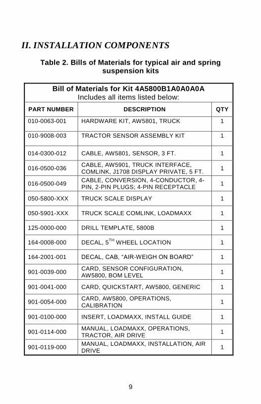
II. INSTALLATION COMPONENTS
Table 2. Bills of Materials for typical air and spring suspension kits
Bill of Materials for Kit 4A5800B1A0A0A0A Includes all items listed below:
PART NUMBER DESCRIPTION QTY
010-0063-001 HARDWARE KIT, AW5801, TRUCK 1
010-9008-003 TRACTOR SENSOR ASSEMBLY KIT 1
014-0300-012 CABLE, AW5801, SENSOR, 3 FT. 1
016-0500-036 CABLE, AW5901, TRUCK INTERFACE, COMLINK, J1708 DISPLAY PRIVATE, 5 FT.
1
016-0500-049 CABLE, CONVERSION, 4-CONDUCTOR, 4-PIN, 2-PIN PLUGS; 4-PIN RECEPTACLE
1
050-5800-XXX TRUCK SCALE DISPLAY 1
050-5901-XXX TRUCK SCALE COMLINK, LOADMAXX 1
125-0000-000 DRILL TEMPLATE, 5800B 1
164-0008-000 DECAL, 5TH
WHEEL LOCATION 1
164-2001-001 DECAL, CAB, “AIR-WEIGH ON BOARD” 1
901-0039-000 CARD, SENSOR CONFIGURATION, AW5800, BOM LEVEL
1
901-0041-000 CARD, QUICKSTART, AW5800, GENERIC 1
901-0054-000 CARD, AW5800, OPERATIONS, CALIBRATION
1
901-0100-000 INSERT, LOADMAXX, INSTALL GUIDE 1
901-0114-000 MANUAL, LOADMAXX, OPERATIONS, TRACTOR, AIR DRIVE
1
901-0119-000 MANUAL, LOADMAXX, INSTALLATION, AIR DRIVE
1
10
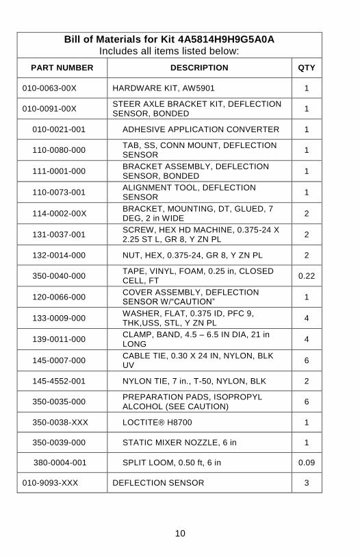
Bill of Materials for Kit 4A5814H9H9G5A0A Includes all items listed below:
PART NUMBER DESCRIPTION QTY
010-0063-00X HARDWARE KIT, AW5901 1
010-0091-00X STEER AXLE BRACKET KIT, DEFLECTION SENSOR, BONDED
1
010-0021-001 ADHESIVE APPLICATION CONVERTER 1
110-0080-000 TAB, SS, CONN MOUNT, DEFLECTION SENSOR
1
111-0001-000 BRACKET ASSEMBLY, DEFLECTION SENSOR, BONDED
1
110-0073-001 ALIGNMENT TOOL, DEFLECTION SENSOR
1
114-0002-00X BRACKET, MOUNTING, DT, GLUED, 7 DEG, 2 in WIDE
2
131-0037-001 SCREW, HEX HD MACHINE, 0.375-24 X 2.25 ST L, GR 8, Y ZN PL
2
132-0014-000 NUT, HEX, 0.375-24, GR 8, Y ZN PL 2
350-0040-000 TAPE, VINYL, FOAM, 0.25 in, CLOSED CELL, FT
0.22
120-0066-000 COVER ASSEMBLY, DEFLECTION SENSOR W/“CAUTION”
1
133-0009-000 WASHER, FLAT, 0.375 ID, PFC 9, THK,USS, STL, Y ZN PL
4
139-0011-000 CLAMP, BAND, 4.5 – 6.5 IN DIA, 21 in LONG
4
145-0007-000 CABLE TIE, 0.30 X 24 IN, NYLON, BLK UV
6
145-4552-001 NYLON TIE, 7 in., T-50, NYLON, BLK 2
350-0035-000 PREPARATION PADS, ISOPROPYL ALCOHOL (SEE CAUTION)
6
350-0038-XXX LOCTITE® H8700 1
350-0039-000 STATIC MIXER NOZZLE, 6 in 1
380-0004-001 SPLIT LOOM, 0.50 ft, 6 in 0.09
010-9093-XXX DEFLECTION SENSOR 3
11
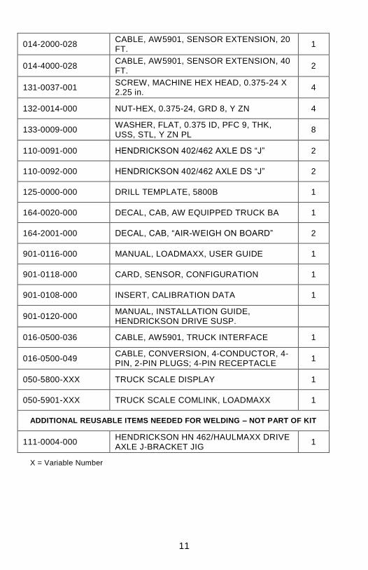
014-2000-028 CABLE, AW5901, SENSOR EXTENSION, 20 FT.
1
014-4000-028 CABLE, AW5901, SENSOR EXTENSION, 40 FT.
2
131-0037-001 SCREW, MACHINE HEX HEAD, 0.375-24 X 2.25 in.
4
132-0014-000 NUT-HEX, 0.375-24, GRD 8, Y ZN 4
133-0009-000 WASHER, FLAT, 0.375 ID, PFC 9, THK, USS, STL, Y ZN PL
8
110-0091-000 HENDRICKSON 402/462 AXLE DS “J” 2
110-0092-000 HENDRICKSON 402/462 AXLE DS “J” 2
125-0000-000 DRILL TEMPLATE, 5800B 1
164-0020-000 DECAL, CAB, AW EQUIPPED TRUCK BA 1
164-2001-000 DECAL, CAB, “AIR-WEIGH ON BOARD” 2
901-0116-000 MANUAL, LOADMAXX, USER GUIDE 1
901-0118-000 CARD, SENSOR, CONFIGURATION 1
901-0108-000 INSERT, CALIBRATION DATA 1
901-0120-000 MANUAL, INSTALLATION GUIDE, HENDRICKSON DRIVE SUSP.
016-0500-036 CABLE, AW5901, TRUCK INTERFACE 1
016-0500-049 CABLE, CONVERSION, 4-CONDUCTOR, 4-PIN, 2-PIN PLUGS; 4-PIN RECEPTACLE
1
050-5800-XXX TRUCK SCALE DISPLAY 1
050-5901-XXX TRUCK SCALE COMLINK, LOADMAXX 1
ADDITIONAL REUSABLE ITEMS NEEDED FOR WELDING – NOT PART OF KIT
111-0004-000 HENDRICKSON HN 462/HAULMAXX DRIVE AXLE J-BRACKET JIG
1
X = Variable Number
12
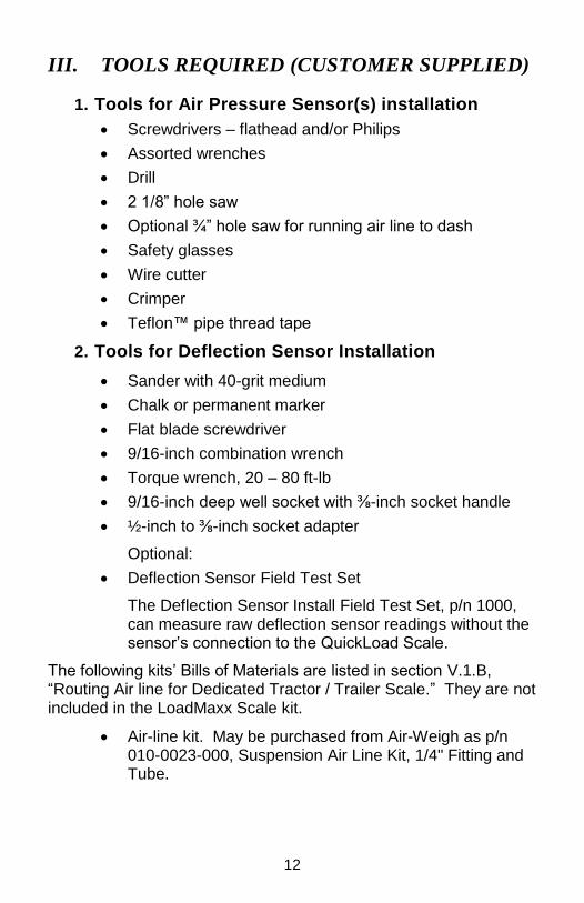
III. TOOLS REQUIRED (CUSTOMER SUPPLIED)
1. Tools for Air Pressure Sensor(s) installation
Screwdrivers – flathead and/or Philips
Assorted wrenches
Drill
2 1/8” hole saw
Optional ¾” hole saw for running air line to dash
Safety glasses
Wire cutter
Crimper
Teflon™ pipe thread tape
2. Tools for Deflection Sensor Installation
Sander with 40-grit medium
Chalk or permanent marker
Flat blade screwdriver
9/16-inch combination wrench
Torque wrench, 20 – 80 ft-lb
9/16-inch deep well socket with ⅜-inch socket handle
½-inch to ⅜-inch socket adapter
Optional:
Deflection Sensor Field Test Set
The Deflection Sensor Install Field Test Set, p/n 1000, can measure raw deflection sensor readings without the sensor’s connection to the QuickLoad Scale.
The following kits’ Bills of Materials are listed in section V.1.B, “Routing Air line for Dedicated Tractor / Trailer Scale.” They are not included in the LoadMaxx Scale kit.
Air-line kit. May be purchased from Air-Weigh as p/n 010-0023-000, Suspension Air Line Kit, 1/4" Fitting and Tube.

13
Trailer air disconnect kit. May be purchased from Air-Weigh as p/n 010-0028-002 Disconnect Kit, AW5800, Trailer-Direct, Quick Coupler, Fittings.
Two-trailer air disconnect kit. May be purchased from Air-Weigh as p/n 010-0029-002 Disconnect Kit, AW5800, Two-Trailers-Direct, Quick Couplers, Fittings.
14
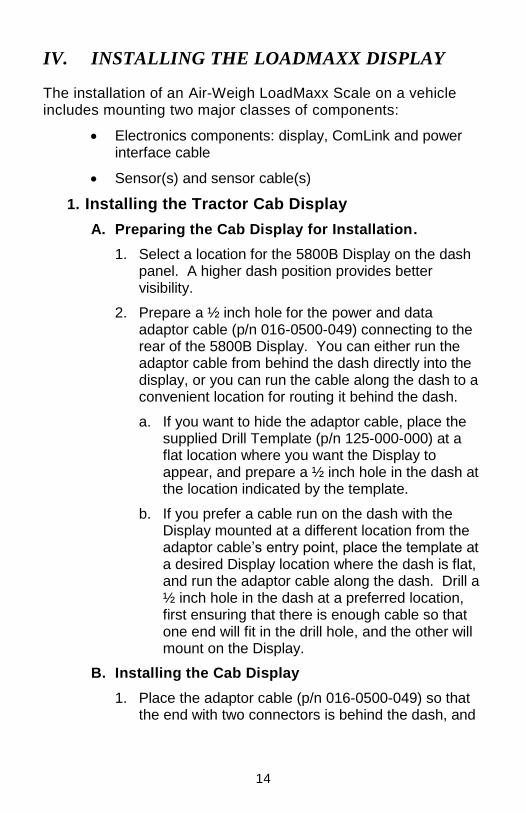
IV. INSTALLING THE LOADMAXX DISPLAY
The installation of an Air-Weigh LoadMaxx Scale on a vehicle includes mounting two major classes of components:
Electronics components: display, ComLink and power interface cable
Sensor(s) and sensor cable(s)
1. Installing the Tractor Cab Display
A. Preparing the Cab Display for Installation.
1. Select a location for the 5800B Display on the dash panel. A higher dash position provides better visibility.
2. Prepare a ½ inch hole for the power and data adaptor cable (p/n 016-0500-049) connecting to the rear of the 5800B Display. You can either run the adaptor cable from behind the dash directly into the display, or you can run the cable along the dash to a convenient location for routing it behind the dash.
a. If you want to hide the adaptor cable, place the supplied Drill Template (p/n 125-000-000) at a flat location where you want the Display to appear, and prepare a ½ inch hole in the dash at the location indicated by the template.
b. If you prefer a cable run on the dash with the Display mounted at a different location from the adaptor cable’s entry point, place the template at a desired Display location where the dash is flat, and run the adaptor cable along the dash. Drill a ½ inch hole in the dash at a preferred location, first ensuring that there is enough cable so that one end will fit in the drill hole, and the other will mount on the Display.
B. Installing the Cab Display
1. Place the adaptor cable (p/n 016-0500-049) so that the end with two connectors is behind the dash, and
15
the end with one connector comes through the ½ inch hole.
2. Mount the connector at the single-connector end of the adaptor cable (p/n 016-0500-049) to the Display’s connector port at its rear, threading the cable through the entry way at the Display’s underside.
3. Remove all dust, grease or debris from the flat location where you will mount the Display, using the supplied alcohol pad. Remove the red strips from the back of the Display, exposing the adhesive tape. Place the Display against the cleaned flat area and push it hard enough to ensure adhesion. For best results, push the Display into place using steady force, being careful not to crack the case.
2. Mounting the ComLink Behind Dash
A. Installing the ComLink
Select a location behind the dash for the LoadMaxx ComLink, ensuring there is adequate access to the scale and the electrical connections.
The LoadMaxx ComLink should be oriented with the connectors facing downward and installed by any of the following three methods, using the hardware provided.
1. Use wire ties through the holes in the ComLink mounting ears to secure it to any appropriate wire harness behind the dash.
- OR -
2. Find a flat location where the ComLink can be attached using the 2-sided adhesive tape already in position on the back of the ComLink. Remove all dust, grease or debris from the flat location, using the supplied alcohol pad. Remove one or both of the red strips from the back of the ComLink, exposing the adhesive tape. Place the ComLink against the cleaned flat area and push it hard enough to ensure adhesion. For best results, push the ComLink into place using steady force, being
16
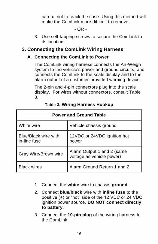
careful not to crack the case. Using this method will make the ComLink more difficult to remove.
- OR -
3. Use self-tapping screws to secure the ComLink to its location.
3. Connecting the ComLink Wiring Harness
A. Connecting the ComLink to Power
The ComLink wiring harness connects the Air-Weigh system to the vehicle’s power and ground circuits, and connects the ComLink to the scale display and to the alarm output of a customer-provided warning device.
The 2-pin and 4-pin connectors plug into the scale display. For wires without connectors, consult Table 3.
Table 3. Wiring Harness Hookup
Power and Ground Table
White wire Vehicle chassis ground
Blue/Black wire with in-line fuse
12VDC or 24VDC ignition hot power
Gray Wire/Brown wire Alarm Output 1 and 2 (same voltage as vehicle power)
Black wires Alarm Ground Return 1 and 2
1. Connect the white wire to chassis ground.
2. Connect blue/black wire with inline fuse to the positive (+) or “hot” side of the 12 VDC or 24 VDC ignition power source. DO NOT connect directly to battery.
3. Connect the 10-pin plug of the wiring harness to the ComLink.
17
4. Connect both the 2-pin and the 4-pin plugs of the wiring harness to the adaptor cable (p/n 016-0500-049) that is already connected to the Display.
5. When using an alarm, connect the alarm output wire and the ground return wire to the desired device (buzzer, horn, light, etc.). Ensure that any unused alarm wires are electrically insulated.
B. Secure Cables and Reassemble the Dash
1. Coil excess wires and harnesses and secure using nylon cable ties.
2. Tie wires and sensor assemblies to other secured harnesses, to prevent damage due to vibration.
3. Reassemble the dash assembly. Ensure all connections are tight.
4. Turn the ignition key ON and perform a final system check.
The scale will only display accurate weights after it has been completely calibrated to a certified platform scale, by entering empty and loaded axle weights into the Air-Weigh Scale. Enter empty weights only when the vehicle is empty! Enter loaded weights only when the vehicle is loaded!
See LoadMaxx Calibration and Operations Manual, p/n 901-0128-000, for complete instructions.
18
If the scale system includes the optional printer, the printer wiring is made up of three cables; see Printer Installation Instructions, p/n 901-0105-000, in your Printer Kit package.
One cable permanently connects to the Printer Port on the ComLink and to a connector hole in the dash. Another cable connects to the printer. The third cable joins these two together. The 2-part cable assembly between the printer and the dash is designed for easily disconnecting from the dash. Store the printer and its cables in a clean, dry place when not in use.
19
V. INSTALLING AIR SUSPENSION SENSOR(S)
1. Air Line Installation for each leveling valve
A. Route Air Line from Air Suspension
Follow the same instructions for air line and sensor installation for both drive and steer air suspensions. The parts in this section’s instructions are listed in Table 4.
If an Air Suspension Gauge for the suspension already exists in dash, skip to V.2, Installing Sensor(s). Otherwise, continue with this procedure.
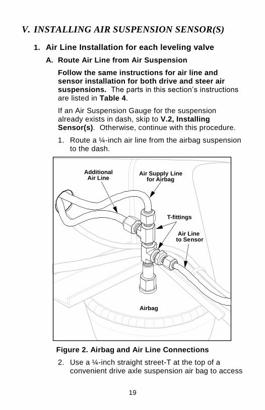
1. Route a ¼-inch air line from the airbag suspension to the dash.
Figure 2. Airbag and Air Line Connections
2. Use a ¼-inch straight street-T at the top of a convenient drive axle suspension air bag to access
Air Supply Linefor Airbag
T-fittings
Air Line �to Sensor
Additional�Air Line
Airbag
20
air pressure. If you choose to connect in the middle of an existing air line between two air bags, thoroughly remove any paint on the air line and wipe clean before cutting the air line.
3. Route the air line along with other air lines and cables into the dash. Loosely connect the air line to the other air lines and cable with cable ties to prevent it from being damaged.
B. Routing Air line for Dedicated Tractor / Trailer Scale
The parts in this section’s instructions are listed in Table 4. If Trailer Suspension gauge already exists in dash, skip to V.2, Installing Sensor(s).
Table 4. Air Line and Disconnect Kit BOMs
Bill of Materials for Suspension Air Line Kit, p/n 010-0023-000
PART NUMBER DESCRIPTION QTY
145-4552-001 NYLON TIE, 7", T-50, NYLON, BLK 25
150-4081-000 ¼ NPT STREET TEE, DOT, BRASS 1
150-4083-000 DOT COMPRESSION, ¼ NPT, MALE,BRASS 1
380-0046-000 40' X ¼” SAE J844 DOT TUBING 1
BOM for Trailer-Direct Disconnect Kit, p/n 010-0028-002
145-4552-001 NYLON TIE, 7", T-50, NYLON, BLK 25
150-4081-000 ¼ NPT STREET TEE, DOT, BRASS 1
150-4083-000 DOT COMPRESSION, ¼ NPT, MALE,BRASS 3
Avoid connecting on the air bag’s supply line.
21
150-4091-000 FITTING, BRASS, QUICK COUPLER, MALE 1
150-4092-000 FITTING, BRASS, ADAPTER PLUG,FEMALE 1
152-0001-000 BULKHEAD FITTING, 1/4" NPT 2
380-0050-000 100' X ¼” SAE J844 DOT TUBING 1
380-0053-000 AIR HOSE, COILED, 1/4" NPT X 2, 25’ 1
901-0052-000 INSERT, AW5800, TRAILER-DIRECT 1
BOM for Two-Trailer-Direct Disconnect Kit, p/n 010-0029-002
145-4552-001 NYLON TIE, 7", T-50, NYLON, BLK 50
150-4081-000 ¼ NPT STREET TEE, DOT, BRASS 2
150-4083-000 DOT COMPRESSION, ¼ NPT, MALE,BRASS 8
150-4091-000 FITTING, BRASS, QUICK COUPLER, MALE 3
150-4092-000 FITTING, BRASS, ADAPTER PLUG,FEMALE 3
152-0001-000 BULKHEAD FITTING, 1/4" NPT 6
380-0046-000 40' X ¼” SAE J844 DOT TUBING 1
380-0050-000 100' X ¼” SAE J844 DOT TUBING 2
380-0053-000 AIR HOSE, COILED, 1/4" NPT X 2, 25’ 3
901-0065-000 INSERT, AW5800, TWO-TRAILERS-DIRECT 1
1. Remove existing air line connection from one trailer air bag.
2. Install street-T (p/n: 150-4081-000) into air bag.
3. Install fitting (p/n: 150-4083-000) into side of street-T and connect to air line (p/n: 380-0050-000).
4. Reinstall original air line and fitting connector to top of street-T.
22
5. Run air line (p/n: 380-0050-000) to front of trailer. Secure with cable ties.
6. Drill hole for trailer bulkhead fitting at a point near where existing airlines attach to trailer.
7. Install bulkhead fitting (p/n: 152-0001-000).
8. Cut air line to length and connect to rear side of bulkhead fitting. Use remaining air line in step 13.
9. Attach female quick-disconnect coupling (p/n: 150-4092-000) to face of bulkhead fitting.
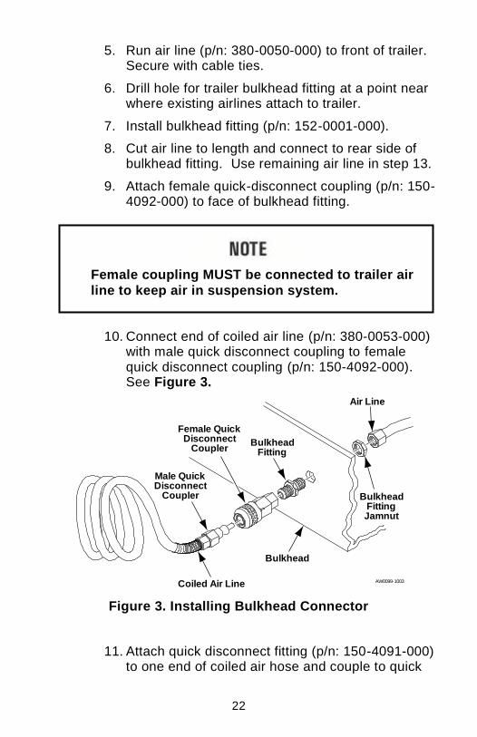
10. Connect end of coiled air line (p/n: 380-0053-000) with male quick disconnect coupling to female quick disconnect coupling (p/n: 150-4092-000). See Figure 3.
Figure 3. Installing Bulkhead Connector
11. Attach quick disconnect fitting (p/n: 150-4091-000) to one end of coiled air hose and couple to quick
Coiled Air Line
Female QuickDisconnect
Coupler
Male QuickDisconnect
Coupler
BulkheadFitting
BulkheadFittingJamnut
Air Line
Bulkhead
AW0099-1003
Female coupling MUST be connected to trailer air
line to keep air in suspension system.
23
disconnect fitting (p/n: 150-4092-000) on front bulkhead of trailer. See Figure 3.
12. Drill hole in tractor bulkhead near where existing air lines attach to the tractor and install bulkhead fitting (p/n: 152-0001-000).
13. Connect the other end of the coiled air line (p/n: 380-0053-000) to the face of the bulkhead fitting.
14. Install brass fitting (p/n: 150-4083-000) into rear of bulkhead fitting. Run air line (380-0050-000) from brass fitting to under dash, close to ComLink mounting location. Secure with wire ties.
15. Connect open end of air line, near ComLink, to push-on fitting on end of Air Pressure Sensor.
16. Connect electrical cable from opposite end of air pressure sensor to appropriate port on ComLink. See Table 5. Kit Configuration Sensor Assignment to determine the appropriate port for the sensor connector.
2. Installing Sensor(s)
A. Installing Air Pressure Sensor (s)
There are two methods of installing the sensor connections to the suspension air line(s) under the dash. See Figure 4. Connecting the Air Pressure Sensor
1. Insert a T-fitting into an existing suspension air gauge.
2. Terminate the air line into the nickel plated brass fitting supplied by Air-Weigh.
Avoid dropping the sensors. Dropping can cause the sensors to fail immediately or shorten their lifespan.
24
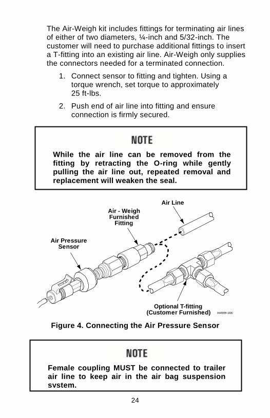
The Air-Weigh kit includes fittings for terminating air lines of either of two diameters, ¼-inch and 5/32-inch. The customer will need to purchase additional fittings to insert a T-fitting into an existing air line. Air-Weigh only supplies the connectors needed for a terminated connection.
1. Connect sensor to fitting and tighten. Using a torque wrench, set torque to approximately 25 ft-lbs.
2. Push end of air line into fitting and ensure connection is firmly secured.
Figure 4. Connecting the Air Pressure Sensor
Air - WeighFurnished
Fitting
Air PressureSensor
Air Line
Optional T-fitting(Customer Furnished) AW0099-1005
While the air line can be removed from the fitting by retracting the O-ring while gently pulling the air line out, repeated removal and replacement will weaken the seal.
Female coupling MUST be connected to trailer air line to keep air in the air bag suspension system.
25
For installation of the Hendrickson Walking Beam drive axle deflection sensor, refer to p/n 901-0092-000, Steer Axle Deflection Sensor Kit Installation Guide, which is included in kit 1392, for installation
instructions.
For installation of the Mack® Camelback drive axle deflection sensor, refer to p/n 901-0102-000, Installation Guide for Vocational Vehicles with Mack® Camelback Suspensions, for installation instructions.
For installation of the Volvo T-Ride drive axle deflection sensor, refer to p/n 901-0125-000, Manual, LoadMaxx Install on Volvo T-Ride, for
installation instructions.
VI. INSTALLING DEFLECTION SENSOR(S)
When installing kits with configurations 5807, 5808, 5843, 5846, 5853, 5857 or 5878, which include steer axle deflection sensors, refer to p/n 901-0059-000, Steer Axle Deflection Sensor Kit Installation Guide,
for installation instructions.
26
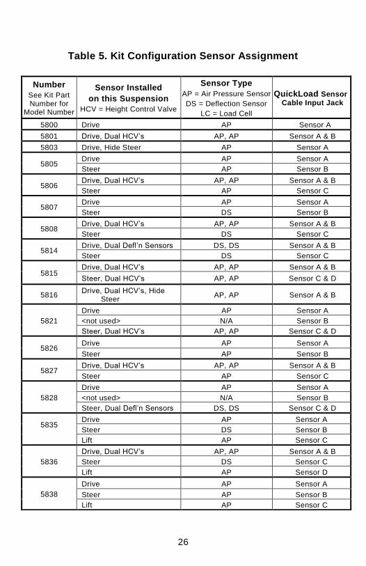
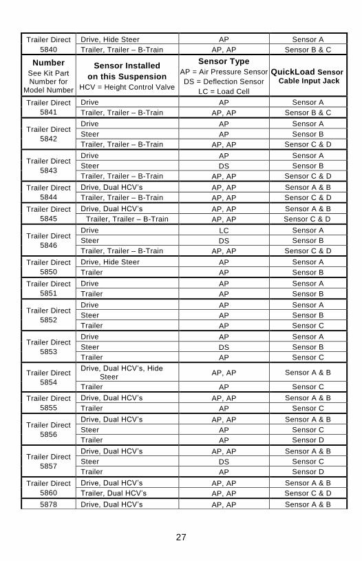
Table 5. Kit Configuration Sensor Assignment
Number
See Kit Part Number for
Model Number
Sensor Installed
on this Suspension
HCV = Height Control Valve
Sensor Type
AP = Air Pressure Sensor
DS = Deflection Sensor
LC = Load Cell
QuickLoad Sensor Cable Input Jack
5800 Drive AP Sensor A
5801 Drive, Dual HCV’s AP, AP Sensor A & B
5803 Drive, Hide Steer AP Sensor A
5805 Drive AP Sensor A
Steer AP Sensor B
5806 Drive, Dual HCV’s AP, AP Sensor A & B
Steer AP Sensor C
5807 Drive AP Sensor A
Steer DS Sensor B
5808 Drive, Dual HCV’s AP, AP Sensor A & B
Steer DS Sensor C
5814 Drive, Dual Defl’n Sensors DS, DS Sensor A & B
Steer DS Sensor C
5815 Drive, Dual HCV’s AP, AP Sensor A & B
Steer, Dual HCV’s AP, AP Sensor C & D
5816 Drive, Dual HCV’s, Hide
Steer AP, AP Sensor A & B
5821
Drive AP Sensor A
<not used> N/A Sensor B
Steer, Dual HCV’s AP, AP Sensor C & D
5826 Drive AP Sensor A
Steer AP Sensor B
5827 Drive, Dual HCV’s AP, AP Sensor A & B
Steer AP Sensor C
5828
Drive AP Sensor A
<not used> N/A Sensor B
Steer, Dual Defl’n Sensors DS, DS Sensor C & D
5835
Drive AP Sensor A
Steer DS Sensor B
Lift AP Sensor C
5836
Drive, Dual HCV’s AP, AP Sensor A & B
Steer DS Sensor C
Lift AP Sensor D
5838
Drive AP Sensor A
Steer AP Sensor B
Lift AP Sensor C
27
Trailer Direct
5840
Drive, Hide Steer AP Sensor A
Trailer, Trailer – B-Train AP, AP Sensor B & C
Number
See Kit Part Number for
Model Number
Sensor Installed
on this Suspension
HCV = Height Control Valve
Sensor Type
AP = Air Pressure Sensor
DS = Deflection Sensor
LC = Load Cell
QuickLoad Sensor
Cable Input Jack
Trailer Direct
5841
Drive AP Sensor A
Trailer, Trailer – B-Train AP, AP Sensor B & C
Trailer Direct
5842
Drive AP Sensor A
Steer AP Sensor B
Trailer, Trailer – B-Train AP, AP Sensor C & D
Trailer Direct
5843
Drive AP Sensor A
Steer DS Sensor B
Trailer, Trailer – B-Train AP, AP Sensor C & D
Trailer Direct
5844
Drive, Dual HCV’s AP, AP Sensor A & B
Trailer, Trailer – B-Train AP, AP Sensor C & D
Trailer Direct
5845
Drive, Dual HCV’s AP, AP Sensor A & B
Trailer, Trailer – B-Train AP, AP Sensor C & D
Trailer Direct
5846
Drive LC Sensor A
Steer DS Sensor B
Trailer, Trailer – B-Train AP, AP Sensor C & D
Trailer Direct
5850
Drive, Hide Steer AP Sensor A
Trailer AP Sensor B
Trailer Direct
5851
Drive AP Sensor A
Trailer AP Sensor B
Trailer Direct
5852
Drive AP Sensor A
Steer AP Sensor B
Trailer AP Sensor C
Trailer Direct
5853
Drive AP Sensor A
Steer DS Sensor B
Trailer AP Sensor C
Trailer Direct
5854
Drive, Dual HCV’s, Hide Steer
AP, AP Sensor A & B
Trailer AP Sensor C
Trailer Direct
5855
Drive, Dual HCV’s AP, AP Sensor A & B
Trailer AP Sensor C
Trailer Direct
5856
Drive, Dual HCV’s AP, AP Sensor A & B
Steer AP Sensor C
Trailer AP Sensor D
Trailer Direct
5857
Drive, Dual HCV’s AP, AP Sensor A & B
Steer DS Sensor C
Trailer AP Sensor D
Trailer Direct
5860
Drive, Dual HCV’s AP, AP Sensor A & B
Trailer, Dual HCV’s AP, AP Sensor C & D
5878 Drive, Dual HCV’s AP, AP Sensor A & B

28
No FSK Steer DS Sensor C
29
VII. FOR FURTHER INFORMATION
Included in the Scale Kit:
901-0039-000 – Card, Sensor Configuration, AW5800, BOM Level
901-0041-000 – Card, Quickstart, AW5800, Generic
901-0054-000 – Card, AW5800, Operations, Calibration
901-0114-000 – Manual, LoadMaxx, Operations, Tractor, Air Drive
Included in the Printer Kit:
901-0105-000 – Air-Weigh Date Time Printer Installation Instructions
Included in the Trailer-Direct or Two-Trailers-Direct Disconnect Kit:
901-0052-000 – Insert, AW5800, Trailer-Direct
901-0065-000 – Insert, AW5800, Two-Trailers-Direct
901-0100-000 – Insert, LoadMaxx, Install Guide
Available from Air-Weigh Support:
901-0059-000 – Steer Axle Deflection Sensor Kit Installation Guide
901-0077-000 – Operating Voltages and Current for 5800 Series Products
901-0092-000 – Manual, Defl Sensor, J Bracket Installation
901-0102-000 – Installation Guide for Vocational Vehicles with Mack® Camelback Suspensions
901-0117-000 – Application Note, LoadMaxx, Calibrating The Lift Axle
901-0125-000 – Manual, LoadMaxx Install on Volvo T-Ride
30
LIMITED WARRANTY
For product failures due to material or manufacturing defects, Air-Weigh will replace or repair all components for up to 3 years from shipment date to the end-user Air-Weigh customer. These three-year components include: Displays, ComLinks, Air Sensors, Power Cables, Air Sensor Assemblies, Air Sensor Harnesses, and all other associated external components. Air-Weigh assumes no responsibility for administering warranty claims directly with any third party end users. The responsibility of Air-Weigh under this warranty is limited to the repair, replacement, or credit of the defective part or assembly.
This warranty does not cover incidental or consequential damage to persons or property caused by use, abuse, misuse, or failure to comply with installation or operating instructions. This limited warranty does not apply to any product that has failed due to accident, abuse, alteration, installation not consistent with printed installation instructions, improper maintenance, improper operation, or as a result of system integration or installation not explicitly approved in writing by Air-Weigh.
Air-Weigh and its resellers shall have no responsibility or liability for damages if the purchaser or any other person alters the vehicle incorporating Air -Weigh products. This limited warranty shall not apply to any product that has been repaired or altered by anyone not employed by Air-Weigh or not operated in accordance with the manufacturer’s printed material delivered with this product.
Air-Weigh hereby expressly disclaims any and all implied warranties of any type, kind of nature whatsoever, particularly any implied warranty of merchantability or fitness for a particular purpose not expressly stated by Air -Weigh in its printed material delivered with its products.
Some states do not allow the exclusion or limitation of incidental or consequential damages. If such laws apply, the limitations or exclusions contained in the terms and conditions of this Warranty may not apply. This warranty gives you specific legal rights and you may also have other rights, which vary state to state.
May be covered by U.S. Patent Nos. 4832141, 5478974, 5780782, 7478001, Foreign Patent Nos. 623635, 1305191, 260494, 677998, 2122766, 625697
Copyright © 2004, 2006, 2007, 2008, 2009, 2010 by Hi-Tech Transport Electronics, Inc. All rights reserved. Air-Weigh®, ComLink™ and Hi-Tech Transport Electronics are trademarks or registered trademarks of Hi-Tech Transport Electronics, Incorporated. Other brand, product, or service names listed in this document are the trademarks or registered trademarks of their respective holders. Information contained in this literature was accurate at time of publication. Product changes may have been made after copyright dates that are not reflected.
31
PROCEDURE FOR WARRANTY CLAIMS
1. In the event Air-Weigh requests to examine product prior to disposition, OR for repairs or replacements, Air-Weigh requires a Return Material Authorization (RMA) number to be issued before the item is returned. Contact Customer Support Department at (888) 459-3247 for an RMA number. Please reference this RMA number in all correspondence.
2. Claimed items shall be shipped freight pre-paid to: Air-Weigh, Customer Support Department, 1730 Willow Creek Circle, Eugene, Oregon 97402, USA. The Air-Weigh RMA number shall appear on the outside of the return packaging.
3. Air-Weigh shall examine returned material within 30 days after receipt, or sooner if mutually agreed upon. If Air-Weigh determines that the part or assembly was defective in material or workmanship and within the warranty period, Air-Weigh will repair or replace the part or assembly and return freight pre-paid. In the event Air-Weigh determines that the part or assembly cannot be repaired or replaced and is within the warranty period, a credit not to exceed the purchase price will be issued to the Air-Weigh customer.
4. Air-Weigh Accounting will process a credit memo and notify the Air-Weigh customer by email or fax. The Air-Weigh customer will process a corresponding debit memo and notify Air-Weigh Accounting.
5. If the part or assembly received by Air-Weigh does not meet the requirements of the warranty program set forth above, at the Air-Weigh customer’s request the part or assembly will either be discarded, returned freight collect, or repaired or replaced at the Air-Weigh customer’s expense and returned freight collect.

32
1730 Willow Creek Circle • Eugene, Oregon 97402-9152 USA
P.O.Box 24308 • Eugene, Oregon 97402-0437 USA
Telephone (541) 343-7884 • Order Desk (888) 459-3444 Customer Support (888) 459-3247 • FAX (541) 431-3121 Hours of Operation: Mon-Fri, 7am – 5pm, Pacific Time
www.Air-Weigh.com