with the e4od or manual transmission wiring instructions · with the e4od or manual transmission...
TRANSCRIPT

Page #1
TELORVEK EFI1993-95 Ford Truck & Lightning
5.0, 5.8 Fuel InjectionSystem (ML-93)
With the E4OD or Manual Transmission
WIRING INSTRUCTIONS
Thank you for purchasing the absolute finest of wiring kits for the Ford Motor Co. 5.0 truck and 5.8Lighting truck fuel injection engine. We have taken considerable time to work out the circuitry so thatyou, the customer will understand at least some of what this is all about. We ask that you follow ourinstructions closely. We recommend using a high pressure in tank fuel (45 PBS min.) pump. Custominstallations are available from Tanks Inc. (phone #320-558-6882) and Rock Valley (phone #800-344-
1934).
Should you eliminate a sensor, your injection system will not work at its peak and will probably be insome variation of back up mode. There are many factors that will help you get a trouble free start up that
you must consider.
NOTE!! FORD diagnostic procedures are very detailed, lengthy and impossible to
cover in this set of instructions. Purchasing the FORD ENGINE/
EMISSIONS DIAGNOSIS shop manual will help you learn about the engine
you installed and guide you through the correct diagnostic procedures
Ford recommends. This book is available through your local Ford dealer or
Helm Inc. Helm is the distributor for the shop manuals for General Motors
and Ford Motor Company. Helm can be contacted at 800-782-4356 or on
their web site www.helminc.com
WARNING!
After the kit installation is complete and it is necessary to diagnose
a starting or drive ability problem, follow the procedures
recommended in the shop manual. All voltage tests must be
preformed using a HIGH impedance, digital voltmeter. DO NOT use
a test light on this system! DAMAGE WILL BE DONE to the engine
computer if a test light is used on this system.
Page #2
Ron Francis Wiring fuel injection wire harnesses are “ALL” designed to follow the
electronic circuitry of the vehicle your engine was removed from! Following this
simple procedure allows our fuel injection harness customers to have their vehicles
diagnosed by “ANY” FORD dealer or reputable repair facility familiar with diagnosing
fuel injection electronic systems.
Ron Francis Wiring does not re-engineer electronic circuitry that a vehicle
manufacturer has spent millions of dollars on testing and designing. Our goal is to
allow an “easy”, “neat”, “pain free” installation through quality installation
instructions and a state of the art wiring kit.
If your vehicle experiences starting or runability problems, 99% of the time
it is some sort of mechanical, NOT A WIRING PROBLEM. Fuel injection engines still
run similar to carbureted engines, the difference being that the engine computer
receives “inputs” from various sensors throughout the engine. The computer then
uses this information to calibrate fuel delivery and engine timing.
Diagnosing a NO SPARK situation is the same on a computer controlled fuel
injection engine as it is on a carbureted engine. Spark control, even though it may
be done slightly different depending on engine year and make, is still essentially the
same. A rotor is turned allowing spark to be provided to the plugs, the same as in a
carbureted engine.
Thank you for purchasing our products!

Page #3
STARTING INSTALLATION
Since there are so many individual circuits to complete, we recommend that you connect them in theorder that we prescribe. Disconnect the battery before starting and do not reconnect until instructed.
There will be many connections to the TELORVEK panel so plan the location of the panel in an area withroom to work. We suggest mounting the panel in an assessable location, in the trunk, under the seat orunder the dash are good. In order to allow for the proper spacing between the computer and the
Telorvek panel, plug the connector into the computer (ECM) and mount the panel and computer. For
safety, disconnect the ECM connector until finished the installation. A poor installation
will result in a poor running car. The number referred to from this point on will be the
location on one of the terminal blocks located on the TELORVEK panel.
Always put the first terminal under a screw with the fat wire side down as in the drawing.Install any second terminals just the opposite as this will allow the screw to hold squarelyand tight. The insulation from one terminal should not interfere with the one next to it.
Use a crimping tool that is designed for insulated terminals. If the tool punctures theinsulation (plastic) or damages it in any way, you are using the wrong tool. The proper tool will only"flatten" the plastic and if the handles are squeezed completely, the proper crimp has been made. Getin the habit of test pulling at each terminal as you crimp it to the wire.
After all wires are connected to the engine, wire tie them together or use 3/4 inch Zip loom to protectthem. This can be done before any connections are made to the panel. Since all wires are marked,running the entire group to the panel at one time is fine. Some terminals on the panel may not be used!
*******
Important! We have supplied three sizes of terminals for your use on the panels itself. The Yellow isused on the 10-12 gauge wire, Blue is used on 14-16 gauge wire and Red is used for the bulk of thesmaller wires. Each individual bag instructions will be marked as to when to use the yellow or blue,terminals, all other wires will use the red terminals.
L NOTE 7You will be moving around to different terminals on the TELORVEK
panel to make connections. For this reason extra care is needed
when making all connections to the panel.

Page #4
Bag #20. INJECTORS: The injector wiring is made up in a harness with two branches, one branchfor the left side (drivers side) injectors and one for the right side injectors. Locate the right side injectorconnectors (injectors 1 thru 4) and lay them out on the manifold. Now lay the left side injector (5 thru 8)connectors out on the manifold. Note the printing on the wires running from the injector connectors andfollow the diagram below making sure the correct connectors are plugged onto the correct injectors: red& tan to INJ 1, red & white to INJ 2, red & white to INJ 3, red & tan to INJ 4, red & tan to INJ 5, red &white to INJ 6, red & white to INJ 7 and red and tan to INJ 8.
Now run the long reds, tan and white wires back to the panel. Connect the reds INJ 1->7 and INJ 6->7to #7, tan INJ 1->13 to #13 and white INJ 6->14 to #14.
Bag #21. IGNITION COIL: The ignition coil is mounted on the front of the intake near the distributor.Plug in the connector and run the wires back to the Telorvek panel. Using blue terminals connect theRed wire (IGN COIL->10) to #10 and using red terminals connect the Purple wire (IGN COIL->12) to#12. The other purple wire in this bag is for the TACH connection if desired. Plug the wire into the shortpurple wire running from the ignition coil connector and run it to the tach.
Bag #22. COOLANT TEMPERATURE SENSOR: After attaching the plug to the sensor locatedon the top front of the motor next to the distributor run the two wires to the panel. Connect them usingthe red terminals, Lt Green wire (ECT->15) to #15 and the Gray wire (ECT->104) to #104.
Bag #23. INTAKE AIR TEMPERATURE SENSOR (IAT): Plug the connector onto the IATsensor and run the wires to the Telorvek Panel. Using the red terminals connect the Yellow wire (IAT->16) to #16 and the Gray wire (IAT->104) to #104.
Bag #24. IDLE SPEED CONTROL: The ISC is located on the rear of the intake manifold. Plug inthe connector and run the wires back to the panel. Using the red terminals, connect the White wire (ISC->17) to #17 and the Red wire (IAC->8) to #8.
Bag #25. THROTTLE POSITION SENSOR (TPS): Plug the connector into the sensor located inthe throttle body and run the wires back to the panel. Using the red terminals run the Brown (TPS->36)to #36, White (TPS->38) to #38 and Gray (TPS->106) to #106.
Bag #26. EXHAUST GAS RECIRCULATION VALVE POSITION SENSOR (EGRVP): Plug
the connector onto the EGRVP. Using red terminals run the Lt Green wire (EGRVP->39) to #39, Brownwire (EGRVP->36) to #36 and the Gray (EGRVP->106) to #106.
Page #5
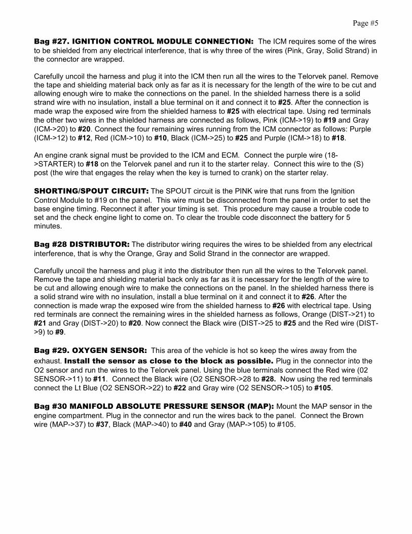
Bag #27. IGNITION CONTROL MODULE CONNECTION: The ICM requires some of the wiresto be shielded from any electrical interference, that is why three of the wires (Pink, Gray, Solid Strand) inthe connector are wrapped.
Carefully uncoil the harness and plug it into the ICM then run all the wires to the Telorvek panel. Removethe tape and shielding material back only as far as it is necessary for the length of the wire to be cut andallowing enough wire to make the connections on the panel. In the shielded harness there is a solidstrand wire with no insulation, install a blue terminal on it and connect it to #25. After the connection ismade wrap the exposed wire from the shielded harness to #25 with electrical tape. Using red terminalsthe other two wires in the shielded harness are connected as follows, Pink (ICM->19) to #19 and Gray(ICM->20) to #20. Connect the four remaining wires running from the ICM connector as follows: Purple(ICM->12) to #12, Red (ICM->10) to #10, Black (ICM->25) to #25 and Purple (ICM->18) to #18.
An engine crank signal must be provided to the ICM and ECM. Connect the purple wire (18->STARTER) to #18 on the Telorvek panel and run it to the starter relay. Connect this wire to the (S)post (the wire that engages the relay when the key is turned to crank) on the starter relay.
SHORTING/SPOUT CIRCUIT: The SPOUT circuit is the PINK wire that runs from the IgnitionControl Module to #19 on the panel. This wire must be disconnected from the panel in order to set thebase engine timing. Reconnect it after your timing is set. This procedure may cause a trouble code toset and the check engine light to come on. To clear the trouble code disconnect the battery for 5minutes.
Bag #28 DISTRIBUTOR: The distributor wiring requires the wires to be shielded from any electricalinterference, that is why the Orange, Gray and Solid Strand in the connector are wrapped.
Carefully uncoil the harness and plug it into the distributor then run all the wires to the Telorvek panel.Remove the tape and shielding material back only as far as it is necessary for the length of the wire tobe cut and allowing enough wire to make the connections on the panel. In the shielded harness there isa solid strand wire with no insulation, install a blue terminal on it and connect it to #26. After theconnection is made wrap the exposed wire from the shielded harness to #26 with electrical tape. Usingred terminals are connect the remaining wires in the shielded harness as follows, Orange (DIST->21) to#21 and Gray (DIST->20) to #20. Now connect the Black wire (DIST->25 to #25 and the Red wire (DIST->9) to #9.
Bag #29. OXYGEN SENSOR: This area of the vehicle is hot so keep the wires away from the
exhaust. Install the sensor as close to the block as possible. Plug in the connector into theO2 sensor and run the wires to the Telorvek panel. Using the blue terminals connect the Red wire (02SENSOR->11) to #11. Connect the Black wire (O2 SENSOR->28 to #28. Now using the red terminalsconnect the Lt Blue (O2 SENSOR->22) to #22 and Gray wire (O2 SENSOR->105) to #105.
Bag #30 MANIFOLD ABSOLUTE PRESSURE SENSOR (MAP): Mount the MAP sensor in theengine compartment. Plug in the connector and run the wires back to the panel. Connect the Brownwire (MAP->37) to #37, Black (MAP->40) to #40 and Gray (MAP->105) to #105.

Page #6
Bag #31.V.I.P. SELF TEST: Mount both connectors inside the vehicle under the dash and run the
wires to the Telorvek Panel. Using the red terminals connect the Tan (VIP 1->42) to #42, Gray (VIP 1->107) to #107, Pink (VIP 1->43) to #43, Lt Green (VIP 1->44) to #44, Lt Blue (VIP 1->41) to #41 and theWhite (VIP 2->45) to #45.
The remaining Lt Green & Red wires are for the dash mounted service engine soon (S.E.S) light. Thelight must be a two wire un-grounded light. Connect the Lt Green wire (44->SES LT) to #44 on theTelorvek Panel and run it to a dash indicator light and connect it to one of the wires running from thelight. The red wire (65->SES LT) connects to #65 on the panel and run to the other wire running from thelight. This light is not required as the yellow light on top of the Telorvek Panel has the same function.
E4OD Automatic Transmission Wiring
NOTE!!
If you have decided to run a manual or another type transmission wiring
bags #32, #33 and #35 will not be used. The wiring for the vehicle speed
sensor (bag #34) will be used.
Bag #32 E4OD TRANSMISSION CONNECTIONS: The E4OD transmission is a electronicallycontrolled four speed automatic transmission. Plug the connector into the transmission and run thewires to the Telorvek panel. Using the red terminals, connect the Orange wire (TRANS 7->70) to #70,Yellow (TRANS 4->73) to #73, Brown (TRANS 5->71) to #71, Gray (TRANS 8->108) to #108, Orange(TRANS 3->74 to #74, Pink (TRANS 2->72) to #72 and the White (TRANS 11->75 to #75 . Using blueterminals, connect the Red (TRANS 1->67) and the Red (TRANS 12->67) to #67.
The Purple wire (77->BRK SW) connects to #77 and runs to the cold side of the brake light switch. Thiswire should only have 12 volts with the brake pedal depressed.
Bag #33 TRANSMISSION CONTROL SWITCH (TCS) & TRANSMISSION CONTROL
INDICATOR LIGHT (TCIL): The ECM has the capability to lock-out fourth gear of the transmissionwith a push of a button. Pushing the momentary contact TCS button will light and blink the TCIL andlock-out fourth gear in the transmission for city driving. Pushing the button again will turn the TCIL offand release the lock-out allowing the transmission to shift into fourth gear for highway driving.
Mount a momentary contact switch in dash or near the shifter lever. Connect the Red wire (66->TCS) to#66 and the Tan wire (79->TCS) to #79 and run both wires to the TCS switch. You may connect thewires to either terminal on the switch.
The TCIL light must be a two wire un-grounded light. Mount the light in the dash where it is visible whiledriving. Connect the White wire (78->TCIL) to #78 and the Red wire (66->TCIL) to #66 and run bothwires to the TCIL light and make the connections.
Bag #34.VEHICLE SPEED SENSOR: On a stock vehicle application the rear anti-lock brake sensorsends a signal to the programmable speedometer/odometer module (PSOM). The module thenconverts this signal into a standard 8000 pulses per mile (8 pulses per revolution) signal all Ford ECM'Saccept. In order for the transmission to function properly this signal must be provided to the ECM.

Page #7
Speedometer cable driven eight pulse generators are available, however will have to be adapted to yourspeedometer cable. This service can be preformed at your local speedometer shop.
If you discussed using a manual or non-electronic transmission at the time of order we have applied thetypical Ford speed sensor connector to the proper wires. You can connect this to Ford Speed Sensorpart number: E9TZ-9E731-A. This sensor can be adapted to most C4, C6, AOD and manualtransmissions.
After mounting the generator connect the (VSS HIGH->80) to #80 and run it to the signal output wirefrom the generator. Connect the (VSS LOW->28) wire to #28 and run it to the VSS low output wire fromthe generator. Some aftermarket generators require an ignition feed to the unit. If so connect the redwire (VSS IGN->8) to #8 and run it to the ignition input of the unit.
Electronic speedometers can be connected to terminal #80 to pick up the VSS signal. This is a standardFord 8000 pulse per mile signal.
Bag #35 MANUAL LEVER POSITION SWITCH (MLPS) : The manual lever position switch islocated on the left hand side of the transmission. The MLPS controls neutral safety, back-up and leverposition functions. We have included wires in the MLPS connector to allow you to get full use out of theswitch. Connect the circuits in the switch as follows:
NEUTRAL / SAFETY: The heavier gauge Lt Blue (IGNITION SW->) and the Purple (START SOL->)wires are for the neutral safety circuit. Locate the wire that runs from the ignition switch to the startersolenoid. Cut the wire and connect the Lt Blue wire (IGNITION SW->) to the wire running from theignition switch and the Purple wire (START SOL->) to the wire running from the starter solenoid. NOTE:If you are wiring this circuit to one of our Component Panel wiring kits, these wires will be a color forcolor match.
BACK-UP LIGHTS: Connect the Dk Green wire (BACK UP LT FEED) to a 12 volt ignition source. This wire should have 12 volts only with the key in the run position. Run the other Dk Green wire (TOBACK UP LTS) to the rear of the vehicle and connect it to both back-up lights. The lights must begrounded.
LEVER POSITION CIRCUIT: Run the Yellow and Gray wires to the Telorvek panel. Using the red
terminals, connect the Yellow wire (MLPS->76) to #76 and the Gray wire (MLPS->107) to #107.
Bag #36 FUEL PUMP, INERTIA SWITCH & FUEL PUMP RELAY: We have included thewiring necessary for the Ford inertia switch. The inertia switch cuts off the electric fuel pump in theadvent of an accident. Mount the inertia switch in the rear of the vehicle in a dry area. Using the blueterminals, plug in the connector to the inertia switch and run the Tan wire (INERTIA SW->81) to #81 onthe Telorvek panel. Run the other Tan wire (INERTIA SW->PUMP) to the electric fuel pump. Hook thewire to the positive terminal on the pump. From the negative terminal on the pump connect a wire andrun it to a good ground.
NOTE: The inertia switch has a red button on top of it that must be set (pushed down) in order for thefuel pump to operate. If the pump fails to operate check the inertia switch making sure the red button isin the down position.
FUEL PUMP RELAY: Mount the relay within "30" inches of the Telorvek panel. Connect the Yellow
wire (FP RELAY->68) to #68, Tan (FP RELAY->81) to #81, Red (FP RELAY->64) to #64 and Lt Blue(FP RELAY->41) to #41.
For fuel pump relay use Ford part number F8PZ-14N135-AA or Motorcraft DY-864.

Page #8
Bag #37 EGR SOLENOID (EGR), AIR DIVERT & AIR BYPASS SOLENOIDS, CANISTER
PURGE SOLENOID:
EGR: Plug the connector into the EGR solenoid. Using the red terminals run the Red wire (EGR SOL-
>6) to #6 and the Brown wire (EGR SOL->46) to #46.
AIR DIVERT & AIR BYPASS SOLENOIDS: Controlled by the ECM, these solenoids control thefresh air flow into the exhaust reducing the hydrocarbon and carbon monoxide content of the exhaust.
BYPASS SOLENOID: Plug the connector into the bypass solenoid and run the wires to the panel.
Using the red terminals connect the Red wire (BYPASS SOL->5) to #5 and the White wire (BYPASSSOL->48) to #48.
AIR DIVERT SOLENOID: Plug the connector into the air divert solenoid and run the wires to the
panel. Using the red terminals connect the Red wire (DIVERT SOL->6) to #6 and the Brown wire(DIVERT SOL->47) to #47.
CANISTER PURGE SOLENOID: Plug the connector into the Canister Purge Solenoid. Using red
terminals connect the Red wire (CAN PURGE->5) to #5 and the Gray wire (CAN PURGE->49) to #49using a red terminal.
L NOTE 7The two remaining wiring bags (#38 & #39) are only to be used on 5.0
engines.
Bag #38 KNOCK SENSOR (5.0 ENGINES ONLY): The knock sensor signals the ECM to retardtiming if engine knocks during operation. Plug the connector into the sensor and run the wires back tothe panel. Connect the yellow wire (KNOCK->23) to #23 and the gray wire (KNOCK->103) to #103.
Bag #39 POWER STEERING SWITCH (5.0 ENGINES ONLY, WITHOUT E4OD
TRANSMISSIONS) The power steering switch ONLY is used with a manual transmission. It mountsin the high pressure line running from the power steering pump to the steering box. The switch signalsthe ECM when power steering pressure is above 350 psi + 50. The engine then increases idle speed tocompensate for the additional load.
Plug the connector into the switch and run the wires back to the panel. Connect the Lt Green wire(PWR STR SW->24) to #24 and the Gray wire (PWR STR SW->103) to #103.

Page #9
FINISHING UP
Connect the large pre-wired orange wire to the ignition circuit of your ignition switch. This is an ignitionfeed that is controlled by the ignition switch. This is not an accessory feed and must remain hot evenwhen the engine is cranking.
Connect the large pre-wired red battery feed wire to a battery feed. This is a battery feed that mustremain hot even with the key off. Make sure this is a good connection. If you have a Master Disconnectswitch, install this wire on the battery side of the switch so it will remain hot with the Disconnect off.
The black ground wire from the TELORVEK Panel runs direct to the battery. Run the battery grounddirectly to the engine not the frame first.This includes rear mounted batteries.
STARTING THE ENGINE
You have now made all of the connections necessary to TRY to start your car. If you try now, you will bedisappointed since you did not hook up the battery. You can do so now.
Priming the Fuel System
The fuel system can be primed by grounding the fuel pump lead in the V.I.P Self Test Connector. Thislead is a Lt Blue wire (VIP 1->41) located in the large V.I.P Test connector on the short end of theconnector. With the key off, run a jumper wire from the connector to ground. Turn the key on and
carefully bleed off any air pressure at the schrader valve until fuel runs out. CARE SHOULD BE
TAKEN TO AVOID ANY SPILLAGE WHILE FOLLOWING THIS PROCEDURE. After makingsure all the air is out of the lines, turn the key off and remove the jumper wire.
Initial Timing Procedure
(1) Transmission in Park.(2) Connect an inductive timing light.(3) Disconnect the PINK wire connected to panel number 19. Do not let it touch anything. (4) With the engine running check/adjust timing.(5) Shut the engine off, reconnect the PINK wire to panel number 19 and check for timing advance
to verify distributor is advancing beyond the initial setting.
We're trying...
Ron Francis Wiring has made every effort to assure a quality product and can assure you that thissystem works well in your application. Most of the 'problem' calls we have had to date are basic troubleshooting questions which have nothing to do with the TELORVEK system we sold you.
We are committed to offering the most user friendly wiring systems available and support this with manyyears experience in the wiring and fuel injection fields. Please be certain that all connections are correctand tests run before calling. Your unit can be tested at any Ford Motor Company Dealership with nodifficulty.

Page #10
USING THE CHECK ENGINE LIGHT
The check engine light performs just the same as it would in any newer car, when the key is turned on(engine not running) the light will stay on until the engine starts. When the check engine light comes onduring engine operation, it is an indication of a fault in the system. It will be necessary to have thecomputer perform a self test diagnostic procedure. The self test is divided into three specialized tests:
KEY ON ENGINE OFF SELF TEST (KOEO) : For this test the fault must be present at the time oftesting. For intermittent , refer to continuous memory codes.
ENGINE RUNNING ("R") SELF TEST: The sensors are checked under operating conditions and atnormal operating temperatures.
CONTINUOUS ("C") MEMORY CODES: These codes are issued as a result of information storedwhile the vehicle was in normal operation.
READING THE CHECK ENGINE LIGHT: A service code is reported by a flash of the check enginelight. All service codes are three digit numbers, such as 112. The light will display one flash, then, after atwo second pause, the light will flash twelve times. All self test codes (if any) will be displayed and thena delay of six seconds, a single half second separator flash and another six second delay and then thecontinuous memory codes will be flashed.
If the light remains on after the engine is running then follow the procedures below to have the checkengine light flash trouble codes.
Locate the V.I.P self test connectors and connect a jumper wire between the gray wire (VIP 1->107)located in the large VIP connector and the white wire (VIP 2->45) located in the single connector asshown in the drawing below.
Trouble Code Chart
ECM
CODE
CONDITIONSKEY:
O= Key On Engine OffR= Engine RunningC= Continuous Memory
Definition
111 O R C System Pass
112 O C Intake Air Temp sensor circuit below minimum voltage
113 O C Intake Air Temp sensor circuit above maximum voltage
114 O R Intake Air Temp higher or lower than expected
116 O R Engine Coolant temp higher or lower than expected
117 O C Engine Coolant temp sensor circuit below minimum voltage
118 O C Engine Coolant temp sensor circuit above maximum voltage

Page #11
ECM
CODE
CONDITIONSKEY:
O= Key On Engine Off
R= Engine Running
C= Continuous Memory
Definition
121 O R C Closed throttle voltage higher or lower than expected
Indicates throttle position voltage inconsistent with the MAFsensor
122 O C Throttle position sensor circuit below minimum voltage
123 O C Throttle position sensor circuit above maximum voltage
124 C Throttle position sensor voltage higher than expected
125 C Throttle position sensor voltage lower than expected
126 O R C MAP / BARO sensor higher or lower than expected
128 R MAP sensor vacuum hose damaged or disconnected
129 R Insufficient MAP / Mass Air Flow change during dynamicresponse test
136 R Lack of heated oxygen sensor switch during KOER,indicates lean (Bank #2)
137 R Lack of heated oxygen sensor switch during KOER,indicates rich (Bank #2)
139 C No heated oxygen sensor switches detected (Bank #2)
144 C No heated oxygen sensor switches detected (Bank #1)
157 C Mass Air Flow sensor circuit below minimum voltage
158 O C Mass Air Flow sensor circuit above maximum voltage
159 O R Mass Air Flow higher or lower than expected
167 R Insufficient throttle position change during dynamicresponse test
171 C Fuel system at adaptive limits, heated O2 sensor unable toswitch (Bank #1)
172 R C Lack of heated O2 switches, indicates lean (Bank #1)
173 R C Lack of heated O2 switches, indicates rich (Bank #1)
175 C Fuel system at adaptive limits, heated O2 sensor unable toswitch (Bank #2)
176 C Lack of heated O2 switches, indicates lean (Bank #2)
177 C Lack of heated O2 switches, indicates rich (Bank #2)
179 C Fuel system at lean adaptive limit at part throttle, systemrich (Bank #1)
181 C Fuel system at lean adaptive limit at part throttle, systemlean (Bank #1)
184 C Mass Air Flow higher than expected
185 C Mass Air Flow lower than expected
186 C Injector pulsewidth higher than expected
Page #12
ECM
CODE
CONDITIONSKEY:
O= Key On Engine Off
R= Engine Running
C= Continuous Memory
Definition
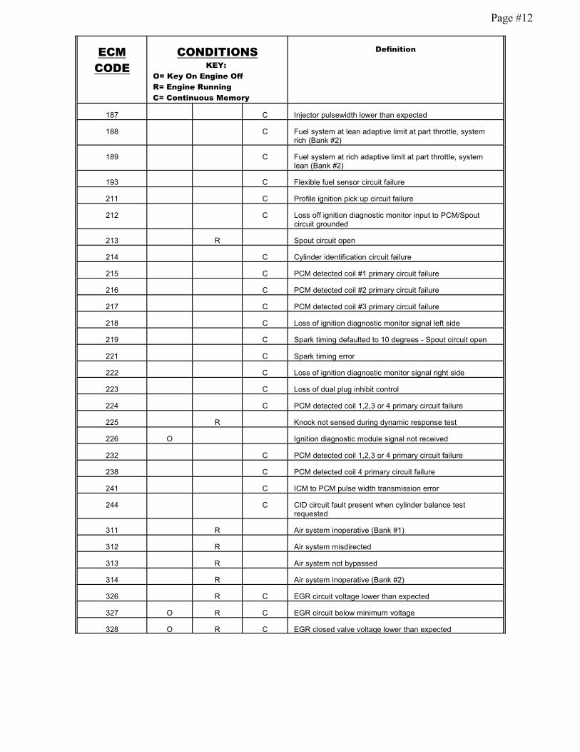
187 C Injector pulsewidth lower than expected
188 C Fuel system at lean adaptive limit at part throttle, systemrich (Bank #2)
189 C Fuel system at rich adaptive limit at part throttle, systemlean (Bank #2)
193 C Flexible fuel sensor circuit failure
211 C Profile ignition pick up circuit failure
212 C Loss off ignition diagnostic monitor input to PCM/Spoutcircuit grounded
213 R Spout circuit open
214 C Cylinder identification circuit failure
215 C PCM detected coil #1 primary circuit failure
216 C PCM detected coil #2 primary circuit failure
217 C PCM detected coil #3 primary circuit failure
218 C Loss of ignition diagnostic monitor signal left side
219 C Spark timing defaulted to 10 degrees - Spout circuit open
221 C Spark timing error
222 C Loss of ignition diagnostic monitor signal right side
223 C Loss of dual plug inhibit control
224 C PCM detected coil 1,2,3 or 4 primary circuit failure
225 R Knock not sensed during dynamic response test
226 O Ignition diagnostic module signal not received
232 C PCM detected coil 1,2,3 or 4 primary circuit failure
238 C PCM detected coil 4 primary circuit failure
241 C ICM to PCM pulse width transmission error
244 C CID circuit fault present when cylinder balance testrequested
311 R Air system inoperative (Bank #1)
312 R Air system misdirected
313 R Air system not bypassed
314 R Air system inoperative (Bank #2)
326 R C EGR circuit voltage lower than expected
327 O R C EGR circuit below minimum voltage
328 O R C EGR closed valve voltage lower than expected

Page #13
ECM
CODE
CONDITIONSKEY:
O= Key On Engine Off
R= Engine Running
C= Continuous Memory
Definition
332 R C Insufficient EGR flow detected
334 O R C EGR closed valve voltage higher than expected
335 O EGR sensor voltage higher or lower than expected
336 R C Exhaust pressure high / EGR circuit voltage higher thanexpected
337 O R C EGR circuit above maximum voltage
338 C Engine coolant temperature lower than expected(thermostat test)
339 C Engine coolant temperature higher than expected(thermostat test)
341 O Octane adjust service pin open
411 R Cannot control RPM during KOER low RPM check
412 R Cannot control RPM during KOER high RPM check
415 O R Idle air control system at maximum adaptive lower limit
416 O R Idle air control system at upper adaptive learning limit
452 C Insufficient input from vehicle speed sensor
511 O PCM read only memory test failure
512 C PCM keep alive memory test failure
513 C PCM internal voltage failure
519 O Power steering pressure switch circuit open
521 C Power steering pressure switch circuit did not change statesduring KOER
522 O Vehicle not in park or neutral during KOEO test
524 O C Low speed fuel pump circuit open (battery to PCM)
525 O Vehicle was either in gear or A/C was on during self test
527 O Park / neutral position switch circuit open or A/C on duringself test
529 C Data communication link or PCM circuit failure
532 C Cluster control assembly circuit failure
533 C Data communication link or electronic instrument clustercircuit failure
536 R C Brake on / off circuit failure / not actuated during KOER test
538 R Insufficient RPM change during KOER dynamic responsetest
539 O A/C on during self test

Page #14
ECM
CODE
CONDITIONSKEY:
O= Key On Engine Off
R= Engine Running
C= Continuous Memory
Definition
542 O C Fuel pump secondary circuit failure
543 O C Fuel pump secondary circuit failure
551 O Idle air control circuit failure
552 O Secondary air injection bypass circuit failure
553 O Secondary air injection diverter circuit failure
554 O Fuel pressure regulator control circuit failure
556 O C Fuel pump relay primary circuit failure
557 O C Low speed fuel pump primary circuit failure
558 O EGR vacuum regulator circuit failure
559 O A/C on relay circuit failure
563 O High speed fan control circuit failure
564 O Fan control circuit failure
565 O Canister Purge circuit failure
566 O 3-4 shift solenoid circuit failure
578 O R A/C pressure sensor circuit shorted (VCRM)
579 O R Insufficient A/C pressure change (VCRM)
581 O R Power to fan circuit over current (VCRM)
582 O R Fan circuit open (VCRM)
583 O R Power to fuel pump over current (VCRM)
584 O R Power ground circuit open (pin #1) (VCRM)
585 O R Power to A/C clutch over current (VCRM)
586 O R A/C clutch circuit open (VCRM)
587 O R C Variable control relay module communication failure
617 C 1-2 shift error
618 C 2-3 shift error
619 C 3-4 shift error
621 O Shift solenoid 1 circuit failure
622 O Shift solenoid 2 circuit failure
624 O C Electronic pressure control circuit failure
625 O Electronic pressure control driver open in PCM
626 O Coast clutch solenoid circuit failure
627 O C Torque converter clutch solenoid circuit failure
628 O C Excessive converter clutch slippage

Page #15
ECM
CODE
CONDITIONSKEY:
O= Key On Engine Off
R= Engine Running
C= Continuous Memory
Definition
629 O Torque converter clutch solenoid circuit failure
631 O Transmission control indicator lamp circuit failure
632 R Transmission control switch circuit did not change statesduring KOER test
634 C Manual lever position switch voltage higher or lower thanexpected
636 O R Transmission oil temp higher or lower than expected
637 O C Transmission oil temp sensor circuit above maximumvoltage (-40 F indicated circuit open)
638 O C Transmission oil temp sensor circuit below minimumvoltage (-290 F indicated circuit shorted)
639 R C Insufficient input from transmission speed sensor
641 O Shift solenoid 3 circuit failure
643 O C Torque converter clutch circuit failure
645 C Incorrect gear ratio obtained for first gear
646 C Incorrect gear ratio obtained for second gear
647 C Incorrect gear ratio obtained for third gear
648 C Incorrect gear ratio obtained for fourth gear
649 C Electronic pressure control higher or lower than expected
651 C Electronic pressure control circuit failure
652 O Torque converter clutch solenoid circuit failure
654 O Manual lever position sensor not indicating park
656 C Torque converter clutch continuous slip error
657 C Transmission over temperature condition occurred
998 C Hard fault present (FMEM mode)

Page #16
Breakout Box Circuit Diagnosis
The Telorvek panel can be used as a BREAKOUT BOX for testing circuits running to and from the EECProcessor. Listed below is the Ford circuit number, circuit description, E.E.C processor pin number,Telorvek panel number the circuit runs to, Ford wire color and the color of wire we used. Following thediagnostic procedures that can be found in the ENGINE / EMISSIONS DIAGNOSIS SHOP MANUALthat can be purchased at your local Ford dealer all trouble codes can be diagnosed.
Circuit Description EEC pin# Panel # Ford Color The Detail Zone Color
361 Ign, Air By-Pass/Canister Purge Sol 5 Red Red361 Ign, EGR Sol/Air Divert Sol 6 Red Red361 Ign, Injectors 7 Red Red361 Ign, ISC 37,57 8 Red Red16 Ign, Distributor 9 Red Red361 Ign, Positive Coil,ICM 10 Red Red687 Ign, O2 Sensor 11 Gray/Yellow Orange11 ICM, NEG Coil 12 Tan/Yellow Purple555 Inj #1, #4, #5, #8 58 13 Tan Tan556 Inj #2, #3, #6, #7 59 14 White White354 ECT 7 15 Lt Green/Red Lt Green743 IAT 25 16 Gray/Yellow Yellow264 ISC 21 17 White/Lt Blue White32 ICM, Starter Relay 18 Red/Lt Blue Purple929 ICM 36 19 Pink Pink395 ICM, Distributor 56 20 Gray/Orange Gray259 Distributor 16 21 Orange/Red Orange74 O2 Sensor 29 22 Gray/Lt Blue Lt Blue310 Knock Sensor (5.0 ONLY) 23 23 Yellow/Red Yellow330 PW Steer SW (5.0) ONLY) 24 24 Yellow/Lt Green570 GRND, Dist, ICM 25 Black/White Black48 GRND, ICM,Dist Shield 20,40 26 Clear & Black Solid & Black969 GRND 6,60 27 Black Black57 GRND, VSS, O2 Sensor 28 Black Black
351 EGRVP, TPS 26 36 Brown/White Brown351 MAP Sensor 26 37 Brown/White Brown355 TPS 47 38 Gray/White White352 EGRVP 27 39 Brown/Lt Green Lt Green264 MAP 45 40 Lt Green/Black Black926 VIP 1, FP Relay 22 41 Lt Blue/Orange Lt Blue914 VIP 1 28 42 Tan/Orange Tan915 VIP 1 9 43 Pink/Lt Blue Pink658 VIP 1, SES LT 17 44 Pink/Lt Green Lt Green209 VIP 2 48 45 White/Pink White360 EGR 33 46 Brown/Pink Brown200 Air Divert 11 47 Brown Brown190 Air By-Pass 51 48 White/Orange White101 Canister Purge Sol. 31 49 Gray/Yellow Gray
Page #17
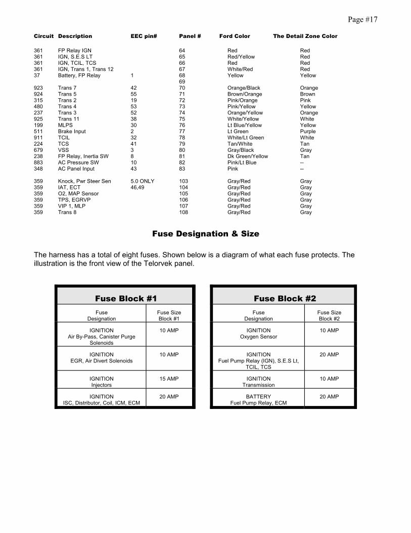
Circuit Description EEC pin# Panel # Ford Color The Detail Zone Color
361 FP Relay IGN 64 Red Red361 IGN, S.E.S LT 65 Red/Yellow Red361 IGN, TCIL, TCS 66 Red Red361 IGN, Trans 1, Trans 12 67 White/Red Red37 Battery, FP Relay 1 68 Yellow Yellow
69923 Trans 7 42 70 Orange/Black Orange924 Trans 5 55 71 Brown/Orange Brown315 Trans 2 19 72 Pink/Orange Pink480 Trans 4 53 73 Pink/Yellow Yellow237 Trans 3 52 74 Orange/Yellow Orange925 Trans 11 38 75 White/Yellow White199 MLPS 30 76 Lt Blue/Yellow Yellow511 Brake Input 2 77 Lt Green Purple911 TCIL 32 78 White/Lt Green White224 TCS 41 79 Tan/White Tan679 VSS 3 80 Gray/Black Gray238 FP Relay, Inertia SW 8 81 Dk Green/Yellow Tan883 AC Pressure SW 10 82 Pink/Lt Blue --348 AC Panel Input 43 83 Pink --
359 Knock, Pwr Steer Sen 5.0 ONLY 103 Gray/Red Gray359 IAT, ECT 46,49 104 Gray/Red Gray359 O2, MAP Sensor 105 Gray/Red Gray359 TPS, EGRVP 106 Gray/Red Gray359 VIP 1, MLP 107 Gray/Red Gray359 Trans 8 108 Gray/Red Gray
Fuse Designation & Size
The harness has a total of eight fuses. Shown below is a diagram of what each fuse protects. Theillustration is the front view of the Telorvek panel.
Fuse Block #1 Fuse Block #2
FuseDesignation
Fuse SizeBlock #1
FuseDesignation
Fuse SizeBlock #2
IGNITIONAir By-Pass, Canister Purge
Solenoids
10 AMP IGNITIONOxygen Sensor
10 AMP
IGNITIONEGR, Air Divert Solenoids
10 AMP IGNITIONFuel Pump Relay (IGN), S.E.S Lt,
TCIL, TCS
20 AMP
IGNITIONInjectors
15 AMP IGNITIONTransmission
10 AMP
IGNITIONISC, Distributor, Coil, ICM, ECM
20 AMP BATTERYFuel Pump Relay, ECM
20 AMP

Page #18
Numbered terminal block cover strip reference.
The drawing below is for your reference on the correct positioning of the Telorvek fuel injection panelterminal block cover strips.
When connecting wires to the panel be sure the numbered terminals match the drawing below.
Copyright Infringement
Ron Francis Wiring has taken the extra effort to produce a quality, easy tounderstand instructions. We will aggressively prosecute any other harnesssupplier who attempts to copy this material!!
COPYRIGHT ©1994 Ron Francis Wiring