wiwiii i 8econd quarter 1970 a1, 'o-~ - american institute of steel construction€¦ · ·...
TRANSCRIPT
WIWIII X NUMHII 2 I 8ECOND QUARTER 1970 A1, 'O-~
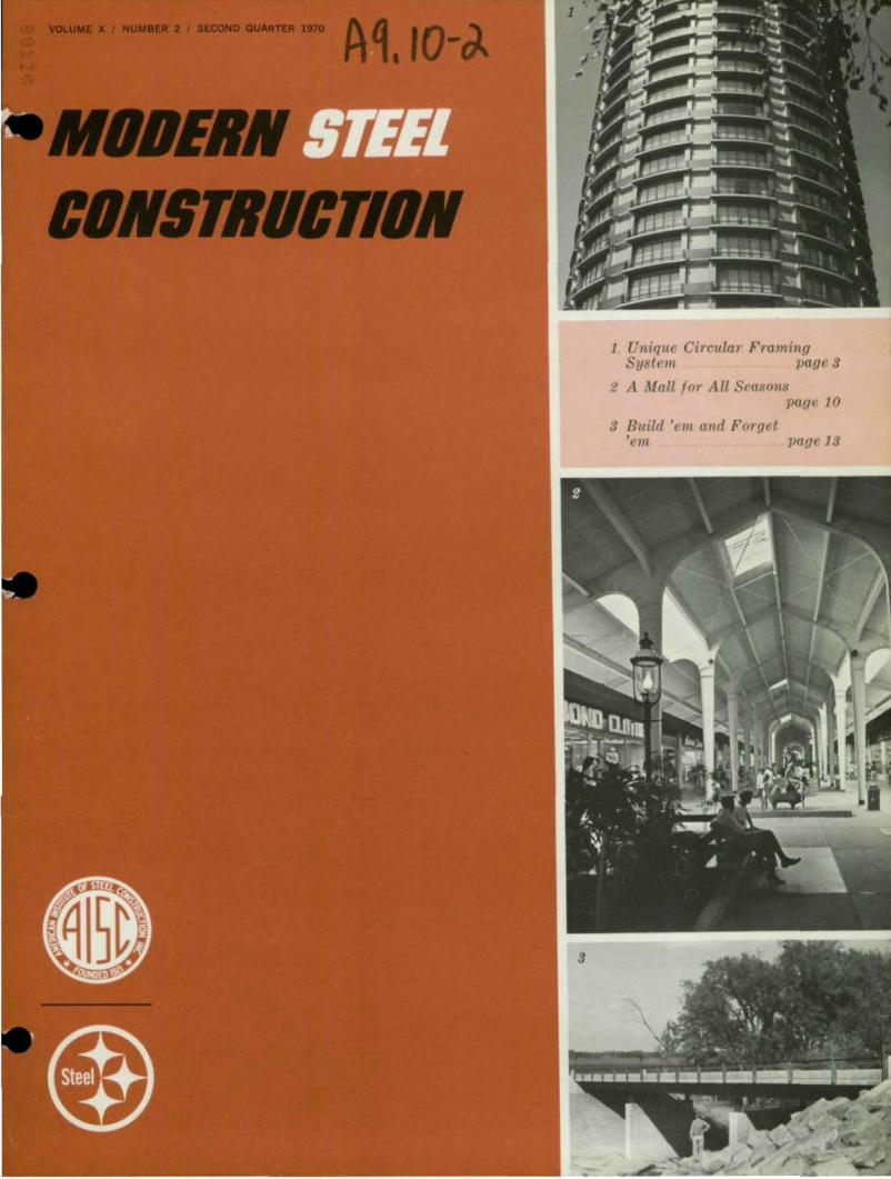
1 Unique Circular Framing System page 9
2 A Mall for All Seasons page 10
9 Build 'em and Forget 'em page 19
MODERN STEEL CONSTRUCTION Pub I ished by
American Institute of Steel Construction 101 Park Avenue, New York. N. Y. 10017
OFFICE RS
Edwin H. Webster, President Gilbert M. Dorland, First Vice President Van W. Coddington,
Second Vice President William R. Jackson, Treasurer John K. Edmonds,
Executive Vice President Leslie H. Gillette,
Assistant Executive Vice President William W. Lanigan,
Secretary and General Counsel
EDITORIAL STA ....
Daniel Farb, Editor
Mary Anne Donohue, Ass!. Editor
REGIONAL OFFICES
Atlanta, Georgia Birmingham, Alabama Boston, Massachusetts Chicago, Illinois Cleveland, Ohio Columbus, Ohio Dallas, Texas Denver, Colorado Detroit, Michigan Charlotte, North Carolina Hartford, Connecticut Houston, Texas Los Angeles, California Memphis, Tennessee Milwaukee, Wisconsin Minneapolis, Minnesota New York, New York Oklahoma City, Oklahoma Omaha, Nebraska Philadelphia, Pennsylvania Pittsburgh, Pennsylvania St. Louis. Missouri San Francisco. California Seattle, Washington Syracuse. New York Washington, District of Columbia
VOLUME x I NUMBER 2 I SECOND QUARTER 1970
CONTENTS
Unique Circular Framing System An All-Weather House by the Sea "Horizontal Skyscraper" for Boston A Mall for All Seasons Build 'em and Forget 'em
1970 ARCHITECTURAL AWARDS OF EXCELLENCE COMPETITION
3 6
8 10 13
All architecl.~ praclicill(1 prolessiollally in Ihe United States are inl'ited to submit enlries in Ihe 1.970 Architl'clu1'U1 Awards 01 Euellence Compelition. Any .• II'lI-framed bllildill(! COIl1-pletnl aller January 1, 1969 and prior 10 Seplember 1, 1970 is eligible.
The Competition will be judged by a distingllished Jllry 01 Awards including:
Rol,ert P. Burns, Jr. , AlA Head, Depal·tment of AI'chitectlLl'e, School 01 Design, North Carolina State University, Raleigh, North Carolina
Francis D. Lethbridge, FAIA Vice President 01 AlA; Keyes, Lethbl'idge & Cannon, Washington, D. C.
eyo Obata, FAIA Hellmuth, Obata & Kassabaum, Inc., St. LOllis, Misso1tli
Marjorie Phillips Chairman, Washington State A.·ts Commission, Seattle, Wa.shinglon
Lalli. W. Riggs, F.ASCE President, Tudor Engineel'ing Company, San Francisco, Calilomia
AISC-AISI COMPUTER PROGRAM FOR STEEL COLUMN DESIGN
To help meet the more sophisticaled needs 0/ today's engineering prole .• sion, AISC and AISI are del'c/oping a compllter pl'ogram lor the design 01 sleel columns. This new design aid l('iIl oller a raluable mean,~ to utiliu the com puler 10 speed selection 01 the most efficient, economical column sections lor a sintcillre and to redllce desi(!n COH/S. El'pecleci availability -lale Seplember, 1970.
For lurthel' information, conlact your local AISC "egional engineer, or write to A ISC, 101 Park Avenue, New York, N. Y. 10017.
•
•
•
•
•
unique circular framing system
by Joseph F. Moodie
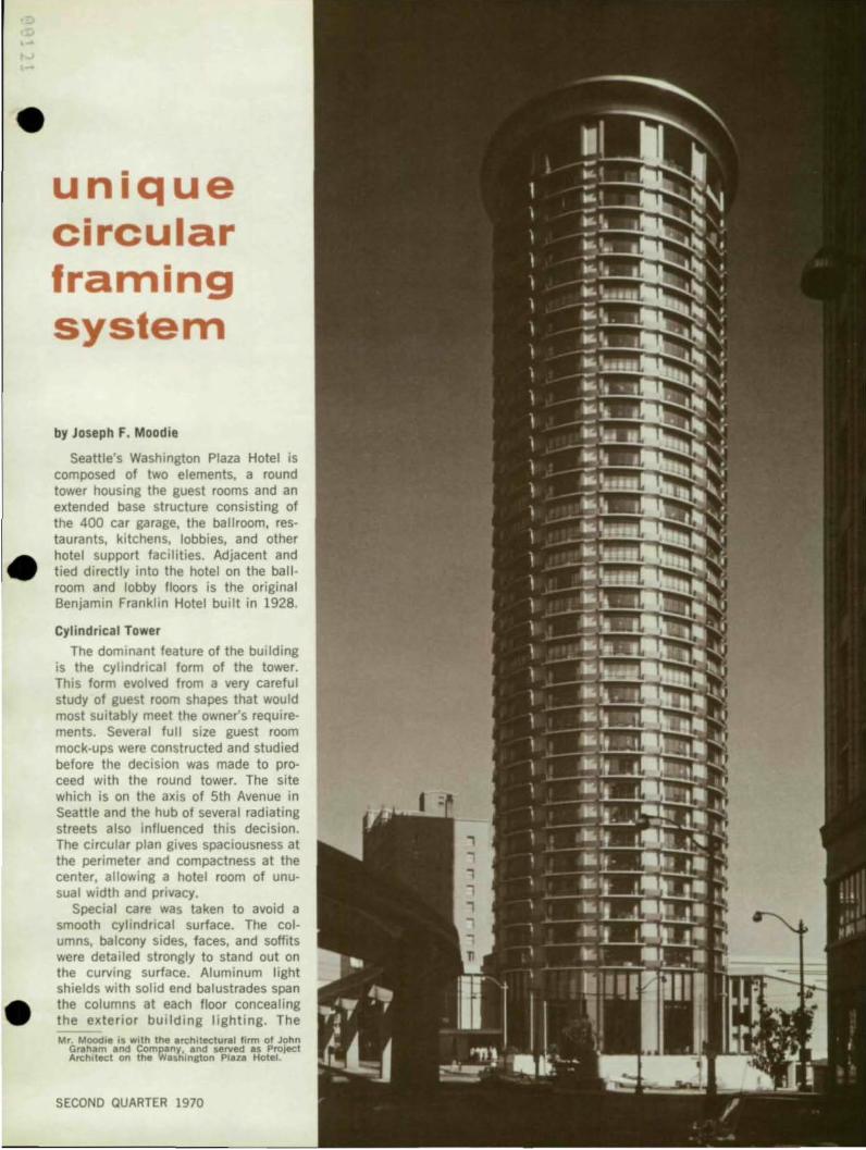
Seattle's Washington Plaza Hotel is composed of two elements, a round tower housing the guest rooms and an extended base structure consisting of the 400 car garage, the ballroom, res· taurants, kitchens, lobbies, and other hotel support facilities. Adjacent and tied directly into the hotel on the ballroom and lobby floors is the original Benjamin Franklin Hotel built in 1928.
Cylindrical Tower
The dominant feature of the building is the cyl indrical form of the tower. This form evolved from a very careful study of guest room shapes that would most suitably meet the owner's requirements. Several full size guest room mock-ups were constructed and studied before the decision was made to proceed with the round tower. The site which is on the axis of 5th Avenue in Seattle and the hub of several radiating streets also Influenced this decision. The circular plan gives spaciousness at the perimeter and compactness at the center, allowing a hotel room of unusual width and privacy.
Special care was taken to avoid a smooth cylindrical surface. The columns, balcony sides, faces, and soffits were detailed strongly to stand out on the curving surface. Aluminum light shields with solid end balustrades span the columns at each floor concealing the exterior building lighting. The Mr. Moodie is With the architectural firm of John
Graham and Company, and served as Project Architect on the WUhington Plaza Hotel.
SECOND QUARTER 1970
, ...
•
•
•
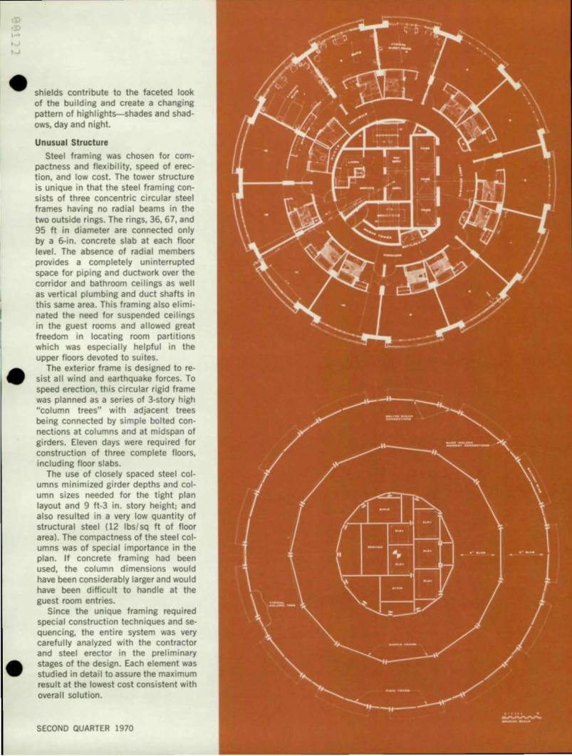
shields contribute to the faceted look of the building and create a changing pattern of highlights-shades and shadows, day and night.
Unusual Structure
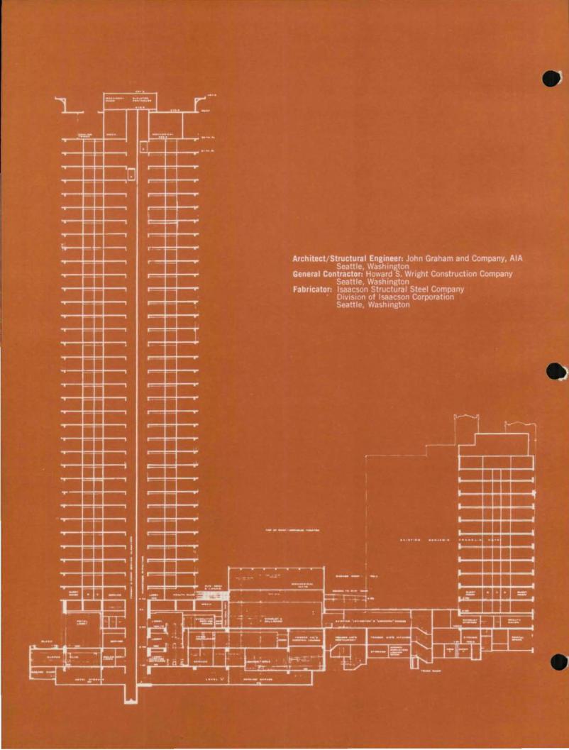
Steel framing was chosen for compactness and flexibility, speed of erection, and low cost. The tower structure is unique in that the steel framing consists of three concentric circular steel frames having no radial beams in the two outside rings. The rings, 36, 67, and 95 ft in diameter are connected only by a 6-in. concrete slab at each floor level. The absence of radial members provides a completely uninterrupted space for piping and ductwork over the corridor and bathroom ceilings as well as vertical plumbing and duct shafts in this same area. This framing also eliminated the need for suspended ceilings in the guest rooms and allowed great freedom in locating room partitions which was especially helpful in the upper floors devoted to suites.
The exterior frame is designed to resist all wind and earthquake forces. To speed erection, this circular rigid frame was planned as a series of 3-story high "column trees" with adjacent trees being connected by simple bolted connections at columns and at midspan of girders. Eleven days were required for construction of three complete floors, including floor slabs.
The use of closely spaced steel columns minimized girder depths and column sizes needed for the tight plan layout and 9 ft-3 in. story height; and also resulted in a very low quantity of structural steel (12 Ibs/sq ft of floor area) . The compactness of the steel columns was of special importance in the plan. If concrete framing had been used, the column dimensions would have been considerably larger and would have been difficult to handle at the guest room entries.
Since the unique framing required special construction techniques and sequencing, the entire system was very carefully analyzed with the contractor and steel erector in the preliminary stages of the design. Each element was studied in detail to assure the maximum result at the lowest cost consistent with overall solution.
SECOND QUARTER 1970
Architect, Joel Levinson, AlA Philadelphia, Pa.
Structural EnKineer: Joseph Hoffman and Associates Philadelphia, Pa.
General Contractor: Harry Brown Associates AtlantiC City, N. J.
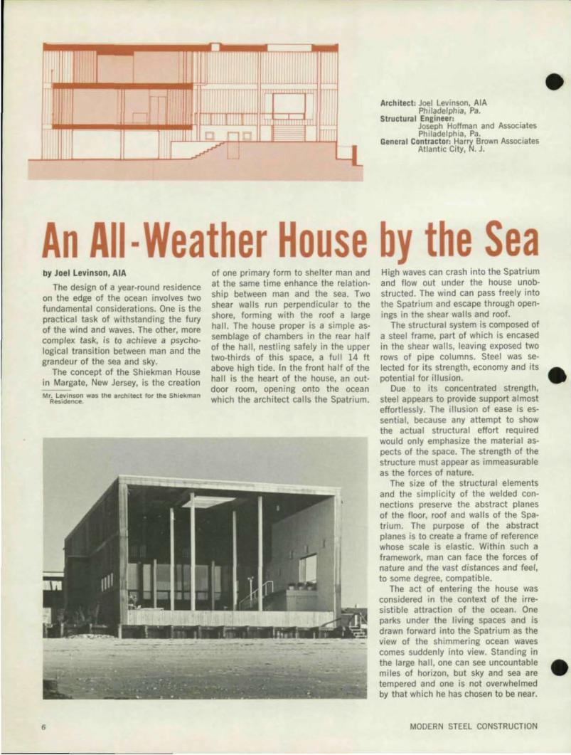
An All- Weather House by the Sea by Joel levinson, AlA
The design of a year-round residence on the edge of the ocean involves two fundamental considerations. One is the practical task of withstanding the fury of the wind and waves. The other, more complex task, is to achieve a psychological transition between man and the grandeur of the sea and sky.
The concept of the Shiekman House in Margate, New Jersey, is the creation Mr. Levinson was the architect for the Shiekman
Residence.
6
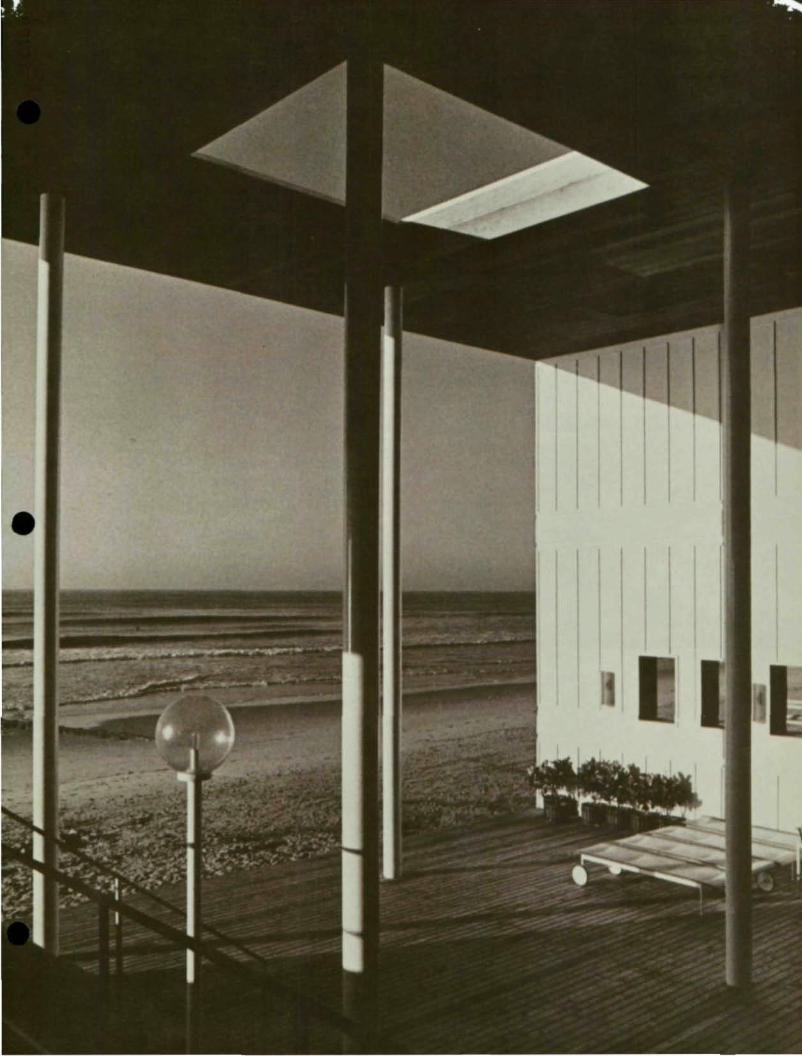
of one primary form to shelter man and at the same time enhance the relationship between man and the sea . Two shear walls run perpendicular to the shore, forming with the roof a large hall . The house proper is a simple assemblage of chambers in the rear half of the hall, nestling safely in the upper two-thirds of this space, a full 14 It above high tide. In the front half of the hall is the heart of the house, an outdoor room, opening onto the ocean which the architect calls the Spatrium.
High waves can crash into the Spatrium and flow out under the house unobstructed. The wind can pass freely into the Spatrium and escape through openings in the shear walls and roof.
The structural system is composed of a steel frame, part of which is encased in the shear walls, leaving exposed two rows of pipe columns. Steel was selecled for its strength, economy and its potential for illusion.
Due to its concentrated strength, steel appears to provide support almost effortlessly. The illusion of ease is essential , because any attempt to show the actual structural effort required would only emphasize the material aspects of the space. The strength of the struclure must appear as immeasurable as the forces of nature.
The size of the structural elements and the simplicity of the welded connections preserve the abstract planes of the 1I00r, roof and walls of the Spatrium. The purpose of the abstract planes is to create a frame of referenc~ whose scale is elastic. Within such a framework, man can face the forces of nature and the vast distances and feel, to some degree, compatible.
The act of entering the house was considered in the context of the irresistible attraction of the ocean. One parks under the living spaces and is drawn forward into the Spatrium as the view of the shimmering ocean waves comes suddenly into view. Standing in the large hall, one can see uncountable miles of horizon, but sky and sea are tempered and one is not overwhelmed by that which he has chosen to be near.
MODERN STEEL CONSTRUCTION
•
•
•
•
8
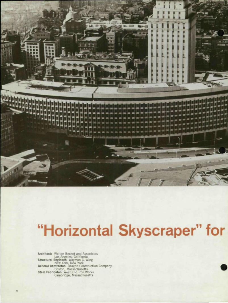
"Horizontal Skyscraper" for Architect: Welton Becket and Associates
Los Angeles, California Structural Engineer: Wayman C. Wing
New York, New York General Contractor: Beacon Construction Company
Boston, Massachusetts Steel Fabricator: West End Iron Works
Cambridge, Massachusetts •
oston
•
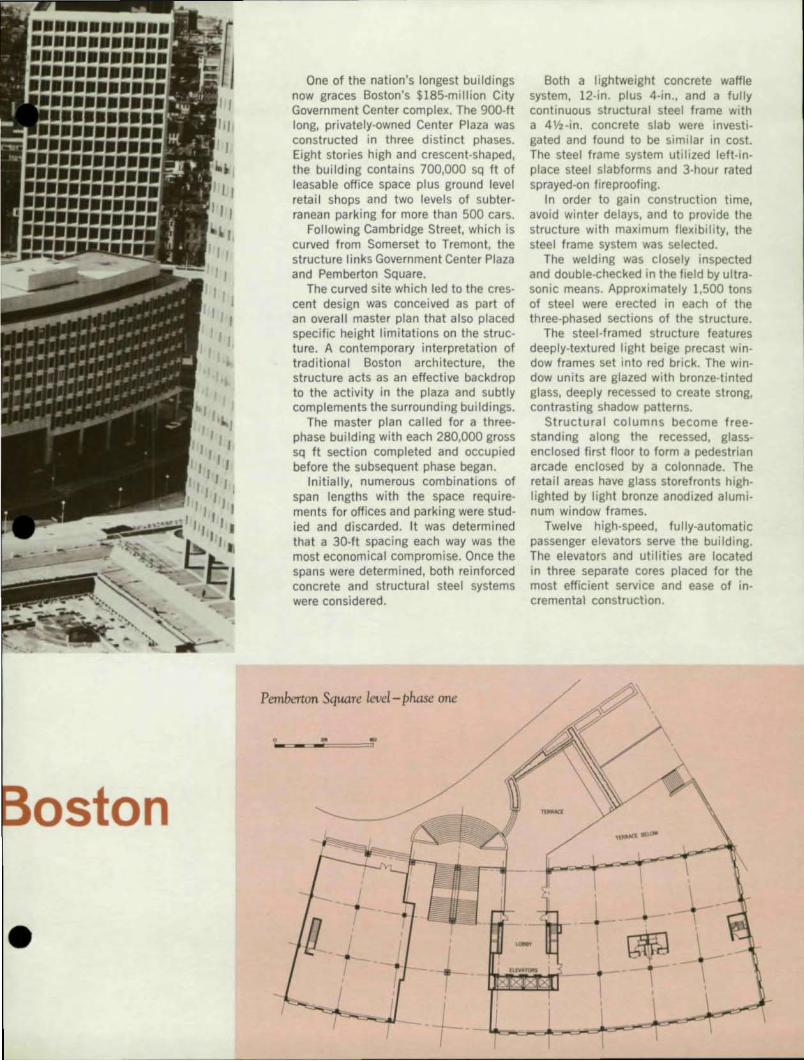
One of the nation's longest buildings now graces Boston's $185-million City Government Center complex. The gOO-It long, privately-owned Center Plaza was constructed in three distinct phases. Eight stories high and crescent-shaped, the building contains 700,000 sq It of leasable office space plus ground level retail shops and two levels of subterranean parking for more than 500 cars.
Following Cambridge Street, which is curved from Somerset to Tremont, the structure links Government Center Plaza and Pemberton Square.
The curved site which led to the crescent design was conceived as part of an overall master plan that also placed specific height limitations on the structure. A contemporary interpretation of traditional Boston architecture, the structure acts as an effective backdrop to the activity in the plaza and subtly complements the surrounding buildings.
The master plan called for a threephase building with each 280,000 gross sq It section completed and occupied before the subsequent phase began.
Initially, numerous combinations of span lengths with the space requirements for offices and parking were studied and discarded. It was determined that a 30-ft spacing each way was the most economical compromise. Once the spans were determined, both reinforced concrete and structural steel systems were considered.
Pemberton Square level- phase one
• -
Both a lightweight concrete waffle system, 12-in. plus 4-in., and a fully continuous structural steel frame with a 4 V2-in. concrete slab were investi gated and found to be simi lar in cost. The steel frame system utilized left-inplace steel slabforms and 3-hour rated sprayed-on fireproofing.
In order to gain construction time, avoid winter delays, and to provide the structure with maximum flexibility, the steel frame system was selected.
The welding was closely inspected and double-checked in the field by ultrasonic means. Approximately 1,500 tons of steel were erected in each of the three-phased sections of the structure.
The steel-framed structure features deeply-textured light beige precast window frames set into red brick. The window units are glazed with bronze-tinted glass, deeply recessed to create strong, contrasting shadow patterns.
Structural columns become freestanding along the recessed, glassenclosed first floor to form a pedestrian arcade enclosed by a colonnade. The retail areas have glass storefronts highlighted by light bronze anodized aluminum window frames.
Twelve high-speed, fully-automatic passenger elevators serve the building. The elevators and utilities are located in three separate cores placed for the most efficient service and ease of incremental construction.
• • • -i. UlV.'OItI ~ I ,
I +-
\
• •
•
• •
•
A Mall for All Seasons
· --
• • • • .. •
• PH ASE 2
·1 _M DIITM CI"{. . -..
~
• • :..,...r"i
""', .. MU ... 1l000U
, . • - -• • I • --I,
Dl_'",., lTOII(
SECONO QUARTER 1970
I I
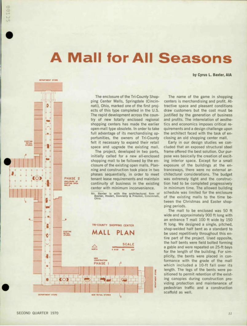
The enclosure of the Tri-County Shopping Center Malls, Springdale (Cincinnati), Ohio, marked one of the first projects of this type completed in the U.S. The rapid development across the country of new totally enclosed regional shopping centers has made the earlier open-mall type obsolete. In order to take full advantage of its merchandising opportunities, the owners of Tri-County felt it necessary to expand their retail space and upgrade the existing mall.
The project, developed in two parts, initially called for a newall-enclosed shopping mall to be followed by the enclosure of the existing open malls. Planning and construction took place in two phases sequentially, in order to meet tenant lease requirements and maintain continuity of business in the existing center with minimum inconvenience.
Mr. Baxter is with the architectural firm of Baxter, Hade!! , Donnelly & Preston, Cincinnati, Ohio.
TAt-COUNTY SHOPPING CENTER
MALL PLAN
.6- SCALE
--- .... .. --... _ ....... PHASE I (
I I I I I I §
...:W 1tC, .... IlOltlI ~
by Cyrus L. Baxter, AlA
The name of the game in shopping centers is merchandising and profit. Attractive space and pleasant conditions draw customers but the cost must be justified by the generation of business and profits. The interrelation of aesthetics and economics imposes critical requirements and a design challenge upon the architect faced with the task of enclosing an old shopping center mall.
Early in our design studies we concluded that an exposed structural steel frame offered the best solution. Our purpose was basically the creation of exciting interior space. Except for a small exposure of the buildings at the entranceways, there were no external architectural considerations. The budget was extremely tight and the construction had to be completed progressively in minimum time. The allowed building schedule was limited for the enclosure of the existing malls to the time between the Christmas and Easter shopping periods.
The mall to be enclosed was 50 ft wide and approximately 900 ft long with an entrance T mall 100 ft wide by 150 ft long. We designed a single, pitched, shop-welded half bent as a standard to be used repetitively throughout this entire part of the project. Used opposite, the half bents were field bolted forming a gable and were repeated on 25-ft bays for the length of the building. For simplicity, the bents were placed in conformance with the grade of the mall which included a 10-ft fall over its length. The legs of the bents were positioned to permit retention of the existing canopies during construction providing protection and maintenance of pedestrian traffic and a construction scaffold as well.
J J
•
12
• - -
STANOARD HAL.f BENT ,. . .. . ....
SECTIONS
[NUANCE WI. l ".
•• ING "iii I .III .. D ~
.UU<: lOW
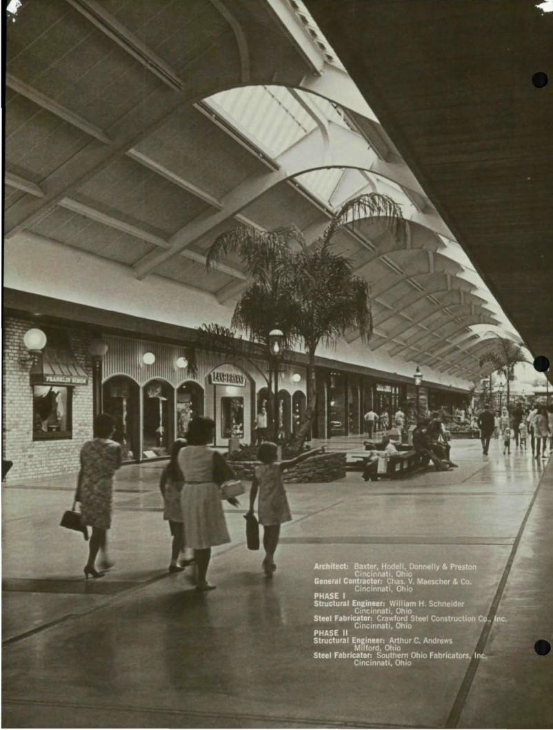
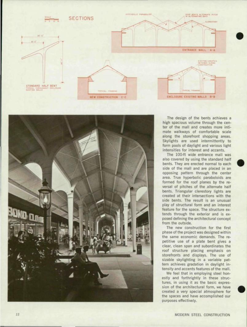
The design of the bents achieves a high spacious volume through the center of the mall and creates more intimate walkways of comfortable scale along the storefront shopping areas. Skylights are used intermittently to form pools of daylight and various light intensities for interest and accents.
The 100-1t wide entrance mall was also covered by using the standard half bents. They are erected normal to each side of the mall and are placed in an opposing pattern through the center area. True hyperbolic paraboloids are formed for the roof planes by the reversal of pitches of the alternate half bents. Triangular clerestory lights are created at their intersections with the side bents. The result is an unusual play of structural form and an interest feature for the space. The structure extends through the exterior and is exposed defining the architectural concept from the outside.
The new construction for the first phase of the project was designed within the same economic demands. The repetitive use of a plate bent gives a clear, clean span and subordinates the roof structure placing emphasis on storefronts and displays. The use of sizable skylighting in a variable pattern achieves gradation in daylight intensity and accents features of the mall.
We feel that in employing steel honestly and forthrightly in these structures, in using it as the basic expression of the architectural form, we have created a very specia I atmosphere for the spaces and have accomplished our purposes effectively.
MODERN STEEL CONSTRUCTION
•
•
•
e r.---
e
e
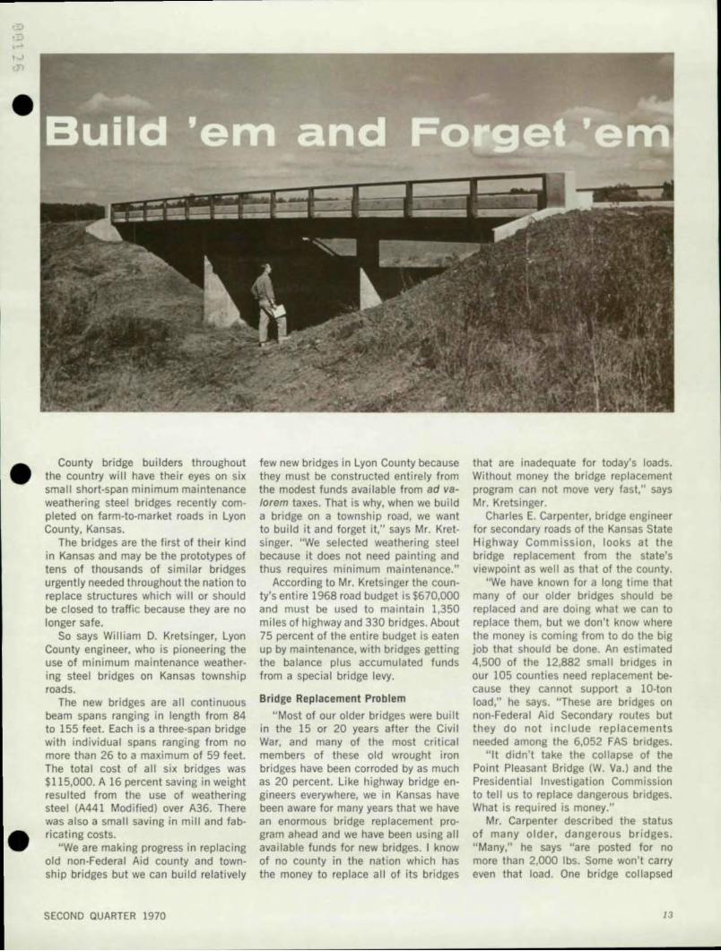
County bridge bui lders throughout the country will have their eyes on six small short·span minimum maintenance weathering steel bridges recently completed on farm-to-market roads in Lyon County, Kansas.
The bridges are the first of their kind in Kansas and may be the prototypes of tens of thousands of similar bridges urgently needed throughout the nation to replace structures which will or should be closed to traffic because they are no longer safe.
So says William D. Kretsinger, Lyon County engineer, who is pioneering the use of minimum maintenance weather· ing stee l bridges on Kansas township roads.
The new bridges are all continuous beam spans ranging in length from 84 to 155 feet. Each is a three-span bridge with individual spans ranging from no more than 26 to a maximum of 59 feet. The total cost of all six bridges was $1 15,000. A 16 percent saving in weight resulted from the use of weathering steel (A441 Modified) over A36. There was also a small saving in mill and fabricating costs.
"We are making progress in replacing old non-Federal Aid county and township bridges but we can build relative ly
SECOND QUARTER 1970
few new bridges in Lyon County because they must be constructed entirely f rom the modest funds available from ad valorem taxes. That is why, when we build a bridge on a township road, we want to build it and forget it," says Mr. Kretsinger. "We selected weathering steel because it does not need painting and thus requi res minimum maintenance."
According to Mr. Kretsinger the county's entire 1968 road budget is $670,000 and must be used to maintain 1,350 miles of highway and 330 bridges. About 75 percent of the entire budget is eaten up by maintenance, with bridges getting the balance plus accumulated funds from a special bridge levy.
Bridge Replacement Problem
"Most of our older bridges were built in the 15 or 20 years after the Civil War, and many of the most critical members of these old wrought iron bridges have been corroded by as much as 20 percent. Like highway bridge engineers everywhere, we in Kansas have been aware for many years that we have an enormous bridge replacement program ahead and we have been using all available funds for new bridges. I know of no county in the nation which has the money to replace al l of its bridges
that are inadequate for today's loads. Without money the bridge replacement program can not move very fast," says Mr. Kretsinger.
Charles E. Carpenter, bridge engineer for secondary roads of the Kansas State Highway Commission, looks at the bridge replacement from the state's viewpoint as well as that of the county.
"We have known for a long time that many of our older bridges should be replaced and are doing what we can to replace them, but we don't know where the money is coming from to do the big job that should be done. An estimated 4,500 of the 12,882 small bridges in our 105 counties need replacement because they cannot support aID-ton load," he says. "These are bridges on non-Federal Aid Secondary routes but they do not include replacements needed among the 6,052 FAS bridges.
"It didn't take the collapse of the Point Pleasant Bridge (W. Va.) and the Presidential Investigation Commission to tell us to replace dangerous bridges. What is required is money."
Mr. Carpenter described the status of many older, dangerous bridges. "Many," he says "are posted for no more than 2,000 Ibs. Some won't carry even that load. One bridge collapsed
13
Weathering Steel for New Bridges
Mr. Frazier recommended the use of weathering steel for these short-span bridges because it did not require painting and thus qualified as a "2M" bridge construction material. His firm then
;. produced preliminary designs first for a typical bridge with A36 and then the same bridge with A441 modified. The bridge was No. lOS. The designs indicated that 16 percent of the weight of the structural steel would be saved through the use of the high strength low alloy A441 modified steel. Mill and fabricating costs were checked, showing that some small savings might also be gained from the use of A441 modified. In his subsequent examination of the bridge proposals, Mr. Carpenter felt that
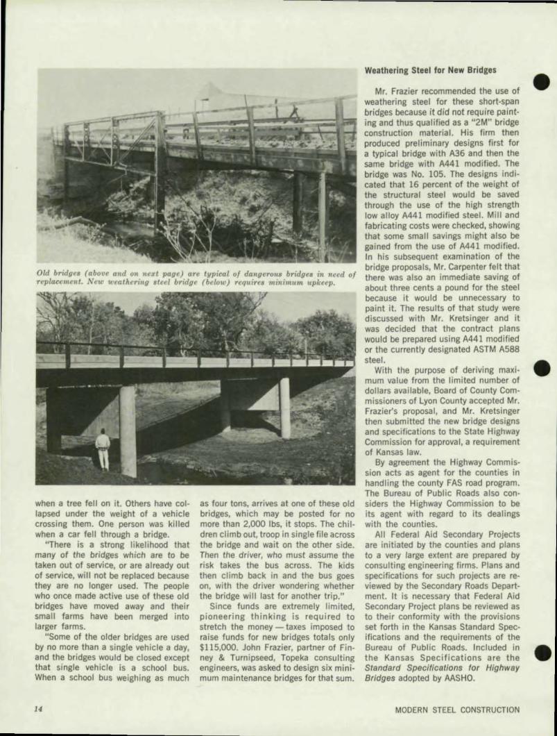
Old bridgr' (above and on 'l('xt page) ar, typical 01 da)lgcrouB bridgcs in need of there was also an immediate saving of Tcpiaccmrllt. Neu' t(,l'athcring .teel bTl'clge (below) require. minimum upkccp.
about three cents a pound for the steel
when a tree fell on it. Others have collapsed under the weight of a vehicle crossing them. One person was killed when a car fell through a bridge.
"There is a strong likelihood that many of the bridges which are to be taken out of service, or are already out of service, will not be replaced because they are no longer used. The people who once made active use of these old bridges have moved away and their small farms have been merged into larger farms.
"Some of the older bridges are used by no more than a single vehicle a day, and the bridges would be closed except that single vehicle is a school bus. When a school bus weighing as much
14
as four tons, arrives at one of these old bridges, which may be posted for no more than 2,000 Ibs, it stops. The children climb out, troop in single file across the bridge and wait on the other side. Then the driver, who must assume the risk takes the bus across. The kids then climb back in and the bus goes on, with the driver wondering whether the bridge will last for another trip."
Since funds are extremely limited, pioneering thinking is required to stretch the money - taxes imposed to raise funds for new bridges totals only $115,000. John Frazier, partner of Finney & Turnipseed, Topeka consulting engineers, was asked to design six minimum maintenance bridges for that sum.
because it would be unnecessary to paint it. The results of that study were discussed with Mr. Kretsinger and it was decided that the contract plans would be prepared using A441 modified or the currently designated ASTM A588 steel.
With the purpose of deriving maximum value from the limited number of dollars available, Board of County Commissioners of Lyon County accepted Mr. Frazier's proposal, and Mr. Kretsinger then submitted the new bridge designs and specifications to the State Highway Commission for approval, a requirement of Kansas law.
By agreement the Highway Commission acts as agent for the counties in handling the county FAS road program. The Bureau of Public Roads also considers the Highway Commission to be its agent with regard to its dealings with the counties.
All Federal Aid Secondary Projects are initiated by the counties and plans to a very large extent are prepared by consulting engineering firms. Plans and specifications for such projects are reviewed by the Secondary Roads Department. It is necessary that Federal Aid Secondary Project plans be reviewed as to their conformity with the provisions set forth in the Kansas Standard Specifications and the requirements of the Bureau of Public Roads. Included in the Kansas Specifications are the Standard Specifications for Highway Bridges adopted by AASHO.
MODERN STEEL CONSTRUCTION
•
•
•
•
•
•
Upon meeting the criteria, the plans are approved for construction and the state advances the project to contract. The state provides inspection for all Federal Aid Secondary Projects and includes these projects in their normal letting procedures.
Bridge plans for structures that are built in counties and townships are submitted to the Highway Commission for review and approval when the county engineer estimates the cost of the structure will exceed $10,000. The Lyon County bridges became the responsibility for review and approval by the Secondary Road Department.
The proposal arrived at an opportune time. Mr. Carpenter, bridge engineer for secondary roads, was aware that John D. Montgomery, director of highways, and his staff were anxious to acquire more experience with the use of weathering steel on highway bridges and overpasses.
The Lyon County bridges were carefully studied and approved, and shortly thereafter, a seventh bridge, the 208-ft bridge of weathering steel over the Wakarusa River in Shawnee County, was also approved. All seven were constructed of A441 modified weathering steel since neither AASHO nor the Bureau of Public Roads had at that time established specifications for A588 weathering steel, which is now generally used for highway bridges and overpasses. All seven bridges were funded entirely by the two counties concerned since none of the bridges are on the Federal Aid System.
SECOND QUARTER 1970
The six Lyon County bridges were put out to bid, with Russell Ralph Company of Topeka the successful bidder. The Wakarusa River bridge, designed by Kenneth E. Strobel, partner in the Topeka consulting engineering firm of Cook, Flatt & Strobel, was constructed by the Fred Beachner Company.
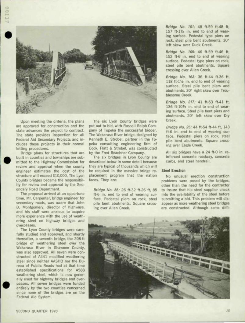
The six bridges in Lyon County are described below in some detail because they are typical of thousands which will be required in the massive bridge replacement program that the nation faces. They are,
Bridge No. 56: 26 ft-32 ft-26 ft, 85 ft-6 in. end to end of wearing surface. Pedestal piers on rock, steel pile bent abutments. Square crossing over Allen Creek.
Bridge No. 101: 48 ft-59 ft-48 ft, 157 ft-l Y2 in. end to end of wearing surface. Pedestal type piers on rock, steel pile bent abutments. 30' left skew over Duck Creek.
Bridge No. 105: 46 ft-59 ft-46 ft, 152 ft-6 in. end to end of wearing surface. Pedestal type piers on rock, steel pile bent abutments. Square crossing over Allen Creek.
Bridge No. 163: 36 ft-44 ft-36 ft, 118 ft-l Y2 in. end to end of wearing surface. Steel pile bent piers and abutments. 30' right skew over Troublesome Creek.
Bridge No. 217: 41 ft-53 ft-41 ft, 136 ft-l0Y, in. end to end of wearing surface. Steel pile bent piers and abutments. 20' left skew over Dry Creek.
Bridge No. 25: 44 ft-54 ft-44 It, 143 ft-6 in. end to end of wearing su rface. Pedestal piers on rock, steel pile bent abutments. Square crossing over Eagle Creek.
All six bridges have a 24 It-O in. reinforced concrete roadway. concrete curbs, and steel handrail.
Steel Erection
No unusual erection construction problems were posed by the bridges, other than the need for the contractor to insure that his steel supplier check into the availability of the steel before submitting a bid. This problem will disappear as more weathering steel bridges are constructed. Although some diffi-
IS
cultles were experienced, the contractor received all of the steel in time to meet his erection schedules.
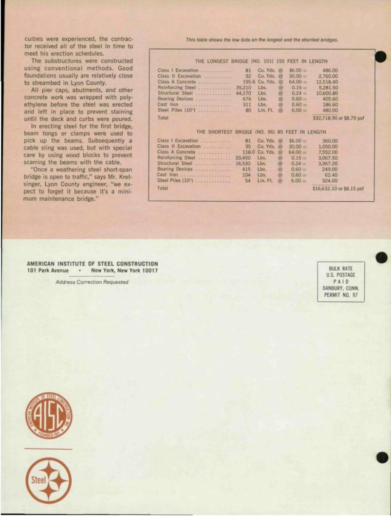
ThIS table shows the low b;ds on the longest end the shortest bridges.
The substructures were constructed using conventional methods. Good foundations usually are relatively close to streambed in Lyon County.
THE LONGEST 8RIOGE (NO. lOll 155 FEET IN LENGTH
All pier caps, abutments, and other concrete work was wrapped with polyethylene before the steel was erected arid left in place to prevent staining until the deck and curbs were poured.
In erecting steel for the first bridge, beam tongs or clamps were used to pick up the beams. Subsequently a cable sling was used, but with special care by using wood blocks to prevent scafflng the beams with the cable.
"Once a weathering steel short-span bridge is open to traffic," says Mr. Kretsinger, Lyon County engineer, "we ex· pect to forget it because it's a minimum maintenance bridge."
Class I Excavation Class II Excavation Class A Concrete •. Reinforcing Steel Structural Steel Bearing Devices Cast Iron Steel Piles (10")
Total
81 Cu. Yd •. @ 92 Cu. Yd •. @
195.6 Cu. Yd •. @ 35,210 Lb.. @ 44,170 Lb.. @
676 Lb.. @ 311 Lb.. @
80 Lon. Ft. @
$6.00 30.00 64.00
0.15 0.24 _ 0.60 : 0.60 6.00
THE SHORTEST 8RIOGE (NO. 56) 85 FEET IN
Class I Excavation 81 Cu. Yds. @ 56.00 Class II Excavation 35 Cu. Yds. @ 30.00 := Class A Concrete 118.0 Cu. Yds. @ 64.00 Reinforcing Steel 20,450 lbs. @ 0.15 Structural Steel 16,530 Lbs. @ 0.24 Bearing Deyices .•.• . •... . •.. 415 Lbs. @ 0.60 Cast Iron .. . ...... ......... 104 Lbs. @ 0.60 Steel Pile. (10-) ••. •••• ,',... 54 Lin. Ft. @ 6.00
Total
AMERICAN INSTITUTE OF STEEL CONSTRUCTION 101 Park Avenue New York, New York 10017
Address Correction Requested
486.00 2,760.00
12,518.40 5,281.50
10,600.80 405.60 186.60 480.00
532,718.90 or $8.79 pst
LENGTH
360.00 1,050.00 7,552.00 3,067.50 3,967.20
249.00 62.40
324.00
$16,632.10 or $8.15 pst
BULK RATE US. POSTAGE
PAID OANBURY. CONN. f'[RMIT NO. 97
•
•