wizard manual - home - sloan lubrication systems · the wizard monitor is designed to provide...
TRANSCRIPT

Wizard Manual
WIZARD MANUAL

SLOAN LUBRICATION SYSTEMS

www.SloanLubrication.com | 1.800.722.0250
ContentsOverview 2
Front Panel 2
Rear Panel 3
Specifications 3
Quick Start 4
Installation 6
Programming 7
Status Displays 8
Main Menu 9
Main Settings 10
Zone Settings 12
Diagnostics 15
Network Settings 17
Modbus Settings 18
Modbus Memory Map 19
Web Based Remote HMI 21
Menu Map 22
Operation 24
TDS (Total Display Switch) 25
Usage Examples 26
Troubleshooting 30
Data Logging 34
Software Updates 36
Contact Information 37

SLOAN LUBRICATION SYSTEMS2
Wizard Manual | Overview
OverviewThe Wizard monitor is designed to provide constant monitoring of your lubrication system, thereby protecting the critical lubricated equipment. It gives operators an easy to see and understand indication of the current system status and flow rate. The Wizard can monitor up to 4 zones of lubrication and provides an independent alarm circuit for each zone.
In each zone, an input from a divider block proximity switch or other
metering device, combined with the known displacement per cycle of
that input, allows for calculation of the flow rate and
ensures that the flow rate stays above a set point. If the flow rate
drops, an alarm relay changes state and, depending on how the zone
is configured, either stays there until it is manually reset or resets
automatically once normal flow resumes.
New features in the Wizard monitor include a 3.5” color LCD
touchscreen, easy setup menus, color status LEDs, and data logging
capabilities. The software in the Wizard is upgradeable in the field
through the USB port. Updates occasionally will be available on
our website.
Front PanelThe Front panel of the Wizard contains the LCD screen, the status LEDs, a USB connection, and 8 buttons.
Each of the 8 buttons corresponds to a button or location on the
screen. If there is an “A” label on the screen, press the A button to
select that option. The operator can also touch the screen itself to
select the same option. This allows an operator to use the basic
functions of the monitor without getting the screen dirty. Some menu
items are only accessible by touching the screen itself; thus they do
not have a corresponding number or letter label. Details for each
menu item and screen are located in the “Programming” section later
in this manual. Examples of common usage scenarios are located in
the “Operation” section.Front Panel

www.SloanLubrication.com | 1.800.722.0250 3
SpecificationsPower supply 90-264 VAC, 47-63 Hz / 12-48VDC 15W Max
Inputs
4 - Zone Proximity switches (low voltage
dry contact)
1 – TDS (low voltage dry contact)
1 – Arm/Disarm Circuit (low voltage dry
contact)
2 - 4-20mA Analog
Outputs
4 - Zone Alarm Relays 250V Max
5A(NO)/3A(NC)
1 - Power Fail Relay 250V Max
5A(NO)/3A(NC)
1 – 4-20mA Analog (future)
Communication
1 - RS485 Modbus Slave
1 – 10/100 Ethernet
Storage
Onboard 256MB – minimum 2 years of
logging @ 1 entry / minute.
External USB – CSV file format
Rear PanelThe rear panel of the Wizard contains all of the electrical connections as shown below. At a minimum, the Wizard needs power and a single zone input to function properly.
Power can be supplied as either AC or DC. See the specifications for
acceptable voltage ranges. The zone inputs are dry contact type
connection either relay contacts or magnetic reed switches to these
inputs will make them function properly. Do not apply external
voltage to the arm/disarm, TDS, or zone input contacts, as this may
damage the Wizard. The TDS input is used temporarily to display
the total flow for each active zone as well as reset any alarms. The
arm/disarm input is used to remotely arm or disarm the alarm
function of the monitor. Each input is explained in more depth in
the “Operation” section
Rear Panel

SLOAN LUBRICATION SYSTEMS4
Wizard Manual | Quick Start
STEP 2. PROGRAM ZONESMinimum settings required for operation
· Divider block displacement
· Low flow setpoint
· Warning to alarm value (0 to disable warning)Zone Inputs
DC Power
AC Power
Alarm Outputs
Quick StartSTEP 1. WIRE POWER, INPUTS, AND OUTPUTSAt minimum:

www.SloanLubrication.com | 1.800.722.0250 5
STEP 3. ENABLE ZONESTouch the square button to enable or disable a zone.
The corresponding LED will light, indicating the zone
is enabled.
STEP 4. TEST ALARMS
• Disconnect / disable prox switch
• Observe warning, then alarm
• Check shutdown circuit
-OR-
• While running, set low flow to high value
• Ensure automatic shutdown occurs

SLOAN LUBRICATION SYSTEMS6
Wizard Manual | Installation
InstallationThe Wizard mounts in either a JIC style enclosure or a hazardous
location enclosure with at least a 5-3/8” diameter opening. If
providing your own enclosure, please ensure that the Wizard
monitor will be protected from excessive moisture and dust.
To install, remove all electrical plugs that will be used from the rear
panel. Make sure the power supply is turned off and install each
supplied plug onto the wires.
For the screw connectors, strip the insulation from the end of each
wire, insert the wire into the connector, and tighten the screw. Make
sure there are no stray wire strands that can make an inadvertent
connection to another wire.
After all electrical connections are made, connect the plugs to the
back of the monitor and mount the monitor in the enclosure. The
Wizard is secured by two 10-32 thumb screws. It is not necessary
to make these screws extremely tight, but they should be snug.
Test the power to make sure that the connections were made
properly and, if possible, test each input.
CAUTIONTesting the relay output and shutdown functionality with the control system is imperative before putting a Wizard into service.
If assistance is needed with this procedure, look to our electrical
controls department or contact Sloan.
A Wizard installed in a JIC enclosure is shown above.

www.SloanLubrication.com | 1.800.722.0250 7
ProgrammingSeveral pieces of information are necessary to program the Wizard
monitor. First, know the displacement of the divider block or
metering device. The displacement tells the wizard how much fluid
has been delivered for each cycle of the block.
For a divider block that is measured in cubic inches (in3), the
displacement is calculated by taking the displacement values
of each divider section, adding those numbers together and
doubling the result. Divider block face values are usually written in
thousandths of a cubic inch (in3). For example, a 12T, 6T, 9T block
would have a displacement of (0.012 + 0.006 + 0.009) * 2 = 0.054in3.
The next piece of information needed is the desired flow rate. For
most applications, we recommend using half of that flow rate as
the alarm limit. So, if the desired flow rate is 20 pints / day, the low
flow setpoint should be set to 10 pints / day. When the monitored
flow rate drops below this value, an alarm will be triggered.
To get started, the screen to right is the screen that will be
displayed when the monitor first starts up. The top status bar
indicates that the Wizard is armed and in regular operation, and
the current flow rate for each zone is displayed. If the bar says TDS,
the large number is the accumulated volume since last reset. If the
bar is red and reads “Control Disarmed”, the Wizard is disarmed and
the alarm relays will not trip.
Flow information is displayed in the middle section of the screen.
When only one zone is enabled, the display defaults to the detailed
screen shown to the right. When multiple zones are enabled, only
the flow rate is displayed for each zone. The large number on the
left is the flow rate, the description of the zone is to the right, and
the selected display unit is below that. The flow rate value will
change color corresponding with that zone’s current status.
Pressing either the 1 or 2 button or touching the “Menu”
button on the main status display screen will return the screen
to the main menu.
One cycle is defined by the time it takes for the switch to close, open, and then close again. This is also known as the time between rising edges of the input signal.
An example of the status screen for Zone 1 when it is the only active zone.

SLOAN LUBRICATION SYSTEMS8
Wizard Manual | Programming
Active Zones
Each active zone flow rate is displayed in a color corresponding to its
status. The zone description and selected units are also displayed.
If only one zone is active, only the detail screens shown below will be
visible.
Zone Alarm
When a zone is in alarm, its color flashes to make the alarm
more visible.
Zone Warning
When a zone is in warning, its flow rate display will change color to
yellow.
Reset All
“Reset All” resets all zones and clears any alarms or warnings.
Individual zones can be reset on their breakdown screens.
Zone Detail
Touch a zone flow rate display or press the corresponding button
to the right of the screen to see more detail.
Status Displays
www.SloanLubrication.com | 1.800.722.0250 9
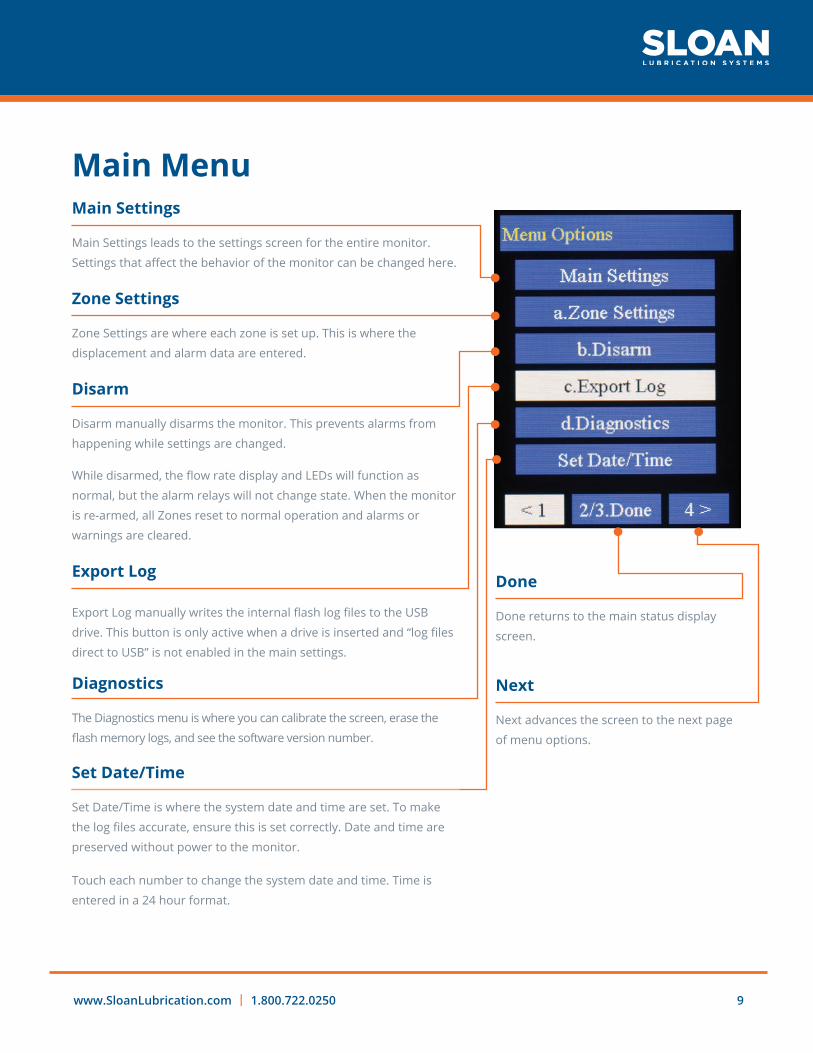
Main MenuMain Settings
Main Settings leads to the settings screen for the entire monitor.
Settings that affect the behavior of the monitor can be changed here.
Zone Settings
Zone Settings are where each zone is set up. This is where the
displacement and alarm data are entered.
Disarm
Disarm manually disarms the monitor. This prevents alarms from
happening while settings are changed.
While disarmed, the flow rate display and LEDs will function as
normal, but the alarm relays will not change state. When the monitor
is re-armed, all Zones reset to normal operation and alarms or
warnings are cleared.
Export Log
Export Log manually writes the internal flash log files to the USB
drive. This button is only active when a drive is inserted and “log files
direct to USB” is not enabled in the main settings.
Done
Done returns to the main status display
screen.
Next
Next advances the screen to the next page
of menu options.
Diagnostics
The Diagnostics menu is where you can calibrate the screen, erase the
flash memory logs, and see the software version number.
Set Date/Time
Set Date/Time is where the system date and time are set. To make
the log files accurate, ensure this is set correctly. Date and time are
preserved without power to the monitor.
Touch each number to change the system date and time. Time is
entered in a 24 hour format.

SLOAN LUBRICATION SYSTEMS10
Wizard Manual | Programming
Status Interval
Status Interval determines the rate at which the Monitor records
the current status of each zone to memory. 1 log entry per minute
generates ~200kB of data / day.
Disarm Max
Disarm Max indicates how long the disarm button will prevent an
alarm. The monitor starts in disarm mode, therefore this is also the
minimum amount of time an alarm can occur after power-up.
Startup Reset Cyc
Startup Reset Cyc sets how many cycles a warning will auto reset
upon startup or re-arm. This prevents startup glitches such as air in
the system or motors speeding up from displaying persistent
warnings. If the zone goes into alarm during this time, the alarm will
remain. This setting will only clear a zone in warning.
Log Split
Log Split determines the interval at which log new log files
are made.
TDS Also Resets Alarm
TDS Also Resets Alarm allows alarms to be reset with an external
switch. This is useful when the monitor is in a hazardous location and
the front panel cannot be accessed. To reset an alarm with the TDS
switch, hold the switch closed for at least 5 seconds.
Next
See next page.
Log Files Direct To USB
Log Files Direct to USB will write the log files directly to an attached
USB drive continuously as well as writing the logs to internal flash.
This prevents having to use the “export log” option on the main
menu and wait while log files are being written. The USB drive can
be removed at any time, but the log files will be written immediately
after the drive is reinserted.
Allow Remote Disarm
Allow Remote Disarm enables the remote
arm/disarm input on the back of the
monitor. These allow an external control
panel or switch to control the ability for the
Wizard to trip its alarm relays. If the monitor
is watching a system that frequently stops
and starts, this setting can be very useful to
prevent alarms when the equipment stops.
See page 23 for more information.
Main Settings

www.SloanLubrication.com | 1.800.722.0250 11
Unit Number and Unit Description
Unit Number and Unit Description are freeform text entry fields. The
information entered here is included with each log file and can be
useful to help identify where a log file originated.
Displacement Unit
Displacement Unit determines what units the displacement values in
the zone setup screens are in. This setting affects all zones. In most
divider block applications, this setting will be in3, but some
flow meter applications may require cm3.

SLOAN LUBRICATION SYSTEMS12
Wizard Manual | Programming
Check Boxes
Check boxes enable and disable each zone. When a zone is disabled,
all functionality is disabled. No flow rate will be displayed and alarm
relays will not change state.
If any settings are changed, each zone can be turned on or off
independently. Zones do not have to be enabled in any particular
order. For example, zones 2 and 4 may be enabled while 1 and 3
are disabled.
The text color next to each zone also represents that zone’s current
status.
See next page for details.
NOTEWhen setting up a zone, double check the values to make sure they are
correct. If a zone will not activate, the settings are likely in error somewhere.
Zone Configuration
The zone configuration data is entered here. This includes
displacement, alarm set point, description, and warning time.
If any data are changed while the unit is in operation, a reset is
performed on that zone when the settings are saved. This prevents
the monitor from immediately going into alarm if the low flow set
point is adjusted.
Zone Settings

www.SloanLubrication.com | 1.800.722.0250 13
Displacement
Displacement is the corresponding displacement of the divider block
or metering device that is connected to this zone input.
Low Flow Setpoint
Low Flow Setpoint is the flow rate below which warnings and alarms
will occur. This set point is selectable in many different units.
Volume Options
Volume options are pints, cm3, in3, gallons, and liters. Time options
available are seconds, minutes, hours, and days.
Zone Description
The Zone Description is a text label that is displayed on the main
screen. Maximum length is 9 characters.
Cancel
Cancel abandons any changes and returns to the main zone setup
screen.
Save
Save saves any changes and returns to the main zone setup screen.
Next
Push Next to see more options.
NOTEWhen editing values, use the backspace button on the screen
to clear the existing values before entering the new one.

SLOAN LUBRICATION SYSTEMS14
Wizard Manual | Programming
Zone Warning to Alarm
Zone Warning to Alarm is the number of cycles at the low flow
set point between warning and alarm. This is a buffer time in which
the monitor is in warning but has not sounded an alarm yet. The
time to which this setting is equivalent is displayed below the
number of cycles.
Zone Warning Reset
Zone Warning Reset is the number of cycles that must be seen ABOVE
the low flow set point while in alarm before automatically returning to
normal status. When a warning has happened, the status LED for that
zone stays lit yellow to notify an operator that a warning has occurred.
This does not apply on startup or after being armed for the number of
cycles defined by Startup Reset Cyc in the main settings.
Auto Zone Alarm Reset
Auto Zone Alarm Reset lets a zone return to normal operation after
the number of cycles specified by the Zone Warning Reset at a
measured rate higher than the Low Flow Setpoint.
Display Last 10 Avg
Display Last 10 Avg changes the zone display to show the moving
average flow rate of the last 10 cycles. This can be useful on systems
where the flow rate fluctuates.

www.SloanLubrication.com | 1.800.722.0250 15
Calibrate Screens
Calibrate Screen runs through a calibration routine for the touch
screen. This can be useful if the on-screen buttons are not working as
expected.
Update Software
Update Software is used to update the firmware of Wizard. See the
software update section of this document for more information.
Restart Unit
Restart Unit reboots the Wizard.
Clear Flash Logs
This function clears the on-board log file memory. It does not erase
the USB drive, so any logs already transferred to USB are saved.
CAUTION Rebooting the Wizard during operation may shut down equipment.
Diagnostics

SLOAN LUBRICATION SYSTEMS16
Wizard Manual | Programming
Load/Export
Load USB Settings loads a settings file from the USB drive. The file
must be renamed to sbcoSet.dat before the Wizard will load settings
from a file. Export settings saves the current Wizard settings to the
attached USB drive. This may be useful for copying settings from one
Wizard to other units. Contact Sloan for further information about
the settings file structure.
USB Status
This button indicates the status of the USB flash drive.
Current Software
The current software versions are useful when diagnosing a
problem. Have these numbers on-hand when contacting Sloan for
troubleshooting or techanical support.
Final Diagnostics Page
The final diagnostics page displays current network information.
Resetting the network connection will reconnect and re-obtain
DHCP information if enabled.

www.SloanLubrication.com | 1.800.722.0250 17
DHCP
When DHCP is enabled, the Wizard will attempt to automatically
obtain an IP address from a DHCP server on the network.
Manual Settings
Manual settings can be changed if DHCP is disabled.
When enabled, the current DHCP values (along with the units MAC
address) can be seen in the Diagnostics menu.
Remote Access
Pointing a web browser to the Wizard’s IP address will bring up a
remote interface for the unit. These are the username and password
to access the Web UI. It is recommended to change these to a site-
specific and secure value.
Disable the Web HMI to prevent remote access via web
browser entirely.
See page 21 for
more information.
Network Settings

SLOAN LUBRICATION SYSTEMS18
Wizard Monitor
The Wizard monitor supports Modbus communication via Modbus
RTU (RS485) or TCP/IP. Select the appropriate option.
RTU
When using RTU, select the proper settings for RS485 here. Slave ID is
the slave address at which the Wizard will respond to requests.
See the following page for Modbus Memory mapping information.
Modbus TCP
When using Modbus TCP, the port is changed here. Default port for
Modbus TCP is 502.
Troubleshooting
If having trouble interfacing with the Wizard where numbers are
not translating properly, the Byte order can be changed. This is also
known as endianness. Modbus Byte order is Big Endian by default,
but this may assist in interfacing with nonstandard equipment
or software.
Wizard Manual | Programming
Modbus Settings
www.SloanLubrication.com | 1.800.722.0250 19
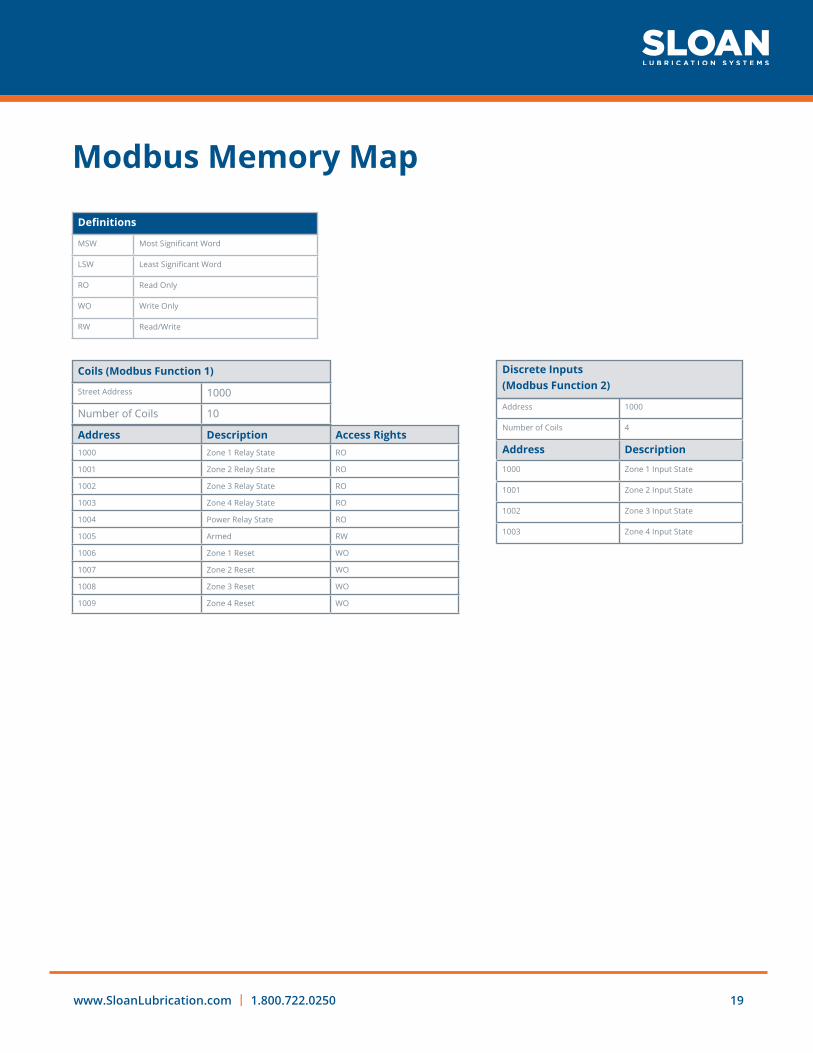
Modbus Memory Map
MSW Most Significant Word
LSW Least Significant Word
RO Read Only
WO Write Only
RW Read/Write
Street Address 1000
Number of Coils 10Address 1000
Number of Coils 4
Address Description
1000 Zone 1 Input State
1001 Zone 2 Input State
1002 Zone 3 Input State
1003 Zone 4 Input State
Address Description Access Rights1000 Zone 1 Relay State RO
1001 Zone 2 Relay State RO
1002 Zone 3 Relay State RO
1003 Zone 4 Relay State RO
1004 Power Relay State RO
1005 Armed RW
1006 Zone 1 Reset WO
1007 Zone 2 Reset WO
1008 Zone 3 Reset WO
1009 Zone 4 Reset WO
Coils (Modbus Function 1) Discrete Inputs (Modbus Function 2)
Definitions

SLOAN LUBRICATION SYSTEMS20
Modbus Memory Map
Wizard Manual | Programming
ValueFractionExponentValue Value
See this page for a more thorough description and explanation of special values (0, NaN, etc.):http://steve.hollasch.net/cgindex/coding/ieeefloat.html
Bit 31 Bit 30-23 Bits 22-00 10000010 10001011000011100000000
Sign Exponent Fraction
EEE 754 32-bit Floating Point Example:MSWLSWValueBias
= 0x4145= 0x8794= 0x41458794= 127
= 2Exponent * (1+Fraction)= [(Bit22 * 2-1) + (Bit21 * 2-2) + (Bit20 * 2-3) +…..+ (Bit0 * 2-23)]= Exponent - Bias = 130 - 127 = 3= 23 * (1.543200016021728515625)= 12.34560013
Address 1000
Number of Registers 36
Value Meaning
0 Zone Off
1 Zone Ok
2 Zone In Warning
3 Zone In Alarm
Input Registers
(Modbus Function 4)
Zone Status Key
Address Description Format Num Registers1000 Zone 1 flowrate FLOAT (IEEE 754 32-bit) 2
1001 (part of above value)
1002 Zone 2 flowrate FLOAT (IEEE 754 32-bit) 2
1003 (.. remainder removed)
1004 Zone 3 flowrate FLOAT (IEEE 754 32-bit) 2
1006 Zone 4 flowrate FLOAT (IEEE 754 32-bit) 2
1008 Zone 1 Total Flow FLOAT (IEEE 754 32-bit) 2
1010 Zone 2 Total Flow FLOAT (IEEE 754 32-bit) 2
1012 Zone 3 Total Flow FLOAT (IEEE 754 32-bit) 2
1014 Zone 4 Total Flow FLOAT (IEEE 754 32-bit) 2
1016 Zone 1 Low Point FLOAT (IEEE 754 32-bit) 2
1018 Zone 2 Low Point FLOAT (IEEE 754 32-bit) 2
1020 Zone 3 Low Point FLOAT (IEEE 754 32-bit) 2
1022 Zone 4 Low Point FLOAT (IEEE 754 32-bit) 2
1024 Zone 1 Displacement FLOAT (IEEE 754 32-bit) 2
1026 Zone 2 Displacement FLOAT (IEEE 754 32-bit) 2
1028 Zone 3 Displacement FLOAT (IEEE 754 32-bit) 2
1030 Zone 4 Displacement FLOAT (IEEE 754 32-bit) 2
1032 Zone 1 Status Decimal 1
1033 Zone 2 Status Decimal 1
1034 Zone 3 Status Decimal 1
1035 Zone 4 Status Decimal 1
Binary
Function

www.SloanLubrication.com | 1.800.722.0250 21
The Wizard monitor includes a built in web server for remote
access. To access the web HMI, point a web browser to the IP
address of the Wizard. To gain access, a user needs to enter
the username and password specified in the Network Settings
menu on the unit.
In the web HMI, status of various zones can be accessedas
well as some settings. Crucial settings such as zone
displacement and low flow set point can only be entered via
the front panel of the Wizard itself.
The pages are laid out in a similar fashion to the screens on
the unit itself, so refer to the previous sections of this manual
for explanation.
NOTE:
Be certain to set a site-specific password for the web access
functionality. If it will not be used, Sloan recommends that
the feature be disabled via the front panel to limit potential
security risk.
Web Based Remote HMI

SLOAN LUBRICATION SYSTEMS22
Wizard Manual | Menu Map
Menu Map

www.SloanLubrication.com | 1.800.722.0250 23

SLOAN LUBRICATION SYSTEMS24
Wizard Manual | Operation
During normal operation, the primary status display is shown. The
status of each zone is reflected in the color of the flow rate number
as well as the LED color above the display. The LEDs will also flash
blue to indicate that the attached proximity switches are functioning.
If a zone is disabled, the LED for that zone is also disabled.
If the flow rate for a zone falls below the programmed set point, the
zone enters warning. From there, if the flow rate continues to fall
below that set point for the number of cycles in the Zone Warning to
Alarm setting, the zone will go into alarm and the alarm relay will trip.
If the flow rate climbs back above the set point and Auto Zone Alarm
Reset is enabled for that zone, it will go back into warning mode and
then back into normal mode.
When a warning has occurred on a zone, but normal operation
continued, the LED for that zone will remain yellow to notify the
operator that a warning had occurred. The date and time of the last
warning for a zone can be seen on the second Zone Breakdown
screen. The exception to this rule is during start-up when a value
is entered into the Startup Reset Cyc setting. In this case, the LED
will return to green if a warning is encountered during the specified
number of cycles. This can be useful on larger systems or where it
may take some time for the system to stabilize. Alarms will still occur
during this time, so the lubricated equipment is still protected.
The power failure relay also can be used in series with any of the
other relays or separately to indicate a failure of power to the
monitor. The relay energizes when power is applied to the Wizard
and will de-energize when power is removed.
Zone Status LEDs indicating a failure on zone 2. Zones 1 and 3 are normal. Zone 4 is disabled.
Zone Status LEDs indicating a single enabled zone in warning.
Operation

www.SloanLubrication.com | 1.800.722.0250 25
In most installations, the Wizard monitor is mounted in an enclosure with a switch on the side, typically labeled TDS (Total Display Switch).
This switch is wired to the TDS contacts on the back of the wizard and
performs several functions. It allows an operator to see the total flow on a
zone since the last TDS reset was performed as well as reset warnings and
alarms. This functionality is particularly useful in hazardous locations where
the enclosure cannot be opened during normal day-to-day activities. In this
case, the switch is probably an aluminum plug with a magnet hanging nearby.
Touching the plug with the magnet activates the switch.
TDS operations are as follows:
• Touch (<5 seconds) to change between flow rate and total displays.
• Hold (>5 seconds and <10 seconds) to reset alarms on all zones. (This only applies if the TDS Also Resets Alarms check box is checked.)
• Hold (>10 seconds) to reset the total value.
TDS (Total Display Switch)

SLOAN LUBRICATION SYSTEMS26
Wizard Manual | Operation
Example #1 – Simple Or Legacy Style Connections
In this example, the Wizard is monitoring the flow rates on a GMVA-8-3 integral engine/
compressr with 8 power cylinders and 4 compressor cylinders. There are 2 lubrication zones,
1 to the compressor cylinders at 4.5 pints / day and 1 to the power cylinders at 24.0 pints / day.
System layout is as shown.
8 RPM Input
Lubricator Box
Supply Shutoff & C/V
CrankcaseSupply
Inlet Filter Assembly
CompressorGauge
PowerGauge
CompressorPrimary
PowerPrimary
CompressorSecondary x3
PowerSecondary x2
Compressor Secondary
Details
0.3 PPD, Cyl.0.3 PPD, Cyl. 6T
6S
3S
0.6 PPD, Pkg.0.3 PPD, Cyl.
Divider Assembly Details:16 feeds to power for 24.0 pints/dayPower primary cycle time is 18.0 seconds.144 cubic inches delivered to secondaries per cycle
12 feeds to compressor for 4.5 pints/dayCompressor primary cycle time is 24.0 seconds.030 cubic inches delivered to secondaries per cycle
Usage Examples

www.SloanLubrication.com | 1.800.722.0250 27
For this application, the Wizard would be set as follows:
Main settings: Status interval is 5 (for 5 minute log intervals), disarm max is
60, and startup reset cycles is 10 (this unit is air started and takes a while to
get up to speed). The unit number is 2, and “station 21 gmva-8-3” will go in the
description so that the log files can be identified easily.
Zone 1 displacement is 0.030 in^3 and the alarm is set to 2.3 pints/day.
This zone is labeled “comp.”
Zone 2 displacement is 0.072 in^3 and the alarm is set to 12 pints / day.
This zone is labeled “pwr”.
Zones 3 and 4 are disabled.
Wire the Wizard according to the diagram below.
The wizard will have power applied when the compressor starts.
The legacy alarm circuit (normally closed) is wired into the Z1, Z2,
and Power fail relays.

SLOAN LUBRICATION SYSTEMS28
Wizard Manual | Operation
Example #2 – PLC Integrated Installation
In this example, the Wizard is monitoring the flow rates on an Ariel JGC/4 operating
in a refinery gas recycle process. It has two stages with 9.626” and 6.75” cylinders
and 6.5” stoke. It is electrically driven, running @ 1000 RPM. There are two
lubrication zones, one to each stage. Zone 1 is the 1st (LP) stage and requires 3.9
pints/day. Zone 2 is the 2nd (HP) stage and requires 3.0 pints/day. The pumps are
electrically driven and the oil is supplied from a daytank. The Wizard will be integrated
into the skid PLC control system using Modbus TCP/IP.
System layout is as shown.

www.SloanLubrication.com | 1.800.722.0250 29
For this application, the Wizard would be set as follows:
Main settings: Status interval is 1 (for 1 minute log
intervals), disarm max is 60, and startup reset cycles is 5.
The unit number is 1 and “C-301 recycle a” will go in the
description so that the log files can be identified easily.
Zone 1 displacement is 0.036 in^3 and the alarm is set
to 2.5 pints/day. This zone will be labeled “hp cyl”. Zone
warning to alarm is set at 4 cycles, and warning reset
is 2 cycles.
Zone 2 displacement is 0.036 in^3 and the alarm is set
to 2.0 pints / day. We will label this zone “lp cyl”. Zone
warning to alarm is set at 4 cycles, and warning reset
is 2 cycles.
Zones 3 and 4 are disabled.
In Network Settings, the network is set to DHCP as the
plant DHCP server will be assigning IP addresses. The web
HMI is enabled. Modbus is set to TCP with the default port
of 502. Bit format is the default ABCD.
The Wizard is wired according to the diagram to the right.
The Wizard will always have power applied when the
control panel is powered.
The PLC is polling the Wizard at 250ms intervals. If
the wizard does not respond for 5000ms, an operator
notification is sent. If no response after 2 minutes, the
compressor is shut down for communication error. If
a Zone status remains 3 (decimal) for 30 seconds, the
compressor is shut down on “no flow.”
24V DCPower
LP Divider HP Divider Tank Low Level Switch
The PLC is interfacing with the following registers via Modbus TCP/IP:
Function 1 (read coil) Address 1005 (Arm/disarm status)
Function 5 (Write single coil) Addresses 1005 (arm/
disarm set), 1006 (Reset Zone 1), 1007 (Reset Zone 2)
Function 2 (Read inputs) Addresses 1000 (Zone 1 switch),
1001 (Zone 2 switch), 1003 (Zone 4 switch, tank Low level)
Function 4 (Read input registers) Addresses 1000&1001
(Zone 1 flow rate), 1002&1003 (Zone 2 flow rate), 1032
(Zone 1 status), 1033 (Zone 2 status)

SLOAN LUBRICATION SYSTEMS30
Wizard Manual | Operation
Wizard will not power on
Ensure that the power source is connected to the proper input. The Wizard
has connections for both AC and DC power supplies.
If connected, make sure the input voltage and current at the Wizard plug are
within the proper operating range.
Zone input does not appear to be working
Check prox switch wiring. Ensure that external voltage is not applied
to the input.
Double check that the input is functioning by watching a small green LED
on the I/O circuit board directly next to the input plug. This can be useful
for troubleshooting purposes as a lit LED indicates a closed circuit.
Make sure the corresponding zone is enabled (zone status LED on the front
panel will be lit) and has valid settings. Required settings are Displacement
and Low Flow Setpoint.
When a zone registers a cycle from the input, the zone status LED
will flash blue.
Wizard will not display a flow rate
Verify that Wizard is properly registering input cycles (zone status LED is
flashing blue once every cycle).
Manually run pump or cycle prox switch by hand to simulate flow.
Check zone settings to make sure they have correct values. The block
displacement and low flow setpoint must have values.
*
Troubleshooting

www.SloanLubrication.com | 1.800.722.0250 31
Displayed flow rate does not match what I expected
Double check block displacement. Ensure that the displacement units
are correct (either In^3 or Cm^3) for the monitored block in the main
settings screen.
Verify that wiring connections between the prox switch and Wizard are good
and there are no loose wires.
Alarms do not appear to be working as expected
Verify zone settings.
Make sure warning to alarm values are set.
Ensure that unit is not disarmed and that “remote arm/disarm” functionality is
properly selected in the main settings screen.
Double check that the output is functioning by watching a small green LED on
the I/O circuit board directly next to the output relay plug. This can be useful
for troubleshooting purposes as a lit LED indicates an energized relay.
Wizard indicates that it is “disarmed” and will not arm
Verify proper selection of the “remote arm/disarm” functionality in the main
settings sreeen.
Make sure the remote arm/disarm wires are properly connected. Like the
zone inputs, this is a dry contact circuit and should not have external
voltage applied.

SLOAN LUBRICATION SYSTEMS32
Wizard Manual | Operation
Modbus (RS485) is not working
Make sure wiring is correct.
Double check that RTU is selected in the Modbus settings screen.
Double check slave unit number and serial port settings. Port settings must
match all other devices on the network and unit number must be unique.
Start with a single register (like zone 1 input) and verify that it is fully functional
before adding the rest.
Some systems may offset their registers by 1; therefore the PLC register “1000”
may actually be 999, or 1001. Some trial and error may be required to figure
out the offset.
Modbus TCP/IP is not working
Make sure wiring is properly connected. Double check proper termination of
any plugs on the network cable.
Check switch and Wizard plug for link lights. If there are no link lights, there is
a wiring issue.
Double check network settings. If DHCP is being used, double check that
Wizard is receiving a valid IP address.
Make sure TCP is selected on the Modbus settings page and that the proper
port number is entered.
If network settings are correct, try loading the remote HMI site by pointing a
web browser at the Wizards IP address. If that is working, networking is OK
and the issue is specific to Modbus.
Try steps in the next troubleshooting section.

www.SloanLubrication.com | 1.800.722.0250 33
Modbus is working, but the values do not match what is expected
Some systems may offset their registers by 1. So the PLC register “1000” may
actually be 999, or 1001. Some trial and error may be required to figure out
the offset is.
Start with a single register (like zone 1 input) and verify that it is fully functional
before adding the rest.
Remote HMI web server is not working
Try the first 5 steps under “Modbus TCP/IP is not working” first.
Double check that the Remote HMI is enabled in the 3rd page ofNetwork
Settings.
Double check the username and password are correct and match those
entered in the Network Settings screen.
For any other issues, contact Sloan at any time! See contact information on page 37.

SLOAN LUBRICATION SYSTEMS34
Wizard Manual | Data Logging
Data logging on the Wizard is continuous and cannot be disabled. The USB
drive can be removed or inserted at any time except when the screen displays
“Writing files to USB…”
When Log Files Direct to USB is enabled in the main settings menu, the log files
are continuously written and are always up-to-date. A second copy of the logs
is also held in main memory and is updated even while the USB drive is not
attached. Re-inserting the drive or inserting a new blank drive will immediately
re-write all the logs in internal memory. This is the recommended setting as
the USB drive always has the most current copy of the log files. The log files are
also accessible when the monitor does not have power or has been disabled in
some way.
If Log Files Direct to USB is not enabled, logs must be manually written to
the USB drive using the Export Log button in the main menu. Note that if the
Wizard has been in operation for some time with the Status Interval (min) value
set to a low number, the log files may be substantial in size and take a long time
to generate and write to USB. During this time, the lubricated equipment is still
protected, but the Wizard cannot be used for anything else and will not display
current flow data. For this reason alone, we recommend that the log files are
always logged directly to USB as well as stored in main memory.
There are two types of log files written by the Wizard. One begins with an S and
other begins with an E. Both log files are split up by day, with the date of the log
(YYMMDD) as the file name.
The “E” logs record any changes made to the Wizard along with any alarms or
other zone status changes. Each entry has a date and time stamp along with
information as to why the entry was recorded.
Data Logging

www.SloanLubrication.com | 1.800.722.0250 35
The “S” logs are a record of the status of the Wizard Monitor at regular intervals.
This interval is determined by the Status Interval (min) setting. Setting this value
to 1 records a new status entry once a minute and generates approximately
200kB of data per day. Each log entry is a snapshot of the Wizard at that time
and includes the current flow rate, status, and alarm condition of each zone as
well as the status of the alarm relays and temperature of the monitor.
The Wizard Monitor can store at least 2 years of log data internally with the
log interval set to 1 minute. Once the internal memory is full, the monitor will
start to overwrite the oldest data first. This also applies to the USB drive. The
included USB drive should be sufficient to contain 5 years of log data.
In order to keep the time required to write the log files to USB to a
minimum, we recommend that users back up the files from and clear the USB
drive once a year. Also delete the internal flash logs on the Wizard itself at this
time. This function can be found in the Diagnostic menu.

SLOAN LUBRICATION SYSTEMS36
Wizard Manual | Software Updates
Occasionally, Sloan will post software updates to the Wizard Monitor on our
website – www.sbco.com. Each update will include the required files as well as
a list of changes or fixes made by the update. In most cases, the update will
not affect the underlying functionality of the monitor, but will fix minor bugs or
visual glitches.
CAUTIONPrior to performing a software update, ensure that the monitor is not currently protecting any piece of equipment! During the process, the alarm relays will change state.
The following procedure applies to Wizard monitors shipped before 05/01/2015 and with serial numbers below 15-D00001.
NOTE: This update procedure will delete existing data logs from the Wizard.
Back up your current logs if you wish to retain this data.
• Put all update files onto a USB Stick and insert the USB stick into the port
on the Wizard.
• Hold the buttons 1 & 3 & A & C down together until the top row of LEDs
turns green and the screen goes blank. This takes 5 seconds. Release the
buttons and the first update procedure will run. This takes between 30
and 60 seconds.
• Once the monitor has rebooted, go into Menu->Diagnostics->Page 2 and
select “Update Software”
• The complete software update procedure will now run. This
process takes between 90 seconds and 2 minutes.
• Your Monitor is now all up-to-date! From this point forward, the software
on this monitor can be updated using the “Update Software” menu item on
the second diagnostics screen.
Software Updates

www.SloanLubrication.com | 1.800.722.0250 37
Thank you for using the Wizard Monitor! If you have any additional questions, call us at any time at 1-800-722-0250.
After hours, leave a message and someone will be in touch shortly.
We are also available via email at [email protected] or you can contact any
of us personally on our cell phones or via email:
C.J. Sloan
Matt McCarthy
Brian Sloan
Eric Sloan
For Wizard Monitors shipped after 05/01/2015 and with Serial numbers above 15-D00001 OR units that have had a software version starting with 4 Installed, follow the following procedure.
• Put all update files onto a USB stick and insert the USB stick into
the port on the Wizard.
• Navigate to the diagnostics menu and select item b. “Update
Software”.
• Select Yes to perform the update.
412-491-2308 [email protected]
412-400-7985 [email protected]
412-400-2775 [email protected]
412-400-7987 [email protected]
Contact Information

168 Armstrong Drive, Freeport, PA 16229 | 1.800.722.0250 | www.SloanLubrication.com
Wizard Manual