wölfer moves the world wölfer bewegt die welt · bow thruster motor 700kw s2-30 min,1790rpm...
TRANSCRIPT

Wölfer moves the world Wölfer bewegt die Welt
Marine applicationSchiffsausführungThree phases low voltage squirrel cage and slip ring motors Drehstrom-Käfigläufer- / Schleifringläufer-Motoren
Catalog S12.4Katalog S12.4

INDEX OF CONTENTSINHALTSVERZEICHNIS
Franz Josef Hemesath · Managing DirectorFranz Josef Hemesath · Geschäftsführer
1. Introduction 1.1 Company profile 1.2 Qualitymanagement
2.Generaltechnicalinformation 2.1 Standards and regulations 2.2 Product code 2.3 Types of construction 2.4 Electrical design 2.5 Mechanical design 2.6 More components 2.6.1 Methods of cooling EN 60034-6 2.6.2 Forced cooling fans 2.6.3 Brakes 2.6.4 Encoders
3.Motordata 3.1 Squirrel cage motors 4 pole – IC 411 – 50 Hz
4 pole – IC 411 – 60 Hz 6 pole – IC 411 – 50 Hz 6 pole – IC 411 – 60 Hz 4 pole – IC 410 – 50 Hz 4 pole – IC 410 – 60 Hz 4 pole – IC 01 – 50 Hz 4 pole – IC 01 – 60 Hz 6 pole – IC 01 – 50 Hz 6 pole – IC 01 – 60 Hz
3.2 Slip ring motors 4 pole – IC 01 – 50 Hz
4 pole – IC 01 – 60 Hz 6 pole – IC 01 – 50 Hz 6 pole – IC 01 – 60 Hz
4.Dimensionaldrawings 4.1 Squirrel cage motors MDK – IC 411 – IM V1
MDK – IC 411 – IM V1 MDKO – IC 410 – IM V1 MDKO – IC 410 – IM V1 MODK – IC 01 – IM V1 MODK – IC 01 – IM V1
4.2 Slip ring motors MSODK – IC 01 – IM V1 5.Contact 5.1 Contact persons 5.2 Directions
1. Einleitung 1.1 Unternehmensprofil 1.2 Qualitätsmanagement
2.TechnischeErläuterungen 2.1 Normen und Vorschriften 2.2 Typenbezeichnungen 2.3 Bauformen 2.4 Elektrische Ausführung 2.5 Mechanische Ausführung 2.6 Weitere Komponenten 2.6.1 Kühlverfahren nach EN 60034-6 2.6.2 Fremdlüfter 2.6.3 Bremsen 2.6.3 Encoder
3.Leistungstabellen 3.1 Käfigläufer-Motoren 4-polig – IC 411 – 50 Hz
4-polig – IC 411 – 60 Hz 6-polig – IC 411 – 50 Hz 6-polig – IC 411 – 60 Hz 4-polig – IC 410 – 50 Hz 4-polig – IC 410 – 60 Hz 4-polig – IC 01 – 50 Hz 4-polig – IC 01 – 60 Hz 6-polig – IC 01 – 50 Hz 6-polig – IC 01 – 60 Hz
3.2 Schleifringläufer-Motoren 4-polig – IC 01 – 50 Hz
4-polig – IC 01 – 60 Hz 6-polig – IC 01 – 50 Hz 6-polig – IC 01 – 60 Hz
4.Maßblätter 4.1 Käfigläufer-Motoren MDK – IC 411 – IM V1
MDK – IC 411 – IM V1 MDKO – IC 410 – IM V1 MDKO – IC 410 – IM V1 MODK – IC 01 – IM V1 MODK – IC 01 – IM V1
4.2 Schleifringläufer-Motoren MSODK – IC 01 – IM V1
5.Kontakt 5.1 Ansprechpartner 5.2 Anfahrtsskizze
67
101112-131415-17181819-202121
24252627282930313233
34353738
404142434445
46
4950-51
welcome to the Franz Wölfer Elektromaschinenfa brik. The catalogue at hand gives an overview on the deliv-erable eletric motors in and upon ships.
Additionally to the listed standard possibilities, we can offer you individually produced electric motors according to your wishes and exigencies. Due to the manifold enhancement and specialisation possibil-ities, there are almost no technical limits in the matter of motor configuration. You will find the construction for your application in our large assortment. Please contact us, we will also be glad to establish an individual solution for you.
When you should search motors for further applica-tions, please feel free to ask our friendly contact persons.
herzlich willkommen bei der Franz Wölfer Elektroma-schinenfabrik. In dem vorliegenden Katalog finden Sie eine Übersicht über unsere lieferbaren Motoren für den Einsatz in und auf Schiffen.
Zusätzlich zu den aufgelisteten Standardlösungen bieten wir Ihnen individuell nach Ihren Wünschen und Anforderungen gefertigte Motoren für höchste An-sprüche. Aufgrund unserer vielen Erweiterungs- und Spezialisierungsmöglichkeiten sind Ihnen in Sachen Motorengestaltung kaum Grenzen gesetzt. In un-serem umfangreichen Sortiment finden Sie die für Ih-ren Einsatzzweck benötigte Ausführung. Nehmen Sie Kontakt zu uns auf, wir erstellen gerne auch individu-elle Lösungen für Sie.
Sollten Sie Motoren für weitere Einsatzzwecke suchen, fragen Sie unsere freundlichen Ansprechpartner nach entsprechenden Produktkatalogen.
Dear customers, dear interested persons,Sehr geehrte Kunden, sehr geehrte Interessierte,
Three phases low voltage squirrel cage and slip ring motors for marine applicationDrehstrom-Käfigläufer- / Schleifringläufer-Motoren in Schiffsausführung
Catalog S12.4Katalog S12.4
Three phases low voltage squirrel cage and slip ring motors for marine applicationDrehstrom-Käfigläufer- / Schleifringläufer-Motoren in Schiffsausführung
Catalog S12.4Katalog S12.4

Bowthrustermotor700kWS2-30min,1790rpmBugstrahlruderantriebsmotor700kWS2-30min,1790rpm
INTRODUCTIONEINLEITUNG

Three phases low voltage squirrel cage and slip ring motors for marine applicationDrehstrom-Käfigläufer- / Schleifringläufer-Motoren in Schiffsausführung
Catalog S12.4Katalog S12.4
Three phases low voltage squirrel cage and slip ring motors for marine applicationDrehstrom-Käfigläufer- / Schleifringläufer-Motoren in Schiffsausführung
Catalog S12.4Katalog S12.4
1. Introduction1. Einleitung
1. Introduction1. Einleitung
1.2 Quality management
Since april 2008, the Franz Wölfer Elektromaschinenfabrik has been TÜV certified according to DIN EN ISO 9001:2000. The am-bit for this certificate for quality assurance and process enhance-ment ranges over the areas “development, production, and dis-tribution of electric motors and drives”.
1.2 Qualitätsmanagement
Seit April 2008 ist die Franz Wölfer Elektromaschinenfabrik nach DIN EN ISO 9001:2000 vom TÜV Nord zertifiziert. Der Geltungs-bereich des Zertifikats für Qualitätssicherung und Prozessopti-mierung erstreckt sich über die Bereiche „Entwicklung, Herstel-lung und Vertrieb von Elektromotoren und Antrieben“.
1.1 Company profile
For over 60 years now Franz Wölfer Elektromaschinenfabrik has been developing and manufacturing smooth-running electric motors for use in hoisting equipment, in and on ships as well as in general mechanical engineering. We apply our extensive know-how to produce highly efficient motors for individually adapted drive mechanism solutions. At our business location in Osnabrück our employees work hard to ensure highest quality standards. Customers throughout the world are convinced by the performance capacity, compactness, dynamics and high degree of efficiency of our innovative prod-ucts. In the manufacture of hoist motors we are indeed one of the leading companies concerning quality as well as techno- logy. We produce electric motors with a performance up to 2.000 kW.
Our high-capacity motors are still produced exclusively at our business location in Osnabrück - Sutthausen. We are constant-ly expanding this location and modernising the production tech-nology. In 2007 we acquired a testing station, which is one of the most modern and efficient systems for testing electric motors in Northern Germany. In 2008, the ground-breaking ceremony for our new production building.
1.1 Unternehmensprofil
Seit über 60 Jahren entwickelt und fertigt die Franz Wölfer Elek-tromaschinenfabrik laufsichere Elektromotoren für die Verwen-dung in der Hebezeugtechnik, in und auf Schiffen und im allge-meinen Maschinenbau. Mit umfangreichem Know-how erstellen wir hocheffiziente Motoren für individuell angepasste Antriebslö-sungen. Am Unternehmensstandort in Osnabrück sichern unsere Mitarbeiter höchste Qualitätsstandards. Weltweit sind Kunden von der Leistungsstärke, Kompaktheit, Dynamik und dem hohen Wirkungsgrad unserer innovativen Produkte überzeugt. In der Herstellung von Motoren für die Hebezeugtechnik sind wir einer der Qualitäts- und Technologieführer. Wir produzieren Elektro-motoren mit einer Leistung bis zu 2.000 kW.
Die Fertigung unserer leistungsfähigen Motoren erfolgt aus-schließlich in Osnabrück-Sutthausen. Kontinuierlich bauen wir unseren Unternehmensstandort aus und modernisieren die ver-wendete Produktionstechnologie. 2007 wurde eine Prüfanlage erworben. Es handelt sich um die modernste und leistungsstärks-te Anlage zum Testen von Elektromotoren in Norddeutschland. 2008 erfolgte der Spatenstich für unser neues Produktions- und Werksgebäude.
6 7

GENERAL TECHNICAL INFORMATIONTECHNISCHE ERLÄUTERUNGEN
Three phases low voltage squirrel cage and slip ring motors for marine applicationDrehstrom-Käfigläufer- / Schleifringläufer-Motoren in Schiffsausführung
Catalog S12.4Katalog S12.4
Three phases low voltage squirrel cage and slip ring motors for marine applicationDrehstrom-Käfigläufer- / Schleifringläufer-Motoren in Schiffsausführung
Catalog S12.4Katalog S12.4
2.1 Standards and regulations
This list contains motors which are specially designed for ships. The motor windings are made by means of a special insulation which is suitable for frequency inverter operation due to its resis-tance against high voltages. High speeds within the range of field-weakening are possible due to the high breakdown torques of the motors (crane systems on ships). This is achieved by the use of a specially designed rotor, which had been developed for frequency inverter drives.
The dial frequency (the point on which the motor torque de creases and the power remains constant) of the motors described in this catalogue is taken with 50 Hz rather 60 Hz. Oth-er dial frequencies are possible, but require other types of wind-ings.
Here after, there is a summary of the different classification com-panies where by the motors can be tested. If specially desired, the motors can also be tested by other classification companies.
2.1 Normen und Vorschriften
Diese Liste enthält Sondermotoren, die speziell für Schiffe konzi-piert worden sind. Sollten die Motoren für den Frequenzumrich-terbetrieb ausgelegt werden, so sind die Wicklungen mit einer Spezialisolierung gefertigt, die aufgrund ihrer Spannungsfestig-keit hierfür geeignet ist. Auch sind relativ hohe Drehzahlen im Feldschwächbereich durch hohe Motor-Kippmomente zu erzie-len (Krananlagen auf Schiffen). Dies wird durch einen Sonderro-tor erreicht, dessen Geometrie speziell für Frequenzumrichteran-triebe entwickelt worden ist.
Die Eckfrequenz (der Punkt, ab dem sich das Drehmoment verringert und die Leistung konstant bleibt) dieser Motoren ist in den Leistungsblättern mit 50 Hz bzw. 60 Hz angenommen. Andere Eck frequenzen sind möglich, erfordern allerdings eine andere Wicklungsauslegung.
Nachstehend ist eine Zusammenfassung der verschiedenen Klassifikationsgesellschaften aufgeführt, wonach die Motoren geprüft werden können. Auf besonderen Wunsch können die Motoren auch nach anderen Klassifikationsvorschriften geprüft werden.
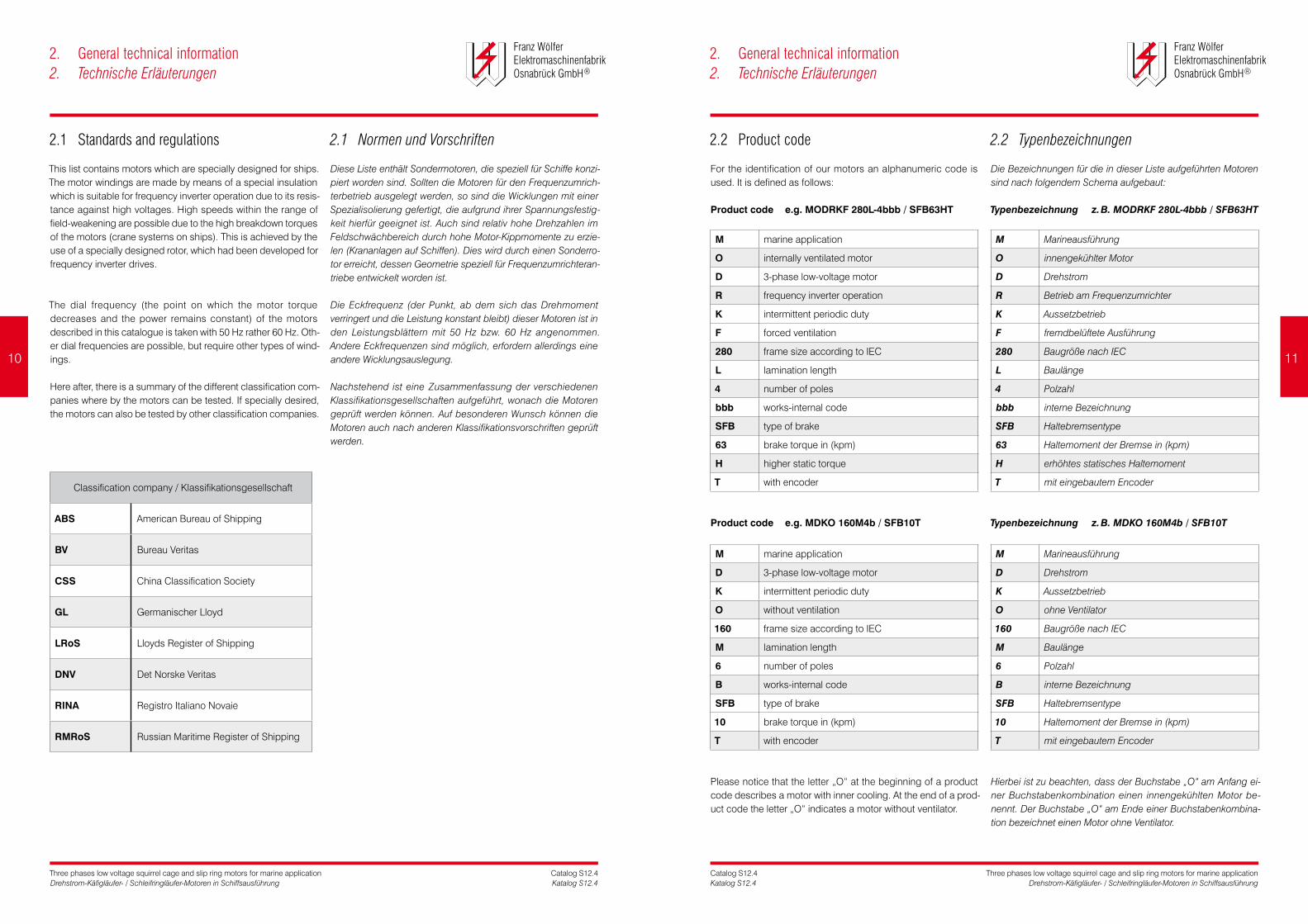
2.2 Product code
For the identification of our motors an alphanumeric code is used. It is defined as follows:
Product code e.g. MODRKF 280L-4bbb / SFB63HT
M marine application
O internally ventilated motor
D 3-phase low-voltage motor
R frequency inverter operation
K intermittent periodic duty
F forced ventilation
280 frame size according to IEC
L lamination length
4 number of poles
bbb works-internal code
SFB type of brake
63 brake torque in (kpm)
H higher static torque
T with encoder
Product code e.g. MDKO 160M4b / SFB10T
M marine application
D 3-phase low-voltage motor
K intermittent periodic duty
O without ventilation
160 frame size according to IEC
M lamination length
6 number of poles
B works-internal code
SFB type of brake
10 brake torque in (kpm)
T with encoder
Please notice that the letter „O“ at the beginning of a product code describes a motor with inner cooling. At the end of a prod-uct code the letter „O“ indicates a motor without ventilator.
2.2 Typenbezeichnungen
Die Bezeichnungen für die in dieser Liste aufgeführten Motoren sind nach folgendem Schema aufgebaut:
Typenbezeichnung z.B.MODRKF280L-4bbb/SFB63HT
M Marineausführung
O innengekühlter Motor
D Drehstrom
R Betrieb am Frequenzumrichter
K Aussetzbetrieb
F fremdbelüftete Ausführung
280 Baugröße nach IEC
L Baulänge
4 Polzahl
bbb interne Bezeichnung
SFB Haltebremsentype
63 Haltemoment der Bremse in (kpm)
H erhöhtes statisches Haltemoment
T mit eingebautem Encoder
Typenbezeichnung z.B.MDKO160M4b/SFB10T
M Marineausführung
D Drehstrom
K Aussetzbetrieb
O ohne Ventilator
160 Baugröße nach IEC
M Baulänge
6 Polzahl
B interne Bezeichnung
SFB Haltebremsentype
10 Haltemoment der Bremse in (kpm)
T mit eingebautem Encoder
Hierbei ist zu beachten, dass der Buchstabe „O“ am Anfang ei-ner Buchstabenkombination einen innengekühlten Motor be-nennt. Der Buchstabe „O“ am Ende einer Buchstabenkombina-tion bezeichnet einen Motor ohne Ventilator.
2. General technical information2. Technische Erläuterungen
2. General technical information2. Technische Erläuterungen
Classification company / Klassifikationsgesellschaft
ABS American Bureau of Shipping
BV Bureau Veritas
CSS China Classification Society
GL Germanischer Lloyd
LRoS Lloyds Register of Shipping
DNV Det Norske Veritas
RINA Registro Italiano Novaie
RMRoS Russian Maritime Register of Shipping
10 11

Three phases low voltage squirrel cage and slip ring motors for marine applicationDrehstrom-Käfigläufer- / Schleifringläufer-Motoren in Schiffsausführung
Catalog S12.4Katalog S12.4
Three phases low voltage squirrel cage and slip ring motors for marine applicationDrehstrom-Käfigläufer- / Schleifringläufer-Motoren in Schiffsausführung
Catalog S12.4Katalog S12.4
2.3 Types of construction
Types of construction of rotating electrical machines are desig-nated in accordance with EN 60034-7 Code I and Code II.The table below shows the most common types of con struction.
If required, other types of construction are available.
Motors with end shields, horizontal mounting
2.3 Bauformen
Die Bauformen für umlaufende elektrische Maschinen sind nach EN 60034-7, Code I und Code II bezeichnet.Nachstehende Tabelle zeigt die für Normmotoren gebräuch-lichsten Bauformen.
Auf Wunsch sind auch andere Bauformen lieferbar.
MotorenmitLagerschilden,horizontalerAnbau
2.3 Types of construction
Types of construction of rotating electrical machines are desig-nated in accordance with EN 60034-7 Code I and Code II.The table below shows the most common types of cons truction.
If required, other types of construction are available.
Motors with end shields, vertical mounting
2.3 Bauformen
Die Bauformen für umlaufende elektrische Maschinen sind nach EN 60034-7, Code I und Code II bezeichnet.Nachstehende Tabelle zeigt die für Normmotoren gebräuch-lichsten Bauformen.
Auf Wunsch sind auch andere Bauformen lieferbar.
MotorenmitLagerschilden,vertikalerAnbau
2. General technical information2. Technische Erläuterungen
2. General technical information2. Technische Erläuterungen
Code I Code II Description Beschreibung
IM B3 IM 1001
2 end shields, with feetfree shaft extensionmounting on existing base
2 Lagerschilde, mit Füßen freies Wellenende Aufstellung auf Unterbau
IM B35 IM 2001
2 end shields, with feetfree shaft extensionmounting flange type A at DE mounting on base for flange
2 Lagerschilde mit Füßenfreies WellenendeFlansch Form A auf ASAufstellung auf Flansch-unterbau
IM B5 IM 3001
2 end shields, without feetfree shaft extensionmounting flange type A at DEflange mounting
2 Lagerschilde, ohne Füßefreies WellenendeFlansch Form A auf ASFlanschanbau
IM B6 IM 1051
2 end shields, with feetfree shaft extensionwall-mountingfeet LH seen from DE
2 Lagerschilde, mit Füßenfreies WellenendeBefestigung an der WandFüße von AS gesehen links
IM B7 IM 1061
2 end shields, with feetfree shaft extensionwall-mountingfeet RH seen from DE
2 Lagerschilde, mit Füßenfreies WellenendeBefestigung an der WandFüße von AS gesehen rechts
IM B8 IM 1071
2 end shields, with feetfree shaft extensionceiling-mounting
2 Lagerschilde, mit Füßenfreies WellenendeBefestigung an der Decke
Code I Code II Description Beschreibung
IM V1 IM 3011
2 end shields, without feetfree shaft extensionmounting flange type A at DEbottom flange-mounting
2 Lagerschilde, ohne Füßefreies Wellenende untenFlansch Form A auf ASFlanschanbau unten
IM V3 IM 3031
2 end shields, without feetfree shaft extensionmounting flange type A at DEoverhead flange-mounting
2 Lagerschilde, ohne Füßefreies Wellenende obenFlansch Form A auf ASFlanschanbau oben
IM V5 IM 1011
2 end shields, with feetfree shaft extension pointingdownwardswall-mounting
2 Lagerschilde, mit Füßenfreies Wellenende untenBefestigung an der Wand
IM V6 IM 1031
2 end shields, with feetfree shaft extension pointingupwardswall-mounting
2 Lagerschilde, mit Füßenfreies Wellenende obenBefestigung an der Wand
12 13

Three phases low voltage squirrel cage and slip ring motors for marine applicationDrehstrom-Käfigläufer- / Schleifringläufer-Motoren in Schiffsausführung
Catalog S12.4Katalog S12.4
Three phases low voltage squirrel cage and slip ring motors for marine applicationDrehstrom-Käfigläufer- / Schleifringläufer-Motoren in Schiffsausführung
Catalog S12.4Katalog S12.4
2.4 Electrical design
PowerandfrequencyThe performance characteristics given in the schedules on the following pages refer to a rated voltage of 400 V and 50 Hz respectively 440 V and 60 Hz.
TypesofoperationThe types of operation given in the schedules are declared as S1, S2-30 min and S2-60 min operation.
MotorprotectionTo protect the motor windings against thermal overload, PTC, PT100 or NC-contacts can be installed in the windings. The prosecutor of the motor is responsible for providing suitable site conditions.
InsulationLike already mentioned on page 10, the motors described for frequency inverter operation are equipped with a special insula-tion quality which consists of strenghtened slots- and phases in-sulation materials as well as suitable insulated wires. It has to be assured that no incorrect voltage will be put on the motor clamps. Furthermore, the voltage rising speed my not overstep the lim-its of EN 60034-17. The rising speed depends on the type of fre-quency inverter used and may be influenced by the types and dimensions of connecting cables between frequency inverter and motor as well as by earthing and screening. The maximum peak voltage permitted at the motor terminals is 1300 Volts for motors with a rated voltage up to 500 Volts and 1700 Volts for motors with a rated voltage up to 690 Volts. In general, the val-ues for peak voltages given in VDE 0530, appendix 2, must not be exceeded.
Motor windings for rated voltages between 500 Volts and 690 Volts are provided with additional reinforced insulation materials. If motors with a rated voltage of 400 Volts for delta connection are intended to be operated on 690 Volts star connection, this has to be mentioned in the order in any case.
InsulationmaterialsThe insulation materials used corresponds to Class F according to VDE 0530. The thermal utilisation corresponds to insulation class B.
2.4 Elektrische Ausführung
LeistungundFrequenzDie in den Tabellen auf den folgenden Seiten angegebenen Leistungen beziehen sich auf eine Bemessungsspannung von 400 Volt und 50 Hz bzw. 440 Volt und 60 Hz.
BetriebsartDie in den Tabellen angegebenen Betriebsarten sind als S1-, S2-30 min- und S2-60 min-Betrieb aufgeführt.
MotorschutzZum Schutz der Motorwicklungen gegen thermische Überlastung können in die Wicklung PTC, PT100 oder Öffnerkontakte (NC) eingebaut werden. Für eine angepasste Peripherie ist der Betrei-ber zuständig.
IsolationWie schon auf Seite 10 erwähnt, werden Motoren für den Fre-quenzumrichterbetrieb mit einer Spezialisolierung gefertigt, die aus verstärkter Nuten- und Phasenisolation sowie aus geeignet isolierten Wickeldrähten besteht. Es ist sicherzustellen, dass an den Motorklemmen keine unzulässig hohe Spannung anliegt. Weiterhin darf die Spannungsanstiegsgeschwindigkeit die Gren-zen der EN 60034-17 nicht überschreiten. Diese ist vom jewei-ligen Umrichtertyp abhängig und kann auch durch Art und Ab-messung der Kabel zwischen Umrichter und Motor sowie Erdung und Schirmung beeinflusst werden. Der maximal zulässige Scheitelwert der Spannung an den Motorklemmen darf bei Motoren mit einer Bemessungsspannung bis 500 Volt nicht höher sein als 1300 Volt und bei Motoren mit einer Bemessungsspan-nung > 500 Volt bis 690 Volt nicht höher sein als 1700 Volt. Im Übrigen gelten die Grenzwerte nach VDE 0530 Beiblatt 2.
Motorwicklungen für Spannungen über 500 Volt bis 690 Volt erhalten eine zusätzliche Sonderisolierung. Werden Motoren für 400 Volt Dreieckschaltung mit 690 Volt in Sternschaltung betrieben, muss dies unbedingt bei der Bestellung angegeben werden.
IsolierstoffklasseDer eingesetzte Isolierstoff entspricht der Klasse F nach VDE 0530. Die thermische Ausnutzung der Motoren entspricht der Isolierstoffklasse B.
2.5 Mechanical design
FansThe fans for all frame sizes are made of steel or corrosion-free aluminium alloy. The effectiveness of the fans is not influenced by the sense of rotation of the motor. For special purposes mo-tors with forced cooling are available.
CoatingThe normal coating is RAL 7031 (grey). Different as well as special coatings for example against high air humidity, corrosive gases and steams are available on an extra charge.
AnticondensationheatingAll motors will be equipped with an anti-condensation-heater, the heating power is configured corresponding to the motor size. Standard connection voltage: 230 V AC/DC
WindingtestAll motors will be equipped with 2 sets of PTCs, the first set is for the warning, the second set is for the cutoff of the motor.
FurtherspecificationsforspecialdesignSpecial or second shaft extension, tightened against oil entry, protection against corrosion, thermal protection, radial shaft seals and other regulation for classification are available.
BalancingThe rotors are dynamically balanced with half key grade “N”, ac-cording to EN 60034-14. Other kinds of balancement are possi-ble upon request.
BearingsAll motors are equipped with fairly dimensioned bearings to guarantee high reliability in operation. From frame size 280 on, all motors are prepared for relubrication and have regreasing de-vices with grease quantity regulators.
The motors can be equipped with reinforced bearings on an ex-tra charge. If required, bearings can be sealed against oil, water and dust entry.
We would advice that motors, that are designed for the opera-tion with a frequency inverter, should be equipped with an insu-lated bearing on the non drive end.
2.5 Mechanische Ausführung
LüfterDie Lüfter sind für sämtliche Baugrößen aus Stahl oder einer kor-rosionsfreien Aluminiumlegierung mit glatter Oberfläche gefertigt. Die Wirkung der Lüfter ist unabhängig von der Drehrichtung des Motors. Für besondere Antriebsbedingungen sind Motoren mit Fremdbelüftung lieferbar.
AnstrichDer Normalanstrich wird im Farbton RAL 7031 (grau) ausgeführt. Vom Normalanstrich abweichende Ausführungen sowie Sonder-anstriche, welche beispielsweise gegen chemisch aggressive Gase und Dämpfe wirken, bedingen einen Mehrpreis.
StillstandsheizungSämtliche Motoren werden mit einer Stillstandsheizung ausge-stattet, wobei die Heizleistung entsprechend der Motorgröße ausgelegt ist. Standardanschlussspannung: 230 V AC/DC
WicklungsüberprüfungSämtliche Motoren werden mit zwei Sätzen Kaltleitern (PTC) aus-gerüstet, wobei der erste Satz zur Warnung und der zweite Satz zur Abschaltung der Maschine dient.
ZusatzangabenfürSonderausführungenSpezial- oder zweites Wellenende, öldicht, Korrosionsschutz, Temperaturfühler, Radialabdichtungen und andere Klassifikations-vorschriften sind erhältlich.
AuswuchtungDie Auswuchtung der Rotoren erfolgt entsprechend EN 60034-14 dynamisch mit halber Passfeder nach Stufe „N“. Andere Aus-wuchtungen sind auf Anfrage möglich.
LagerungAlle Motoren sind mit Wälzlagern ausgerüstet. Sie sind reichlich dimensioniert und garantieren größtmögliche Betriebssicherheit. Motoren ab Baugröße 280 werden serienmäßig mit einer Nach-schmiereinrichtung mit Fettmengenregler ausgerüstet.
Die Motoren können gegen Mehrpreis mit verstärkten Lagern ausgerüstet werden. Auf Wunsch können Lagerabdichtungen eingebaut werden, z. B. gegen Öleintritt, Wasser- und Staubein-wirkung.
Bei Motoren, die für den Frequenzumrichterbetrieb ausgelegt sind, empfehlen wir, isolierte Lager auf der Nichtantriebseite ein-zusetzen.
2. General technical information2. Technische Erläuterungen
2. General technical information2. Technische Erläuterungen
14 15
Three phases low voltage squirrel cage and slip ring motors for marine applicationDrehstrom-Käfigläufer- / Schleifringläufer-Motoren in Schiffsausführung
Catalog S12.4Katalog S12.4
Three phases low voltage squirrel cage and slip ring motors for marine applicationDrehstrom-Käfigläufer- / Schleifringläufer-Motoren in Schiffsausführung
Catalog S12.4Katalog S12.4
2.5 Mechanical design
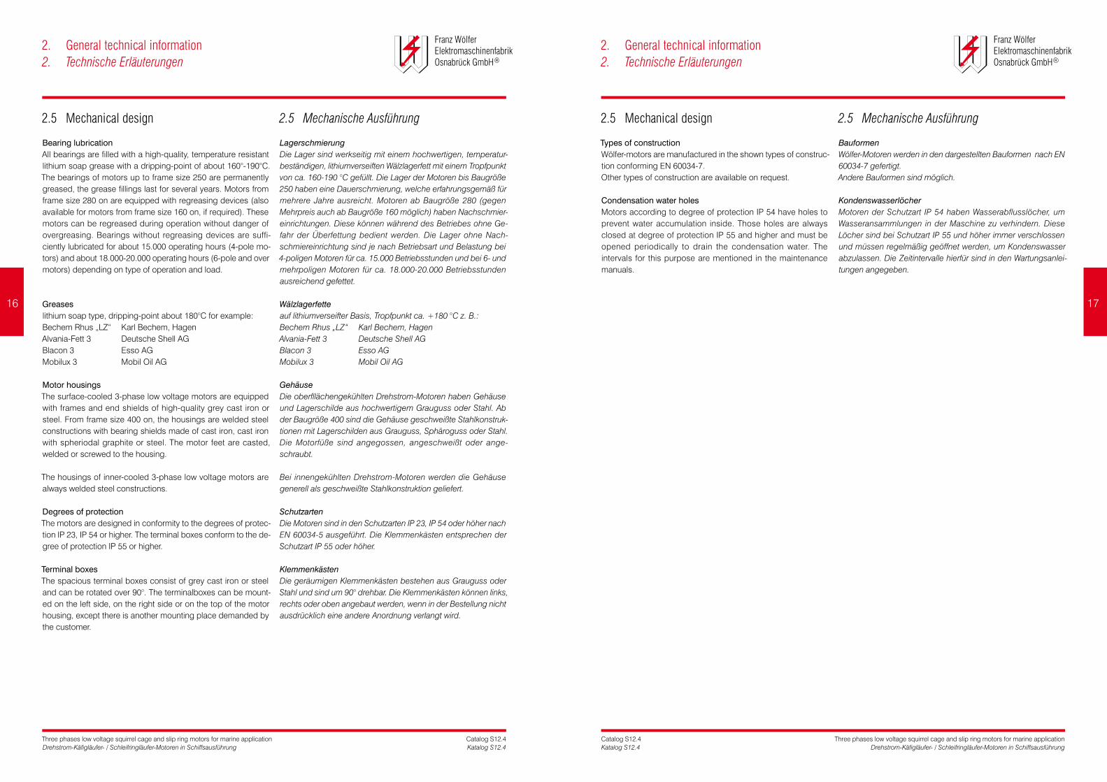
BearinglubricationAll bearings are filled with a high-quality, temperature resistant lithium soap grease with a dripping-point of about 160°-190°C. The bearings of motors up to frame size 250 are permanently greased, the grease fillings last for several years. Motors from frame size 280 on are equipped with regreasing devices (also available for motors from frame size 160 on, if required). These motors can be regreased during operation without danger of overgreasing. Bearings without regreasing devices are suffi-ciently lubricated for about 15.000 operating hours (4-pole mo-tors) and about 18.000-20.000 operating hours (6-pole and over motors) depending on type of operation and load.
Greaseslithium soap type, dripping-point about 180°C for example:Bechem Rhus „LZ“ Karl Bechem, HagenAlvania-Fett 3 Deutsche Shell AGBlacon 3 Esso AGMobilux 3 Mobil Oil AG
MotorhousingsThe surface-cooled 3-phase low voltage motors are equipped with frames and end shields of high-quality grey cast iron or steel. From frame size 400 on, the housings are welded steel constructions with bearing shields made of cast iron, cast iron with spheriodal graphite or steel. The motor feet are casted, welded or screwed to the housing.
The housings of inner-cooled 3-phase low voltage motors are always welded steel constructions.
DegreesofprotectionThe motors are designed in conformity to the degrees of protec-tion IP 23, IP 54 or higher. The terminal boxes conform to the de-gree of protection IP 55 or higher.
TerminalboxesThe spacious terminal boxes consist of grey cast iron or steel and can be rotated over 90°. The terminalboxes can be mount-ed on the left side, on the right side or on the top of the motor housing, except there is another mounting place demanded by the customer.
2.5 Mechanische Ausführung
LagerschmierungDie Lager sind werkseitig mit einem hochwertigen, temperatur-beständigen, lithiumverseiften Wälzlagerfett mit einem Tropfpunkt von ca. 160-190 °C gefüllt. Die Lager der Motoren bis Baugröße 250 haben eine Dauerschmierung, welche erfahrungsgemäß für mehrere Jahre ausreicht. Motoren ab Baugröße 280 (gegen Mehrpreis auch ab Baugröße 160 möglich) haben Nachschmier-einrichtungen. Diese können während des Betriebes ohne Ge-fahr der Überfettung bedient werden. Die Lager ohne Nach-schmiereinrichtung sind je nach Betriebsart und Belastung bei 4-poligen Motoren für ca. 15.000 Betriebsstunden und bei 6- und mehrpoligen Motoren für ca. 18.000-20.000 Betriebsstunden ausreichend gefettet.
Wälzlagerfetteauf lithiumverseifter Basis, Tropfpunkt ca. +180 °C z. B.:Bechem Rhus „LZ“ Karl Bechem, HagenAlvania-Fett 3 Deutsche Shell AGBlacon 3 Esso AGMobilux 3 Mobil Oil AG
GehäuseDie oberfllächengekühlten Drehstrom-Motoren haben Gehäuse und Lagerschilde aus hochwertigem Grauguss oder Stahl. Ab der Baugröße 400 sind die Gehäuse geschweißte Stahlkonstruk-tionen mit Lagerschilden aus Grauguss, Sphäroguss oder Stahl. Die Motorfüße sind angegossen, angeschweißt oder ange-schraubt.
Bei innengekühlten Drehstrom-Motoren werden die Gehäuse generell als geschweißte Stahlkonstruktion geliefert.
SchutzartenDie Motoren sind in den Schutzarten IP 23, IP 54 oder höher nach EN 60034-5 ausgeführt. Die Klemmenkästen entsprechen der Schutzart IP 55 oder höher.
KlemmenkästenDie geräumigen Klemmenkästen bestehen aus Grauguss oder Stahl und sind um 90° drehbar. Die Klemmenkästen können links, rechts oder oben angebaut werden, wenn in der Bestellung nicht ausdrücklich eine andere Anordnung verlangt wird.
2.5 Mechanical design
TypesofconstructionWölfer-motors are manufactured in the shown types of construc-tion conforming EN 60034-7. Other types of construction are available on request.
CondensationwaterholesMotors according to degree of protection IP 54 have holes to prevent water accumulation inside. Those holes are always closed at degree of protection IP 55 and higher and must be opened periodically to drain the condensation water. The intervals for this purpose are mentioned in the maintenance manuals.
2.5 Mechanische Ausführung
BauformenWölfer-Motoren werden in den dargestellten Bauformen nach EN 60034-7 gefertigt.Andere Bauformen sind möglich.
KondenswasserlöcherMotoren der Schutzart IP 54 haben Wasserabflusslöcher, um Wasseransammlungen in der Maschine zu verhindern. Diese Löcher sind bei Schutzart IP 55 und höher immer verschlossen und müssen regelmäßig geöffnet werden, um Kondenswasser abzulassen. Die Zeitintervalle hierfür sind in den Wartungsanlei-tungen angegeben.
2. General technical information2. Technische Erläuterungen
2. General technical information2. Technische Erläuterungen
16 17

Three phases low voltage squirrel cage and slip ring motors for marine applicationDrehstrom-Käfigläufer- / Schleifringläufer-Motoren in Schiffsausführung
Catalog S12.4Katalog S12.4
Three phases low voltage squirrel cage and slip ring motors for marine applicationDrehstrom-Käfigläufer- / Schleifringläufer-Motoren in Schiffsausführung
Catalog S12.4Katalog S12.4
2.6 More components
2.6.1 Methods of cooling acc. EN 60034-6
As a principle, motors can be sectioned into three categories:• motors with surface cooling• motors with inner cooling• motors with heat exchangers
Motorswithsurfacecoolingaccording to class of protection IP 54, IP 55 and IP 56 are offered as three different variations:1. without ventilation → type of cooling IC 4102. self-ventilated → type of cooling IC 4113. forced ventilated → type of cooling IC 416
Motorswithinnercoolingaccording to class of protection IP 23 are offered as three variations:1. self ventilated → type of cooling IC 012. forced ventilated → type of cooling IC 063. air-water-cooler → type of cooling IC 86 W
MotorswithheatexchangersIn most cases, water is used as cooling medium. Heat exchang-ers can also be manufactured for air as cooling medium, if de-sired.
Therefore a heat exchanger is mounted on top or aside a motor designed for inner ventilation.
Two independent working cooling circles are active. Within the primary motor cooling circle, hot exhaust air of the motor is pressed through the radiator coils of the heat exchanger by a separately driven fan, cools down and is blown into the motor again. Within the second cooling circle, water respectively air is used to cool the radiator coils.
Motors equipped with heat exchangers comply to the degree of protection IP 54R (R=tube connected).
2.6 Weitere Komponenten
2.6.1 KühlverfahrennachEN60034-6
Grundsätzlich werden die Motoren in drei Kategorien unterteilt:• Motoren mit Oberflächenkühlung• Motoren mit Durchzugsbelüftung• Motoren mit angebautem Wärmetauscher
OberflächengekühlteMotorender Schutzarten IP 54, IP 55 und IP 56 werden in drei verschie-denen Varianten angeboten:1. ohne Lüfter → Kühlart IC 4102. mit Eigenlüfter → Kühlart IC 4113. mit Fremdlüfter → Kühlart IC 416
MotorenmitDurchzugsbelüftungin der Schutzart IP 23 werden in drei Varianten angeboten:
1. mit Eigenlüfter → Kühlart IC 012. mit Fremdlüfter → Kühlart IC 063. mit Wärmetauscher → Kühlart IC 86 W
MotorenmitangebautemWärmetauscherHier wird als Kühlmittel vorzugsweise Wasser verwendet. Wärme-tauscher können auf Wunsch auch mit Luft als sekundärem Kühl-medium gefertigt werden.
Hierbei wird ein Wärmetauscher (oben oder seitlich) an einem für Durchzugsbelüftung konstruierten Motor montiert.
Es sind zwei unabhängig voneinander wirkende Kühlkreise aktiv. Im primären Motorkühlkreis wird erwärmte Luft mittels eines se-parat angetriebenen Lüfters durch die Kühlelemente des Wärme-tauschers gedrückt und als erkaltete Luft dem Motor wieder zu-geführt. Im sekundären Kühlkreis dient Wasser bzw. Luft als Kühl-medium für den primären Kühlkreis.
Motoren mit angebautem Wärmetauscher haben die Schutzart IP 54R (R=Rohranschluss).
2.6.2 Forced cooling fans
Preferably, the motors designed for the class of protection IP 54 are equipped with axial working forced cooling fans mounted in a lengthened fan cover and provided with an own terminal box. In the standard version its position corresponds to that of the main motor. The main circuit connection is 400 Volts-50 Hz respectively 440 Volts-60 Hz. Optionally, the seperately driven fans can be also delivered for other voltages or frequences. Also the mounting position of the forced cooling fan can be changed.
A selection of forced cooling fans is shown in the table below:
2.6.2 Fremdlüfter
Vorzugsweise werden bei den Motoren der Schutzart IP 54 Axial-ventilatoren eingesetzt, die in eine verlängerte Motorhaube ein-gebaut sind und einen separaten Klemmenkasten haben. Die Lage des Klemmenkastens entspricht in der Standardausführung der des Hauptantriebes. Die Anschlussspannung beträgt 400 Volt-50 Hz bzw. 440 Volt-60 Hz. Auf Wunsch können die Fremdlüfter auch für andere Spannungen und Frequenzen gelie-fert werden. Ebenso kann eine andere Anbauposition des Geblä-ses gewählt werden.
In der Tabelle ist eine Auswahl der Fremdlüftertypen dargestellt:
2. General technical information2. Technische Erläuterungen
2. General technical information 2. Technische Erläuterungen
motor type fan type Current (at 400 Volts)
Speed (min-¹) noise level (dB(A))
Motortype Lüftertype Nennstrom(A)(bei400Volt)
Drehzahl(min-¹) Geräuschpegel(dB(A))
MDRKF 160 FBI 160-4 0,63 1410 69
MDRKF 180 FBI 180-4 0,66 1340 72
MDRKF 200 FBI 200-4 0,72 1340 78
MDRKF 225 FBI 225-4 1,20 1370 78
MDRKF 250 FBI 250-4 1,79 1400 80
MDRKF 280 FBI 280-4 1,82 1370 83
MDRKF 315 FBI 315-4 1,84 1400 85
MDRKF 355 FBI 355-4 3,80 1400 85
MDRKF 400 FBI 400-4 3,80 1400 85
18 19

Three phases low voltage squirrel cage and slip ring motors for marine applicationDrehstrom-Käfigläufer- / Schleifringläufer-Motoren in Schiffsausführung
Catalog S12.4Katalog S12.4
Three phases low voltage squirrel cage and slip ring motors for marine applicationDrehstrom-Käfigläufer- / Schleifringläufer-Motoren in Schiffsausführung
Catalog S12.4Katalog S12.4
2.6.2 Forced cooling fans
The motors designed for the class of protection IP 23 are equipped with radial working forced cooling fans. Usually they are mounted on top of the motor at the non-drive-end. The forced cooling fans have a main circuit connection of 400 Volts-50 Hz and are equipped with an own terminal box. Option-ally, the seperately driven fans can be also delivered for other voltages or frequences. Also the mounting position of the forced cooling fan can be changed.
A selection of forced cooling fans is shown in the table:
2.6.2 Fremdlüfter
Bei den Motoren der Schutzart IP 23 werden Radialventilatoren eingesetzt. Der Anbau wird normalerweise auf der Nichtantriebs-seite oben vorgenommen. Die Gebläse sind für eine Anschluss-spannung von 400 Volt-50 Hz ausgelegt und haben einen eigenen Klemmenkasten. Auf Wunsch können die Fremdlüfter auch für andere Spannungen und Frequenzen geliefert werden. Ebenso kann eine andere Anbauposition des Gebläses gewählt werden.
In der Tabelle ist eine Auswahl der Fremdlüftertypen dargestellt:
2. General technical information2. Technische Erläuterungen
2. General technical information2. Technische Erläuterungen
2.6.3 Brakes
Our motors can be equipped with brakes of all well-known brake manufacturers (Pintsch Bubenzer), with different static and/or dynamic brake torque. The brakes can be carried out either as stop-brakes with emergency-stop function or as working brakes. All brakes are spring-loaded, electrically released brakes, which stop without supply and which are released electromechanical-ly when fed by DC voltage. The preferred rated voltages are 110 V DC and 207 V DC.
Concerning the connections of the brakes, please contact us.
2.6.4 Encoders
As a principle, all available encoders can be mounted on our motors. The couplings are insulated, so that no shaft-current can be transferred to the encoder from the motor. Types of construc-tion B 10 (POG Hübner, RCI-REO, etc.) are preferred for encod-ers, mounted directly to the brakes of motors without ventilator (type of cooling IC 410)
For Encoders mounted to the fan cover of the motor (IC 411) we recommend hollow shaft encoders (HOG Hübner, ITD-Thalheim etc.).
2.6.3 Bremsen
Es können Bremsen aller namhaften Hersteller (Pintsch Buben-zer) mit unterschiedlichen statischen und/oder dynamischen Bremsmomenten eingesetzt werden. Die Bremsen können als reine Haltebremsen mit Notstopfunktion oder als Betriebsbrem-sen ausgeführt werden. Es handelt sich um federbelastete, elek-trisch gelüftete Bremsen, die in spannungslosem Zustand ge-bremst sind und bei Anlegen einer Gleichspannung elektromag-netisch lüften. Die Vorzugsspannungen der Bremsen betragen 110 V DC und 207 V DC.
Bezüglich der Beschaltung bitten wir um Rücksprache.
2.6.4 Encoder
Grundsätzlich sind alle auf dem Markt erhältlichen Encoder an-zubauen. Die Kupplungen sind isoliert, so dass keine Wellenströ-me von der Antriebsmaschine übertragen werden können. Für Motoren ohne Eigenlüfter, bei denen die Encoder direkt an die Haltebremse gebaut werden (Kühlart IC 410), werden B 10 Bau-formen bevorzugt (POG-Hübner, RCI-REO etc.).
Bei Motoren, deren Encoder an der Motorhaube angebracht wer-den muss (IC 411), empfehlen wir Hohlwellengeber (HOG Hüb-ner, ITD-Thalheim etc.).
motor type fan type Current (at 400 Volts)
Speed (min-¹) noise level (dB(A))
-2dB(A)with Filter
Motortype Lüftertype Nennstrom(A)(bei400Volt)
Drehzahl(min-¹)
Geräuschpegel(dB(A))
-2dB(A)mitFilter
MODRKF 225 DNG 6-25 2,1 2880 79 77
MODRKF 250 DNG 7-60 4,2 2840 82 80
MODRKF 280 DNG 8-80 4,9 2870 84 82
MODRKF 315 DNG 9-90 8,5 2880 85 83
MODRKF 355 DNG 9-90 11,2 2900 87 85
MODRKF 400 DNG 9-90 11,2 2900 87 85
20 21

MOTORDATALEISTUNGSTABELLEN

Three phases low voltage squirrel cage and slip ring motors for marine applicationDrehstrom-Käfigläufer- / Schleifringläufer-Motoren in Schiffsausführung
Catalog S12.4Katalog S12.4
Three phases low voltage squirrel cage and slip ring motors for marine applicationDrehstrom-Käfigläufer- / Schleifringläufer-Motoren in Schiffsausführung
Catalog S12.4Katalog S12.4
Type of operation S2-30‘ Type of operation S2-60‘ Type of operation S1
Type P (kW) IN (A) TS/TN IA/IN P (kW) IN (A) TS/TN IA/IN P (kW) IN (A) TS/TN IA/IN n(rpm) m (kg) J (kgm²)
225S-4 55 100 1,7 4,6 45 82 2,1 5,7 37 67 2,6 6,9 1470 320 0,36
225M-4 65 118 1,8 4,8 55 100 2,1 5,6 45 82 2,6 6,9 1470 365 0,43
225M-4bb 70 128 1,9 4,9 60 109 2,2 5,8 50 91 2,6 6,9 1470 435 0,52
250M-4 75 134 1,8 5,0 65 116 2,1 5,8 55 99 2,5 6,8 1475 435 0,62
250M-4b 85 152 1,8 5,0 75 134 2,1 5,6 62 111 2,5 6,8 1475 485 0,73
250M-4bb 95 170 1,8 5,0 85 152 2,1 5,6 70 125 2,5 6,8 1475 525 0,84
280S-4 105 184 1,9 4,9 90 158 2,2 5,8 75 131 2,6 6,9 1480 595 1,01
280M-4 125 219 1,9 5,0 105 184 2,2 5,9 90 158 2,6 6,9 1480 640 1,21
280M-4b 145 254 1,9 5,0 125 219 2,2 5,8 105 184 2,6 6,9 1480 690 1,46
315S-4 160 274 1,9 4,9 132 226 2,3 5,9 110 189 2,7 7,1 1485 920 2,87
315M-4 190 326 1,9 4,9 160 274 2,2 5,9 132 226 2,7 7,1 1485 980 3,11
315M-4b 220 377 2,0 5,2 190 326 2,3 6,0 160 274 2,7 7,1 1485 1015 3,77
315L-4 270 463 2,0 5,1 230 394 2,3 6,0 195 334 2,7 7,1 1485 1165 4,15
315L-4b 300 514 1,9 5,0 250 429 2,3 6,0 210 360 2,7 7,1 1485 1200 4,35
315L-4bb 330 566 2,0 5,2 285 489 2,3 6,0 240 411 2,7 7,1 1485 1250 4,64
315L-4bbb 360 617 2,0 5,1 300 514 2,3 6,2 260 446 2,7 7,1 1485 1300 4,71
315X-4 400 686 1,9 5,0 330 566 2,3 6,0 280 480 2,7 7,1 1485 1340 4,81
355L-4 425 713 1,0 4,9 350 587 1,2 5,9 300 503 1,4 6,9 1490 1400 6,44
355L-4b 470 788 1,0 5,0 400 671 1,2 5,9 340 570 1,4 6,9 1490 1550 7,29
355L-4bb 520 872 1,0 5,0 450 755 1,2 5,8 375 629 1,4 6,9 1490 1685 8,22
355L-4bbb 600 1006 1,0 4,9 500 839 1,2 5,9 425 713 1,4 6,9 1490 1860 9,62
355X-4 660 1107 1,0 5,0 550 923 1,2 6,0 475 797 1,4 6,9 1490 1920 10,09
400L-4b 730 1205 0,9 4,8 600 990 1,1 5,9 520 858 1,3 6,8 1495 2780 12,61
400L-4bb 840 1386 0,9 4,9 700 1155 1,1 5,8 600 990 1,3 6,8 1495 2985 14,32
400L-4bbb 900 1485 0,9 4,9 760 1254 1,1 5,8 650 1073 1,3 6,8 1495 3220 15,51
400X-4 1000 1650 0,9 4,9 850 1403 1,1 5,8 725 1197 1,3 6,8 1495 3450 17,32
450L-4b 1050 1705 0,9 4,8 880 1429 1,0 5,7 750 1218 1,2 6,7 1495 4120 20,66
450L-4bb 1200 1949 0,9 4,7 1000 1624 1,0 5,7 850 1380 1,2 6,7 1495 4460 23,24
450L-4bbb 1300 2111 0,9 4,9 1100 1786 1,0 5,8 950 1543 1,2 6,7 1495 4870 25,83
450X-4 1400 2274 0,9 4,8 1180 1916 1,0 5,7 1000 1624 1,2 6,7 1495 5110 27,93
Type of operation S2-30‘ Type of operation S2-60‘ Type of operation S1
Type P (kW) IN (A) TS/TN IA/IN P (kW) IN (A) TS/TN IA/IN P (kW) IN (A) TS/TN IA/IN n(rpm) m (kg) J (kgm²)
225S-4 65 107 1,8 4,8 55 91 2,6 6,9 45 74 2,6 6,9 1770 320 0,36
225M-4 75 124 1,9 5,1 65 107 2,6 6,9 55 91 2,6 6,9 1770 365 0,43
225M-4bb 85 140 1,8 4,9 70 115 2,6 6,9 60 99 2,6 6,9 1770 435 0,52
250M-4 90 146 1,8 4,9 75 122 2,5 6,8 65 105 2,5 6,8 1775 435 0,62
250M-4b 105 170 1,8 4,9 90 146 2,5 6,8 75 122 2,5 6,8 1775 485 0,73
250M-4bb 120 195 1,8 4,8 100 162 2,5 6,8 85 138 2,5 6,8 1775 525 0,84
280S-4 125 198 1,9 5,0 110 175 2,6 6,9 90 143 2,6 6,9 1780 595 1,01
280M-4 155 246 1,8 4,9 132 209 2,6 6,9 110 175 2,6 6,9 1780 640 1,21
280M-4b 175 278 1,9 4,9 150 238 2,6 6,9 125 198 2,6 6,9 1780 690 1,46
315S-4 185 287 1,9 5,1 160 248 2,7 7,1 132 205 2,7 7,1 1785 920 2,87
315M-4 225 349 1,9 5,0 190 295 2,7 7,1 160 248 2,7 7,1 1785 980 3,11
315M-4b 265 411 1,9 5,1 220 341 2,7 7,1 190 295 2,7 7,1 1785 1015 3,77
315L-4 320 497 1,9 5,1 270 419 2,7 7,1 230 357 2,7 7,1 1785 1165 4,15
315L-4b 350 543 1,9 5,1 290 450 2,7 7,1 250 388 2,7 7,1 1785 1200 4,35
315L-4bb 400 621 2,0 5,1 340 528 2,7 7,1 290 450 2,7 7,1 1785 1250 4,64
315L-4bbb 430 667 1,9 5,1 360 559 2,7 7,1 310 481 2,7 7,1 1785 1300 4,71
315X-4 460 714 1,9 5,1 390 605 2,7 7,1 330 512 2,7 7,1 1785 1340 4,81
355L-4 500 759 1,0 5,0 425 646 1,4 6,9 360 547 1,4 6,9 1790 1400 6,44
355L-4b 560 851 1,0 4,9 470 714 1,4 6,9 400 608 1,4 6,9 1790 1550 7,29
355L-4bb 630 957 1,0 4,9 530 805 1,4 6,9 450 684 1,4 6,9 1790 1685 8,22
355L-4bbb 700 1063 1,0 5,0 600 911 1,4 6,9 510 775 1,4 6,9 1790 1860 9,62
355X-4 800 1215 1,0 4,9 670 1018 1,4 6,9 570 866 1,4 6,9 1790 1920 10,09
400L-4b 880 1315 0,9 4,9 750 1121 1,3 6,8 630 941 1,3 6,8 1795 2780 12,61
400L-4bb 1000 1494 0,9 5,0 860 1285 1,3 6,8 730 1091 1,3 6,8 1795 2985 14,32
400L-4bbb 1100 1644 0,9 4,8 920 1375 1,3 6,8 780 1166 1,3 6,8 1795 3220 15,51
400X-4 1200 1793 0,9 4,9 1000 1494 1,3 6,8 870 1300 1,3 6,8 1795 3450 17,32
450L-4b 1250 1838 0,9 4,8 1050 1544 1,2 6,7 900 1324 1,2 6,7 1795 4120 20,66
450L-4bb 1400 2059 0,9 4,8 1150 1691 1,2 6,7 1000 1471 1,2 6,7 1795 4460 23,24
450L-4bbb 1600 2353 0,9 4,8 1350 1985 1,2 6,7 1150 1691 1,2 6,7 1795 4870 25,83
450X-4 1700 2500 0,8 4,7 1400 2059 1,2 6,7 1200 1765 1,2 6,7 1795 5110 27,93
3. Motordata3. Leistungstabellen
3. Motordata3. Leistungstabellen
Power at 400 Volt-50 Hz-1500 rpm Enclosure IP 54Mounting of position IMV1Insulations class F
6 x PTCanticondensation heaterAmbient temperature 45 °CIC 411
Leistungbei400Volt-50Hz-1500rpmSchutzart IP 54Bauform IMV1Isolationsklasse F
6 x PTCStillstandsheizungUmgebungstemperatur 45 °CIC 411
Power at 440 Volt-60 Hz-1800 rpm Enclosure IP 54Mounting of position IMV1Insulations class F
6 x PTCanticondensation heaterAmbient temperature 45 °CIC 411
Leistungbei440Volt-60Hz-1800rpm Schutzart IP 54Bauform IMV1Isolationsklasse F
6 x PTCStilstandsheizungUmgebungstemperatur 45 °CIC 411
3.1 Squirrel cage motors 3.1 Käfigläufer-Motoren 3.1 Squirrel cage motors 3.1 Käfigläufer-Motoren
Type: MDK Type: MDK
24 25

Three phases low voltage squirrel cage and slip ring motors for marine applicationDrehstrom-Käfigläufer- / Schleifringläufer-Motoren in Schiffsausführung
Catalog S12.4Katalog S12.4
Three phases low voltage squirrel cage and slip ring motors for marine applicationDrehstrom-Käfigläufer- / Schleifringläufer-Motoren in Schiffsausführung
Catalog S12.4Katalog S12.4
Type of operation S2-30‘ Type of operation S2-60‘ Type of operation S1
Type P (kW) IN (A) TS/TN IA/IN P (kW) IN (A) TS/TN IA/IN P (kW) IN (A) TS/TN IA/IN n(rpm) m (kg) J (kgm²)
225M-6 40 77 1,4 4,8 33 63 1,7 5,8 28 54 2,0 6,8 970 360 0,62
225M-6b 45 86 1,4 4,9 38 73 1,7 5,7 32 61 2,0 6,8 970 395 0,71
225M-6bb 50 96 1,4 4,8 41 79 1,7 5,8 35 67 2,0 6,8 970 435 0,77
250M-6 55 103 1,3 4,5 45 84 1,6 5,5 37 69 1,9 6,7 975 495 0,86
250M-6b 65 122 1,3 4,6 55 103 1,6 5,5 45 84 1,9 6,7 975 545 1,05
250M-6bb 70 131 1,4 4,8 60 113 1,6 5,6 50 94 1,9 6,7 975 595 1,16
280M-6 80 147 1,4 4,5 65 119 1,7 5,6 55 101 2,0 6,6 980 720 1,41
280M-6b 105 193 1,4 4,7 90 165 1,7 5,5 75 138 2,0 6,6 980 790 1,91
280M-6bb 120 220 1,4 4,7 100 184 1,7 5,6 85 156 2,0 6,6 980 820 2,29
315S-6 125 224 1,2 4,7 105 188 1,4 5,6 90 162 1,6 6,5 985 925 2,56
315M-6 135 242 1,1 4,6 110 197 1,4 5,6 95 171 1,6 6,5 985 980 2,86
315M-6b 150 269 1,1 4,6 125 224 1,3 5,5 105 188 1,6 6,5 985 1040 3,11
315L-6 175 314 1,1 4,6 150 269 1,3 5,4 125 224 1,6 6,5 985 1150 3,66
315L-6b 200 359 1,2 4,7 170 305 1,4 5,5 145 260 1,6 6,5 985 1250 4,35
315L-6bb 225 404 1,1 4,6 190 341 1,3 5,5 160 287 1,6 6,5 985 1300 4,61
315L-6bbb 250 449 1,2 4,7 210 377 1,4 5,6 180 323 1,6 6,5 985 1380 4,71
315X-6 280 503 1,1 4,6 235 422 1,4 5,5 200 359 1,6 6,5 985 1420 5,76
355L-6 315 556 1,0 4,6 260 459 1,3 5,6 220 388 1,5 6,6 990 1690 6,77
355L-6b 375 662 1,1 4,7 315 556 1,3 5,6 265 468 1,5 6,6 990 1760 8,41
355L-6bb 440 776 1,1 4,7 375 662 1,3 5,5 315 556 1,5 6,6 990 1850 8,35
355L-6bbb 470 829 1,1 4,7 395 697 1,3 5,6 335 591 1,5 6,6 990 1950 8,72
355X-6 500 882 1,1 4,8 425 750 1,3 5,6 360 635 1,5 6,6 990 2000 10,8
400L-6b 560 972 1,0 4,8 470 816 1,2 5,7 400 694 1,4 6,7 990 2820 17,7
400L-6bb 630 1093 1,0 4,8 530 920 1,2 5,7 450 781 1,4 6,7 990 3010 19,2
400L-6bbb 700 1215 1,0 4,8 590 1024 1,2 5,7 500 868 1,4 6,7 990 3220 21,2
400X-6 770 1336 1,0 4,8 650 1128 1,2 5,7 550 954 1,4 6,7 990 3860 24,1
450L-6b 840 1434 0,9 4,8 700 1195 1,1 5,7 600 1024 1,3 6,7 995 4040 29,2
450L-6bb 910 1553 0,9 4,8 750 1280 1,1 5,8 650 1109 1,3 6,7 995 4380 32,1
450L-6bbb 1000 1707 0,9 4,9 850 1451 1,1 5,8 730 1246 1,3 6,7 995 4620 35,7
450X-6 1100 1877 0,9 4,9 950 1621 1,1 5,6 800 1365 1,3 6,7 995 4870 38,3
500L-6b 1150 1931 0,9 4,8 980 1645 1,1 5,6 830 1393 1,3 6,6 995 5290 56,2
500L-6bb 1250 2098 0,9 4,8 1050 1763 1,1 5,7 900 1511 1,3 6,6 995 5680 63,4
500L-6bbb 1350 2266 0,9 4,8 1150 1931 1,1 5,6 980 1645 1,3 6,6 995 5850 73,6
Type of operation S2-30‘ Type of operation S2-60‘ Type of operation S1
Type P (kW) IN (A) TS/TN IA/IN P (kW) IN (A) TS/TN IA/IN P (kW) TS/TN IA/IN n(rpm) m (kg) J (kgm²)
225M-6 45 86 1,5 5,0 37 71 1,8 6,1 33 2,0 6,8 970 360 0,62
225M-6b 50 96 1,5 5,0 41 79 1,8 6,1 37 2,0 6,8 970 395 0,71
225M-6bb 55 106 1,5 4,9 45 86 1,8 6,0 40 2,0 6,8 970 435 0,77
250M-6 60 113 1,4 5,0 50 94 1,7 6,0 45 1,9 6,7 975 495 0,86
250M-6b 75 141 1,4 4,9 65 122 1,6 5,7 55 1,9 6,7 975 545 1,05
250M-6bb 80 150 1,4 5,0 70 131 1,6 5,7 60 1,9 6,7 975 595 1,16
280M-6 90 165 1,4 4,8 75 138 1,7 5,7 65 2,0 6,6 980 720 1,41
280M-6b 110 202 1,5 5,1 95 174 1,8 5,9 85 2,0 6,6 980 790 1,91
280M-6bb 132 242 1,5 5,0 110 202 1,8 6,0 100 2,0 6,6 980 820 2,29
315S-6 140 251 1,2 4,9 115 206 1,5 5,9 105 1,6 6,5 985 925 2,56
315M-6 150 269 1,2 4,8 125 224 1,4 5,7 110 1,6 6,5 985 980 2,56
315M-6b 170 305 1,2 4,8 145 260 1,4 5,6 125 1,6 6,5 985 1040 2,88
315L-6 200 359 1,2 4,9 175 314 1,4 5,6 150 1,6 6,5 985 1150 3,66
315L-6b 230 413 1,2 4,8 195 350 1,4 5,7 170 1,6 6,5 985 1250 4,35
315L-6bb 250 449 1,2 4,9 220 395 1,4 5,6 190 1,6 6,5 985 1300 4,61
315L-6bbb 280 503 1,2 4,9 240 431 1,4 5,7 210 1,6 6,5 985 1380 4,71
315X-6 315 565 1,2 4,8 270 485 1,4 5,7 235 1,6 6,5 985 1420 5,76
355L-6 350 618 1,1 4,9 300 529 1,3 5,7 260 1,5 6,6 990 1690 6,77
355L-6b 420 741 1,1 5,0 360 635 1,3 5,8 315 1,5 6,6 990 1760 8,41
355L-6bb 500 882 1,1 5,0 430 759 1,3 5,8 375 1,5 6,6 990 1850 8,35
355L-6bbb 530 935 1,1 4,9 460 812 1,3 5,7 395 1,5 6,6 990 1950 8,72
355X-6 570 1006 1,1 4,9 490 865 1,3 5,7 425 1,5 6,6 990 2000 10,8
400L-6b 630 1093 1,0 5,0 540 937 1,2 5,8 470 1,4 6,7 990 2820 17,7
400L-6bb 710 1232 1,0 5,0 610 1058 1,2 5,8 530 1,4 6,7 990 3010 19,2
400L-6bbb 800 1388 1,0 4,9 680 1180 1,2 5,8 590 1,4 6,7 990 3220 21,2
400X-6 880 1527 1,0 4,9 750 1301 1,2 5,8 650 1,4 6,7 990 3860 24,1
450L-6b 950 1621 1,0 5,0 810 1382 1,1 5,9 710 1,3 6,7 995 4040 29,2
450L-6bb 1020 1741 1,0 5,0 870 1485 1,1 5,9 760 1,3 6,7 995 4380 32,1
450L-6bbb 1150 1963 1,0 5,0 980 1673 1,1 5,9 860 1,3 6,7 995 4620 35,7
450X-6 1280 2184 1,0 5,0 1090 1860 1,1 5,8 950 1,3 6,7 995 4870 38,3
500L-6b 1320 2216 1,0 4,9 1130 1897 1,1 5,7 980 1,3 6,6 995 5290 56,2
500L-6bb 1400 2350 1,0 5,0 1200 2015 1,1 5,8 1050 1,3 6,6 995 5680 63,4
500L-6bbb 1550 2602 1,0 4,9 1320 2216 1,1 5,8 1150 1,3 6,6 995 5850 73,6
3. Motordata3. Leistungstabellen
3. Motordata3. Leistungstabellen
Power at 400 Volt-50 Hz-1000 rpm Enclosure IP 54Mounting of position IMV1Insulations class F
6 x PTCanticondensation heaterAmbient temperature 45 °CIC 411
Leistungbei400Volt-50Hz-1000rpm Schutzart IP 54Bauform IMV1Isolationsklasse F
6 x PTCStillstandsheizungUmgebungstemperatur 45 °CIC 411
Power at 440 Volt-60 Hz-1200 rpm Enclosure IP 54Mounting of position IMV1Insulations class F
6 x PTCanticondensation heaterAmbient temperature 45 °CIC 411
Leistungbei440Volt-60Hz-1200rpmSchutzart IP 54Bauform IMV1Isolationsklasse F
6 x PTCStillstandsheizungUmgebungstemperatur 45 °CIC 411
3.1 Squirrel cage motors 3.1 Käfigläufer-Motoren 3.1 Squirrel cage motors 3.1 Käfigläufer-Motoren
Type: MDK Type: MDK
26 27

Three phases low voltage squirrel cage and slip ring motors for marine applicationDrehstrom-Käfigläufer- / Schleifringläufer-Motoren in Schiffsausführung
Catalog S12.4Katalog S12.4
Three phases low voltage squirrel cage and slip ring motors for marine applicationDrehstrom-Käfigläufer- / Schleifringläufer-Motoren in Schiffsausführung
Catalog S12.4Katalog S12.4
Type of operation S2-30‘ Type of operation S2-60‘ Type of operation S1
Type P (kW) IN (A) TS/TN IA/IN P (kW) IN (A) TS/TN IA/IN P (kW) IN (A) TS/TN IA/IN n(rpm) m (kg) J (kgm²)
160M-4 11 22 2,0 6,0 7,5 15 2,2 6,5 5,5 11 2,6 7,8 1460 100 0,06
160L-4 15 29 2,0 6,0 10 20 2,2 6,5 7,5 15 2,6 7,8 1460 125 0,09
180M-4 18 35 1,9 6,0 12 24 2,1 6,5 9,2 18 2,5 7,8 1465 160 0,13
180L-4 22 42 1,9 6,0 15 29 2,1 6,5 11,0 21 2,5 7,8 1465 180 0,16
180L-4b 25 48 1,9 6,0 17 33 2,1 6,5 12,5 24 2,5 7,8 1465 200 0,18
200L-4 30 56 1,8 5,8 21 38 2,0 6,3 15,0 28 2,4 7,6 1470 240 0,26
200L-4b 35 66 1,8 5,8 24 45 2,0 6,3 18,0 33 2,4 7,6 1470 265 0,3
225S-4 37 68 1,8 5,8 26 46 1,9 6,3 19 34 2,3 7,6 1475 320 0,36
225M-4 45 83 1,8 5,8 30 57 1,9 6,3 22 42 2,3 7,6 1475 365 0,43
225M-4b 50 92 1,8 5,8 34 63 1,9 6,3 25 46 2,3 7,6 1475 435 0,52
250M-4 55 99 1,8 5,8 37 68 1,9 6,3 27 50 2,3 7,5 1480 435 0,62
250M-4b 60 108 1,8 5,8 40 74 1,9 6,3 30 54 2,3 7,5 1480 485 0,73
250M-4bb 70 125 1,8 5,8 47 85 1,9 6,3 35 63 2,3 7,5 1480 525 0,84
280S-4 75 132 1,5 5,8 50 90 1,6 6,3 37 66 1,9 7,5 1485 595 1,01
280M-4 90 158 1,5 5,8 65 108 1,6 6,3 45 79 1,9 7,5 1485 640 1,21
280M-4b 100 175 1,5 5,8 70 119 1,6 6,3 50 88 1,9 7,5 1485 690 1,46
315S-4 110 189 1,4 5,7 75 129 1,5 6,2 55 95 1,8 7,4 1490 920 2,87
315M-4 120 206 1,4 5,7 85 140 1,5 6,2 60 103 1,8 7,4 1490 980 3,11
315M-4b 150 257 1,4 5,7 105 175 1,5 6,2 75 129 1,8 7,4 1490 1015 3,77
315L-4 160 274 1,4 5,7 110 187 1,5 6,2 80 137 1,8 7,4 1490 1165 4,15
315L-4b 180 309 1,4 5,7 125 211 1,5 6,2 90 155 1,8 7,4 1490 1200 4,35
315L-4bb 200 343 1,4 5,7 140 234 1,5 6,2 100 172 1,8 7,4 1490 1250 4,64
315L-4bbb 220 377 1,4 5,7 155 257 1,5 6,2 110 189 1,8 7,4 1490 1300 4,71
315X-4 260 446 1,4 5,7 180 304 1,5 6,2 132 223 1,8 7,4 1490 1340 4,81
355L-4 280 470 1,3 5,7 190 320 1,4 6,2 140 235 1,7 7,4 1495 1400 6,44
355L-4b 300 504 1,3 5,7 210 344 1,4 6,2 150 252 1,7 7,4 1495 1550 7,29
355L-4bb 320 537 1,3 5,7 220 366 1,4 6,2 160 269 1,7 7,4 1495 1685 8,22
355L-4bbb 350 588 1,3 5,7 240 401 1,4 6,2 175 294 1,7 7,4 1495 1860 9,68
355X-4 400 672 1,3 5,7 280 458 1,4 6,2 200 336 1,7 7,4 1495 1920 10,1
3. Motordata3. Leistungstabellen
3. Motordata3. Leistungstabellen
Type of operation S2-30‘ Type of operation S2-60‘ Type of operation S1
Type P (kW) IN (A) TS/TN IA/IN P (kW) IN (A) TS/TN IA/IN P (kW) IN (A) TS/TN IA/IN n(rpm) m (kg) J (kgm²)
160M-4 13 23 2,0 6,0 9 16 2,2 6,5 6,6 12 2,6 7,8 1760 100 0,06
160L-4 18 32 2,0 6,0 12 22 2,2 6,5 9 16 2,6 7,8 1760 125 0,09
180M-4 22 38 1,9 6,0 14 26 2,1 6,5 11 19 2,5 7,8 1765 160 0,13
180L-4 26 45 1,9 6,0 18 31 2,1 6,5 13 23 2,5 7,8 1765 180 0,16
180L-4b 30 52 1,9 6,0 20 35 2,1 6,5 15 26 2,5 7,8 1765 200 0,18
200L-4 36 63 1,8 5,8 25 43 2,0 6,3 18 32 2,4 7,6 1770 240 0,26
200L-4b 42 71 1,8 5,8 29 48 2,0 6,3 22 36 2,4 7,6 1770 265 0,3
225S-4 44 75 1,8 5,8 31 51 1,9 6,3 23 38 2,3 7,6 1775 320 0,36
225M-4 54 83 1,8 5,8 36 57 1,9 6,3 26 42 2,3 7,6 1775 365 0,43
225M-4b 60 100 1,8 5,8 41 68 1,9 6,3 30 50 2,3 7,6 1775 435 0,52
250M-4 66 106 1,8 5,8 44 72 1,9 6,3 32 53 2,3 7,5 1780 435 0,62
250M-4b 72 122 1,8 5,8 48 83 1,9 6,3 36 61 2,3 7,5 1780 485 0,73
250M-4bb 84 138 1,8 5,8 56 94 1,9 6,3 42 69 2,3 7,5 1780 525 0,84
280S-4 90 143 1,5 5,8 60 98 1,6 6,3 44 72 1,9 7,5 1785 595 1,01
280M-4 108 175 1,5 5,8 78 119 1,6 6,3 54 88 1,9 7,5 1785 640 1,21
280M-4b 120 191 1,5 5,8 84 130 1,6 6,3 60 96 1,9 7,5 1785 690 1,46
315S-4 132 205 1,4 5,7 90 140 1,5 6,2 66 103 1,8 7,4 1790 920 2,87
315M-4 144 233 1,4 5,7 102 159 1,5 6,2 72 117 1,8 7,4 1790 980 3,11
315M-4b 180 280 1,4 5,7 126 191 1,5 6,2 90 140 1,8 7,4 1790 1015 3,77
315L-4 192 295 1,4 5,7 132 201 1,5 6,2 96 148 1,8 7,4 1790 1165 4,15
315L-4b 216 326 1,4 5,7 150 222 1,5 6,2 108 163 1,8 7,4 1790 1200 4,35
315L-4bb 240 373 1,4 5,7 168 254 1,5 6,2 120 187 1,8 7,4 1790 1250 4,64
315L-4bbb 264 404 1,4 5,7 186 275 1,5 6,2 132 202 1,8 7,4 1790 1300 4,71
315X-4 312 497 1,4 5,7 216 339 1,5 6,2 158 249 1,8 7,4 1790 1340 4,81
355L-4 336 517 1,3 5,7 228 353 1,4 6,2 168 259 1,7 7,4 1795 1400 6,44
355L-4b 360 547 1,3 5,7 252 373 1,4 6,2 180 274 1,7 7,4 1795 1550 7,29
355L-4bb 384 578 1,3 5,7 264 394 1,4 6,2 192 289 1,7 7,4 1795 1685 8,22
355L-4bbb 420 638 1,3 5,7 288 435 1,4 6,2 210 319 1,7 7,4 1795 1860 9,68
355X-4 480 730 1,3 5,7 336 498 1,4 6,2 240 365 1,7 7,4 1795 1920 10,1
Power at 400 Volt-50 Hz-1500 rpm Enclosure IP 56Mounting of position IMV1Insulations class F
6 x PTCanticondensation heaterAmbient temperature 45 °CIC 410
Leistungbei400Volt-50Hz-1500rpm Schutzart IP 56Bauform IMV1Isolationsklasse F
6 x PTCStillstandsheizungUmgebungstemperatur 45 °CIC 410
Power at 440 Volt-60 Hz-1500 rpm Enclosure IP 56Mounting of position IMV1Insulations class F
6 x PTCanticondensation heaterAmbient temperature 45 °CIC 410
Leistungbei440Volt-60Hz-1500rpmSchutzart IP 56Bauform IMV1Isolationsklasse F
6 x PTCStillstandsheizungUmgebungstemperatur 45 °CIC 410
3.1 Squirrel cage motors 3.1 Käfigläufer-Motoren 3.1 Squirrel cage motors 3.1 Käfigläufer-Motoren
Type: MDKO Type: MDKO
28 29
Three phases low voltage squirrel cage and slip ring motors for marine applicationDrehstrom-Käfigläufer- / Schleifringläufer-Motoren in Schiffsausführung
Catalog S12.4Katalog S12.4
Three phases low voltage squirrel cage and slip ring motors for marine applicationDrehstrom-Käfigläufer- / Schleifringläufer-Motoren in Schiffsausführung
Catalog S12.4Katalog S12.4
Type of operation S2-30‘ Type of operation S2-60‘ Type of operation S1
Type P (kW) IN (A) TS/TN IA/IN P (kW) IN (A) TS/TN IA/IN P (kW) IN (A) TS/TN IA/IN n(rpm) m (kg) J (kgm²)
225M-4 65 116 1,6 5,9 55 98 1,9 7,0 45 80 2,3 7,6 1460 355 0,45
225M-4b 75 134 1,6 5,9 65 116 1,8 6,8 55 98 2,2 7,5 1460 390 0,52
225L-4 90 160 1,6 5,9 75 134 1,9 7,1 65 116 2,2 7,6 1460 430 0,62
225L-4b 110 196 1,6 5,9 90 160 2,0 7,2 75 134 2,3 7,4 1460 490 0,76
225L-4bb 132 235 1,6 5,9 110 196 1,9 7,1 90 160 2,3 7,3 1460 525 0,91
225L-4bbb 160 285 1,6 5,9 132 235 1,9 7,2 110 196 2,3 7,4 1460 575 1,09
225X-4 185 329 1,6 5,9 160 285 1,9 6,8 132 235 2,2 7,4 1460 630 1,25
250L-4b 200 354 1,4 5,8 165 294 1,7 7,0 140 249 2,0 7,7 1465 715 2,17
250L-4bb 225 398 1,4 5,8 190 338 1,7 6,9 160 285 2,0 7,6 1465 755 2,42
250L-4bbb 265 469 1,4 5,8 225 401 1,6 6,8 190 338 2,0 7,5 1465 790 2,58
250X-4 300 531 1,4 5,8 250 445 1,7 7,0 215 383 2,0 7,4 1465 840 2,77
280L-4b 350 610 1,3 5,7 300 534 1,5 6,7 250 445 1,8 7,8 1470 890 3,26
280L-4bb 400 697 1,3 5,7 330 588 1,6 6,9 280 499 1,9 7,5 1470 960 3,52
280L-4bbb 450 784 1,3 5,7 370 659 1,6 6,9 315 561 1,9 7,6 1470 1025 3,74
280X-4 500 871 1,3 5,7 410 730 1,6 7,0 350 623 1,9 7,6 1470 1075 3,95
315L-4b 550 937 1,2 5,6 470 837 1,4 6,6 400 712 1,7 7,7 1475 1265 5,45
315L-4bb 630 1074 1,2 5,6 530 944 1,4 6,7 450 801 1,7 7,8 1475 1340 5,65
315L-4bbb 700 1193 1,2 5,6 590 1050 1,4 6,6 500 890 1,7 7,8 1475 1440 5,92
315X-4 770 1312 1,2 5,6 650 1157 1,4 6,6 550 979 1,7 7,8 1475 1520 6,29
355L-4b 850 1441 1,1 5,5 710 1264 1,3 6,6 600 1068 1,6 7,8 1480 2000 9,54
355L-4bb 920 1559 1,1 5,5 770 1371 1,3 6,6 650 1157 1,6 7,8 1480 2080 9,88
355L-4bbb 980 1661 1,1 5,5 820 1460 1,3 6,6 700 1246 1,5 7,7 1480 2125 10,7
355X-4 1050 1780 1,1 5,5 880 1567 1,3 6,6 750 1335 1,5 7,7 1480 2250 11,8
400L-4b 1150 1918 1,0 5,4 950 1691 1,2 6,5 800 1424 1,4 7,8 1485 2850 12,7
400L-4bb 1250 2085 1,0 5,4 1050 1869 1,2 6,4 900 1602 1,4 7,5 1485 3050 14,1
400L-4bbb 1350 2251 1,0 5,4 1180 2101 1,1 6,2 1000 1780 1,4 7,3 1485 3230 15,5
400X-4 1450 2418 1,0 5,4 1250 2226 1,2 6,3 1050 1869 1,4 7,5 1485 3500 17,6
450L-4b 1550 2543 0,9 5,3 1300 2315 1,1 6,3 1100 1958 1,3 7,5 1490 3910 24,11
450L-4bb 1650 2708 0,9 5,3 1400 2493 1,1 6,2 1200 2137 1,2 7,3 1490 4190 25,85
450L-4bbb 1800 2954 0,9 5,3 1500 2671 1,1 6,4 1300 2315 1,2 7,3 1490 4540 27,98
450X-4 1900 3118 0,9 5,3 1600 2849 1,1 6,3 1400 2493 1,2 7,2 1490 4790 29,55
500L-4b 2100 3410 0,9 5,2 1750 3116 1,1 6,2 1500 2671 1,3 7,3 1495 4990 34,12
500L-4bb 2250 3654 0,9 5,2 1850 3294 1,1 6,3 1600 2849 1,3 7,3 1495 5340 36,55
500L-4bbb 2450 3979 0,9 5,2 2050 3650 1,1 6,2 1750 3116 1,3 7,3 1495 5820 39,81
500X-4 2650 4304 0,9 5,2 2200 3917 1,1 6,3 1900 3383 1,3 7,3 1495 6290 43,05
Type of operation S2-30‘ Type of operation S2-60‘ Type of operation S1
Type P (kW) IN (A) TS/TN IA/IN P (kW) IN (A) TS/TN IA/IN P (kW) IN (A) TS/TN IA/IN n(rpm) m (kg) J (kgm²)
225M-4 75 121 1,6 5,9 65 105 1,8 6,8 55 89 2,2 7,6 1760 355 0,45
225M-4b 90 145 1,6 5,9 75 121 1,9 7,1 65 105 2,2 7,5 1760 390 0,52
225L-4 110 177 1,6 5,9 90 145 2,0 7,2 75 121 2,3 7,6 1760 430 0,62
225L-4b 132 213 1,6 5,9 110 177 1,9 7,1 90 145 2,3 7,4 1760 490 0,76
225L-4bb 160 258 1,6 5,9 132 213 1,9 7,2 110 177 2,3 7,3 1760 525 0,91
225L-4bbb 190 306 1,6 5,9 160 258 1,9 7,0 132 213 2,3 7,4 1760 575 1,09
225X-4 225 363 1,6 5,9 190 306 1,9 7,0 160 258 2,3 7,4 1760 630 1,25
250L-4b 240 385 1,4 5,8 200 321 1,7 7,0 170 273 2,0 7,7 1765 715 2,17
250L-4bb 270 433 1,4 5,8 225 361 1,7 7,0 190 305 2,0 7,6 1765 755 2,42
250L-4bbb 315 505 1,4 5,8 260 417 1,7 7,0 225 361 2,0 7,5 1765 790 2,58
250X-4 365 585 1,4 5,8 300 481 1,7 7,1 260 417 2,0 7,4 1765 840 2,77
280L-4b 420 662 1,3 5,7 350 552 1,6 6,8 300 473 1,8 7,8 1770 890 3,26
280L-4bb 460 725 1,3 5,7 400 631 1,5 6,6 330 520 1,8 7,5 1770 960 3,52
280L-4bbb 525 828 1,3 5,7 450 710 1,5 6,7 375 591 1,8 7,6 1770 1025 3,74
280X-4 590 930 1,3 5,7 500 789 1,5 6,7 420 662 1,8 7,6 1770 1075 3,95
315L-4b 670 1034 1,2 5,6 550 849 1,5 6,8 480 741 1,7 7,8 1775 1265 5,45
315L-4bb 770 1188 1,2 5,6 650 1003 1,4 6,6 550 849 1,7 7,8 1775 1340 5,65
315L-4bbb 840 1296 1,2 5,6 700 1080 1,4 6,7 600 926 1,7 7,8 1775 1440 5,92
315X-4 900 1389 1,2 5,6 750 1157 1,4 6,7 650 1003 1,7 7,8 1775 1520 6,29
355L-4b 1000 1535 1,1 5,5 850 1304 1,3 6,5 720 1105 1,5 7,6 1780 2000 9,54
355L-4bb 1100 1688 1,1 5,5 900 1381 1,3 6,7 780 1197 1,6 7,8 1780 2080 9,88
355L-4bbb 1200 1842 1,1 5,5 1000 1535 1,3 6,6 850 1305 1,6 7,8 1780 2125 10,7
355X-4 1280 1965 1,1 5,5 1050 1612 1,3 6,7 900 1381 1,6 7,8 1780 2250 11,8
400L-4b 1300 1963 1,0 5,4 1150 1737 1,1 6,1 950 1435 1,4 7,4 1785 2850 12,7
400L-4bb 1450 2190 1,0 5,4 1250 1888 1,2 6,3 1050 1586 1,4 7,5 1785 3050 14,1
400L-4bbb 1650 2492 1,0 5,4 1400 2114 1,2 6,4 1200 1812 1,4 7,4 1785 3230 15,5
400X-4 1750 2643 1,0 5,4 1500 2265 1,2 6,3 1250 1888 1,4 7,6 1785 3500 17,6
450L-4b 1820 2704 0,9 5,3 1550 2303 1,1 6,2 1300 1932 1,3 7,4 1790 3910 24,11
450L-4bb 2000 2972 0,9 5,3 1700 2526 1,1 6,2 1450 2155 1,2 7,3 1790 4190 25,85
450L-4bbb 2150 3195 0,9 5,3 1825 2712 1,1 6,2 1550 2303 1,2 7,4 1790 4540 27,98
450X-4 2300 3418 0,9 5,3 1950 2897 1,1 6,3 1650 2452 1,3 7,4 1790 4790 29,55
500L-4b 2500 3676 0,9 5,2 2125 3125 1,1 6,1 1800 2647 1,3 7,2 1795 4990 34,12
500L-4bb 2650 3897 0,9 5,2 2250 3309 1,1 6,1 1900 2794 1,3 7,3 1795 5340 36,55
500L-4bbb 2950 4338 0,9 5,2 2450 3603 1,1 6,3 2100 3088 1,3 7,3 1795 5820 39,81
500X-4 3150 4632 0,9 5,2 2650 3897 1,1 6,2 2250 3309 1,3 7,3 1795 6290 43,05
3. Motordata3. Leistungstabellen
3. Motordata3. Leistungstabellen
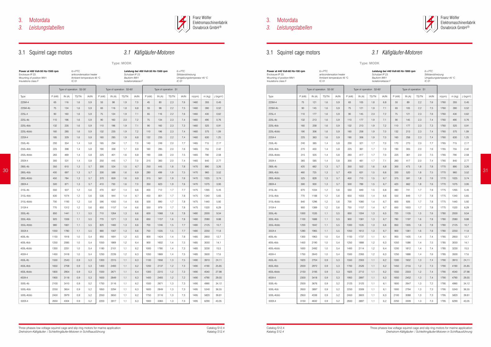
Power at 400 Volt-50 Hz-1500 rpm Enclosure IP 23Mounting of position IMV1Insulations class F
6 x PTCanticondensation heaterAmbient temperature 45 °CIC 01
Leistungbei400Volt-50Hz-1500rpm Schutzart IP 23Bauform IMV1Isolationsklasse F
6 x PTCStillstandsheizungUmgebungstemperatur 45 °CIC 01
Power at 440 Volt-60 Hz-100 rpm Enclosure IP 23Mounting of position IMV1Insulations class F
6 x PTCanticondensation heaterAmbient temperature 45 °CIC 01
Leistungbei440Volt-60Hz-1800rpm Schutzart IP 23Bauform IMV1Isolationsklasse F
6 x PTCStillstandsheizungUmgebungstempeatur 45 °CIC 01
3.1 Squirrel cage motors 3.1 Käfigläufer-Motoren 3.1 Squirrel cage motors 3.1 Käfigläufer-Motoren
Type: MODK Type: MODK
30 31

Three phases low voltage squirrel cage and slip ring motors for marine applicationDrehstrom-Käfigläufer- / Schleifringläufer-Motoren in Schiffsausführung
Catalog S12.4Katalog S12.4
Three phases low voltage squirrel cage and slip ring motors for marine applicationDrehstrom-Käfigläufer- / Schleifringläufer-Motoren in Schiffsausführung
Catalog S12.4Katalog S12.4
3. Motordata3. Leistungstabellen
3. Motordata3. Leistungstabellen
Type of operation S2-30‘ Type of operation S2-60‘ Type of operation S1
Type P ( kW) IN (A) TS/TN IA/IN P (kW) IN (A) TS/TN IA/IN P (kW) IN (A) TS/TN IA/IN n(rpm) m (kg) J (kgm²)
225L-6b 90 173 1,6 6,0 75 144 1,9 7,2 65 125 2,2 8,3 960 525 1,21
225L-6bb 105 202 1,6 6,0 90 173 1,9 7,0 75 144 2,2 8,4 960 565 1,41
225L-6bbb 115 221 1,6 6,0 100 192 1,8 6,9 82 158 2,2 8,4 960 595 1,55
225X-6 125 240 1,6 6,0 110 211 1,8 6,8 90 173 2,2 8,3 960 620 1,68
250L-6b 140 236 1,5 5,9 120 202 1,8 6,9 100 168 2,1 8,3 965 660 1,68
250L-6bb 170 286 1,5 5,9 140 236 1,8 7,2 120 202 2,1 8,4 965 710 1,99
250L-6bbb 200 337 1,5 5,9 170 286 1,8 6,9 145 244 2,1 8,1 965 765 2,33
250X-6 230 387 1,5 5,9 195 328 1,8 7,0 165 278 2,1 8,2 965 820 2,68
280L-6b 270 501 1,4 5,8 230 427 1,6 6,8 195 362 1,9 8,0 970 985 3,41
280L-6bb 295 547 1,4 5,8 250 464 1,7 6,8 210 390 2,0 8,1 970 1065 3,73
280L-6bbb 330 612 1,4 5,8 275 510 1,7 7,0 235 436 2,0 8,1 970 1130 4,18
280X-6 380 705 1,4 5,8 315 584 1,7 7,0 270 501 2,0 8,2 970 1210 4,81
315L-6b 400 802 1,3 5,7 335 672 1,6 6,8 285 572 1,8 8,0 975 1250 5,86
315L-6bb 450 903 1,3 5,7 375 752 1,6 6,8 315 632 1,9 8,1 975 1390 6,51
315L-6bbb 500 1003 1,3 5,7 420 842 1,5 6,8 355 712 1,8 8,0 975 1440 7,16
315X-6 550 1103 1,3 5,7 470 943 1,5 6,7 400 802 1,8 7,8 975 1510 7,91
355L-6b 630 1118 1,2 5,6 520 922 1,5 6,8 450 798 1,7 7,8 980 1875 10,25
355L-6bb 700 1242 1,2 5,6 600 1064 1,4 6,5 500 887 1,7 7,8 980 2040 11,17
355L-6bbb 770 1366 1,2 5,6 650 1153 1,4 6,6 550 976 1,7 7,8 980 2150 12,11
355X-6 840 1490 1,2 5,6 700 1242 1,4 6,7 600 1064 1,7 7,8 980 2280 13,6
400L-6b 900 1570 1,1 5,5 750 1308 1,3 6,6 630 1099 1,6 7,9 985 2650 17,71
400L-6bb 950 1657 1,1 5,5 800 1395 1,3 6,5 680 1186 1,5 7,7 985 2850 19,21
400L-6bbb 1025 1788 1,1 5,5 875 1526 1,3 6,4 730 1273 1,5 7,7 985 3050 21,22
400X-6 1125 1962 1,1 5,5 950 1657 1,3 6,5 800 1395 1,5 7,7 985 3250 24,14
450L-6b 1200 2059 1,0 5,5 1000 1716 1,2 6,6 850 1458 1,4 7,8 990 3510 27,61
450L-6bb 1350 2316 1,0 5,5 1125 1930 1,2 6,6 950 1630 1,4 7,8 990 3750 31,05
450L-6bbb 1470 2522 1,0 5,5 1250 2144 1,2 6,5 1050 1801 1,4 7,7 990 4050 33,82
450X-6 1600 2745 1,0 5,5 1350 2316 1,2 6,5 1150 1973 1,4 7,7 990 4220 36,82
500L-6b 1700 2869 0,9 5,5 1400 2362 1,1 6,7 1200 2025 1,3 7,8 995 4750 56,24
500L-6bb 1900 3206 0,9 5,5 1550 2616 1,1 6,7 1350 2278 1,3 7,7 995 5100 61,68
500L-6bbb 2100 3544 0,9 5,5 1700 2869 1,1 6,8 1500 2531 1,3 7,7 995 5400 67,16
500X-6 2300 3881 0,9 5,5 1900 3206 1,1 6,7 1650 2784 1,3 7,7 995 5650 73,56
560L-6b 2400 3984 0,9 5,5 2000 3320 1,1 6,6 1700 2822 1,3 7,8 995 6210 96,34
560L-6bb 2600 4316 0,9 5,5 2150 3569 1,1 6,7 1850 3071 1,3 7,7 995 6730 104,3
560L-6bbb 2800 4648 0,9 5,5 2300 3818 1,1 6,7 2000 3320 1,3 7,7 995 7250 112,4
Type of operation S2-30‘ Type of operation S2-60‘ Type of operation S1
Type P (kW) IN (A) TS/TN IA/IN P (kW) IN (A) TS/TN IA/IN P (kW) IN (A) TS/TN IA/IN n(rpm) m (kg) J (kgm²)
225L-6b 105 183 1,6 6,0 90 157 1,9 7,0 75 130 2,2 8,4 1160 525 1,21
225L-6bb 120 209 1,6 6,0 100 174 1,9 7,2 85 148 2,3 8,5 1160 565 1,41
225L-6bbb 132 230 1,6 6,0 110 191 1,9 7,2 95 165 2,2 8,3 1160 595 1,55
225X-6 145 252 1,6 6,0 125 217 1,9 7,0 105 183 2,2 8,3 1160 620 1,68
250L-6b 170 259 1,5 5,9 140 214 1,8 7,2 120 183 2,1 8,4 1165 660 1,68
250L-6bb 195 297 1,5 5,9 165 252 1,8 7,0 140 214 2,1 8,2 1165 710 1,99
250L-6bbb 230 351 1,5 5,9 200 305 1,7 6,8 170 259 2,0 8,0 1165 765 2,33
250X-6 275 420 1,5 5,9 230 351 1,8 7,1 195 297 2,1 8,3 1165 820 2,68
280L-6b 320 538 1,4 5,8 275 462 1,6 6,7 230 386 1,9 8,1 1170 985 3,41
280L-6bb 350 588 1,4 5,8 295 496 1,7 6,9 250 420 2,0 8,1 1170 1065 3,73
280L-6bbb 385 647 1,4 5,8 325 545 1,7 6,9 275 462 2,0 8,1 1170 1130 4,18
280X-6 440 739 1,4 5,8 370 622 1,7 6,9 315 529 2,0 8,1 1170 1210 4,81
315L-6b 475 863 1,3 5,7 400 727 1,5 6,8 335 608 1,8 8,1 1175 1250 5,86
315L-6bb 525 954 1,3 5,7 450 817 1,5 6,7 375 681 1,8 8,0 1175 1390 6,51
315L-6bbb 600 1090 1,3 5,7 500 908 1,6 6,8 425 772 1,8 8,0 1175 1440 7,16
315X-6 650 1181 1,3 5,7 550 999 1,5 6,7 475 863 1,8 7,8 1175 1510 7,91
355L-6b 730 1173 1,2 5,6 600 964 1,5 6,8 520 835 1,7 7,9 1180 1875 10,25
355L-6bb 850 1365 1,2 5,6 700 1124 1,5 6,8 600 964 1,7 7,9 1180 2040 11,17
355L-6bbb 920 1478 1,2 5,6 770 1237 1,4 6,7 650 1044 1,7 7,9 1180 2150 12,11
355X-6 1000 1606 1,2 5,6 820 1317 1,5 6,8 700 1124 1,7 8,0 1180 2280 13,6
400L-6b 1050 1658 1,1 5,5 900 1422 1,3 6,4 750 1185 1,5 7,7 1185 2650 17,71
400L-6bb 1120 1769 1,1 5,5 950 1501 1,3 6,5 800 1264 1,5 7,7 1185 2850 19,21
400L-6bbb 1200 1895 1,1 5,5 1000 1580 1,3 6,6 850 1343 1,6 7,8 1185 3050 21,22
400X-6 1350 2132 1,1 5,5 1120 1769 1,3 6,6 950 1501 1,6 7,8 1185 3250 24,14
450L-6b 1400 2175 1,0 5,5 1200 1864 1,2 6,4 1000 1553 1,4 7,7 1190 3510 27,61
450L-6bb 1575 2447 1,0 5,5 1325 2058 1,2 6,5 1125 1748 1,4 7,7 1190 3750 31,05
450L-6bbb 1750 2718 1,0 5,5 1475 2291 1,2 6,5 1250 1942 1,4 7,7 1190 4050 33,82
450X-6 1900 2952 1,0 5,5 1600 2485 1,2 6,5 1350 2097 1,4 7,7 1190 4220 36,82
500L-6b 2000 3056 0,9 5,5 1675 2559 1,1 6,6 1425 2177 1,3 7,7 1195 4750 56,24
500L-6bb 2150 3285 0,9 5,5 1830 2796 1,1 6,5 1550 2368 1,2 7,6 1195 5100 61,68
500L-6bbb 2450 3744 0,9 5,5 2050 3132 1,1 6,6 1750 2674 1,3 7,7 1195 5400 67,16
500X-6 2650 4049 0,9 5,5 2250 3438 1,1 6,5 1900 2903 1,3 7,7 1195 5650 73,56
560L-6b 2800 4209 0,9 5,5 2350 3533 1,1 6,6 2000 3006 1,3 7,7 1195 6210 96,34
560L-6bb 3000 4510 0,9 5,5 2520 3788 1,1 6,5 2150 3232 1,3 7,7 1195 6730 104,3
560L-6bbb 3250 4886 0,9 5,5 2750 4134 1,1 6,5 2350 3533 1,2 7,6 1195 7250 112,4
Power at 400 Volt-50 Hz-1000 rpm Enclosure IP 23Mounting of position IMV1Insulations class F
6 x PTCanticondensation heaterAmbient temperature 45 °CIC 01
Leistungbei400Volt-50Hz-1000rpm Schutzart IP 23Bauform IMV1Isolationsklasse F
6 x PTCStillstandsheizungUmgebungstemperatur 45 °CIC 01
Power at 440 Volt-60 Hz-1200 rpm Enclosure IP 23Mounting of position IMV1Insulations class F
6 x PTCanticondensation heaterAmbient temperature 45 °CIC 01
Leistungbei440Volt-60Hz-1200rpm Schutzart IP 23Bauform IMV1Isolationsklasse F
6 x PTCStillstandsheizungUmgebungstemperatur 45 °CIC 01
3.1 Squirrel cage motors 3.1 Käfigläufer-Motoren 3.1 Squirrel cage motors 3.1 Käfigläufer-Motoren
Type: MODK Type: MODK
32 33

Three phases low voltage squirrel cage and slip ring motors for marine applicationDrehstrom-Käfigläufer- / Schleifringläufer-Motoren in Schiffsausführung
Catalog S12.4Katalog S12.4
Three phases low voltage squirrel cage and slip ring motors for marine applicationDrehstrom-Käfigläufer- / Schleifringläufer-Motoren in Schiffsausführung
Catalog S12.4Katalog S12.4
3. Motordata3. Leistungstabellen
3. Motordata3. Leistungstabellen
Type of operation S2-30‘ Type of operation S2-60‘ Type of operation S1
Type P (kW) IN (A) U02 I2 P (kW) IN (A) U02 I2 P (kW) IN (A) U02 I2 n(rpm) m (kg) J (kgm²)
200L-4 45 83 405 71 40 74 405 63 35 65 405 55 1455 310 0,39
200L-4b 55 102 495 71 48 89 495 62 41 76 495 53 1455 355 0,44
200L-4bb 60 111 555 69 52 97 555 60 45 84 555 53 1455 380 0,48
200L-4bbb 65 120 595 70 57 105 595 61 50 93 595 54 1455 415 0,51
225L-4 75 136 480 100 65 118 480 87 55 100 480 73 1460 455 0,72
225L-4b 85 154 555 98 75 136 555 86 65 118 555 75 1460 500 0,81
225L-4bb 95 172 610 99 85 154 610 89 70 127 610 73 1460 560 0,91
225L-4bbb 105 190 670 100 90 163 670 86 80 144 670 76 1460 620 1,01
250L-4 130 230 580 142 115 204 580 126 100 177 580 109 1470 730 1,24
250L-4b 150 266 670 142 130 231 670 124 110 195 670 104 1470 775 1,43
250L-4bb 170 301 725 149 150 266 725 131 132 234 725 116 1470 810 1,61
250L-4bbb 200 354 785 162 175 310 785 141 160 283 785 129 1470 890 1,86
280L-4 250 433 660 239 215 372 660 206 190 329 660 182 1475 1030 2,96
280L-4b 300 520 685 276 260 450 685 240 225 390 685 207 1475 1090 3,18
280L-4bb 340 589 720 298 300 520 720 263 250 433 720 219 1475 1150 3,41
280L-4bbb 385 667 695 350 335 580 695 304 285 494 695 259 1475 1260 3,71
315L-4 400 678 600 418 350 593 600 366 300 509 600 314 1480 1440 4,88
315L-4b 440 746 675 409 385 653 675 358 330 559 675 307 1480 1525 5,31
315L-4bb 480 814 770 391 410 695 770 334 360 610 770 293 1480 1615 5,97
315L-4bbb 530 898 695 479 460 780 695 415 400 678 695 361 1480 1790 6,63
355L-4 560 929 640 546 490 813 640 478 420 697 640 410 1485 1920 9,45
355L-4b 610 1012 695 548 530 880 695 476 450 747 695 404 1485 2100 10,4
355L-4bb 670 1112 760 550 580 962 760 476 500 829 760 411 1485 2240 11,2
355L-4bbb 730 1211 830 549 630 1045 830 474 550 912 830 414 1485 2320 12,6
400L-4 770 1257 755 633 670 1093 755 551 580 947 755 477 1490 2750 17,9
400L-4b 850 1388 855 617 740 1208 855 537 650 1061 855 472 1490 2910 18,8
400L-4bb 950 1551 955 618 830 1355 955 540 730 1192 955 475 1490 3130 20,1
400L-4bbb 1100 1796 1080 632 950 1551 1080 546 830 1355 1080 477 1490 3300 22,2
Type of operation S2-30‘ Type of operation S2-60‘ Type of operation S1
Type P (kW) IN (A) U02 I2 P (kW) IN (A) U02 I2 P (kW) IN (A) U02 I2 n(rpm) m (kg) J (kgm²)
200L-4 55 92 445 79 45 75 445 65 40 67 445 58 1755 310 0,39
200L-4b 62 104 545 73 55 92 545 65 47 79 545 55 1755 355 0,44
200L-4bb 75 126 610 79 65 109 610 68 55 92 610 58 1755 380 0,48
200L-4bbb 80 134 655 78 70 117 655 69 60 101 655 59 1755 415 0,51
225L-4 85 139 525 103 75 123 525 91 65 107 525 79 1760 455 0,72
225L-4b 100 164 610 105 85 139 610 89 75 123 610 78 1760 500 0,81
225L-4bb 110 180 670 105 100 164 670 95 85 139 670 81 1760 560 0,91
225L-4bbb 125 205 735 108 110 180 735 95 95 156 735 82 1760 620 1,01
250L-4 150 241 635 150 132 212 635 132 115 184 635 115 1770 730 1,24
250L-4b 175 281 735 151 150 241 735 129 132 212 735 114 1770 775 1,43
250L-4bb 210 337 795 168 185 297 795 148 160 257 795 128 1770 810 1,61
250L-4bbb 250 401 765 207 220 353 765 182 190 305 765 158 1770 890 1,86
280L-4 290 456 725 253 250 392 725 218 220 345 725 191 1775 1030 2,96
280L-4b 340 533 755 284 300 471 755 251 260 408 755 217 1775 1090 3,18
280L-4bb 380 596 790 304 330 518 790 264 290 455 790 232 1775 1150 3,41
280L-4bbb 430 675 765 355 380 595 765 313 330 518 765 272 1775 1260 3,71
315L-4 460 706 660 437 400 614 660 380 350 537 660 333 1780 1440 4,88
315L-4b 515 790 745 434 450 691 745 379 390 599 745 329 1780 1525 5,31
315L-4bb 560 860 845 416 490 752 845 364 425 652 845 316 1780 1615 5,97
315L-4bbb 620 952 765 509 540 829 765 443 470 721 765 386 1780 1790 6,63
355L-4 660 991 705 584 575 864 705 509 500 751 705 443 1785 1920 9,45
355L-4b 700 1052 765 571 610 916 765 497 530 796 765 432 1785 2100 10,4
355L-4bb 780 1172 835 583 680 1022 835 508 590 886 835 441 1785 2240 11,2
355L-4bbb 860 1292 915 587 750 1127 915 512 650 976 915 443 1785 2320 12,6
400L-4 900 1330 830 673 780 1153 830 583 680 1005 830 509 1790 2750 17,9
400L-4b 1000 1478 940 660 870 1286 940 575 760 1123 940 502 1790 2910 18,8
400L-4bb 1120 1656 1050 662 980 1449 1050 579 850 1256 1050 503 1790 3130 20,1
400L-4bbb 1250 1848 1185 655 1100 1626 1185 576 950 1404 1185 498 1790 3300 22,2
Power at 400 Volt-50 Hz-1500 rpm Enclosure IP 23Mounting of position IMV1Insulations class F
6 x PTCanticondensation heaterAmbient temperature 45 °CIC 01
Leistungbei400Volt-50Hz-1500rpm Schutzart IP 23Bauform IMV1Isolationsklasse F
6 x PTCStillstandsheizungUmgebungstemperatur 45 °CIC 01
Power at 440 Volt-60 Hz-1800 rpm Enclosure IP 23Mounting of position IMV1Insulations class F
6 x PTCanticondensation heaterAmbient temperature 45 °CIC 01
Leistungbei440Volt-60Hz-1800rpm Schutzart IP 23Bauform IMV1Isolationsklasse F
6 x PTCStillstandsheizungUmgebungstemperatur 45 °CIC 01
3.2 Slip ring motors 3.2 Schleifringläufer-Motoren 3.2 Slip ring motors 3.2 Schleifringläufer-Motoren
Type: MSODK Type: MSODK
34 35

Three phases low voltage squirrel cage and slip ring motors for marine applicationDrehstrom-Käfigläufer- / Schleifringläufer-Motoren in Schiffsausführung
Catalog S12.4Katalog S12.4
Three phases low voltage squirrel cage and slip ring motors for marine applicationDrehstrom-Käfigläufer- / Schleifringläufer-Motoren in Schiffsausführung
Catalog S12.4Katalog S12.4
3. Motordata3. Leistungstabellen
3. Motordata3. Leistungstabellen
Type of operation S2-30‘ Type of operation S2-60‘ Type of operation S1
Type P (kW) IN (A) U02 I2 P (kW) IN (A) U02 I2 P (kW) IN (A) U02 I2 n(rpm) m (kg) J (kgm²)
225L-6 45 87 335 87 40 78 335 77 35 68 335 68 965 445 1,01
225L-6b 55 107 405 88 48 93 405 77 42 82 405 67 965 465 1,13
225L-6bb 65 126 480 88 55 107 480 74 50 97 480 68 965 490 1,28
225L-6bbb 75 146 525 93 65 126 525 80 60 117 525 74 965 540 1,38
250L-6 90 171 510 112 80 152 510 100 70 133 510 87 970 665 1,54
250L-6b 110 209 620 113 95 180 620 97 85 161 620 87 970 760 1,99
250L-6bb 132 251 720 116 115 218 720 101 100 190 720 88 970 840 2,26
250L-6bbb 150 285 790 120 132 251 790 106 115 218 790 92 970 895 2,59
280L-6 160 297 535 190 140 260 535 166 120 223 535 142 975 975 3,14
280L-6b 190 352 640 188 165 306 640 164 145 269 640 144 975 1070 3,53
280L-6bb 220 408 620 225 190 352 620 194 165 306 620 169 975 1135 4,14
280L-6bbb 250 464 695 228 210 390 695 192 190 352 695 173 975 1210 4,77
315L-6 280 508 555 317 240 435 555 271 210 381 555 237 980 1505 6,95
315L-6b 320 580 625 321 280 508 625 281 240 435 625 241 980 1585 7,43
315L-6bb 360 653 705 320 315 571 705 280 270 490 705 240 980 1680 8,36
315L-6bbb 400 726 790 318 350 635 790 278 300 544 790 238 980 1790 9,28
355L-6 450 798 550 508 390 692 550 440 340 603 550 384 985 2020 12,1
355L-6b 500 887 610 509 435 772 610 443 380 674 610 387 985 2185 13,2
355L-6bb 550 976 670 510 480 851 670 445 410 727 670 380 985 2330 14,8
355L-6bbb 600 1064 730 510 520 922 730 442 450 798 730 383 985 2410 16,4
400L-6 620 1076 610 628 540 937 610 547 470 816 610 476 990 2690 23,9
400L-6b 680 1180 680 618 590 1024 680 536 510 885 680 463 990 2860 26,7
400L-6bb 750 1301 760 609 650 1128 760 528 570 989 760 463 990 3025 31,1
400L-6bbb 830 1440 830 618 720 1249 830 536 630 1093 830 469 990 3250 34,3
450L-6 850 1443 715 730 740 1256 715 636 650 1104 715 558 995 3850 44,2
450L-6b 920 1562 805 702 800 1358 805 610 700 1188 805 534 995 4175 49,6
450L-6bb 1000 1698 895 686 870 1477 895 597 750 1273 895 515 995 4450 59,3
450L-6bbb 1100 1868 940 719 950 1613 940 621 830 1409 940 542 995 4720 64,6
Type of operation S2-30‘ Type of operation S2-60‘ Type of operation S1
Type P (kW) IN (A) U02 I2 P (kW) IN (A) U02 I2 P (kW) IN (A) U02 I2 n(rpm) m (kg) J (kgm²)
225L-6 55 96 375 96 48 84 375 84 42 73 375 73 1165 445 1,01
225L-6b 65 113 455 93 58 100 455 82 50 87 455 71 1165 465 1,13
225L-6bb 80 139 540 96 70 122 540 84 60 104 540 72 1165 490 1,28
225L-6bbb 90 156 590 99 80 139 590 88 70 122 590 77 1165 540 1,38
250L-6 110 187 570 122 90 153 570 100 80 136 570 89 1170 665 1,54
250L-6b 132 224 695 121 115 195 695 105 100 170 695 91 1170 760 1,99
250L-6bb 160 272 805 126 132 224 805 104 120 204 805 95 1170 840 2,26
250L-6bbb 175 297 885 125 150 255 885 108 132 224 885 95 1170 895 2,59
280L-6 185 307 600 196 160 266 600 169 140 232 600 148 1175 975 3,14
280L-6b 220 365 715 195 195 324 715 173 170 282 715 151 1175 1070 3,53
280L-6bb 250 415 695 228 220 365 695 201 190 315 695 173 1175 1135 4,14
280L-6bbb 290 481 780 236 250 415 780 203 220 365 780 179 1175 1210 4,77
315L-6 330 536 620 334 290 471 620 294 250 406 620 253 1180 1505 6,95
315L-6b 370 601 700 332 320 519 700 287 280 455 700 251 1180 1585 7,43
315L-6bb 420 682 790 334 370 601 790 294 320 519 790 254 1180 1680 8,36
315L-6bbb 475 771 885 337 415 674 885 294 360 584 885 255 1180 1790 9,28
355L-6 530 842 615 535 460 730 615 464 400 635 615 404 1185 2020 12,1
355L-6b 580 921 685 526 500 794 685 453 440 699 685 399 1185 2185 13,2
355L-6bb 630 1000 750 521 550 873 750 455 480 762 750 397 1185 2330 14,8
355L-6bbb 700 1111 820 530 600 953 820 454 530 842 820 401 1185 2410 16,4
400L-6 730 1134 680 663 630 979 680 572 550 854 680 499 1190 2690 23,9
400L-6b 800 1243 760 650 690 1072 760 561 600 932 760 488 1190 2860 26,7
400L-6bb 900 1398 850 654 780 1212 850 567 680 1056 850 494 1190 3025 31,1
400L-6bbb 970 1507 930 644 840 1305 930 558 730 1134 930 485 1190 3250 34,3
450L-6 1030 1566 800 791 900 1368 800 691 780 1186 800 599 1195 3850 44,2
450L-6b 1100 1672 900 751 960 1459 900 655 840 1277 900 573 1195 4175 49,6
450L-6bb 1200 1824 995 741 1030 1566 995 636 900 1368 995 556 1195 4450 59,3
450L-6bbb 1300 1976 1055 757 1120 1703 1055 652 980 1490 1055 571 1195 4720 64,6
Power at 400 Volt-50 Hz-1000 rpm Enclosure IP 23Mounting of position IMV1Insulations class F
6 x PTCanticondensation heaterAmbient temperature 45 °CIC 01
Leistungbei400Volt-50Hz-1000rpm Schutzart IP 23Bauform IMV1Isolationsklasse F
6 x PTCStillstandsheizungUmgebungstemperatur 45 °CIC 01
Power at 440 Volt-60 Hz-1200 rpm Enclosure IP 23Mounting of position IMV1Insulations class F
6 x PTCanticondensation heaterAmbient temperature 45 °CIC 01
Powerat440Volt-60Hz-1200rpm Schutzart IP 23Bauform IMV1Isolationsklasse F
6 x PTCStillstandsheizungUmgebungstemperatur 45 °CIC 01
3.2 Slip ring motors 3.2 Schleifringläufer-Motoren 3.2 Slip ring motors 3.2 Schleifringläufer-Motoren
Type: MSODK Type: MSODK
36 37

DIMENSIONAL DRAWINGSMASSBLÄTTER

Three phases low voltage squirrel cage and slip ring motors for marine applicationDrehstrom-Käfigläufer- / Schleifringläufer-Motoren in Schiffsausführung
Catalog S12.4Katalog S12.4
Three phases low voltage squirrel cage and slip ring motors for marine applicationDrehstrom-Käfigläufer- / Schleifringläufer-Motoren in Schiffsausführung
Catalog S12.4Katalog S12.4
4. Dimensional drawings4. Maßblätter
4. Dimensional drawings4. Maßblätter
All dimensions are in mm / Alle Maße in Millimeter
Typea1 b1 c1 e1 f1 g g2 i1 k n1 q s1 d l u2 t s4
P N LA M T AC AD - L - - S D E F GA -
MDK 225S 450 350 16 400 5 448 345 140 810 8 432 18 60 140 18 64,2 M20
MDK 225M 450 350 16 400 5 448 345 140 850 8 450 18 60 140 18 64,2 M20
MDK 250M 550 450 22 500 5 498 375 140 920 8 485 18 65 140 18 69,0 M20
MDK 280S 550 450 22 500 5 558 425 140 1010 8 515 18 75 140 20 79,5 M20
MDK 280M 550 450 22 500 5 558 425 140 1060 8 530 18 75 140 20 79,5 M20
MDK 315S 660 550 25 600 6 628 485 170 1130 8 550 22 80 170 22 85,0 M20
MDK 315M 660 550 25 600 6 628 485 170 1170 8 575 22 80 170 22 85,0 M20
MDK 315M 660 550 25 600 6 628 485 170 1170 8 575 22 80 170 22 85,0 M20
MDK 315L 660 550 25 600 6 628 485 170 1220 8 625 22 80 170 22 85,0 M20
MDK 315X 660 550 25 600 6 628 485 170 1220 8 625 22 80 170 22 85,0 M20
All dimensions are in mm / Alle Maße in Millimeter
female thread DIN 332D
tolerance range shaft end DIN 748 page 3
n1=number of flange holes
flanges to DIN 42948
up to ∅ 55mm “k6“, over ∅ 55 mm “m6“
fitting key to DIN 6885 page 1
Innengewinde S4 nach DIN332D
Passungen für Wellenenden DIN 748 Bl. 3
n1=Anzahl der Flanschlöcher
Befestigungsflansche nach DIN 42948
bis ∅ 55 mm „k6“, über ∅ 55 mm „m6“
Passfeder nach DIN 6885 Bl. 1
Typea1 b1 c1 e1 f1 g g2 i1 k n1 q s1 d l u2 t s4
P N LA M T AC AD - L - - S D E F GA -
MDK 355L 800 680 25 740 6 708 525 170 1395 8 750 22 90 170 22 95,3 M24
MDK 355X 800 680 25 740 6 708 525 170 1395 8 750 22 90 170 22 95,3 M24
MDK 400L 1000 880 30 940 6 798 650 210 1530 8 845 22 100 210 28 106 M24
MDK 400L 1000 880 30 940 6 798 650 210 1530 8 845 22 100 210 28 106 M24
MDK 400X 1000 880 30 940 6 798 650 210 1530 8 845 22 100 210 28 106 M24
MDK 450L 1150 1000 30 1080 6 898 700 210 1670 8 1200 28 110 210 28 116 M24
MDK 450X 1150 1000 30 1080 6 898 700 210 1770 8 1250 28 110 210 28 116 M24
MDK 500L 1150 1000 30 1080 6 898 700 210 1880 8 1300 28 120 210 32 126 M24
MDK 500X 1150 1000 30 1080 6 898 700 210 1990 8 1350 28 120 210 32 126 M24
female thread DIN 332D
tolerance range shaft end DIN 748 page 3
n1=number of flange holes
flanges to DIN 42948
up to ∅ 55mm “k6“, over ∅ 55 mm “m6“
fitting key to DIN 6885 page 1
Innengewinde S4 nach DIN332D
Passungen für Wellenenden DIN 748 Bl. 3
n1=Anzahl der Flanschlöcher
Befestigungsflansche nach DIN 42948
bis ∅ 55 mm „k6“, über ∅ 55 mm „m6“
Passfeder nach DIN 6885 Bl. 1
Type of cooling IC 411self ventilated
Enclosure: IP 54Mounting: IM V1/IM B5
Kühlung IC 411 Eigenlüfter
Schutzart: IP 54Bauform: IM V1/IM B5
Type of cooling IC 411self ventilated
Enclosure: IP 54Mounting: IM V1/IM B5
Kühlung IC 411Eigenlüfter
Schutzart: IP 54Bauform: IM V1/IM B5
4.1 Squirrel cage motors 4.1 Käfigläufer-Motoren 4.1 Squirrel cage motors 4.1 Käfigläufer-Motoren
40 41

Three phases low voltage squirrel cage and slip ring motors for marine applicationDrehstrom-Käfigläufer- / Schleifringläufer-Motoren in Schiffsausführung
Catalog S12.4Katalog S12.4
Three phases low voltage squirrel cage and slip ring motors for marine applicationDrehstrom-Käfigläufer- / Schleifringläufer-Motoren in Schiffsausführung
Catalog S12.4Katalog S12.4
All dimensions are in mm / Alle Maße in Millimeter
female thread DIN 332D
tolerance range shaft end DIN 748 page 3
n1=number of flange holes
flanges to DIN 42948
up to ∅ 55mm “k6“, over ∅ 55 mm “m6“
fitting key to DIN 6885 page 1
Innengewinde S4 nach DIN332D
Passungen für Wellenenden DIN 748 Bl. 3
n1=Anzahl der Flanschlöcher
Befestigungsflansche nach DIN 42948
bis ∅ 55 mm „k6“, über ∅ 55 mm „m6“
Passfeder nach DIN 6885 Bl. 1
All dimensions are in mm / Alle Maße in Millimeter
Typea1 b1 c1 e1 f1 g g2 i1 k n1 q s1 d l u2 t s4
P N LA M T AC AD - L - - S D E F GA -
MDKO 160M / SFB10 350 250 13 300 5 350 245 110 675 4 290 18 42 110 12 45,0 M16
MDKO 160L / SFB10 350 250 13 300 5 350 245 110 720 4 315 18 42 110 12 45,0 M16
MDKO 180M / SFB16 350 250 13 300 5 350 335 110 750 4 325 18 48 110 14 51,5 M16
MDKO 180L / SFB16 350 250 13 300 5 350 335 110 790 4 345 18 48 110 14 51,5 M16
MDKO 200L / SFB25 400 300 15 350 5 350 325 110 845 4 395 18 55 110 16 59,0 M20
Typea1 b1 c1 e1 f1 g g2 i1 k n1 q s1 d l u2 t s4
P N LA M T AC AD - L - - S D E F GA -
MDKO 225S / SFB40 450 350 16 400 5 450 345 140 920 8 432 18 60 140 18 64,2 M20
MDKO 225M / SFB40 450 350 16 400 5 450 345 140 945 8 450 18 60 140 18 64,2 M20
MDKO 250M / SFB63 550 450 22 500 5 550 375 140 1020 8 515 18 65 140 18 69 M20
MDKO 280S / SFB100 550 450 22 500 5 550 425 140 1100 8 515 18 75 140 20 79,5 M20
MDKO 280M / SFB100 550 450 22 500 5 550 425 140 1150 8 530 18 75 140 20 79,5 M20
MDKO 315S / SFB160 660 550 25 600 6 660 485 170 1270 8 550 22 80 170 22 85,0 M20
MDKO 315M / SFB160 660 550 25 600 6 660 485 170 1320 8 575 22 80 170 22 85,0 M20
MDKO 315L / SFB160 660 550 25 600 6 660 485 170 1370 8 625 22 80 170 22 85,0 M20
MDKO 315X / SFB160 660 550 25 600 6 660 485 170 1370 8 625 22 80 170 22 85,0 M20
MDKO 355L / SFB250 800 680 25 740 6 800 525 170 1480 8 685 22 90 170 25 95,3 M24
MDKO 355X / SFB250 800 680 25 740 6 800 525 210 1480 8 685 22 100 210 25 106 M24
female thread DIN 332D
tolerance range shaft end DIN 748 page 3
n1=number of flange holes
flanges to DIN 42948
up to ∅ 55mm “k6“, over ∅ 55 mm “m6“
fitting key to DIN 6885 page 1
Innengewinde S4 nach DIN332D
Passungen für Wellenenden DIN 748 Bl. 3
n1=Anzahl der Flanschlöcher
Befestigungsflansche nach DIN 42948
bis ∅ 55 mm „k6“, über ∅ 55 mm „m6“
Passfeder nach DIN 6885 Bl. 1
4. Dimensional drawings4. Maßblätter
4. Dimensional drawings4. Maßblätter
with brakeType of cooling IC 410without ventilation
Enclosure: IP 56Mounting: IM V1/IM B5
mit angebauter Haltebremse Kühlung IC 410 unbelüftet
Schutzart: IP 56Bauform: IM V1/IM B5
with brakeType of cooling IC 410without ventilation
Enclosure: IP 56Mounting: IM V1/IM B5
mit angebauter Haltebremse Kühlung IC 410 unbelüftet
Schutzart: IP 56Bauform: IM V1/IM B5
4.1 Squirrel cage motors 4.1 Käfigläufer-Motoren 4.1 Squirrel cage motors 4.1 Käfigläufer-Motoren
42 43

Three phases low voltage squirrel cage and slip ring motors for marine applicationDrehstrom-Käfigläufer- / Schleifringläufer-Motoren in Schiffsausführung
Catalog S12.4Katalog S12.4
Three phases low voltage squirrel cage and slip ring motors for marine applicationDrehstrom-Käfigläufer- / Schleifringläufer-Motoren in Schiffsausführung
Catalog S12.4Katalog S12.4
All dimensions are in mm / Alle Maße in Millimeter All dimensions are in mm / Alle Maße in Millimeter
female thread DIN 332D
tolerance range shaft end DIN 748 page 3
n1=number of flange holes
flanges to DIN 42948
up to ∅ 55mm “k6“, over ∅ 55 mm “m6“
fitting key to DIN 6885 page 1
Innengewinde S4 nach DIN332D
Passungen für Wellenenden DIN 748 Bl. 3
n1=Anzahl der Flanschlöcher
Befestigungsflansche nach DIN 42948
bis ∅ 55 mm „k6“, über ∅ 55 mm „m6“
Passfeder nach DIN 6885 Bl. 1
female thread DIN 332D
tolerance range shaft end DIN 748 page 3
n=number of flange holes
flanges to DIN 42948
up to ∅ 55mm “k6“, over ∅ 55 mm “m6“
fitting key to DIN 6885 page 1
Innengewinde S4 nach DIN332D
Passungen für Wellenenden DIN 748 Bl. 3
n=Anzahl der Flanschlöcher
Befestigungsflansche nach DIN 42948
bis ∅ 55 mm „k6“, über ∅ 55 mm „m6“
Passfeder nach DIN 6885 Bl. 1
Typea1 b1 c1 e1 f1 g g2 i1 k n1 q s d l u2 t s4
P N LA M T AC AD - L - - S D E F GA -
MODK 225M 550 450 22 500 5 448 395 140 935 8 445 18 65 140 18 69,0 M20
MODK 225L 550 450 22 500 5 448 395 140 1020 8 463 18 65 140 18 69,0 M20
MODK 225X 550 450 22 500 5 448 395 140 1095 8 490 18 65 140 18 69,0 M20
MODK 250L-b 660 550 25 600 6 498 440 140 1140 8 501 22 75 140 20 79,5 M20
MODK 250X 660 550 25 600 6 498 440 140 1170 8 566 22 75 140 20 79,5 M20
MODK 280L 660 550 25 600 6 498 480 170 1180 8 580 22 80 170 22 85,5 M20
MODK 280X 660 550 25 600 6 498 480 170 1300 8 655 22 80 170 22 85,5 M20
MODK 315L 800 680 25 740 6 700 515 170 1280 8 655 22 90 170 25 95,3 M24
MODK 315X 800 680 25 740 6 700 515 170 1400 8 730 22 90 170 25 95,3 M24
Typea1 b1 c1 e1 f1 g g2 i1 k n1 q s d l u2 t s4
P N LA M T AC AD - L - - S D E F GA -
MODK 355L 1000 880 30 940 6 790 555 210 1410 8 839 22 100 210 28 106 M24
MODK 355X 1000 880 30 940 6 790 555 210 1610 8 940 22 100 210 28 106 M24
MODK 400L 1000 880 30 940 6 870 625 210 1680 8 885 22 110 210 28 116 M24
MODK 400X 1000 880 30 940 6 870 625 210 1750 8 960 22 110 210 28 116 M24
MODK 450L 1150 1000 30 1080 6 970 675 210 1850 8 910 28 120 210 32 127 M24
MODK 450X 1150 1000 30 1080 6 970 675 210 1900 8 940 28 120 210 32 127 M24
MODK 500L 1150 1000 30 1080 6 1080 735 210 1950 8 985 28 130 210 32 137 M24
MODK 500X 1150 1000 30 1080 6 1080 735 210 2000 8 1020 28 130 210 32 137 M24
4. Dimensional drawings4. Maßblätter
4. Dimensional drawings4. Maßblätter
Type of cooling IC 01self ventilated
Enclosure: IP 23Mounting: IM V1
Kühlung IC 01 Eigenlüfter
Schutzart: IP 23Bauform: IM V1
Type of cooling IC 01self ventilated
Enclosure: IP 23Mounting: IM V1
Kühlung IC 01 Eigenlüfter
Schutzart: IP 23Bauform: IM V1
4.1 Squirrel cage motors 4.1 Käfigläufer-Motoren 4.1 Squirrel cage motors 4.1 Käfigläufer-Motoren
44 45

Three phases low voltage squirrel cage and slip ring motors for marine applicationDrehstrom-Käfigläufer- / Schleifringläufer-Motoren in Schiffsausführung
Catalog S12.4Katalog S12.4
Three phases low voltage squirrel cage and slip ring motors for marine applicationDrehstrom-Käfigläufer- / Schleifringläufer-Motoren in Schiffsausführung
Catalog S12.4Katalog S12.4
All dimensions are in mm / Alle Maße in Millimeter
Typea1 b1 c1 e1 f1 g g2 i1 k n1 q s1 d l u2 t s4
P N LA M T AC AD - L - - S D E F GA -
MSODK 200L 450 350 22 400 5 448 310 140 1025 8 400 18 60 140 18 64,2 M20
MSODK 225L 550 450 22 500 5 498 395 140 1110 8 470 18 65 140 18 69,0 M20
MSODK 250L 660 550 25 600 6 558 440 140 1200 8 510 22 75 140 20 79,5 M20
MSODK 280L 660 550 25 600 6 628 480 170 1460 8 610 22 80 170 22 85,5 M20
MSODK 315L 800 680 25 740 6 698 515 170 1510 8 490 22 90 170 25 95,3 M20
MSODK 355L 1000 880 30 940 6 790 555 210 1860 8 800 22 100 210 28 106 M24
MSODK 400L 1000 880 30 940 6 870 625 210 1840 8 770 22 110 210 28 116 M24
MSODK 450L 1150 1000 30 1080 6 970 675 210 2000 8 840 28 120 210 32 127 M24
female thread DIN 332D
tolerance range shaft end DIN 748 page 3
n1=number of flange holes
flanges to DIN 42948
up to ∅ 55mm “k6“, over ∅ 55 mm “m6“
fitting key to DIN 6885 page 1
Innengewinde S4 nach DIN332D
Passungen für Wellenenden DIN 748 Bl. 3
n1=Anzahl der Flanschlöcher
Befestigungsflansche nach DIN 42948
bis ∅ 55 mm „k6“, über ∅ 55 mm „m6“
Passfeder nach DIN 6885 Bl. 1
4. Dimensional drawings4. Maßblätter
4. Dimensional drawings4. Maßblätter
4.2 Slip ring motors 4.2 Schleifringläufer-Motoren
Type of cooling IC 01self ventilated
Enclosure: IP 23Mounting: IM V1
Kühlung IC 01 Eigenlüfter
Schutzart: IP 23Bauform: IM V1
46 47

CONTACTKONTAKT

Three phases low voltage squirrel cage and slip ring motors for marine applicationDrehstrom-Käfigläufer- / Schleifringläufer-Motoren in Schiffsausführung
Catalog S12.4Katalog S12.4
Three phases low voltage squirrel cage and slip ring motors for marine applicationDrehstrom-Käfigläufer- / Schleifringläufer-Motoren in Schiffsausführung
Catalog S12.4Katalog S12.4
5. Contact5. Kontakt
5. Contact5. Kontakt
5.1 Contact persons 5.1 Ansprechpartner 5.2 Directions 5.2 Anfahrtsskizze
FranzWölferElektromaschinenfabrikOsnabrückGmbH
Industriestraße 1449082 Osnabrück
Telefon +49 (0) 541 / 990 22-0Telefax +49 (0) 541 / 990 22-22
E-Mail [email protected] www.woelfer-motoren.com
Klaus SprekelmeyerHead of Sales / Leitung [email protected] +49 (0) 541 / 990 22-33
Franz-Josef HemesathManaging Director / Geschäftsfü[email protected] +49 (0) 541 / 990 22-13
Dipl.-Kfm. Arnd L. FrauendorfAuthorized signatory / ProkuristDirector of Finance and Administration / Kaufmännische [email protected] +49 (0) 541 / 990 22-40
Dr.-Ing. Andreas HeimbrockTechnical Director / Technische [email protected] +49 (0) 541 / 990 22-6750 51

NotesNotizen
NotesNotizen

NotesNotizen
NotesNotizen

Franz Wölfer Elektromaschinenfabrik Osnabrück GmbH Postfach 4380 · 49033 Osnabrück · Industriestraße 14 · 49082 OsnabrückTelefon +49 (0) 541 / 990 22-0 · Telefax +49 (0) 541 / 990 22-22 [email protected] · www.woelfer-motoren.com