wm2015 conference, march 15 – 19, 2015, phoenix, arizona ... · waste was first observed on the...
TRANSCRIPT

WM2015 Conference, March 15 – 19, 2015, Phoenix, Arizona, USA
1
Hanford Double-Shell Tank AY-102 Radioactive Waste Leak Investigation Update – 15302
Dennis J. Washenfelder *, Jeremy M. Johnson ** * AEM Consulting LLC
** U. S. Department of Energy
ABSTRACT Tank AY-102 was the first of 28 double-shell radioactive waste storage tanks constructed at the U. S. Department of Energy’s Hanford Site, near Richland, WA. The tank was completed in 1970, and entered service in 1971. In August, 2012, an accumulation of material was discovered at two sites on the floor of the annulus that separates the primary tank from the secondary liner. The material was sampled and determined to originate from the primary tank. This paper summarizes the changes in leak behavior that have occurred during the past two years, inspections to determine the capability of the secondary liner to continue safely containing the leakage, and the initial results of testing to determine the leak mechanism. INTRODUCTION Tank AY-102 was the first of 28 double-shell radioactive waste storage tanks constructed at the U. S. Department of Energy’s Hanford Site, near Richland, WA. The tank consists of a buried steel primary tank and secondary liner enclosed in a concrete shell, a concrete foundation, and numerous at-grade pits and risers for accessing the tank and installing equipment (refer to Figure 1). The primary steel tank rests inside the secondary steel liner and is supported by an insulating refractory pad on the floor of the secondary liner. An annular space of 0.76 m3 (2.5 ft) is formed between the primary tank and secondary liner sides. The primary tank and annulus have separate ventilation systems, both of which are kept at pressures negative to the environment with the use of exhaust fans. Annulus ventilation air flowing through channels cut into the surface of the insulating refractory pad cools the primary tank bottom. Waste was first observed on the annulus floor of tank AY-102 in August, 2012, during a scheduled annulus video inspection. Small accumulations were visible near Riser 87 in the northwest tank quadrant and near Riser 83 in the southwest quadrant. These were not present during the last inspection conducted December, 2006 – January, 2007. The reported volume was estimated to be 0.15 – 0.26 m3 (40 – 70 gal) of drying material at the two sites and nearby air cooling channels in the insulating refractory pad. A sample of material taken from the Riser 83 accumulation site in September, 2012, was confirmed to be tank waste. A third accumulation site formed during February, 2014, near Riser 77 in the northeast quadrant. A leak assessment identified the probable cause of the leak as corrosion at high temperatures in a tank whose waste containment margins had been reduced by construction difficulties. Construction difficulties and trial-and-error repairs had left the primary tank bottom with residual stresses that could not be foreseen by the designers. These provided an opportunity for sustained corrosion to take place [1].

WM2015 Conference, March 15 – 19, 2015, Phoenix, Arizona, USA
2
While the leak assessment was underway, response efforts began in multiple areas:
• Evaluation of the other double-shell tanks for the presence of construction and operating conditions that may have contributed to the tank AY-102 failure;
• Preparation for removal of the waste from tank AY-102 to a sound double-shell tank; • Identification of the corrosion failure mechanism, and changes in the tank inspection
program needed to identify incipient tank failures.
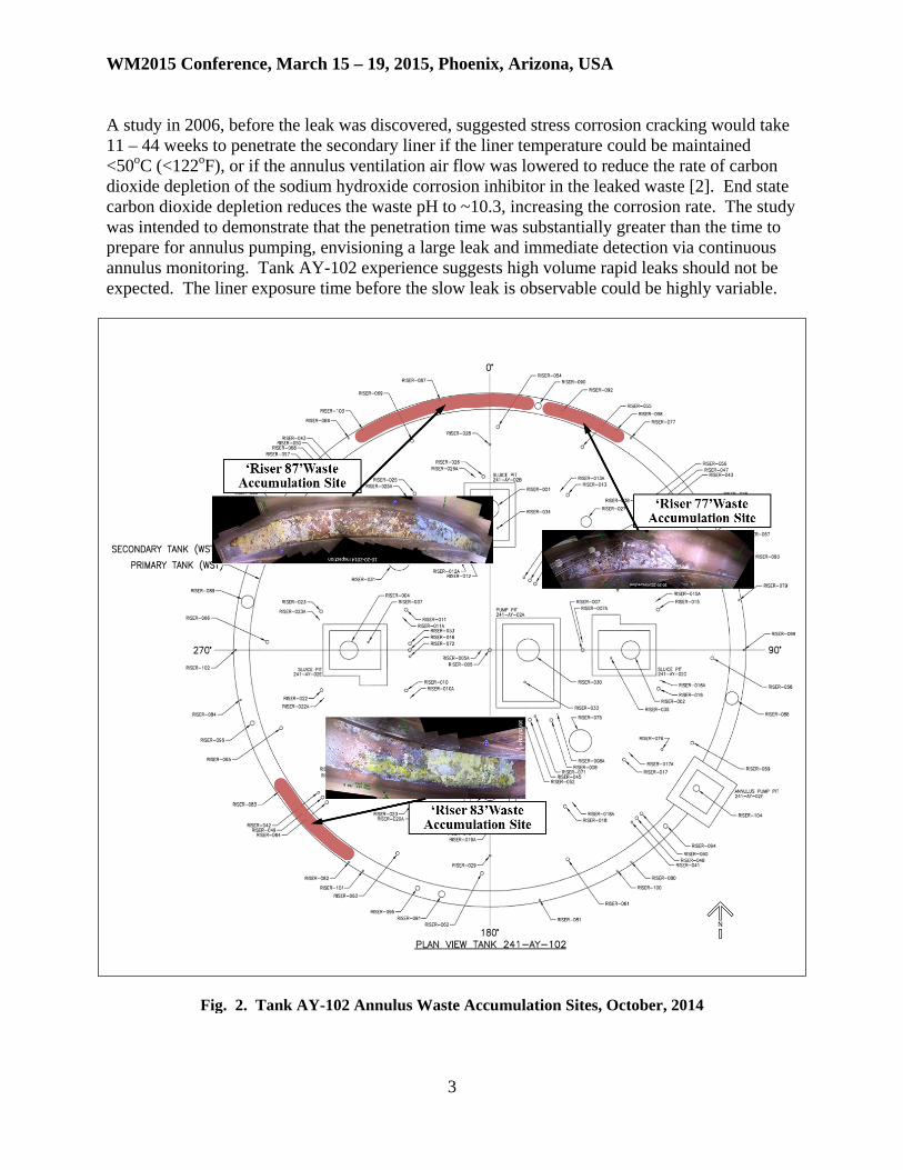
Fig. 1. Hanford Double-Shell Tank DISCUSSION After initial discovery of waste in the annulus the accumulation sites were observed twice weekly for additional change. The seepage of new material was episodic with periods when no change could be observed. In December, 2012, the observation frequency was reduced to once weekly, and in December, 2013, once every two weeks, which is the current frequency. As of October, 2014, the estimated leak volume accumulated on the tank annulus floor is 0.14 m3 (36.7 gal) (refer to Figure 2). The material accumulation rate for the period April – October, 2014 ranged from 0.002 m3/mo to 0.10 m3/mo (0.7 gal/mo to 2.7 gal/mo), with a decreasing trend. The average accumulation rate for the six month period was 0.005 m3/mo (1.4 gal/mo). There is no correlation with weather changes such as relative humidity or air temperature of the annulus ventilation air. There is no evidence of additional accumulation sites forming. Secondary Liner Lifetime Waste leaking from the primary tank is prevented from reaching the environment by the secondary steel liner. Experiments are underway to establish lifetime estimates based on the assumption that a secondary liner breach would be caused by either stress corrosion cracking or pitting.
WM2015 Conference, March 15 – 19, 2015, Phoenix, Arizona, USA
3
A study in 2006, before the leak was discovered, suggested stress corrosion cracking would take 11 – 44 weeks to penetrate the secondary liner if the liner temperature could be maintained <50oC (<122oF), or if the annulus ventilation air flow was lowered to reduce the rate of carbon dioxide depletion of the sodium hydroxide corrosion inhibitor in the leaked waste [2]. End state carbon dioxide depletion reduces the waste pH to ~10.3, increasing the corrosion rate. The study was intended to demonstrate that the penetration time was substantially greater than the time to prepare for annulus pumping, envisioning a large leak and immediate detection via continuous annulus monitoring. Tank AY-102 experience suggests high volume rapid leaks should not be expected. The liner exposure time before the slow leak is observable could be highly variable.
Fig. 2. Tank AY-102 Annulus Waste Accumulation Sites, October, 2014
WM2015 Conference, March 15 – 19, 2015, Phoenix, Arizona, USA
4
Thermocouple contact readings of the secondary liner floor directly below Riser 83 have measured the temperature as 37.9oC – 38.2 oC (100.2 oF – 100.4oF), consistent with the 2006 study assumption, and below the 50°C (122oF) threshold for onset of stress corrosion cracking. Mineral morphology of a waste sample taken from the leak accumulation site near Riser 83 noted the absence of the mineral trona ((Na3(CO3)(HCO3)•2H2O) indicating that carbon dioxide has not significantly depleted the sodium hydroxide inhibitor. A similar estimate for penetration time was prepared based on pitting growth rather than cracking using measured reductions found during tank AY-102 primary tank sidewall thinning inspections [3,4], Hanford single-shell tank liner failures [5], early U. S. Department of Energy Savannah River Site pitting experiments with non-inhibited simulated waste [6], and National Bureau of Standards corrosion measurements [7]. In the aggregate these concluded through-liner pitting would occur after about eight to 19 years. Cracking tests were initiated in Fiscal Year 2013 using metal coupons representing as-fabricated conditions of the secondary liner, including as-received, heat affected (weld) zones, and flame-heated fast-water quenched specimens representing efforts to remove secondary liner bottom distortions created during welding. Waste simulant compositions include as-leaked, and partially evaporated with and without carbon dioxide sodium hydroxide depletion. Cracking was not detected in any of the tests. In Fiscal Year 2014 cracking tests continued, pitting tests began, and corrosion testing was expanded to include “poultice” simulants representing waste in contact with the insulating refractory pad, and “puddle” simulants containing mixtures of poultice and saturated waste, representing drying waste on the floor of the secondary liner. Preliminary results show poultice simulant pitting rates of < 0.5 μM/yr (< 2E-05 in/yr) [8]. Double-Shell Tank Construction Reviews Following discovery of the tank AY-102 primary tank leak, extent of condition reviews began on the remaining 27 sound double-shell tanks. The reviews included 100% annulus video inspections of six double-shell tanks constructed immediately after tank AY-102, and extent of condition construction history reviews of all double-shell tanks. The annulus video inspections were completed between April, and June, 2013; none of the seven primary tanks showed evidence of leakage into the annulus; for areas previously inspected, visual comparisons found no significant changes in appearance indicating the material condition of the visible tank surfaces was stable. The extent of condition construction history reviews were prepared between May, 2013, and March, 2014, using records contained in 241, 0.03 m3 (1 ft3) records boxes obtained from the National Archives Regional Center in Seattle, Washington. The reviews sought information on construction difficulties similar to those experienced during tank AY-102 construction: secondary liner distortion during fabrication; insulating refractory cracking; primary tank bottom plate weld rejection, and primary tank post-weld stress relief difficulties. The results were published in five reports, each covering one tank farm, and a sixth report covering tank AY-101. In general most difficulties experienced during tank AY-102 construction either gradually diminished or were not found in the later tank farms due to design evolution and accumulated
WM2015 Conference, March 15 – 19, 2015, Phoenix, Arizona, USA
5
construction experience on-site. Where recurrence was evident, it most strongly correlated with selection of a new contractor for tank farm construction [9,10,11,12,13]. The results of the extent of condition review are discussed in WM2015 Conference Paper 15498 [14]. Double-Shell Tank Operating History Reviews During the tank AY-102 formal leak investigation historical sample analyses were reviewed to determine the susceptibility of the primary tank to waste corrosion. However the investigation did not consider the timeliness of efforts to mitigate out-of-corrosion specification waste throughout the tank’s operating life. In some cases there were significant lapses between discovery of the out-of-specification condition and adding corrosion inhibiting chemicals needed to return the waste to in-specification condition. These lapses were evaluated during June – August, 2014, when prototype sampling and corrosion mitigation histories were prepared for four double-shell tanks, including tank AY-102 [15]. The original corrosion specifications for waste in the 241-AY Farm required the waste pH to be between 8 and 10 [16]. The first major change in chemistry specifications occurred in 1983. Laboratory work performed at the Pacific Northwest National Laboratory and at the Savannah River National Laboratory, led to the establishment of present waste chemistry controls to minimize DST corrosion and the risk of tank failure from general corrosion, pitting, or stress corrosion cracking [17,18]. The minimum pH was increased to 12 to control pitting, and hydroxide and nitrite concentrations added to prevent nitrate-induced stress corrosion cracking. It is important to note that the sampling and corrosion mitigation histories of the four tanks were prepared using the existing corrosion specification rather than the specification that was in use during the pre-1983 time period. Comparing the existing corrosion specification to tank AY-102 historical supernatant and sludge sample compositions indicated that the supernatant waste has been out-of-specification for 15.4 years, and the sludge waste out-of-specification for 15.9 years. In other words, since the tank was first placed in service at least a portion of the waste was outside of the existing corrosion specification about 37% of the time (refer to Figure 3). Tank AY-102 Leak Detection System Inspection Tank AY-102 is provided with a tertiary leak detection system consisting of a grooved drainage system embedded in the upper surface of the foundation and an ex-tank leak detection collection sump equipped with liquid level monitoring. The sump chronically accumulates liquid at a rate of 7.5 – 11 l/day (2 – 3 gal/day) and requires periodic pumping to prevent the liquid from backing up into the drainage grooves and wetting the bottom of the secondary liner. In June, 2013, during sump pumping a radiation dose was detected on the overground transfer hose. Contamination was discovered on the transfer pump when it was removed from the sump. Both readings were indicative of a waste leak. Further investigation tracking the decrease of the Cs-137:Sr-90 ratio and solution pH in samples from earlier pumpings concluded that the contamination source was not a tank leak [19]. This was confirmed in November, 2013, by a robotic inspection of the drain line between the collection sump and the foundation drainage system. The inspection showed that the majority of the drain was dry with debris collected in localized areas. There was no visual evidence of

WM2015 Conference, March 15 – 19, 2015, Phoenix, Arizona, USA
6
Fig. 3. Tank AY-102 Operating History
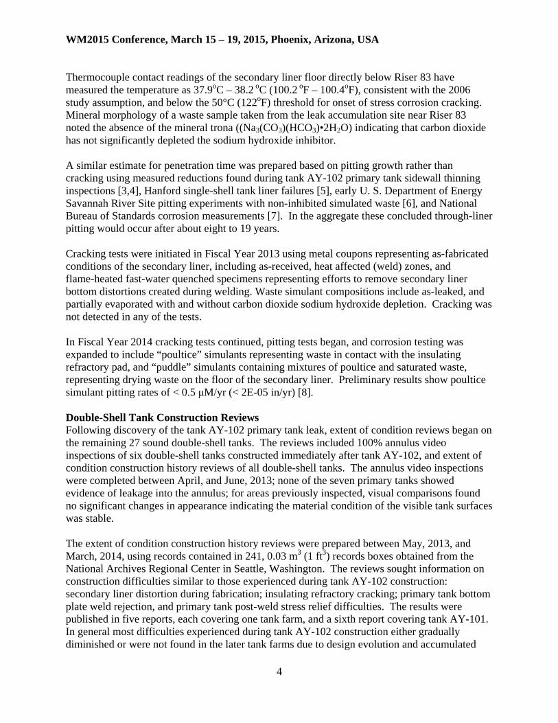
leakage, and the contamination levels were consistent with those found in the sump. The inspection covered the entire length of the drain line to within 2 m (7 ft) of the tank’s center before high-centering on debris (refer to Figure 4) [20]. The water accumulation in the sump is believed to result from differential air pressure across the slide plates separating the tank’s concrete sidewall from its foundation. The differential pressure from the annulus ventilation system extracts soil moisture across the slide plate interface where it collects in the foundation drainage grooves and drains to the sump. The origin of soil moisture is rainfall and snowmelt that wicks down the outside of the tank and gathers at the slide plate location. The slide plate design used in tank AY-102 is unique to the early double-shell tanks. Later tanks used a modified design and do not experience a similar water accumulation. Waste Retrieval Preparation On March 24, 2014, the State of Washington, Department of Ecology issued Administrative Order No. 10618 requiring the U. S. Department of Energy and Washington River Protection Solutions LLC to complete actions needed to remove the waste stored in tank AY-102. The administrative order was appealed, and then resolved through a settlement agreement approved September 29, 2014 [21]. The settlement agreement specifies leak monitoring requirements and waste retrieval completion dates.
WM2015 Conference, March 15 – 19, 2015, Phoenix, Arizona, USA
7
Fig. 4. Tank AY-102 Leak Detection System Inspection, November, 2013 The agreement requires that the leak accumulation sites in the annulus, including any newly discovered sites, be monitored every two weeks; the entire annulus inspected every two months; the pH and the liquid level of the leak detection sump monitored monthly, and the liquid sampled whenever the leak detection sump is pumped. Sludge retrieval must be completed no later than March 4, 2017; in-tank inspection and determination of the cause of tank failure will follow afterwards. About 1624 m3 (429 kgal) of tank AY-102 supernatant will be transferred to tank AW-105 leaving a 999 m3 – 2.4 m (264 kgal – 96-in) deep liquid layer over the sludge while retrieval preparations are completed. Keeping a significant liquid layer over the sludge maintains a stable waste temperature thereby reducing the likelihood of increases in either flammable gas generation or metal corrosion rates. If all of the supernatant was removed and the annulus air cooling slots beneath the primary tank slowly blocked by residual drying supernatant, then the sludge would eventually reach 127oC (260oF), exceeding the 70oC (160oF) maximum allowable concrete dome temperature, and the 77oC (170oF) corrosion specification limit. The tank 177oC (350oF) structural analysis limit would not be exceeded. Thermal modeling indicates that temperature equilibrium would take at least a year [22]. Waste retrieval is complicated by Hanford’s limited remaining double-shell tank storage space. Double-shell tank capacity is 122 km3 (32,300 kgal); however existing waste inventory, restricted tank space, and emergency pumping space have committed all but 9,560 m3 (~2,500 kgal) (~8% of capacity) as of August, 2014. Retrieving tank AY-102 will draw down the available storage space by at least 3,179 m3 (~840 kgal), reducing operating flexibility and

WM2015 Conference, March 15 – 19, 2015, Phoenix, Arizona, USA
8
potentially affecting future single-shell tanks retrievals. Additionally, the 9,560 m3 (~2,500 kgal) is “distributed” tank space, meaning it is composed of small capacity increments. In order to complete the tank AY-102 sludge retrieval into tank AP-102, the intended receiver, 13 tank-to-tank transfers will be required, and three waste evaporator campaigns completed to recover tank space [23]. Further discussion of the planned retrieval activity is provided in WM2015 Conference Paper 15298 [24]. Sludge waste retrieval will use a continuous loop between tanks AY-102 and AP-102. The waste will be mobilized with four extended reach hydraulic sluicers driven by a high pressure slurry pump in tank AP-102. A transfer pump mounted in tank AY-102 will transfer the mobilized slurry to tank AP-102 where the sludge will settle before the clarified supernatant is recycled. The extended reach sluicers have nozzle pan and tilt motion capability on a movable boom to maneuver around the twenty-two 76 cm (30 in) diameter vertical airlift circulators suspended from the tank dome and spaced equidistant in two concentric circles with radii 4.4 m (14.5 ft) and 8.2 m (27 ft) from the center of the tank (refer to Figure 5).
Fig. 5. Tank AY-102 Interior with Airlift Circulators CONCLUSIONS Periodic visual inspection of the tank AY-102 annulus waste accumulation sites show that waste from the primary tank has continued to slowly accumulate at a rate of 0.005 m3/mo (1.4 gal/mo) based on the six-month period ending October, 2014. The total estimated volume at the end of the period was 0.14 m3 (36.7 gal). There is no evidence that the secondary liner has been breached allowing waste to enter the environment. The waste remaining in the primary tank is expected to be removed to sound double-shell tanks by March 4, 2017. Following discovery of the tank AY-102 primary tank leak, extent of condition reviews were completed on the sound double-shell tanks. In general most construction difficulties thought to contribute to the tank AY-102 failure either were diminished or were not found in the later tank

WM2015 Conference, March 15 – 19, 2015, Phoenix, Arizona, USA
9
farms. When recurrence was evident, it most strongly correlated with selection of a new contractor for tank construction. Laboratory work during the Fiscal Year 2013 – 2015 period is expected to identify the corrosion failure mechanism responsible for the tank AY-102 primary tank leak and to provide a technical basis for estimating the secondary liner’s lifetime in contact with tank waste. Meanwhile operating histories using historical sample results and a prototypical analysis template are being prepared for the sound double-shell tanks. Preliminary work indicates that some double-shell tanks have stored waste that does not meet current corrosion control specifications for as much as 37% of their operating life. REFERENCES
1. Engeman, J. K., Girardot, C. L., Harlow, D. G., and Rosenkrance, C. L., RPP-RPT-53793, 2012, Tank 241-AY-102 Leak Assessment Report, Rev. 0, Washington River Protection Solutions LLC, Richland, Washington 99352
2. Boomer, K. D., RPP-RPT-27062, 2006, Stress Corrosion Cracking Evaluation for the Liner Exposed to In-Specification Waste in a Double-Shell Tank Annulus, Rev. 0, CH2M HILL Hanford Group, Inc., Richland, Washington 99352
3. Jensen, C. E., HNF-4818, 1999, Final Results of Double-Shell Tank 241-AY-102 Ultrasonic Inspection, Rev. 0, Lockheed Martin Hanford Corporation, Richland, Washington 99352
4. Friberg, A., RPP-RPT-32137, 2007, Ultrasonic Inspection Results for Double-Shell Tank 241-AY-102 -- FY2007, Rev. 0, CH2M HILL Hanford Group, Inc., Richland, Washington 99352
5. Catlin, R. J., 1980, Assessment of the Surveillance Program of the High-Level Waste Storage Tanks at Hanford, U. S. Department of Energy, Washington, D. C.
6. Zapp, P. E., WSRC-TR-96-0024, Pitting Growth in Carbon Steel Exposed to Simulated Radioactive Waste, 1996, Westinghouse Savannah River Company, Aiken, South Carolina 29808
7. Romanoff, M., National Bureau of Standards Circular 579, 1957, Underground Corrosion, U. S. Department of Commerce, Washington, D. C.
8. Brossia, C. L., et al, RPP-RPT-56141, 2014, FY2013 DNV DST and SST Corrosion and Stress Corrosion Cracking Testing Report, Rev. 0, Det Norske Veritas (USA) Inc., Columbus, Ohio 43017
9. Barnes, T. J., Boomer, K. D., Gunter, J. R., and Reeploeg, G. E., RPP-RPT-54818, 2013, 241-AP Tank Farm Construction Extent of Condition Review of Tank Integrity, Rev. 0, Washington River Protection Solutions LLC, Richland, Washington 99352

WM2015 Conference, March 15 – 19, 2015, Phoenix, Arizona, USA
10
10. Barnes, T. J., and Gunter, J. R., RPP-RPT-54817, 2014, 241-AY-101 Tank Construction Extent of Condition Review of Tank Integrity, Rev. 0, Washington River Protection Solutions LLC, Richland, Washington 99352
11. Barnes, T. J., Gunter, J. R., and Reeploeg, G. E., RPP-RPT-55981, 2013, 241-AW Tank Farm Construction Extent of Condition Review of Tank Integrity, Rev. 0, Washington River Protection Solutions LLC, Richland, Washington 99352
12. Barnes, T. J., Gunter, J. R., and Reeploeg, G. E., RPP-RPT-55982, 2014, 241-AN Tank Farm Construction Extent of Condition Review of Tank Integrity, Rev. 0, Washington River Protection Solutions LLC, Richland, Washington 99352
13. Barnes, T. J., Gunter, J. R., and Reeploeg, G. E., RPP-RPT-55983, 2014, 241-AP Tank Farm Construction Extent of Condition Review of Tank Integrity, Rev. 0, Washington River Protection Solutions LLC, Richland, Washington 99352
14. Vallalta, C., 2014, Analysis of Tank Chemistry Compliance with Chemistry Specification in Double-Shell Tanks, Florida International University, Miami, Florida 33174
15. Venetz, T. J., et al, WM2015 Conference Paper 15498, 2015, Hanford Double-Shell Tank Extent-of-Condition Construction Review, Washington River Protection Solutions LLC, Richland, WA 99352
16. Hatch, P., and Oberg, G. C., ARH-205, 1967, Design Criteria PUREX AY Tank Farm, Atlantic Richfield Hanford Company, Richland, Washington 99352
17. Divine, J. R., et al, PNL-5488, 1985, Prediction Equations for Corrosion Rates of A-537 and A-516 Steels in Double Shell Slurry, Future PUREX, and Hanford Facilities Wastes, Pacific Northwest National Laboratory, Richland, Washington 99352
18. Ondrejcin, R. S., DP-1478, 1978, Prediction of Stress Corrosion of Carbon Steel by Nuclear Process Liquid Wastes, Savannah River National Laboratory, Aiken, South Carolina 29801
19. Sams, T. L., RPP-RPT-55939, 2013, Tank 241-AY-102 Secondary Liner Integrity Investigation Resolution, Rev. 0, Washington River Protection Solutions LLC, Richland, WA 99352
20. Vazquez, B. J., RPP-RPT-56464, 2014, 241-AY-102 Leak Detection Pit Drain Line Inspection Report, Rev. 0, Washington River Protection Solutions LLC, Richland, WA 99352

WM2015 Conference, March 15 – 19, 2015, Phoenix, Arizona, USA
11
21. Pollution Control Hearings Board State of Washington, PCHB No. 14-041c Settlement Agreement, Washington River Protection Solutions; and U. S. Department of Energy, Office of River Protection, Appellants, v. State of Washington, Department of Ecology, Respondent, dated September 29, 2014
22. Ogden, D. M., RPP-56864, 2014, Tank 241-AY-102 Thermal Evaluation of Supernatant Reduction, Rev. 0, John Marvin, Inc., Washington River Protection Solutions LLC, Richland, WA 99352
23. Guillot, S. P., RPP-PLAN-59931, 2014, AY-102 Recovery Project Waste Retrieval Work Plan, Rev. 2, Washington River Protection Solutions LLC, Richland, WA 99352
24. Certa, P. J., et al, WM2015 Conference Paper 15298, 2015, Disposition of Hanford Tank Waste Sludge from Tank 241-AY-102 and the 241-A/AX Farm Tanks, Washington River Protection Solutions LLC, Richland, WA 99352