wmap polarization: lessons learned (to date) gary hinshaw nasa/gsfc cmbpol study workshop u....
Post on 21-Dec-2015
214 views
TRANSCRIPT
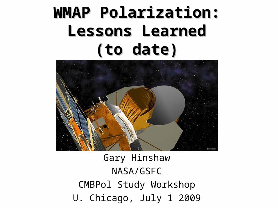
WMAP Polarization:WMAP Polarization:Lessons LearnedLessons Learned
(to date)(to date)
Gary Hinshaw
NASA/GSFC
CMBPol Study Workshop
U. Chicago, July 1 2009
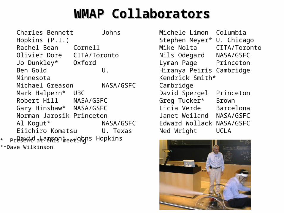
WMAP CollaboratorsWMAP CollaboratorsCharles Bennett Johns Hopkins (P.I.)Rachel Bean CornellOlivier Dore CITA/TorontoJo Dunkley* OxfordBen Gold U. MinnesotaMichael Greason NASA/GSFCMark Halpern* UBCRobert Hill NASA/GSFCGary Hinshaw* NASA/GSFCNorman Jarosik PrincetonAl Kogut* NASA/GSFCEiichiro Komatsu U. TexasDavid Larson* Johns Hopkins
Michele Limon ColumbiaStephen Meyer* U. ChicagoMike Nolta CITA/TorontoNils Odegard NASA/GSFCLyman Page PrincetonHiranya Peiris CambridgeKendrick Smith* CambridgeDavid Spergel PrincetonGreg Tucker* BrownLicia Verde BarcelonaJanet Weiland NASA/GSFCEdward Wollack NASA/GSFCNed Wright UCLA
**** Present at this meeting**Dave Wilkinson
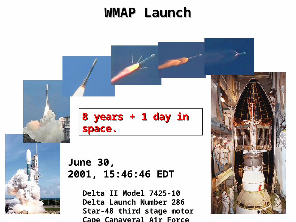
WMAP LaunchWMAP Launch
June 30, 2001, 15:46:46 EDT
Delta II Model 7425-10Delta Launch Number 286 Star-48 third stage motor Cape Canaveral Air Force StationPad SLC-17B
8 years + 1 day in space.8 years + 1 day in space.
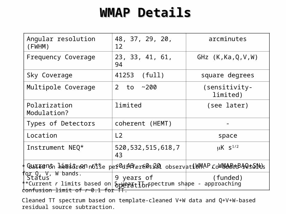
WMAP DetailsWMAP Details
Angular resolution (FWHM) 48, 37, 29, 20, 12 arcminutes
Frequency Coverage 23, 33, 41, 61, 94 GHz (K,Ka,Q,V,W)
Sky Coverage 41253 (full) square degrees
Multipole Coverage 2 to ~200 (sensitivity-limited)
Polarization Modulation? limited (see later)
Types of Detectors coherent (HEMT) -
Location L2 space
Instrument NEQ* 520,532,515,618,743 K s1/2
Current limit on r** <0.43, <0.20 (WMAP, WMAP+BAO+SN)
Status 9 years of operation (funded)
* Based on measured noise per differential observation. Co-added results for Q, V, W bands.
**Current r limits based on 5-year TT spectrum shape - approaching confusion limit of r~0.1 for TT.
Cleaned TT spectrum based on template-cleaned V+W data and Q+V+W-based residual source subtraction.
Data rate: 8 channels @ 128 ms, 8 @ 102.4 ms, 8 @ 76.8 ms, 16 @ 51.2 ms for 9 years.

WMAP Systematic Error TableWMAP Systematic Error Table
Systematic Effect Notes
Cross-polar beam E B sensitivity-limited
Polarization angle errors E B “
Pointing errors (on Q/U) E B “
Main beam asymmetry (before differencing)
dT B cross-polar?
Sidelobes dT B Barnes et al, ApJS, 148, 51 (2003)
Instrumental polarization dT B see 1/f noise
Relative calibration errors dT B subdominant to baseline errors
Pointing errors before differencing T B n/a
Gain drift before differencing T B see relative calibration
Optics and spillover T variations dTopt B Hinshaw et al., ApJS, submitted
Scan modulated cold stage variations dTCS B subdominant to optics variations
Band shape errors, including modulator effects
foregrounds B potentially significant to B modes,
modulate polarization angle
Others? “noise” E,B offset/baseline drifts
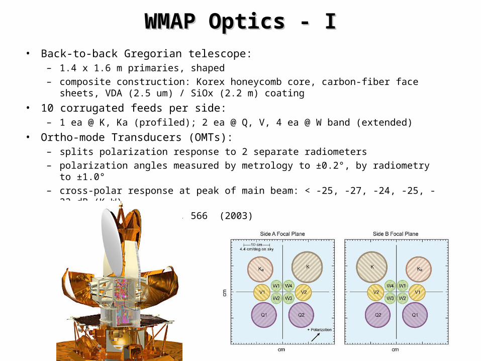
WMAP Optics - IWMAP Optics - I• Back-to-back Gregorian telescope:
– 1.4 x 1.6 m primaries, shaped– composite construction: Korex honeycomb core, carbon-fiber face sheets, VDA
(2.5 um) / SiOx (2.2 m) coating
• 10 corrugated feeds per side:– 1 ea @ K, Ka (profiled); 2 ea @ Q, V, 4 ea @ W band (extended)
• Ortho-mode Transducers (OMTs):– splits polarization response to 2 separate radiometers– polarization angles measured by metrology to ±0.2°, by radiometry to ±1.0°– cross-polar response at peak of main beam: < -25, -27, -24, -25, -22 dB (K-W)
Page et al., ApJ, 585, 566 (2003)
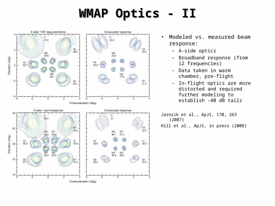
WMAP Optics - IIWMAP Optics - II
• Modeled vs. measured beam response:
– A-side optics– Broadband response (from
12 frequencies)– Data taken in warm
chamber, pre-flight– In-flight optics are more
distorted and required further modeling to establish -40 dB tails
Jarosik et al., ApJS, 170, 263 (2007)
Hill et al., ApJS, in press (2008)
WMAP Pointing AccuracyWMAP Pointing Accuracy• WMAP spacecraft frame primarily determined by star trackers
– Pointing reconstruction better than 5 arcsec in tracker frame.– Tracker mount flexes ~1 arcmin (on an annual time scale) relative to feed
frame due to thermal flexure of spacecraft top deck. Effect is modeled with an accuracy of ~0.1 arcmin.
– Instrument lines-of-sight measured with respect to spacecraft frame by centroiding Jupiter observations. Accuracy also ~0.1 arcmin per beam.
• Beams differenced in polarization measurement (radiometers 1 and 2) are always launched by the same feed, so are always relatively co-aligned.
In general, optical and pointing imperfections (which convert E mode to B mode) are subdominant for WMAP due to our relatively low signal-to-noise. We currently see no hint of B-modes after foreground cleaning. Larger concerns are aliasing of T to E, and accurate characterization of full errors at low-l.
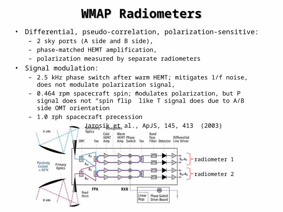
WMAP RadiometersWMAP Radiometers• Differential, pseudo-correlation, polarization-sensitive:
– 2 sky ports (A side and B side),– phase-matched HEMT amplification,– polarization measured by separate radiometers
• Signal modulation:– 2.5 kHz phase switch after warm HEMT; mitigates 1/f noise, does not modulate
polarization signal,– 0.464 rpm spacecraft spin; modulates polarization, but P signal does not “spin
flip” like T signal does due to A/B side OMT orientation– 1.0 rph spacecraft precession
Jarosik et al., ApJS, 145, 413 (2003)
radiometer 1
radiometer 2
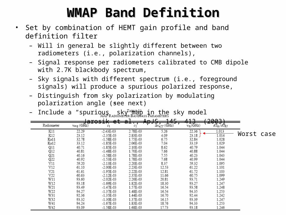
WMAP Band DefinitionWMAP Band Definition• Set by combination of HEMT gain profile and band definition filter
– Will in general be slightly different between two radiometers (i.e., polarization channels),
– Signal response per radiometers calibrated to CMB dipole with 2.7K blackbody spectrum,
– Sky signals with different spectrum (i.e., foreground signals) will produce a spurious polarized response,
– Distinguish from sky polarization by modulating polarization angle (see next)– Include a “spurious” sky map in the sky model
Jarosik et al., ApJS, 145, 413 (2003)
Worst case
WMAP Polarization ModulationWMAP Polarization Modulation
More details please...

WMAP Scan Strategy - IWMAP Scan Strategy - I
Not to scale:Earth — L2 distance is 1% of Sun — Earth Distance
Earth
Sun
MAP at L2
1 Day
3 Months
6 Months - full sky coverage
129 sec. (0.464rpm) Spin
22.5° half-angle1 hour precession cone
A-side line of site
B-side line of site
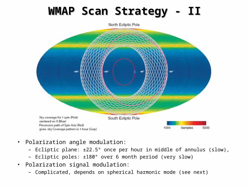
WMAP Scan Strategy - IIWMAP Scan Strategy - II
• Polarization angle modulation:– Ecliptic plane: ±22.5° once per hour in middle of annulus (slow),– Ecliptic poles: ±180° over 6 month period (very slow)
• Polarization signal modulation:– Complicated, depends on spherical harmonic mode (see next)
WMAP Signal ModulationWMAP Signal Modulation
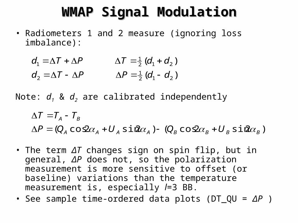
• Radiometers 1 and 2 measure (ignoring loss imbalance):
Note: d1 & d2 are calibrated independently
• The term ΔT changes sign on spin flip, but in general, ΔP does not, so the polarization measurement is more sensitive to offset (or baseline) variations than the temperature measurement is, especially l=3 BB.
• See sample time-ordered data plots (DT_QU = ΔP )
)2sin2cos()2sin2cos(
)(
)(
2121
2
2121
1
BBBBAAAA
BA
UQUQP
TTT
ddPPTd
ddTPTd
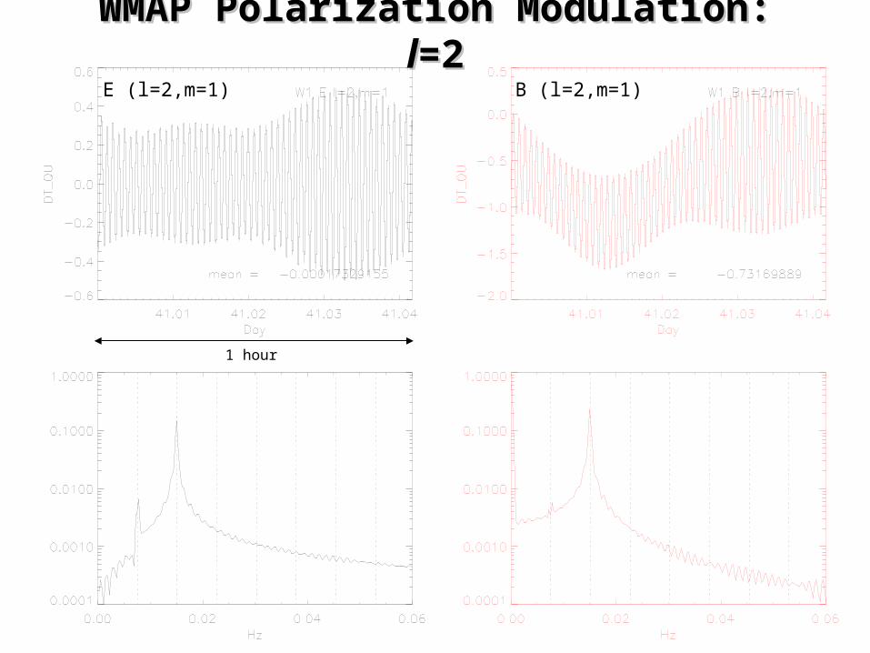
WMAP Polarization Modulation: WMAP Polarization Modulation: ll=2=2
1 hour
E (l=2,m=1) B (l=2,m=1)
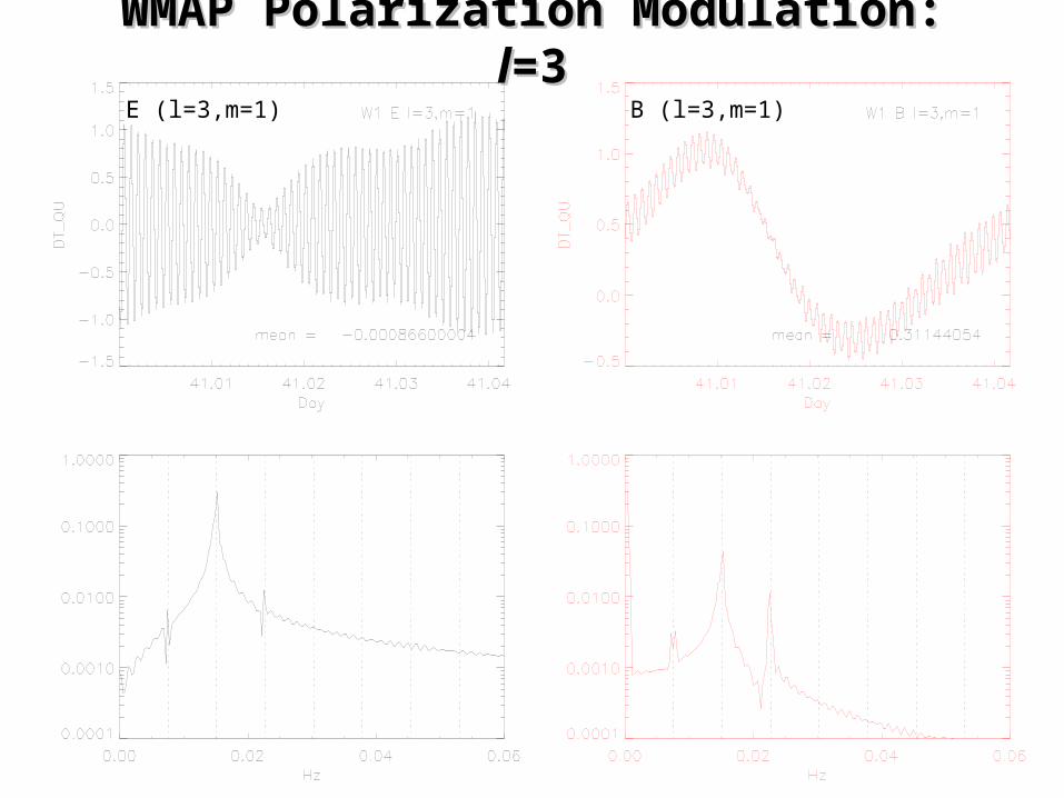
WMAP Polarization Modulation: WMAP Polarization Modulation: ll=3=3E (l=3,m=1) B (l=3,m=1)
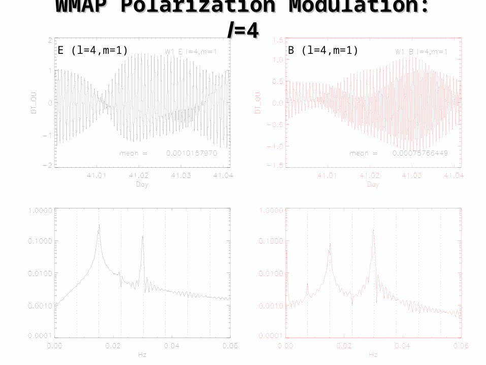
WMAP Polarization Modulation: WMAP Polarization Modulation: ll=4=4E (l=4,m=1) B (l=4,m=1)
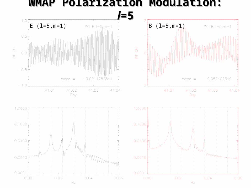
WMAP Polarization Modulation: WMAP Polarization Modulation: ll=5=5E (l=5,m=1) B (l=5,m=1)

WMAP Baseline ProcessingWMAP Baseline Processing• WMAP instrument baseline due to a combination of relatively fixed
instrument asymmetries (some with slow thermal dependence) and 1/f noise.
• On time scale longer than 1 hour, baseline parameters are fit and removed (see later). On time scales less than 1 hour, data are optimally filtered using a ~1/f noise model.
• The 1/f noise model must be accurately propagated from the time-ordered data to the sky map weight matrix:
• MUCH effort has been expended to carry this out for WMAP. We produce a pixel-pixel weight matrix at low resolution (HEALPix Nside = 16). We propagate this to power spectrum estimation using both pseudo-Cl and maximum likelihood methods.
• We test the error propagation by comparing the predicted errors to the scatter observed in the year-to-year data. In most cases the agreement is quite good (see next).
),()(),(),( 22211
1,
11
211
21
ptMttNptMMNMpptt
T
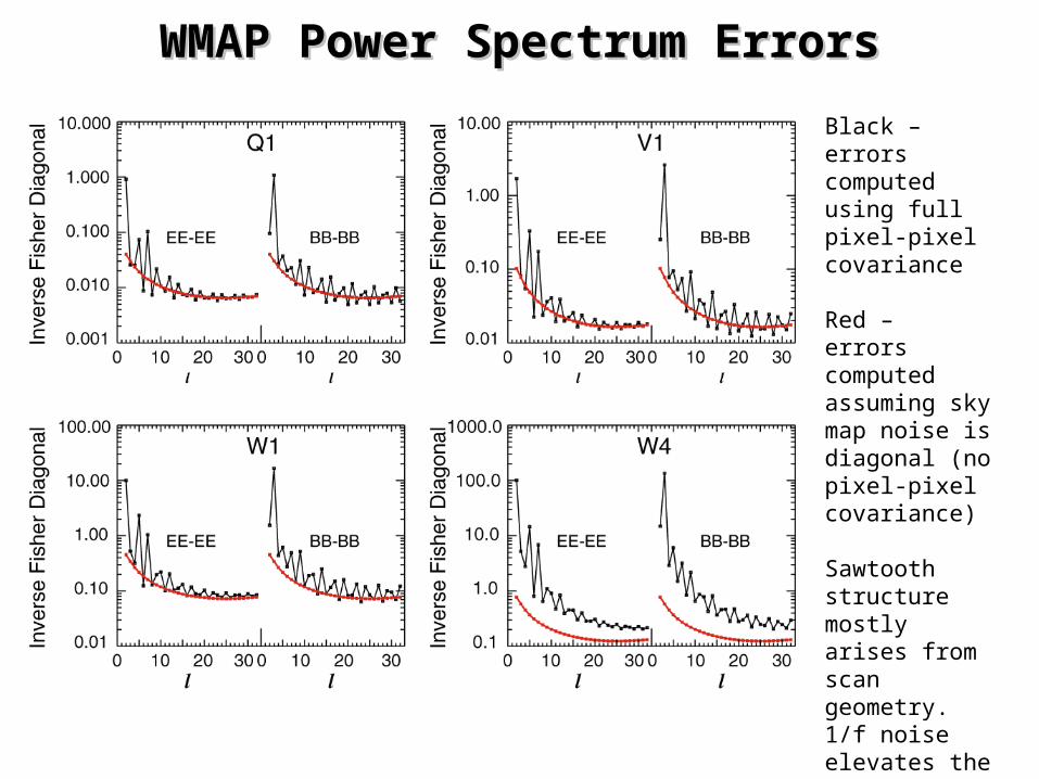
WMAP Power Spectrum ErrorsWMAP Power Spectrum Errors
Black –errors computed using full pixel-pixel covariance
Red –errors computed assuming sky map noise is diagonal (no pixel-pixel covariance)
Sawtooth structure mostly arises from scan geometry. 1/f noise elevates the overall level.
Page et al. ApJS,170, 335 (2007)
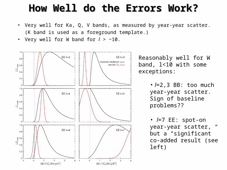
How Well do the Errors Work?How Well do the Errors Work?
• Very well for Ka, Q, V bands, as measured by year-year scatter.
(K band is used as a foreground template.)
• Very well for W band for l > ~10.
Reasonably well for W band, l<10 with some exceptions:
• l=2,3 BB: too much year-year scatter. Sign of baseline problems??
• l=7 EE: spot-on year-year scatter, but a “significant” co-added result (see left)
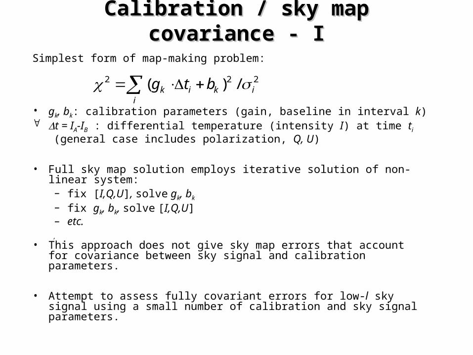
Calibration / sky map covariance - ICalibration / sky map covariance - I
Simplest form of map-making problem:
• gk, bk: calibration parameters (gain, baseline in interval k) t = IA-IB : differential temperature (intensity I) at time ti
(general case includes polarization, Q, U)
• Full sky map solution employs iterative solution of non-linear system: – fix [I,Q,U], solve gk, bk
– fix gk, bk, solve [I,Q,U]– etc.,
• This approach does not give sky map errors that account for covariance between sky signal and calibration parameters.
• Attempt to assess fully covariant errors for low-l sky signal using a small number of calibration and sky signal parameters.
222 /)( ikii
k btg
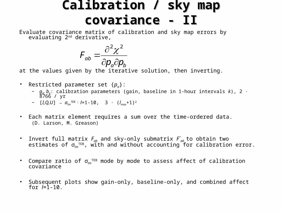
Calibration / sky map covariance - IICalibration / sky map covariance - II
Evaluate covariance matrix of calibration and sky map errors by evaluating 2nd derivative,
at the values given by the iterative solution, then inverting.
• Restricted parameter set {pa}:– gk, bk: calibration parameters (gain, baseline in 1-hour intervals k), 2 · 8766 / yr– [I,Q,U] → alm
TEB ; l=1-10, 3 · (lmax+1)2
• Each matrix element requires a sum over the time-ordered data. (D. Larson, M. Greason)
• Invert full matrix Fab and sky-only submatrix F´ab to obtain two estimates of σlmTEB,
with and without accounting for calibration error.
• Compare ratio of σlmTEB mode by mode to assess affect of calibration covariance
• Subsequent plots show gain-only, baseline-only, and combined affect for l=1-10.
baab ppF
22
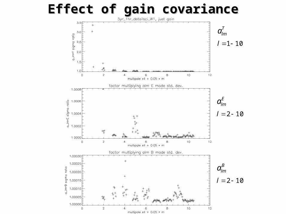
Effect of gain covarianceEffect of gain covariance
101 l
Tlma
102 l
Elma
102 l
Blma
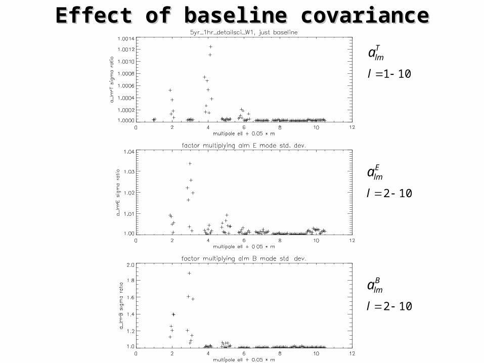
Effect of baseline covarianceEffect of baseline covariance
101 l
Tlma
102 l
Elma
102 l
Blma
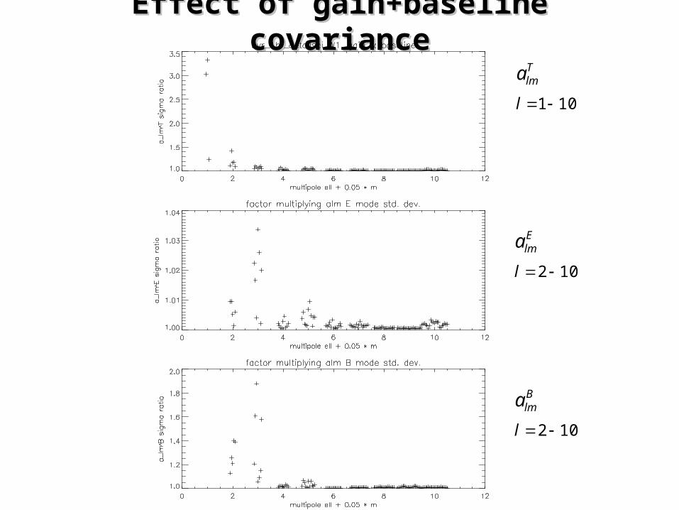
Effect of gain+baseline covarianceEffect of gain+baseline covariance
101 l
Tlma
102 l
Elma
102 l
Blma
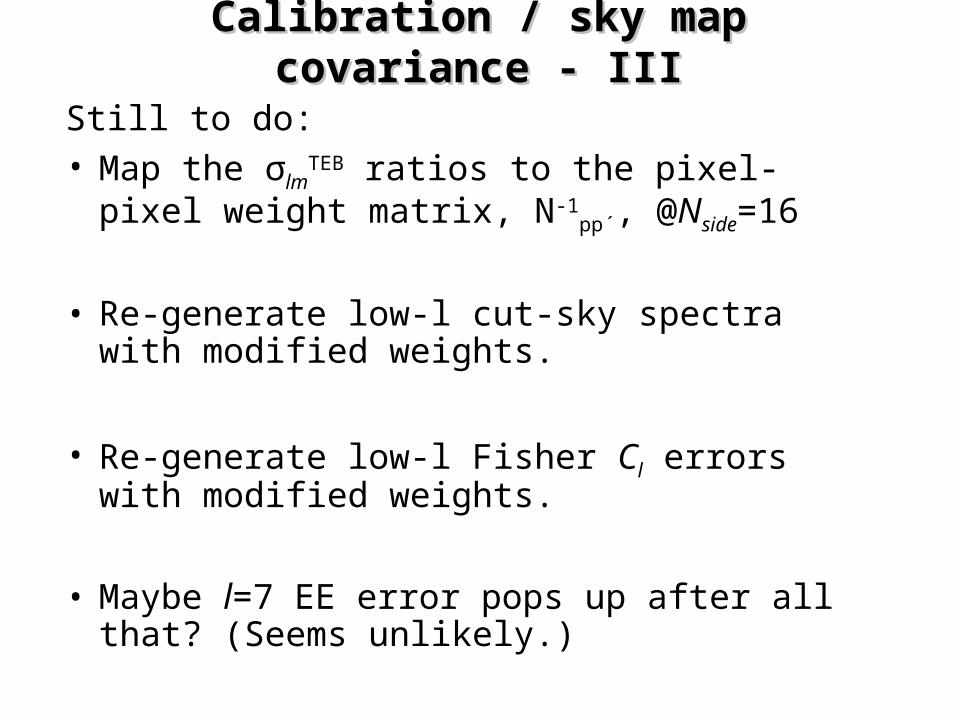
Calibration / sky map covariance - IIICalibration / sky map covariance - III
Still to do:• Map the σlm
TEB ratios to the pixel-pixel weight matrix, N-1
pp´, @Nside=16
• Re-generate low-l cut-sky spectra with modified weights.
• Re-generate low-l Fisher Cl errors with modified weights.
• Maybe l=7 EE error pops up after all that? (Seems unlikely.)
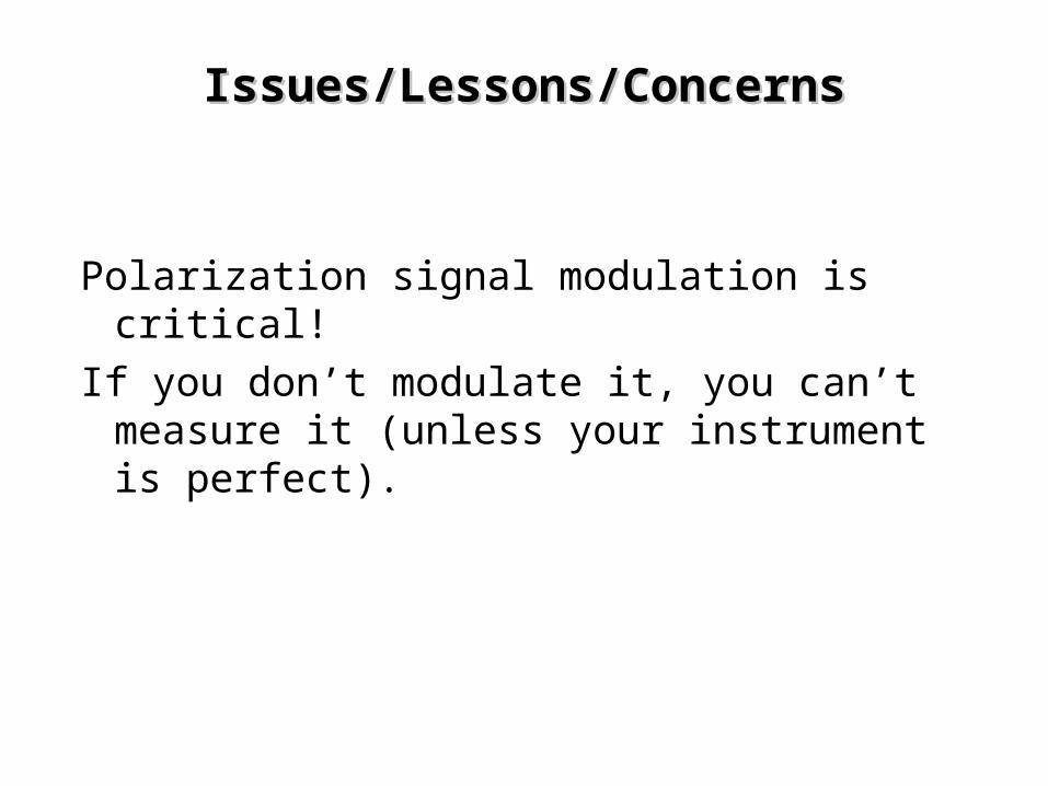
Issues/Lessons/ConcernsIssues/Lessons/Concerns
Polarization signal modulation is critical!
If you don’t modulate it, you can’t measure it (unless your instrument is perfect).

The End
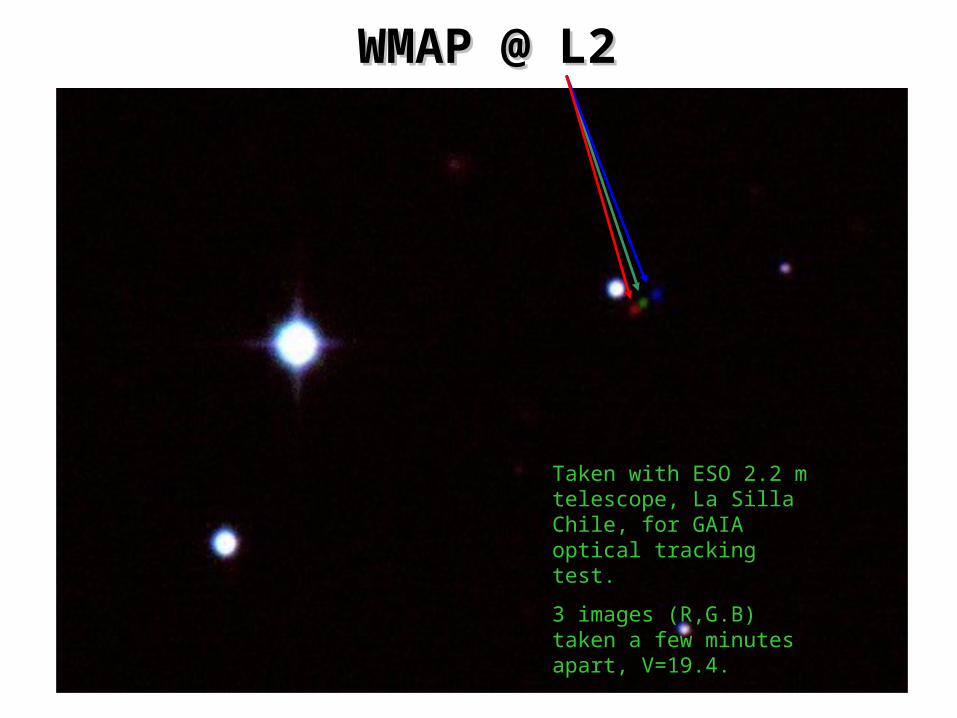
Taken with ESO 2.2 m telescope, La Silla Chile, for GAIA optical tracking test.
3 images (R,G.B) taken a few minutes apart, V=19.4.
WMAP @ L2WMAP @ L2
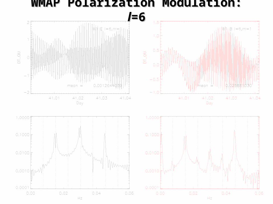
WMAP Polarization Modulation: WMAP Polarization Modulation: ll=6=6
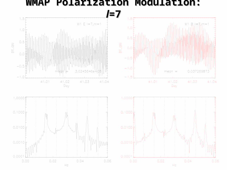
WMAP Polarization Modulation: WMAP Polarization Modulation: ll=7=7
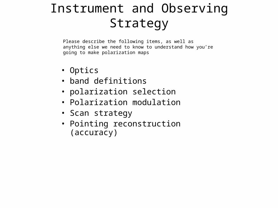
Instrument and Observing Strategy
• Optics • band definitions • polarization selection • Polarization modulation• Scan strategy• Pointing reconstruction (accuracy)
Please describe the following items, as well as anything else we need to know to understand how you’re going to make polarization maps