wmd-05s motorized electromechanical wicket...
TRANSCRIPT

Electromechanical
Wicket Gate
WMD-05SAssembly And Operation Manual
Motorized
РОСС. RU. М . В0
ТУ -00 -8 -20
E 35 0691
3428 0 0504654 12
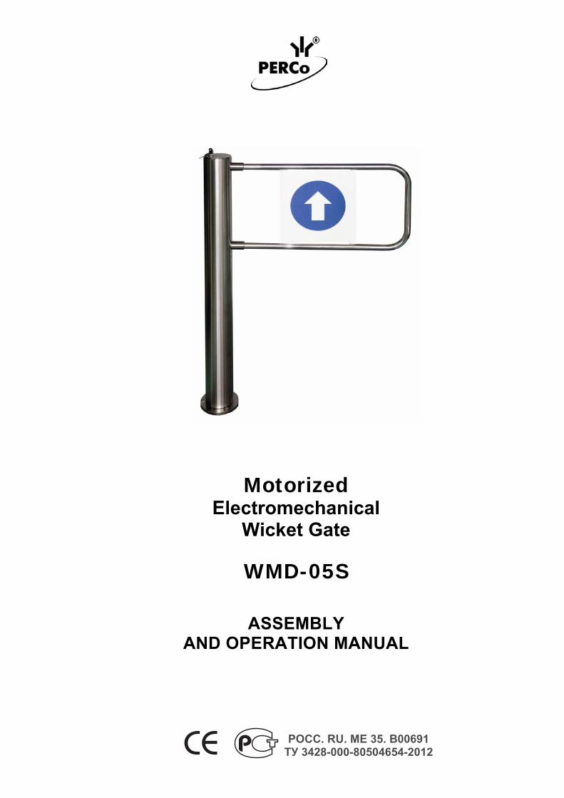
Motorized Electromechanical
Wicket Gate
WMD-05S
ASSEMBLY AND OPERATION MANUAL
РОСС. RU. МЕ 35. В00691 ТУ 3428-000-80504654-2012

CONTENTS
1. APPLICATION........................................................................................................4 2. OPERATION CONDITIONS....................................................................................4 3. TECHNICAL SPECIFICATIONS.............................................................................5 4. STANDARD DELIVERY SET .................................................................................6 5. OPTIONAL EQUIPMENT SUPPLIED ON REQUEST ............................................6 6. PRODUCT DESCRIPTION .....................................................................................7
6.1. Main features....................................................................................................7 6.2. Design ..............................................................................................................7 6.3. Control over the wicket gate ...........................................................................12
6.3.1. Operation from the remote control panel .............................................12 6.3.2. Operation from a wireless remote control ............................................12 6.3.3. Operation from ACS via an ACS connector.........................................12
6.4. Unblocking of the wicket gate with a mechanical release key........................14 7. SAFETY REQUIREMENTS ..................................................................................15
7.1. Installation safety............................................................................................15 7.2. Safety during operation ..................................................................................15
8. ASSEMBLY AND INSTALLATION.......................................................................15 8.1. General recommendations .............................................................................15 8.2. Assembly and installation sequence ..............................................................16
9. OPERATING THE WICKET GATE.......................................................................20 9.1. Power-up ........................................................................................................20 9.2. Operating modes when controlled from the RC panel and an ACS. ..............20 9.3. Operation from external power supply ...........................................................23 9.4. Operation from the built-in SPS......................................................................23
10. TROUBLESHOOTING........................................................................................24 11. MAINTENANCE..................................................................................................25 12. MARKING AND PACKAGING............................................................................25 13. TRANSPORTATION AND STORAGE................................................................25 APPENDIX A ............................................................................................................26 APPENDIX B ............................................................................................................28
Assembly and Operation Manual
4
Dear Customer! Thank you for purchasing the PERCo product. Please follow instructions given in this Manual carefully, and this quality product will provide many years of trouble-free use.
The Assembly and Operation Manual (hereinafter – the Manual) contains the instructions you will need for safe transportation, storage, installation, operation and maintenance of the WMD-05S electromechanical motorized wicket gate (hereinafter – the wicket gate).
The product installation must be carried out by qualified installers in strict accordance with the Manual.
Abbreviations adopted in the Manual: CU – control unit; SPS – standby power supply; ACS – access control system; RC panel – remote control panel.
1.1. APPLICATION APPLICATION
The wicket gate is designed for managing pedestrian flows at entrance points of industrial facilities, banks, administrative buildings, retail outlets, railway terminals, airports, etc.
To ensure fast and convenient passage it is recommended to install one wicket gate per every 500 entrants.
2.2. OPERATION CONDITIONS OPERATION CONDITIONS
The wicket gate with regard to resistance to environmental exposure complies with GOST 15150, category U 4 (operation in premises with climate control).
The control unit with regard to resistance to environmental exposure complies with GOST 15150, category NF 4 (operation in premises with climate control).
Operation of the wicket gate is allowed at ambient air temperature from +1 to +55°С and at relative air humidity of up to 70% at +27°С.
Operation of the control unit is allowed at ambient air temperature from +1 to +40°С and at relative air humidity of up to 60% at +20°С.
WMD-05S Electromechanical Motorized Wicket Gate
5
3.3. TECHNICAL SPECIFICATIONS TECHNICAL SPECIFICATIONS
AC operating voltage ....................................................................... 220±22 V AC/50 Hz Wicket gate operating voltage from an external power supply unit . 22-28 V DC Power consumption ......................................................................... max. 60 W Passage modes ............................................................................... 3 Throughput rate in the single passage mode................................... 12 persons/min. Minimum duration of operation / number of passages when powered by built-in SPS......................................................... 1,5 h/ 1 200 passages Overall dimensions:
– CU (L x W x H) ...................................................................... 295x290 x 75.5 mm – remote control panel ............................................................. 121x80x20 mm – wicket gate (L x W x H) ......................................................... 773×145×1012mm – wicket gate ............................................................................ 1023×145×1012mm – wicket gate ............................................................................ 1233×145×1012mm
Passageway width ........................................................................... 700 mm Passageway width ........................................................................... 950 mm Passageway width ........................................................................... 1150 mm Net weight, max:
– CU ......................................................................................... 9.6 kg – remote control panel ............................................................. 0.35 kg – wicket gate ............................................................................ 25.0 kg
Mean time to failure ......................................................................... min. 500,000 passages Mean lifetime.................................................................................... min. 8 years Electric shock protection class:
– CU ..................................................................I according to GOST R IEC 335-1-94 – gate post ........................................................III according to GOST R IEC 335-1-94
Ingress Protection Rating: Wicket gate post .............................................................................. IP41 under EN 60529 Control unit....................................................................................... IP40 under EN 60529
Important Note. The CU-05.2 power supply can be effected either from the AC mains 220V/50Hz or from an external DC power supply 24V via the CU “Bat=24V” connector. External power supply unit 24V DC is not included in the standard deliver set and is customer supply. Power supply unit specifications: 24V DC, minimum 2,5A.
With 650 mm swing panel With 900 mm swing panel With 1100 mm swing panel
Assembly and Operation Manual
6
4.4. STANDARD DELIVERY SET STANDARD DELIVERY SET
Gatepost ............................................................................................................................... 1 Swing panel with fasteners (650 mm) **** .............................................................................. 1 Swing panel with fasteners (900 mm) **** .............................................................................. 1 Swing panel with fasteners (1100 mm) **** ............................................................................ 1 Double-sided plastic info sign............................................................................................... 1 Control unit CU-05.2 with 1.5 m power cable....................................................................... 1 Remote control panel H-06/4 with cable 6.6 m long............................................................. 1 Control cable (4m)***** ........................................................................................................... 1 Power cable (4 m)***** ............................................................................................................ 1 Mechanical release key ........................................................................................................ 2 Assembly and Operation Manual ......................................................................................... 1 Certificate ............................................................................................................................. 1 Package: Box 1 (a wicket gate post and a control unit) ....................................................................... 1 Box 2 (a swing panel with a double-sided info sign) ............................................................ 1 Spare parts: Fuse:
1 A (5x20 mm) ............................................................................................................ 1 2 A (5x20 mm) ............................................................................................................ 1
ACS connector: DBH 15F cable socket ................................................................................................ 1 H9 connector case ...................................................................................................... 1
XLR3 cable socket for external power supply connection..................................................... 1 Installation tools: Screw 4x20............................................................................................................................ 3 Plastic dowel ......................................................................................................................... 3 Hex-nut wrench S5.......................................................................................................... 1
5.5. OPTIONAL EQUIPMENT SUPPLIED ON REQUEST OPTIONAL EQUIPMENT SUPPLIED ON REQUEST
Wireless remote control kit (consists of a receiver and 2 transmitters (tags) with operation range up to 40 m).................................................................................................................. 1 Siren (for alerts on unauthorized entry attempts) ................................................................. 1 Intrusion detector .................................................................................................................. 1
**** Size of the swing panel is chosen by a Client. ***** Maximum allowable cable length is 30 m
WMD-05S Electromechanical Motorized Wicket Gate
7
6.6. PRODUCT DESCRIPTION PRODUCT DESCRIPTION
6.1.6.1. Main features Main features
6.1.2. The wicket gate can be operated autonomously from the remote control panel or wireless remote control as well as from an access control system (ACS).
6.1.3. When operated from the ACS, there are two variants of the gate control – pulse control mode and potential control mode.
6.1.4. The wicket gate is a normally closed unit, i.e. when the power is off the wicket gate is “locked for entry and exit” – the swing panel is locked in home position.
6.1.5. Main features of the wicket gate: low power consumption – max 60W; safe operating voltage – max. 28 V DC; a built-in SPS to keep the wicket gate operative during a mains failure
(uninterrupted operation is minimum 1.5 hours or 1,200 passages). Inbuilt SPS consists of two 12 V batteries which automatically charge when the power supply is on. When the power is off the wicket gate automatically switches to operation from the batteries.
the wicket gate features electrical drive with an encoder, which allows for correct registration of opening of the wicket gate when operated in an ACS;
a mechanical release lock built in the gate post to unlock the wicket gate with a key and provide free rotation of the swing panel in emergency cases;
the wicket gate can be equipped with swing panels of 3 different sizes: 650, 900 or 1100 mm.
Control unit of the wicket gate features possibility of connecting emergency unblocking device to it;
All elements of the wicket gate apart from double-sided info sign are made of stainless steel.
6.2.6.2. Design Design
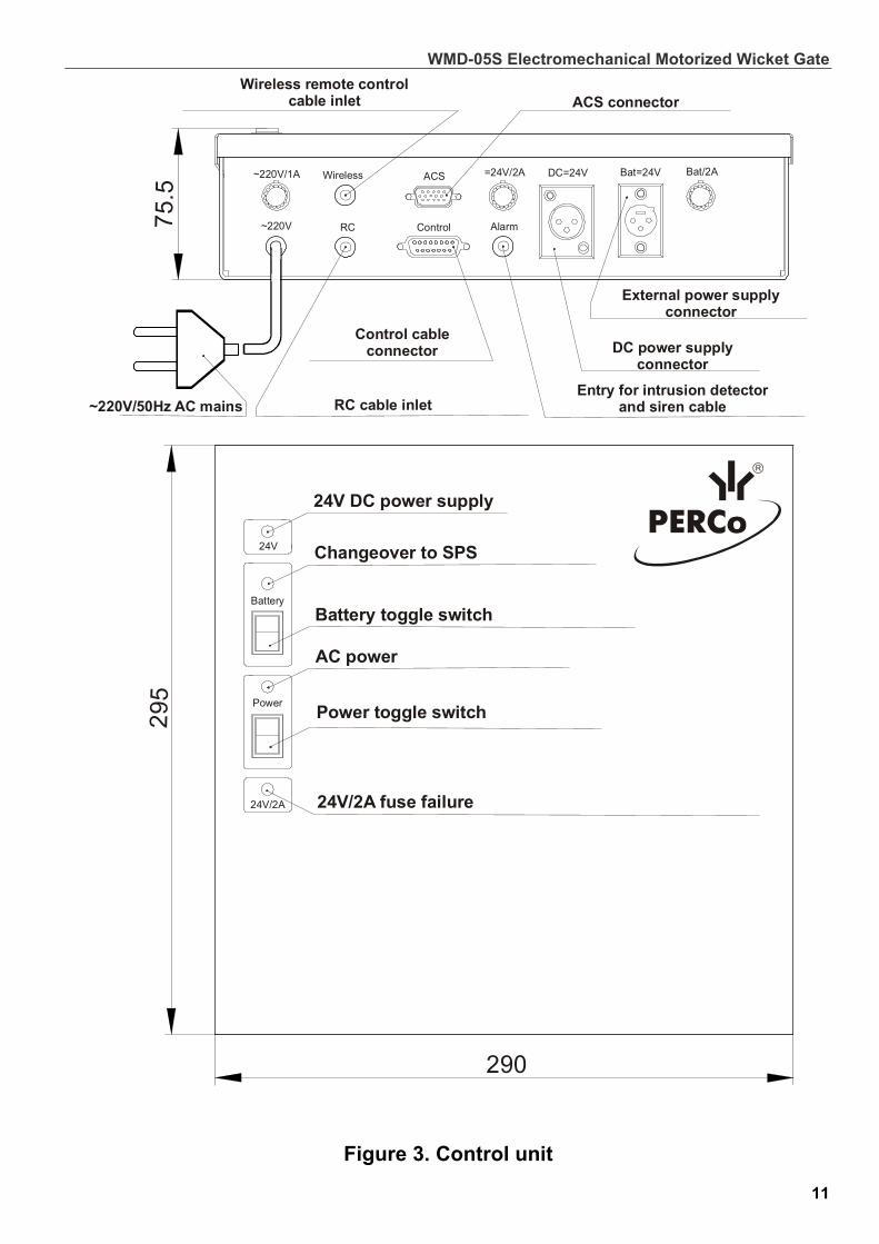
6.2.1. Design of the wicket gate is shown in Figure 1. The numbers of the items in brackets are given according to Figure 1 unless stated otherwise. 6.2.2. The WMD-05S consists of a rotary post (1), stationary post with flange (2), a swing panel (3) with an info sign (4). 6.2.3. The gate post is floor mounted, fixed with bolts M10x70 with recessed hexahedron. 6.2.4. In the gate post there are a rotor electric drive, an electromagnetic stopper unit, bearing units, a power module to control the electric drive and transmit signals from sensors and encoder, and a block of cable connectors (16). 6.2.5. On the rotary post cover (5) there is a mechanical release lock (6) intended for unlocking the wicket gate with a mechanical release key (7) in emergency cases. 6.2.6. The double-sided plastic info sign (4) is set into the swing panel (3) with fastenings (15). 6.2.7. The control unit (the CU) (8) is connected to the gate post with a DC power cable (11) and a control cable (10). The remote control panel (9) is connected to the CU with a cable (12). The CU (8) is responsible for the wicket gate powering and control. The CU (see Fig. 3) comes as a stand-alone device in a metal case with pull-resistant fasteners for wall- or desk-mounting.

Assembly and Operation Manual
6.2.8.
8
The remote control panel (9) serves for manual setting of the operating modes and indication thereof. It comes as a compact desktop device with a shockproof plastic case and a flexible multicore cable (12) to connect to the CU (8) via the cable input in the bottom part of the control unit (see Fig. 3 and Fig. 1A, Appendix A).
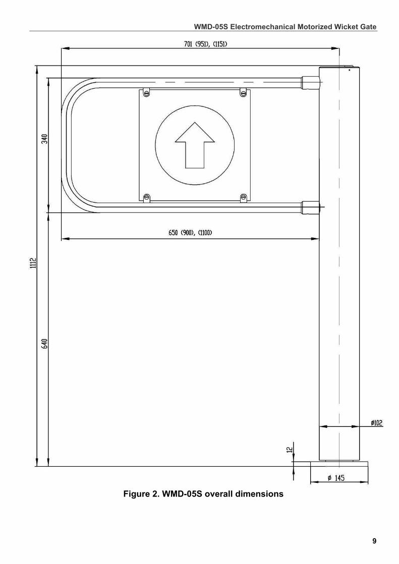
Figure 1. WMD-05S overall view
1 – rotary post; 2 – stationary post with flange; 3 – swing panel; 4 – double-sided plastic info sign; 5 – cover; 6 – mechanical release lock; 7 – mechanical release key; 8 – control unit; 9 – remote control panel; 10 – control cable; 11 – power cable; 12 – remote control
panel cable; 13 – AC mains cable; 14 – coupling fitting; 15 – fastening; 16 – cable connector block.
WMD-05S Electromechanical Motorized Wicket Gate
Figure 2. WMD-05S overall dimensions
9
Assembly and Operation Manual
10
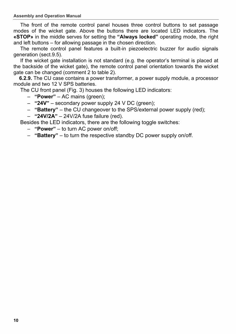
The front of the remote control panel houses three control buttons to set passage modes of the wicket gate. Above the buttons there are located LED indicators. The «STOP» in the middle serves for setting the “Always locked” operating mode, the right and left buttons – for allowing passage in the chosen direction.
The remote control panel features a built-in piezoelectric buzzer for audio signals generation (sect.9.5).
If the wicket gate installation is not standard (e.g. the operator’s terminal is placed at the backside of the wicket gate), the remote control panel orientation towards the wicket gate can be changed (comment 2 to table 2).
6.2.9. The CU case contains a power transformer, a power supply module, a processor module and two 12 V SPS batteries.
The CU front panel (Fig. 3) houses the following LED indicators: “Power” – AC mains (green); “24V” – secondary power supply 24 V DC (green); “Battery” – the CU changeover to the SPS/external power supply (red); “24V/2A” – 24V/2A fuse failure (red).
Besides the LED indicators, there are the following toggle switches: “Power” – to turn AC power on/off; “Battery” – to turn the respective standby DC power supply on/off.
WMD-05S Electromechanical Motorized Wicket Gate
Battery
Power
24V
24V/2A
295
75 .
5
290
ACSWireless
ControlRC Alarm
Bat=24VDC=24V
~220V
Battery toggle switch
Power toggle switch
24V/2A fuse failure
AC power
24V DC power supply
~220V/1A =24V/2A Bat/2A
External power supplyconnector
DC power supplyconnector
Entry for intrusion detectorand siren cable
Control cableconnector
RC cable inlet~220V/50Hz AC mains
Wireless remote controlcable inlet ACS connector
Changeover to SPS
Figure 3. Control unit
11
Assembly and Operation Manual
12
The CU case houses the following: - AC power cable input “220V”; - cable connector for wireless remote control “Wireless”; - cable entry for remote control panel “RC”; - ACS connector “ACS”; - control cable connector “Control”; - cable connector for intrusion detector, siren and emergency unblocking device
“Alarm”; - gate power supply connector “DC=24V”; - external power supply connector “Bat = 24V”; - fuse holder with “220V/1A” fuse; - “Bat/2A” fuse holder*; - fuse holder with “=24V/2A” fuse.
* WARNING! To prevent accidental power-up of the CU when in transit, the "Bat/2A" fuse is not installed and it is provided together with the set of spare parts.
Contact locations for an intrusion detector and a siren are given in Fig. 1А (Appendix A).
6.3.6.3. Control over the wicket gate Control over the wicket gate
The wicket gate can be operated from: - the remote control panel; - a wireless remote control; - an access control system.
66..33..11.. OOppeerraattiioonn ffrroomm tthhee rreemmoottee ccoonnttrrooll ppaanneell
The following operating modes can be set from the remote control panel (ref. Table 2): always locked; always free; single passage in chosen direction. For a “Single passage in chosen direction” mode it is possible to change passage
waiting time by installing jumpers on the processor module (Fig. 1 Appendix A1).
6.3.2.6.3.2. Operation from a wireless remote control Operation from a wireless remote control
Operation of the wicket gate from a wireless remote control is similar to that from the wired remote control. Assembly and operation Manual for the MSRF-04 wireless remote control is supplied with a delivery set of the wireless remote control.
Please refer to Figure 2A of the Appendix A for connection layout.
6.3.3.6.3.3. Operation from ACS via an ACS connector Operation from ACS via an ACS connector
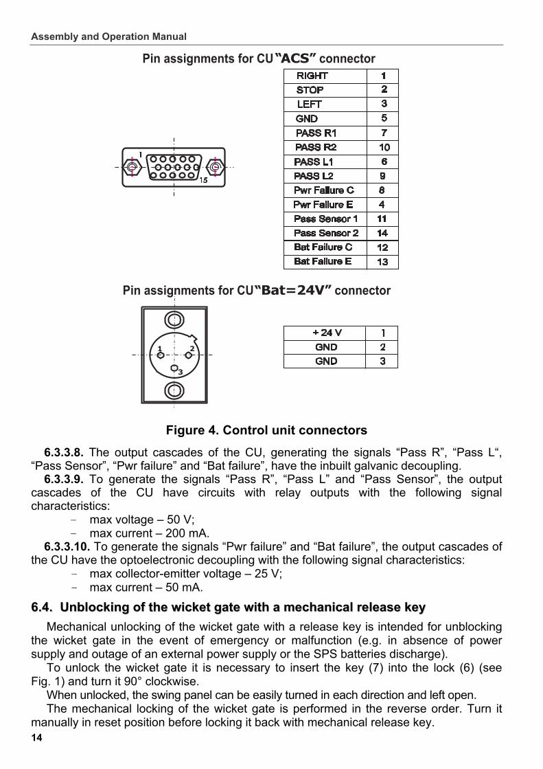
6.3.3.1. An ACS controller is cabled to the “ACS” connector of the CU (Fig. 3). The ACS connector is included in the set of spare parts of standard delivery set.
6.3.3.2. “ACS” connector contacts assignment is given in Figure 4. 6.3.3.3. Control over the wicket gate can be carried out in either pulse or potential
control mode. Pulse control mode: the wicket gate is operated by input of a low-level signal, or by
closing of the contacts “RIGHT”, “LEFT”, “STOP” with the “GND” contact of the “ACS” connector. The minimum control signal duration should be 100 ms.
WMD-05S Electromechanical Motorized Wicket Gate
13
Potential control mode: the wicket gate is operated by input of a low-level signal or by closing of the contacts ”RIGHT”/”LEFT” and “GND”. The “STOP” contact of the “ACS” connector is not used.
The set operating mode is cancelled by removal of the low-level signal or by breaking of the contacts “RIGHT”/”LEFT” and “GND” of the “ACS” connector.
6.3.3.4. Either control mode is set by a jumper on the X5 connector of the CU processor module (see Fig. 1A, Appendix A). The pulse control mode is preset at the factory.
6.3.3.5. The control element in the ACS can be a normally open relay contact or a circuit with open collector output and the following signal characteristics:
- voltage at the open contact – 5±0.5 V; - voltage at the closed contact (low-level) – max 0.8 V; - current via the closed contact – max 1.5 mA.
6.3.3.6. When the passage mode is set the swing panel (3) will turn in chosen direction. Speed and turn direction of the swing panel are controlled by signals of electrical driver encoder.
The “PASS R1(R2)” and “PASS L1(L2)” contacts of the CU “ACS” connector (see Fig. 4) are open in the reset state. At the swing panel turn, depending on the set passage direction, either the contacts “PASS R1” and “PASS R2” or the contacts “PASS L1” and “PASS L2” are closed. Duration of the generated signals depends on the time period the wicket gate stays open.
6.3.3.7. Additionally, the ACS is provided with the following signals: – “Pwr failure” – AC mains failure. Collector (+) (Pwr failure C) and emitter (-)
(Pwr failure E) of a transistor of galvanic decoupling circuit. At AC mains failure high level signal is generated (transistor is closed);
– “Bat failure” – the SPS or external power supply failure. Collector (+) (Bat failure C) and emitter (-) (Bat failure E) of a transistor of galvanic decoupling circuit. At the SPS failure (voltage falls to 22.5 V), a high-level signal is generated (closed transistor).
– “Pass Sensor” – status of intrusion detector. The data is transmitted to the ACS directly from the detector (if installed). Relay output (contacts Pass Sensor 1 and Pass Sensor 2).
Assembly and Operation Manual
14
Figure 4. Control unit connectors
6.3.3.8. The output cascades of the CU, generating the signals “Pass R”, “Pass L“, “Pass Sensor”, “Pwr failure” and “Bat failure”, have the inbuilt galvanic decoupling.
6.3.3.9. To generate the signals “Pass R”, “Pass L” and “Pass Sensor”, the output cascades of the CU have circuits with relay outputs with the following signal characteristics:
- max voltage – 50 V; - max current – 200 mA.
6.3.3.10. To generate the signals “Pwr failure” and “Bat failure”, the output cascades of the CU have the optoelectronic decoupling with the following signal characteristics:
- max collector-emitter voltage – 25 V; - max current – 50 mA.
6.4.. Unblocking of the wicket gate with a mechanical release key 6.4 Unblocking of the wicket gate with a mechanical release key
Mechanical unlocking of the wicket gate with a release key is intended for unblocking the wicket gate in the event of emergency or malfunction (e.g. in absence of power supply and outage of an external power supply or the SPS batteries discharge).
To unlock the wicket gate it is necessary to insert the key (7) into the lock (6) (see Fig. 1) and turn it 90° clockwise.
When unlocked, the swing panel can be easily turned in each direction and left open. The mechanical locking of the wicket gate is performed in the reverse order. Turn it
manually in reset position before locking it back with mechanical release key.

WMD-05S Electromechanical Motorized Wicket Gate
15
7.7. SAFETY REQUIREMENTS SAFETY REQUIREMENTS
7.1.7.1. Installation safety Installation safety
Installation should be performed by qualified personnel only, in strict accordance with the Manual and general electrical safety requirements for electrical and installation work.
Only serviceable tools should be used. All the connections should be performed only after the CU is disconnected from the
power supply. Cables should be laid in accordance with electrical safety requirements.
7.2.7.2. Safety during operation Safety during operation
7.2.1. Observe general safety requirements for use of electrical equipment. 7.2.2. The wicket gate is designed to use 220±22 V AC / 50Hz mains. Use a voltage
stabilizer to prevent possible malfunction in the event of a voltage surge. 7.2.3. DON’TS:
– Do not install the CU on electrically conductive floors and in damp areas, or use it in environments different from those given in sect. 2 of the Manual.
– Do not take the cover off the CU or change the fuses unless the CU is disconnected from the power supply.
– Do not let bulky objects with overall dimensions exceeding the passageway width be carried through the passageway area.
– Do not let the swing panel or the gate post be subjected to jerks and jolts that can cause mechanical deformation.
– Do not use abrasive or chemically active substances to clean surfaces.
8.8. ASSEMBLY AND INSTALLATION ASSEMBLY AND INSTALLATION
8.1.8.1. General recommendations General recommendations
8.1.1. Proper installation is critical to performance and serviceability of the wicket gate. We advise you to study this Manual before installation work and follow the instructions to the latter.
8.1.2. We recommend: to mount the wicket gate on flat, solid concrete floors (grade 400 or higher), stone
or similar foundations at least 150 mm thick; to make sure the mounting foundation is horizontal and flat, so that all the mount
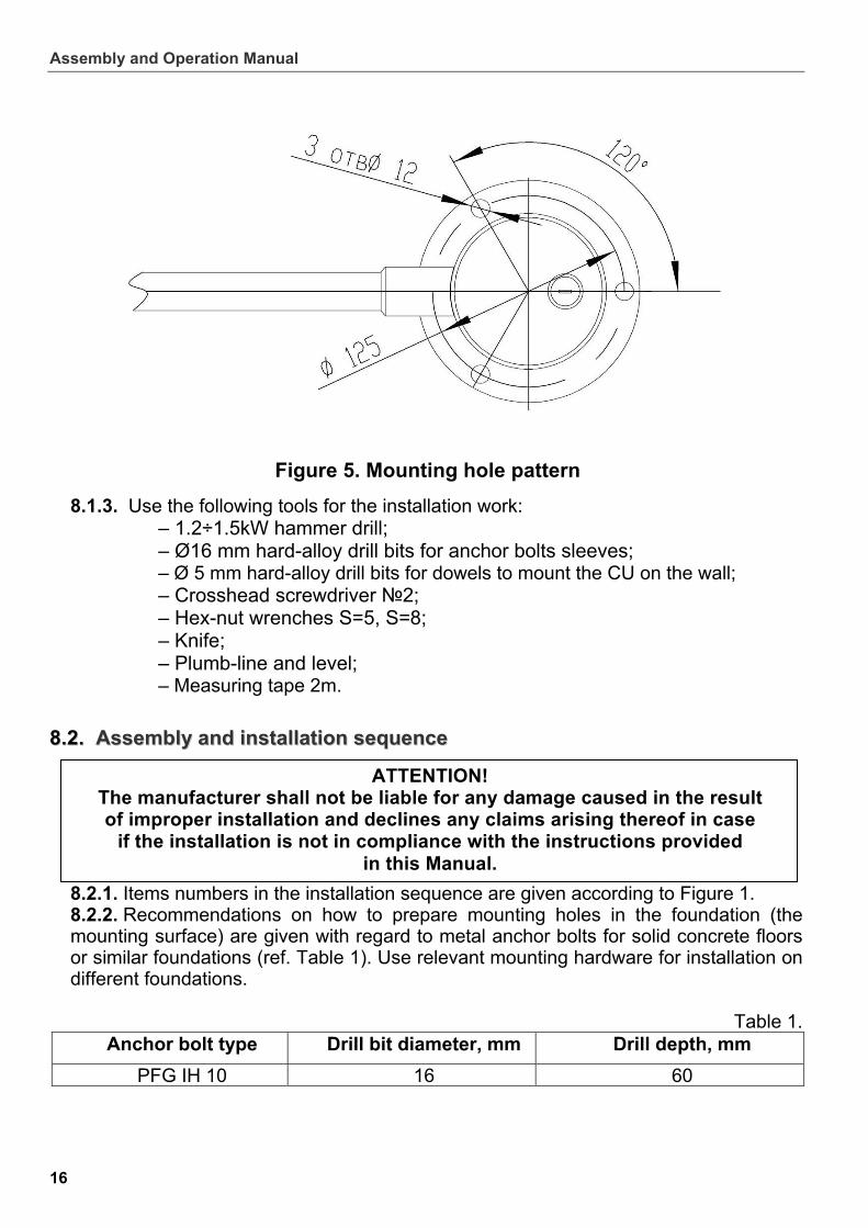
points lie in the same plane; to employ reinforcing elements 450х450х200 mm for softer grounds; to mark the mounting holes according to the enclosed mounting hole pattern (see
Fig. 5); to control the vertical position of the gate post during installation.
Assembly and Operation Manual
16
Figure 5. Mounting hole pattern
8.1.3. Use the following tools for the installation work: – 1.2÷1.5kW hammer drill; – Ø16 mm hard-alloy drill bits for anchor bolts sleeves; – Ø 5 mm hard-alloy drill bits for dowels to mount the CU on the wall; – Crosshead screwdriver №2; – Hex-nut wrenches S=5, S=8; – Knife; – Plumb-line and level; – Measuring tape 2m.
8.2.8.2. Assembly and installation sequence Assembly and installation sequence
8.2.1. Items numbers in the installation sequence are given according to Figure 1.
ATTENTION! The manufacturer shall not be liable for any damage caused in the result of improper installation and declines any claims arising thereof in case
if the installation is not in compliance with the instructions provided in this Manual.
8.2.2. Recommendations on how to prepare mounting holes in the foundation (the mounting surface) are given with regard to metal anchor bolts for solid concrete floors or similar foundations (ref. Table 1). Use relevant mounting hardware for installation on different foundations.
Table 1. Anchor bolt type Drill bit diameter, mm Drill depth, mm
PFG IH 10 16 60
WMD-05S Electromechanical Motorized Wicket Gate
17
8.2.3. Assembly and installation of the wicket gate
– Unpack the box with equipment, check carefully the delivery set (sect. 4); – mark the mounting holes as per Figure 5 and electric raceways for the control cable
(10) and the power cable (11); – prepare electric raceways and mounting holes for PFG IH 10 anchor bolts to fix the
wicket gate; – put the anchor bolts sleeves into the mounting holes; – lay out the control cable (10) and the power cable (11) from the control unit to the
gate post (1); – take the cable connector block (16), mounted on the spring pins, out of the stationary
post with flange (2); – connect the control cable and the power cable to the cable connector block (16); – install the cable connector block (16) into the stationary post with flange (2) at height
suitable for further installation; – install the gate post (2) upright into the run position (it is recommended to use joint
liners if need be); CAUTION! The gate post is heavy, hold it to prevent the fall! – fix the gate post flange with three screws M10x70 in accordance with Figure 1; – take the swing panel (3) out of the transportation box; – mount the swing panel into the coupling fittings (14) of the rotary post (1); – tighten the mounting screws through the coupling fittings’ holes with the S=5 hex-nut
wrench; – check the swing panel (3) to be properly fixed; – set the double-sided plastic info sign (4) into the swing panel (3) and fix it with the
fastenings (15). The wicket gate is assembled. 8.2.4. Check free rotation of the swing panel. To do so unlock the wicket gate with the
mechanical release key (7) (sect. 6.4) The swing panel should be able to turn by hand easily in either direction. Lock the
wicket gate with the key after the check. 8.2.5. Installation of the CU: Installation of the control unit (8) should be carried out considering that the convenient
access to the “Power” toggle switch is provided (Fig. 3). The CU (8) should be mounted on the wall upright with the connectors down. The AC power cable should easily reach the mains plug.
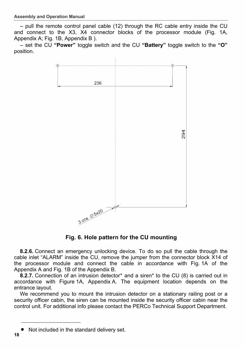
– mark out the holes for wall mounting of the control unit (8) as shown in Figure 6; – drill the holes and insert the plastic dowels included in the delivery set; – mount the CU (8) using two screws and fix it with the bottom screw to prevent
accidental pulling off. – connect the cable (10) to the CU “Control” connector (Fig. 3); – connect the power cable (11) to the CU “DC=24V” connector (Fig. 3);
Assembly and Operation Manual
18
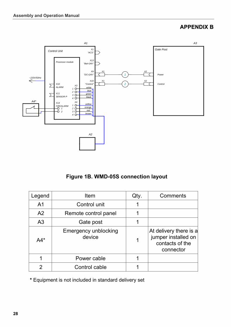
– pull the remote control panel cable (12) through the RC cable entry inside the CU and connect to the X3, X4 connector blocks of the processor module (Fig. 1A, Appendix A; Fig. 1B, Appendix B ).
– set the CU “Power” toggle switch and the CU “Battery” toggle switch to the “O” position.
Fig. 6. Hole pattern for the CU mounting
8.2.6. Connect an emergency unlocking device. To do so pull the cable through the cable inlet “ALARM” inside the CU, remove the jumper from the connector block X14 of the processor module and connect the cable in accordance with Fig. 1A of the Appendix A and Fig. 1B of the Appendix B.
8.2.7. Connection of an intrusion detector* and a siren* to the CU (8) is carried out in accordance with Figure 1A, Appendix A. The equipment location depends on the entrance layout.
We recommend you to mount the intrusion detector on a stationary railing post or a security officer cabin, the siren can be mounted inside the security officer cabin near the control unit. For additional info please contact the PERCo Technical Support Department.
Not included in the standard delivery set.
WMD-05S Electromechanical Motorized Wicket Gate
19
Set the required operating modes of the wicket gate by installing or removing jumpers on the processor module in accordance figure 1A of Appendix A: – X5 (Pulse / potential control) jumper installed – pulse mode is selected, jumper removed – a potential control mode; – X6 (passage waiting time) with a jumper installed the passage waiting time will be 5 seconds, with jumper removed – swing panel will remain open until it receives stop signal from the remote control panel or from the ACS; – X13, for 650 mm swing panel, the jumper is installed, for swing panels 900 (1100) mm the jumper should be removed. The jumper is installed at delivery. All jumpers are installed at delivery.
After the installation is complete, check carefully by visual inspection all cables, all connections are correct and undamaged, and prepare for the wicket gate for first power up, freeing the passage.
Assembly and Operation Manual
20
9.9. OPERATING THE WICKET GATE OPERATING THE WICKET GATE
9.1.9.1. Power-up Power-up
Always observe general electric safety requirements when operating the wicket gate.
Make sure the power cable is intact, all the connections are correct and safe. 9.1.1. Prior to the wicket gate power-up, make sure the CU “Power" toggle switch and
the CU «Battery» toggle switch are in the “O” position. 9.1.2. Put the “Bat/2A” fuse included in the set of spare parts into its place. 9.1.3. Plug the CU power cable (13) into a 220 V / 50 Hz AC outlet.
DDOO NNOOTT ccoonnnneecctt tthhee CCUU ttoo tthhee mmaaiinnss wwiitthh cchhaarraacctteerriissttiiccss tthhaatt ddiiffffeerr ffrroomm tthhoossee ggiivveenn iinn tthhee sseeccttiioonn 33 ooff tthhiiss MMaannuuaall..
9.1.4. Set the CU «Power» toggle switch and the CU «Battery» toggle switch to the “I” position.
At the same time the indicators «Power» and «24V» on the CU will light up. All indicators on the RC panel (9) will light up and a two-tone signal will sound. Three seconds later only STOP indicator on the RC panel will stay lit, red. If the swing panel of the wicket gate was not in a reset state, the wicket gate will search
for the reset state and will switch to “Always locked” mode.
9.2.9.2. Operating modes when controlled from the RC panel and an ACS. Operating modes when controlled from the RC panel and an ACS.
After power-up the reset state of the wicket gate is Always locked mode (when the mechanical release lock is locked).
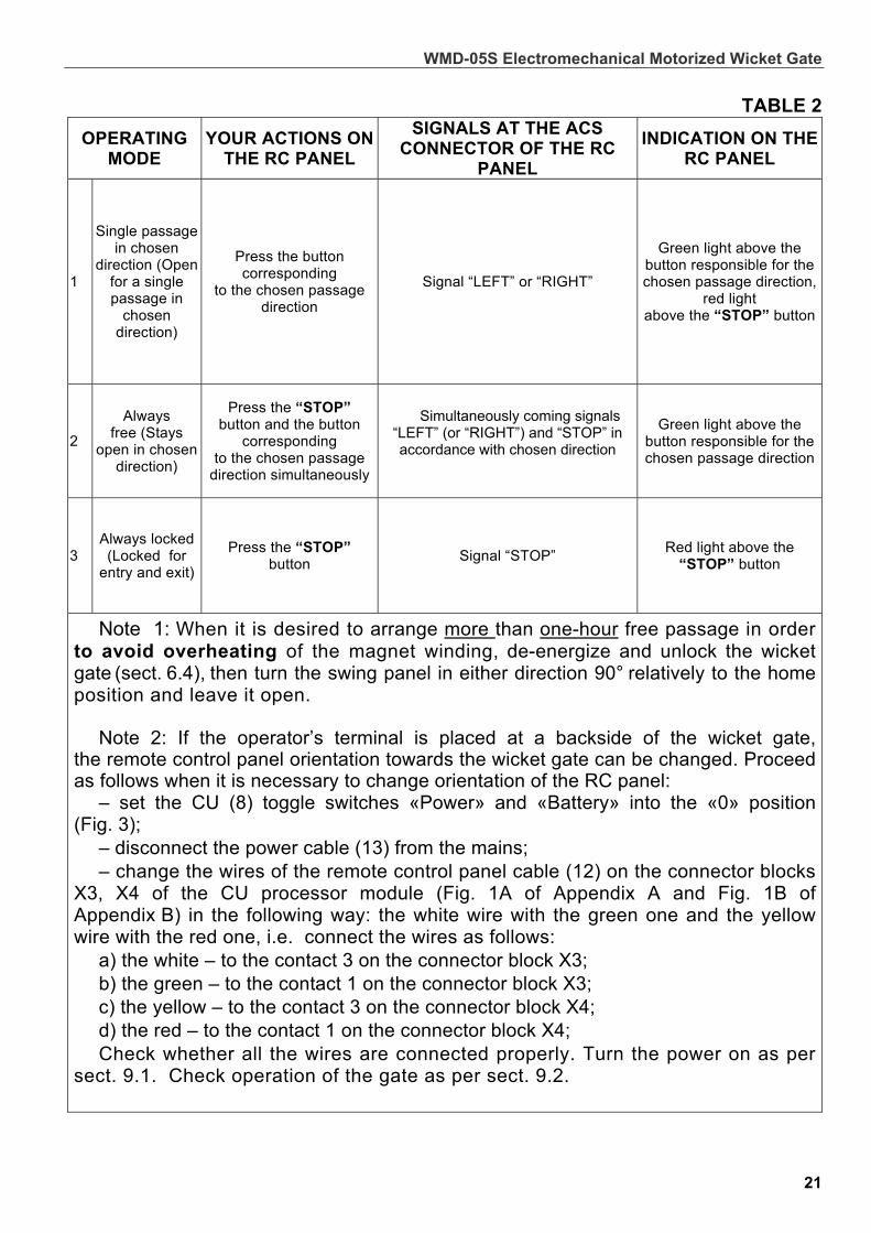
At a pulse control, setting of the operating modes of the wicket gates from the RC panel and their indication are as per Table 2.
WMD-05S Electromechanical Motorized Wicket Gate
21
TABLE 2
OPERATING MODE
YOUR ACTIONS ON THE RC PANEL
SIGNALS AT THE ACS CONNECTOR OF THE RC
PANEL
INDICATION ON THE RC PANEL
1
Single passage in chosen
direction (Open for a single passage in
chosen direction)
Press the button corresponding
to the chosen passage direction
Signal “LEFT” or “RIGHT”
Green light above the button responsible for the chosen passage direction,
red light above the “STOP” button
2
Always free (Stays
open in chosen direction)
Press the “STOP” button and the button
corresponding to the chosen passage
direction simultaneously
Simultaneously coming signals “LEFT” (or “RIGHT”) and “STOP” in accordance with chosen direction
Green light above the button responsible for the chosen passage direction
3 Always locked (Locked for
entry and exit)
Press the “STOP” button
Signal “STOP” Red light above the
“STOP” button
Note 1: When it is desired to arrange more than one-hour free passage in order to avoid overheating of the magnet winding, de-energize and unlock the wicket gate (sect. 6.4), then turn the swing panel in either direction 90° relatively to the home position and leave it open.
Note 2: If the operator’s terminal is placed at a backside of the wicket gate,
the remote control panel orientation towards the wicket gate can be changed. Proceed as follows when it is necessary to change orientation of the RC panel:
– set the CU (8) toggle switches «Power» and «Battery» into the «0» position (Fig. 3);
– disconnect the power cable (13) from the mains; – change the wires of the remote control panel cable (12) on the connector blocks
X3, X4 of the CU processor module (Fig. 1А of Appendix А and Fig. 1B of Appendix B) in the following way: the white wire with the green one and the yellow wire with the red one, i.e. connect the wires as follows:
а) the white – to the contact 3 on the connector block Х3; b) the green – to the contact 1 on the connector block Х3; c) the yellow – to the contact 3 on the connector block Х4; d) the red – to the contact 1 on the connector block Х4; Check whether all the wires are connected properly. Turn the power on as per
sect. 9.1. Check operation of the gate as per sect. 9.2.
Assembly and Operation Manual
22
AAnnyy ooppeerraattiinngg mmooddee iiss sseett bbyy pprreessssiinngg bbuuttttoonnss oonn tthhee RRCC ppaanneell ((oorr wwiirreelleessss rreemmoottee ccoonnttrrooll ttaagg)) iinn rreessppeeccttiivvee ccoommbbiinnaattiioonn::
– When the “STOP” button is pressed, the wicket gate switches into the “Always locked” operating mode, automatically returning the swing panel to the reset state.
– At setting of the “Single passage in chosen direction” mode the locking device unblocks and the electrical drive rotates the swing panel (3) in the direction of the permitted passage;
– the wicket gate remains open within passage waiting time (the factory-set passage waiting time is 5 sec, please refer to Appendix A for instructions on how to change it);
– with a waiting passage time set as infinite the wicket gate will remain open until STOP button on the RC panel is pressed or “STOP” signal is received on the ACS connector contact.
– After the passage waiting time elapses electrical drive brings the wicket gate into a reset state and the wicket gate switches to “Always locked” mode.
– The passage waiting time is counted after the swing panel rotates more than 83°. – In an “Always free” mode passage waiting time is not counted; the wicket gate
remains open for infinite time and switches to the “Always locked” mode after the STOP button is pressed (on the RC panel or wireless remote control tag) or till the “STOP” signal comes to the ACS connector contact;
– At entry of signals at “RIGHT”, “STOP”, “LEFT” contacts of the ACS connector the wicket gates is controlled in accordance with table 2;
– at simultaneous use of RC panel and signals of the ACS connector the last received command is executed.
When a new operating mode is set while the swing panel has not yet returned to the reset state:
– if the new passage direction is the same as the one set before, the wicket gate starts carrying out the operating mode immediately, without resetting the swing panel;
– if the new passage direction is opposite to the one set before, the operating mode is recorded into the memory buffer register of the CU and the wicket gate starts carrying out the operating mode only after the swing panel has returned to the reset state;
– if the "Always free" mode is set while the wicket gate is still in the "Single passage" mode, the wicket gate switches into the "Always free" mode but the swing panel holds the same open position, irrespective of the direction chosen for the "Always free" mode.
At potential control mode operating modes are set by holding signals “RIGHT” or “LEFT” on the ACS connector in accordance with the chosen passage direction.
It should be considered: – When a signal is sent, the gate opens and remains open for the duration of the
presence of the signal. – When the STOP button on the RC panel is pressed and held the gate will lock,
even if the “LEFT” (“RIGHT”) signal is present on the “ACS” connector. – When the “LEFT” (“RIGHT”) signal is removed from the “ACS” connector the gate
will lock. – The “STOP” Contact of the “ACS” connector is not used. – At pressing and keeping a direction button on the RC panel pressed the gate will
open in the corresponding direction and will remain open until you release the button on the RC panel.
WMD-05S Electromechanical Motorized Wicket Gate
23
– At opening the contacts at the X14 connector block (FIREALARM) of the processor module board by the control device generating emergency unblocking signal, regardless of the set passage mode, or ban of passage, the swing panel unblocks and the voltage from the wicket gate drive is removed, the wicket gate can be rotated manually in any direction.
– At closing contacts of the X14 connector block (FIREALARM) the wicket gate acts as at power-up and switches to “Always locked mode”.
To prevent failure of the electromechanical parts of the gate, in case of continuous
overheating due to forcing the wicket gate against rotating for more than 10 seconds, overload mode turns on. At the same time all three indicators of the RC panel will start blinking and the RC panel will generate a series of 3 short audio signals every 20 seconds. To exit overload mode manually return the wicket gate to its reset state.
9.3.9.3. Operation from external power supply Operation from external power supply
9.3.1. An external power supply is connected via the CU “Bat=24V” connector (see Fig. 3). Pin assignments of the “Bat=24V” connector are shown in Fig. 4.
9.3.2. The cable socket connector for external power supply is included in the set of spare parts.
9.3.3. To connect the external power supply: - set the CU toggle switches “Power” and “Battery” to the “O” position; - remove the “Bat/2A” fuse from its fuse holder on the CU panel; - connect the external power supply to the “Bat=24V” connector; - set the “Battery” toggle switch to the “I” position.
9.3.4. Operation from the external power supply is similar to operation from the built-in SPS as given in Clause 9.4 of the Manual.
9.4.9.4. Operation from the built-in SPS Operation from the built-in SPS
9.4.1. In case of AC mains failure the wicket gate remains in operation, the CU automatically switches to the built-in SPS (the CU “Battery” toggle switch is due to be in the “I” position).
9.4.2. When operating from the SPS, the CU “Power” light indicator goes out, the “Battery” light indicator on the CU is on.
The “Pwr failure” signal, notifying of the AC mains failure, is transmitted to the CU “ACS” connector. In about 5 seconds an intermittent light indication at 1 sec intervals is generated on the remote control panel.
9.4.3. At the SPS battery discharge down to 22±0.5 V, the “Bat failure” signal is transmitted to the CU “ACS” connector. An intermittent audio signal with 30 seconds interval (six short audio signals per every 30 sec), warning about the discharge, is generated from the remote control panel.
9.4.4. At the SPS battery discharge down to 20±5V, the wicket gate switches to the malfunction mode, the CU will automatically switch off.
9.4.5. When the AC mains is restored, the wicket gate returns to normal operation if the “Power” toggle switch is in the “I” position.
9.4.6. The built-in SPS battery will recharge automatically if the «Battery» toggle switch is in the “I” position.
Assembly and Operation Manual
CAUTION! The CU SPS contains the lead-acid batteries, which are not recommended
to be stored for a long time without recharge. For recharge during the storage period the CU should be switched
on for 24 hours every 8 months or every 2 months when stored at temperatures above +30 °C.
There is no need to connect the wicket gate or the remote control panel to the CU during recharge. Sequence of actions is given in Clause 9.4.
Operation time with the built-in SPS is 1.5 hours or 1,200 passages provided that the battery is fully charged.
24
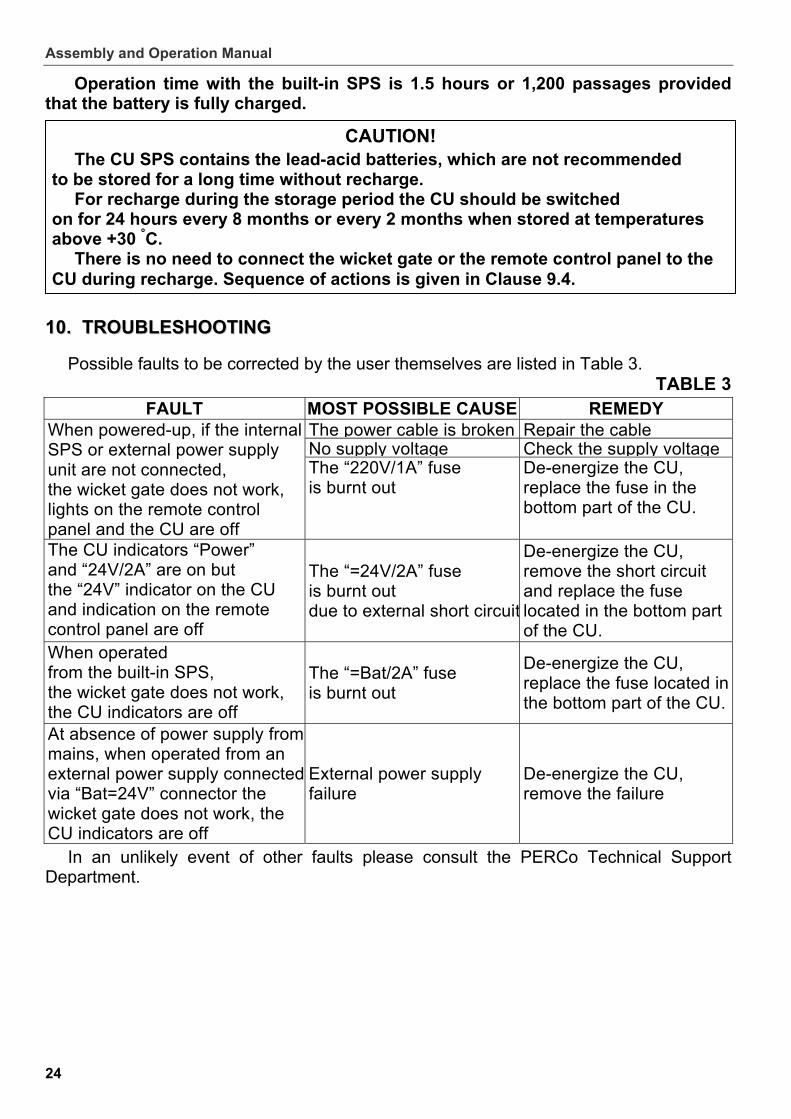
10.10. TROUBLESHOOTING TROUBLESHOOTING
Possible faults to be corrected by the user themselves are listed in Table 3. TABLE 3
FAULT MOST POSSIBLE CAUSE REMEDY The power cable is broken Repair the cable No supply voltage Check the supply voltage
When powered-up, if the internal SPS or external power supply unit are not connected, the wicket gate does not work, lights on the remote control panel and the CU are off
The “220V/1А” fuse is burnt out
De-energize the CU, replace the fuse in the bottom part of the CU.
The CU indicators “Power” and “24V/2A” are on but the “24V” indicator on the CU and indication on the remote control panel are off
The “=24V/2А” fuse is burnt out due to external short circuit
De-energize the CU, remove the short circuit and replace the fuse located in the bottom part of the CU.
When operated from the built-in SPS, the wicket gate does not work, the CU indicators are off
The “=Bat/2А” fuse is burnt out
De-energize the CU, replace the fuse located in the bottom part of the CU.
At absence of power supply from mains, when operated from an external power supply connectedvia “Bat=24V” connector the wicket gate does not work, the CU indicators are off
External power supply failure
De-energize the CU, remove the failure
In an unlikely event of other faults please consult the PERCo Technical Support Department.
WMD-05S Electromechanical Motorized Wicket Gate
25
11.11. MAINTENANCE MAINTENANCE
Technical maintenance of the wicket gate should be performed only by the manufacturer. We recommend using liquid non-abrasive cleansers containing ammonia to clean a wicket gate post and a swing panel when dirty.
12.12. MARKING AND PACKAGING MARKING AND PACKAGING
12.3 The wicket gate has the marking on the CU (8) and under the cover (5) of the rotary post (1). The marking contains the product name, the manufacture date, the serial number, the technical characteristics, the warranty term. To get access to the marking located under the cover (5) of the rotary post (1) unscrew 3 screws in the upper part of the wicket gate post using S1,5 wrench and lift the cover (5) of the rotary post. The marking on the CU (8) is located on its backside.
12.4 The wicket gate as standard (Ref. section 4) is packed in two transportation boxes. Box one contains a wicket gate post and a control unit, box two has swing panel with double-sided info sign packed in it.
13.13. TRANSPORTATION AND STORAGE TRANSPORTATION AND STORAGE
13.1 The wicket gate in the original package should be transported only in closed freight containers or other closed type cargo transport units.
13.2 The wicket gate should be stored in dry indoor facilities at ambient temperatures between –40°C and +45°C and at relative air humidity of up to 98% at +25°С.
13.3 After transportation or storage at below-zero temperatures or high air humidity, the wicket gate should be kept unpacked for minimum 24 hours under normal climate conditions (+18 °C, humidity – 60%) prior to installation.
13.4 During storage and transportation boxes with wicket gate posts can be stacked no more than 3 layers high, boxes with swing panels – no more than 10 layers high.
Assembly and Operation Manual
26
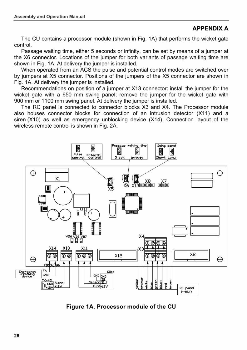
AAPPPPEENNDDIIXX AA
The CU contains a processor module (shown in Fig. 1A) that performs the wicket gate control.
Passage waiting time, either 5 seconds or infinity, can be set by means of a jumper at the X6 connector. Locations of the jumper for both variants of passage waiting time are shown in Fig. 1A. At delivery the jumper is installed.
When operated from an ACS the pulse and potential control modes are switched over by jumpers at X5 connector. Positions of the jumpers of the X5 connector are shown in Fig. 1A. At delivery the jumper is installed.
Recommendations on position of a jumper at X13 connector: install the jumper for the wicket gate with a 650 mm swing panel; remove the jumper for the wicket gate with 900 mm or 1100 mm swing panel. At delivery the jumper is installed.
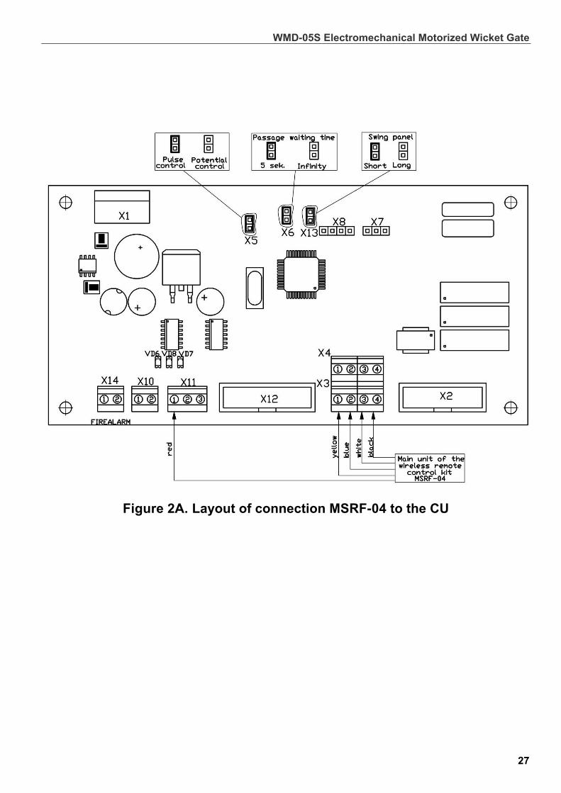
The RC panel is connected to connector blocks X3 and X4. The Processor module also houses connector blocks for connection of an intrusion detector (X11) and a siren (X10) as well as emergency unblocking device (X14). Connection layout of the wireless remote control is shown in Fig. 2A.
Figure 1A. Processor module of the CU
WMD-05S Electromechanical Motorized Wicket Gate
Figure 2A. Layout of connection MSRF-04 to the CU
27
Assembly and Operation Manual
28
AAPPPPEENNDDIIXX BB
1
4
2
3
X3
2 3
4
2
1
X4
A1
A2
1
brown
yellow
green
blue
X10
"DC=24V"
X9
X13
X1
X1
X2
X2
A4*
~220V/50Hz
X11
X14
X10
black
orange
"Control"
white
"Bat=24V"
X1
red
"ACS"
Processor module
Control Unit
Power
SENSOR P
FIREALARM
ALARM
1
2 Control
A3
Gate Post
Figure 1B. WMD-05S connection layout
Legend Item Qty. Comments
А1 Control unit 1
А2 Remote control panel 1
А3 Gate post 1
A4*
Emergency unblocking device
1
At delivery there is a jumper installed on
contacts of the connector
1 Power cable 1
2 Control cable 1
* Equipment is not included in standard delivery set


PERCo Industrial
Tel.: +7 812 321 61 72, +7 812 329 89 24
Fax: +7 812 292 36 08
Legal address: 123-V ul. Leona Pozemskogo,
Pskov, 180600, Russia
e-mail: [email protected]
www.percoweb.com

www.percoweb.com