woertz terminal block
DESCRIPTION
Woertz Terminal Block Industrial ElectronicsTRANSCRIPT

S C R E W T E R M I N A L S
Woertz AGHofackerstrasse 47, P.O. Box 948, CH-4132 Muttenz 1, SwitzerlandPhone ++41 (0)61 466 33 33, Fax ++41 (0)61 461 96 06www.woertz.ch
1 . 1
Woertz USA151 Discovery Drive, Unit 111Colmar, PA 18915Phone (215) 997 8855, Fax (800) 522-3868www.woertz-usa.com, e-mail: [email protected]

S t r u c t u r e o f t h e c a t a l o g
article description
approvals
general informationnominal cross-section
order number
suitable accessories
suitable mounting rail
ratings according to IEC
technical data
additionalinformation
mounting rails EN 60715 TH15
Woertz mounting rail
mounting rails EN 60715 TH35
ratings according to UL
catalog register 1section 1
page number
number of possiblelabels
insulating materialpolyamide 66
PA 666
1.1.3
Contents
I n t r o d u c t i o n p a g e s 11 . 1 . 4 tt o 11 . 1 . 1 4
S c r e w tt e r m i n a l s ff o r DD I N 3 5 rr a i l EE N 6 0 7 1 5 TT H 33 5
S e r i e s CC o m p a c t p a g e s 11 . 1 . 1 6 tt o 11 . 1 . 3 7
S e r i e s CC o m f o r t pp a g e s 11 . 1 . 3 8 tt o 11 . 1 . 5 6
B r a n c h i n g tt e r m i n a l s p a g e s 11 . 1 . 5 7 tt o 11 . 1 . 6 2
S p e c i a l ss e r i e s p a g e s 11 . 1 . 6 3 tt o 11 . 1 . 7 0
A c c e s s o r i e s p a g e s 11 . 1 . 7 1 tt o 11 . 1 . 1 0 7
S c r e w tt e r m i n a l s ff o r DD I N 1 5 rr a i l EE N 66 0 7 1 5 TT H 11 5
T e r m i n a l ss e r i e s p a g e s 11 . 1 . 1 0 8 tt o 11 . 1 . 1 1 5
A c c e s s o r i e s p a g e s 11 . 1 . 1 1 7 tt o 11 . 1 . 1 2 3
S c r e w tt e r m i n a l s ff o r WW o e r t z rr a i l 44 0 5 0 A
T e r m i n a l ss e r i e s p a g e s 11 . 1 . 1 2 4 tt o 11 . 1 . 1 3 2
A c c e s s o r i e s p a g e s 11 . 1 . 1 3 3 tt o 11 . 1 . 1 3 4
1
2
3
4
5
6
7
8
9
10
Company profileIntroduction
1.1.4
Hölstein branch
The Woertz company was founded in 1928; our head office is in Muttenz near Basle, Switzerland.
We are a family business with about 220 employees known as a quality manufacturer of circuitry accessories,
installation systems and electronic control systems.
Our goals are:
- security,
- user-friendliness,
- and easy handling of our products.
We are certified according to ISO 9001 and ISO 14001.
Our range of products includes:
- terminals, junction boxes, grounding products, surge protection devices, anchor channels and
anchoring studs
- flat cable installation systems
- floor ducts, double floor systems, under-window ducts
- electronic modules and interfaces.
The circuitry accessories and the electronic control systems are produced in our headquarters in Muttenz , the
duct and double floor systems in the branch located in Hölstein.
Hofackerstrasse 47, CH-4132 Muttenz,SwitzerlandTel. ++41 (0)61 / 466 33 33Fax ++41 (0)61 / 461 96 06
Bärenmattenstrasse 3, CH - 4434 Hölstein,Switzerland Tel. ++ 41 (0)61 / 956 56 56Fax ++ 41 (0)61 / 956 56 70
Muttenz head office

SQS certificateIntroduction
1.1.5
The SQS certificate ISO 9001 was issued to us 1987 for the first time and renewed regularly. ISO 14001 since 1996.
1

Properties of the insulating materialsIntroduction
1.1.6
The insulating body of our terminals is made of polyamide 66. Even if this polyamide is subjected to a constant temperature of 100°C, it fulfills the electri-cal, mechanical and chemical properties required in terminals. The typical features of polyamide 66 are hardness, rigidity, scuff resistance and thermal en-durance.
Fuse terminals and fuse plugs, where constant temperatures of over 100°C can occur, are made of polyamide 66 reinforced with fibreglass.Polyamide 66 is hardly combustible, self-extinguishing and halogen-free (when a fire breaks out, there can’t be any emanation of toxic gas combustion,which, alone or combined with humidity, could result in corrosive precipitations). Polyamide 66 (reinforced with fibreglass or non-reinforced) is approved by all leading certification and testing institutions.
General properties Density g/cm3
Humidity-absorption (normal conditions) %Water-absorption at 23°C (saturation) %
1.142.8 ± 0.38.5 ± 0.5
Mechanical properties Unit State of sample polyamide 66
Yield stress N/mm2drymoist
9065
Elongation at tear %drymoist
20> 50
Elastic modulus (tension test) N/mm2drymoist
34001700
Ductility (notch d=3mm) kJ/m2 dry 40
Indentation hardness N/mm2drymoist
170110
Thermal properties Unit State of sample polyamide 66Heat-resistance according to ISO 75
Process AProcess B
°C°C
drydry
105> 200
Fusion temperature °C / 260
Longitudinal expansion coefficient 1/K x 10-5 dry 7-10
Thermal conductivity W/(K x m) dry 0.23
Specific heat capacity J/(g x K) dry 1.7
Electrical properties Unit State of sample polyamide 66
Dielectric constant (105 Hz)drymoist
3.25.0
Dielectric loss factor tan δ (105 Hz)drymoist
0.0250.2
Dielectric strength kV/mmdrymoist
100-15030-80
Specific volume resistance Ω x cmdrymoist
1015
1012
Surface resistance ROA Ωdrymoist
1012
1010
Creep resistance CTI dry / moist > 600 (non-reinforced)
Burning behavior
according to VDE 0304, Teil 3 (5.70) class II baccording to FMVSS*-302(condition fulfilled: the flame goes out before the firstmarker is reached)
mm/min < 100* Federal Motor Vehicle Safety Standard No. 302, 1976 (sample 1 mm thick); see also DIN 75 200 (4.75)
according to UL Standard 94 (sample 1/16” thick) 94V-2
Toxic behavior halogen-free
Different types of connectionsIntroduction
1.1.7
1To connect one or more conductors with a clamping unit.Clamping unit of nickel-plated brass.Screws of stainless steel.Connecting bars of nickel-plated copper alloy.Corrosion resistant, also suitable for marine systems.Approved for hazardous locations.
Connecting terminalswith screw connections
without springs
wwiitthhoouutt aaddddiittiioonnaall sspprriinngg
To connect one or more conductors with a clamping unit.Clamping unit of nickel-plated brass.Screws and springs of stainless steel.Connecting bars of nickel-plated copper alloy.Corrosion resistant, also suitable for marine systems,for systems with high temperature variations, vibration resistant.Approved for hazardous locations.
wwiitthh aaddddiittiioonnaall sspprriinngg ttoo pprreevveenntt wwiirreess ffrroomm wwoorrkkiinngg lloooossee
To connect one main through conductor, stripped of its insulation at a stretch corresponding to the lengthof the terminal, and one or more stripped ends of branch conductors laid down on it. Always clamp mainconductor and branch conductor under all two or three clamping screws.U-shaped clamping body of nickel-plated brass.Pressure part, screws and sliding cover of nickel-plated brass.To insert the through conductor and one or more branch conductors pull off the sliding cover, unscrew clam-ping screws and remove pressure part. Insert main conductor and put branch conductor on it, so that theyare clamped by all two or three clamping screws. Very secure because the main conductor is not cut any-where.
Branching terminalswith screw connections for through conductors
without springs
CCllaammppiinngg ssccrreewwss wwiitthhoouutt sspprriinnggss
To connect one main through conductor, stripped of its insulation at a stretch corresponding to the lengthof the terminal, and one or more stripped ends of branch conductors laid down on it. Always clamp mainconductor and branch conductor under all two or three clamping screws.U-shaped clamping body of nickel-plated brass.Pressure part, sprung screws and sliding cover of nickel-plated brass. To insert the through conductor and one or more branch conductors pull off the sliding cover, unscrew clam-ping screws and remove pressure part. Insert main conductor and put branch conductor on it, so that theyare clamped by all two or three clamping screws. Very secure because the main conductor is not cutanywhere.For systems with high temperature variations, vibration resistant.Approved for hazardous locations.
SSpprruunngg ccllaammppiinngg ssccrreewwss
Connecting terminalswith screw connections
with springs
Branching terminalswith screw connectionsfor through conductors
with spring

Introduction
1.1.8
At least two unifilar conductors (solid conductors), multifilar conductors (rigid stranded conductors) or fine-ly stranded conductors (flexible conductors) of the terminal’s nominal cross-section can be connected to allterminals.
About thenominal cross-section of the screw terminals
Subdivision of the PEN conductor in a distribution systemEarthing
1.1.9
1
towards installation
3P+N+PE
3P+N+PE
2P+N+PE P+N+PE P+N+PE
PEPEN
Supply 3P+PENnon-throughFor feed lines
from overcurrent trips
NL1 L2 L3
N PE
If the cross-section of the neutral conductor is lower than or equal to6 mm2, the neutral conductor and the protective conductor must run sepa-rately.If the cross-section of the neutral conductor is higher than or equal to 10 mm2, the PEN conductor can be used.
When the PEN conductor is divided into a neutral and an earth conductor,a disconnecting unit must be inserted into the neutral conductor. Thisdisconnecting unit must fulfill the requirements of a neutral disconnectingterminal and be mounted correctly in the house wiring. It must always beeasy of access.
The presented neutral disconnecting terminals are perfect in accordancewith these requirements and when combined with detachable neutral con-nectors they give rise to the following applications.
The feed line of the distribution system is lead to terminals for 3 polar con-ductors and to the neutral connecting terminal fastened on the mountingrail of connecting terminals. The input of the neutral disconnecting termi-nal is then connected to a bare earthing terminal terminal on the moun-ting rail.
This is the way a PEN conductor can be subdivided within a distribution system with the help of a neutral disconnecting terminal and a bare earthingterminal.
The cover fitting this combination of terminals provides protection against any accidental contact as well as locking of the neutral disconnecting ter-minal.
If detachable neutral connectors and earthing terminals are mounted next to the outgoing terminals, any parallel connection of neutral and protec-tive conductors can be suppressed. The mounting rail provides the connection to the earth conductor, and the busbar of the detachable neutral con-nectors connected to the output of the neutral disconnecting terminal is joined to the neutral conductor.
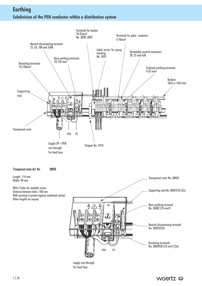
Subdivision of the PEN conductor within a distribution systemEarthing
1.1.10
PEPEN
Supply 3P+PENnon-throughFor feed lines
Terminals for busbar 10-35mm2
No. 3838, 3839
Bare earthing terminals 10-120 mm2
Label carrier for groupmarking No. 3459
Neutral disconnecting terminal 25, 63, 100 and 160A
Branching terminals 10-120mm2
Terminals for polar conductor4-70mm2
Detachable neutral connectors 20, 25 and 63A
Enclosed earthing terminals 4-35 mm2
Stopper No. 3418
Transparent cover
Supportingstud
Busbars10x2 or 10x3 mm
Transparent ccover AArt. NNo. 30050
Length: 114 mmWidth: 90 mm
With 2 holes for sealable screwsDistance between holes: 100 mmWith warning to protect against accidental contactOther lengths on request
Supply non-throughFor feed lines
Transparent cover No. 30050
Supporting stud No. 80059/55 (2x)
Bare earthing terminalNo. 30382 (10 mm2)
Neutral disconnecting terminal No. 30224/25A
Branching terminals No. 30842GR (10 mm2) (3x)
PEPEN
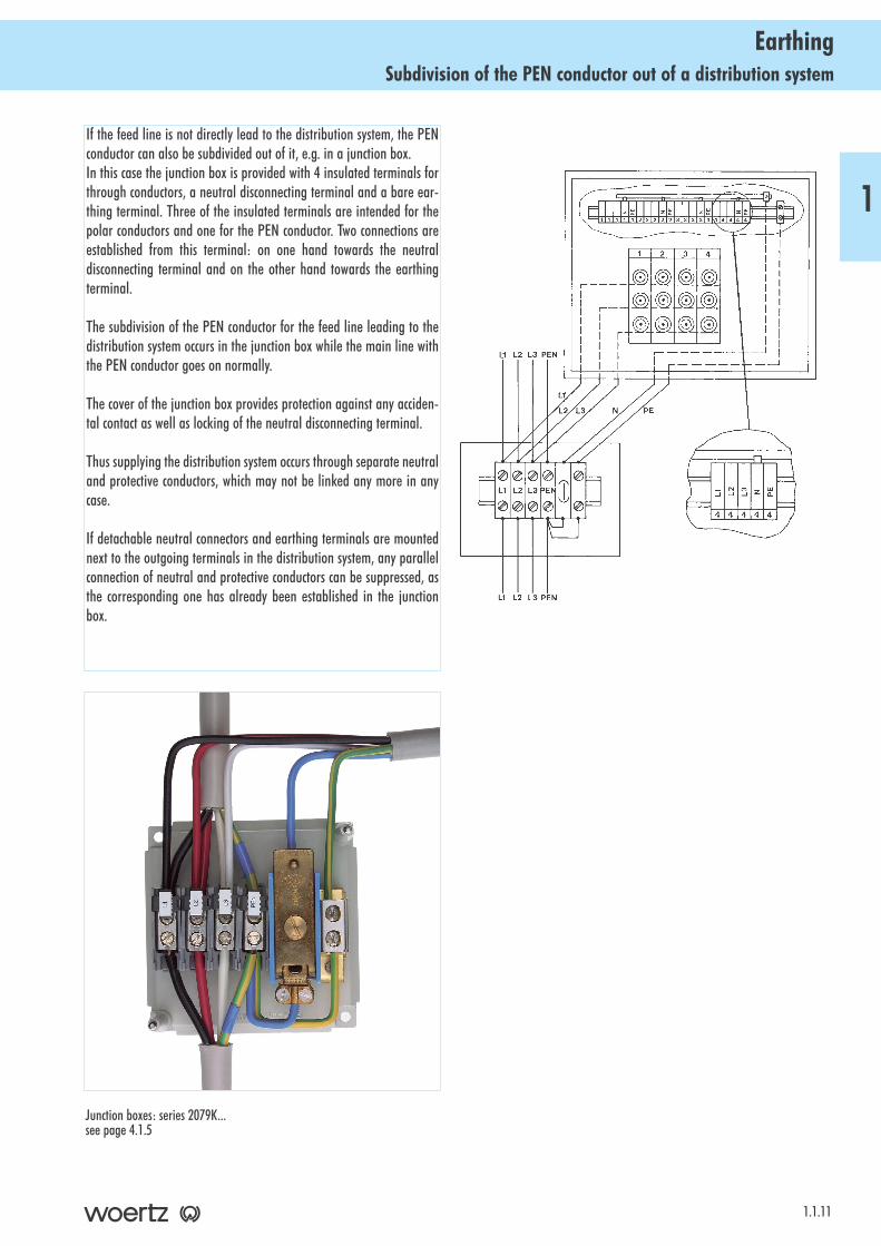
Subdivision of the PEN conductor out of a distribution systemEarthing
1.1.11
1
If the feed line is not directly lead to the distribution system, the PENconductor can also be subdivided out of it, e.g. in a junction box.In this case the junction box is provided with 4 insulated terminals forthrough conductors, a neutral disconnecting terminal and a bare ear-thing terminal. Three of the insulated terminals are intended for thepolar conductors and one for the PEN conductor. Two connections areestablished from this terminal: on one hand towards the neutraldisconnecting terminal and on the other hand towards the earthingterminal.
The subdivision of the PEN conductor for the feed line leading to thedistribution system occurs in the junction box while the main line withthe PEN conductor goes on normally.
The cover of the junction box provides protection against any acciden-tal contact as well as locking of the neutral disconnecting terminal.
Thus supplying the distribution system occurs through separate neutraland protective conductors, which may not be linked any more in anycase.
If detachable neutral connectors and earthing terminals are mountednext to the outgoing terminals in the distribution system, any parallelconnection of neutral and protective conductors can be suppressed, asthe corresponding one has already been established in the junctionbox.
Junction boxes: series 2079K...see page 4.1.5
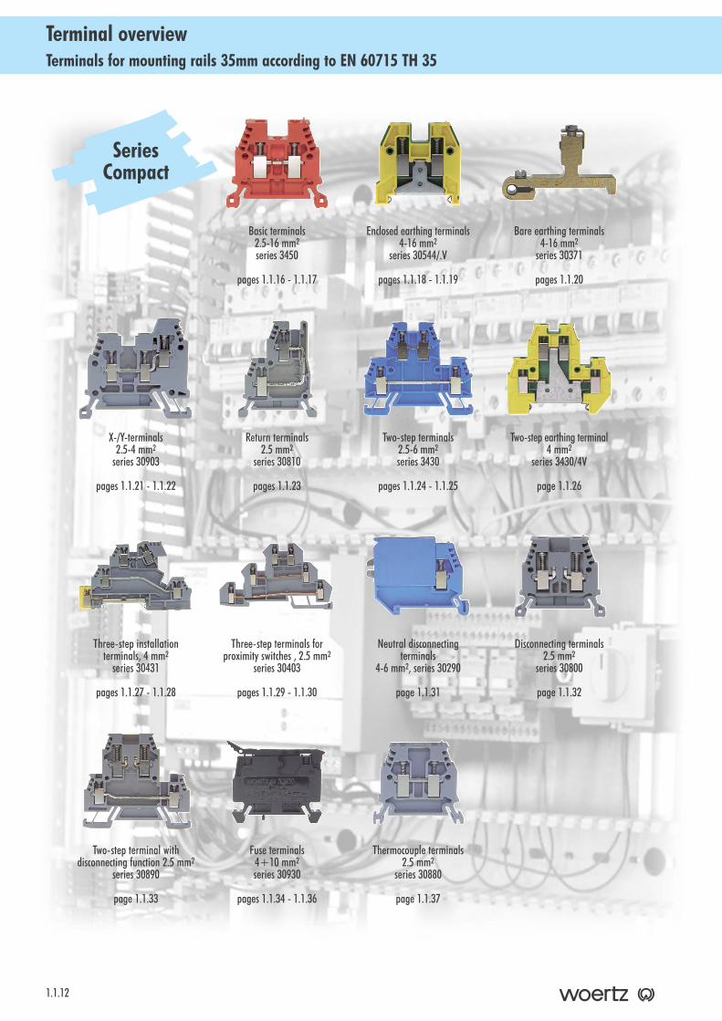
Terminals for mounting rails 35mm according to EN 60715 TH 35Terminal overview
1.1.12
Basic terminals 2.5-16 mm2
series 3450
pages 1.1.16 - 1.1.17
Enclosed earthing terminals4-16 mm2
series 30544/.V
pages 1.1.18 - 1.1.19
Bare earthing terminals 4-16 mm2
series 30371
pages 1.1.20
Return terminals2.5 mm2
series 30810
pages 1.1.23
X-/Y-terminals 2.5-4 mm2
series 30903
pages 1.1.21 - 1.1.22
Three-step installation terminals, 4 mm2
series 30431
pages 1.1.27 - 1.1.28
Two-step terminal withdisconnecting function 2.5 mm2
series 30890
page 1.1.33
Two-step terminals 2.5-6 mm2
series 3430
pages 1.1.24 - 1.1.25
Two-step earthing terminal4 mm2
series 3430/4V
page 1.1.26
Three-step terminals for proximity switches , 2.5 mm2
series 30403
pages 1.1.29 - 1.1.30
Neutral disconnectingterminals
4-6 mm2, series 30290
page 1.1.31
Disconnecting terminals 2.5 mm2
series 30800
page 1.1.32
Fuse terminals 4+10 mm2
series 30930
pages 1.1.34 - 1.1.36
Thermocouple terminals 2.5 mm2
series 30880
page 1.1.37
SeriesCompact
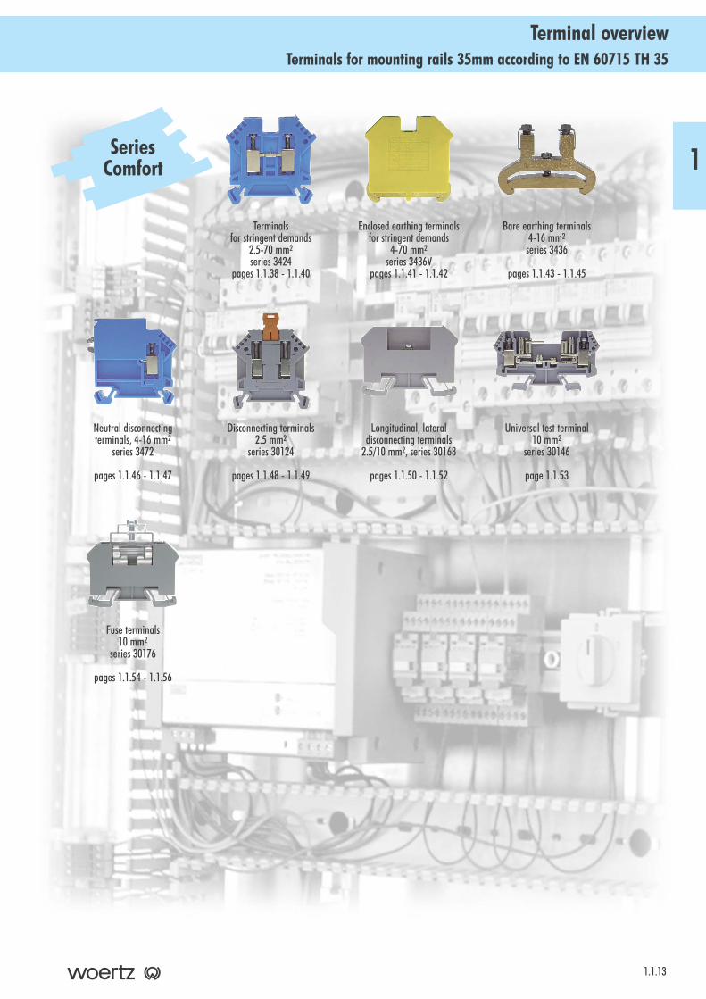
Terminals for mounting rails 35mm according to EN 60715 TH 35Terminal overview
1.1.13
Terminals for stringent demands
2.5-70 mm2
series 3424pages 1.1.38 - 1.1.40
Enclosed earthing terminalsfor stringent demands
4-70 mm2
series 3436Vpages 1.1.41 - 1.1.42
Bare earthing terminals 4-16 mm2
series 3436
pages 1.1.43 - 1.1.45
Disconnecting terminals 2.5 mm2
series 30124
pages 1.1.48 - 1.1.49
Neutral disconnectingterminals, 4-16 mm2
series 3472
pages 1.1.46 - 1.1.47
Fuse terminals 10 mm2
series 30176
pages 1.1.54 - 1.1.56
Longitudinal, lateraldisconnecting terminals
2.5/10 mm2, series 30168
pages 1.1.50 - 1.1.52
Universal test terminal 10 mm2
series 30146
page 1.1.53
SeriesComfort 1
Terminals for mounting rails 35mm according to EN 60715 TH 35Terminal overview
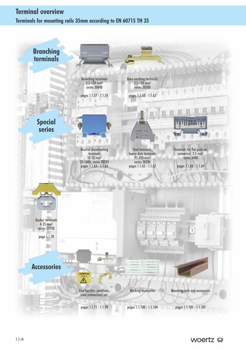
1.1.14
Branching terminals 2.5-120 mm2
series 30840
pages 1.1.57 - 1.1.59
Bare earthing terminals 2.5-120 mm2
series 30380
pages 1.1.60 - 1.1.62
Neutral disconnectingterminals
10-50 mm2
25-160A, series 30224pages 1.1.63 - 1.1.64
Stud terminals,heavy-duty terminals
95-240 mm2
series 30286pages 1.1.65 - 1.1.67
Terminals for flat push-onconnectors, 2.5 mm2
series 3440
pages 1.1.68 - 1.1.69
Busbar terminals4-35 mm2
series 30950
page 1.1.70
End barriers, partitions,cross-connections, etc.
pages 1.1.71 - 1.1.99
Mounting rails and accessories
pages 1.1.105 - 1.1.107
Marking accessories
pages 1.1.100 - 1.1.104
Branchingterminals
Specialseries
Accessories
1.1.15
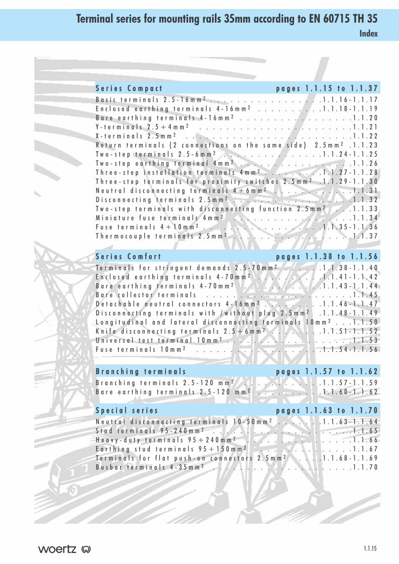
IndexTerminal series for mounting rails 35mm according to EN 60715 TH 35
S e r i e s CC o m p a c t p a g e s 11 . 1 . 1 5 tt o 11 . 1 . 3 7B a s i c t e r m i n a l s 2 . 5 - 1 6 m m 2 . . . . . . . . . . . . . . . . . 1 . 1 . 1 6 - 1 . 1 . 1 7E n c l o s e d e a r t h i n g t e r m i n a l s 4 - 1 6 m m 2 . . . . . . . . . . 1 . 1 . 1 8 - 1 . 1 . 1 9B a r e e a r t h i n g t e r m i n a l s 4 - 1 6 m m 2 . . . . . . . . . . . . . . . . . 1 . 1 . 2 0Y - t e r m i n a l s 2 . 5 + 4 m m 2 . . . . . . . . . . . . . . . . . . . . . . . 1 . 1 . 2 1X - t e r m i n a l s 2 . 5 m m 2 . . . . . . . . . . . . . . . . . . . . . . . . . 1 . 1 . 2 2R e t u r n t e r m i n a l s ( 2 c o n n e c t i o n s o n t h e s a m e s i d e ) 2 . 5 m m 2 . 1 . 1 . 2 3T w o - s t e p t e r m i n a l s 2 . 5 - 6 m m 2 . . . . . . . . . . . . . . . 1 . 1 . 2 4 - 1 . 1 . 2 5T w o - s t e p e a r t h i n g t e r m i n a l 4 m m 2 . . . . . . . . . . . . . . . . . 1 . 1 . 2 6T h r e e - s t e p i n s t a l l a t i o n t e r m i n a l s 4 m m 2 . . . . . . . . . 1 . 1 . 2 7 - 1 . 1 . 2 8T h r e e - s t e p t e r m i n a l s f o r p r o x i m i t y s w i t c h e s 2 . 5 m m 2 . 1 . 1 . 2 9 - 1 . 1 . 3 0N e u t r a l d i s c o n n e c t i n g t e r m i n a l s 4 + 6 m m 2 . . . . . . . . . . . . 1 . 1 . 3 1D i s c o n n e c t i n g t e r m i n a l s 2 . 5 m m 2 . . . . . . . . . . . . . . . . . . 1 . 1 . 3 2T w o - s t e p t e r m i n a l s w i t h d i s c o n n e c t i n g f u n c t i o n 2 . 5 m m 2 . . . 1 . 1 . 3 3M i n i a t u r e f u s e t e r m i n a l s 4 m m 2 . . . . . . . . . . . . . . . . . . 1 . 1 . 3 4F u s e t e r m i n a l s 4 + 1 0 m m 2 . . . . . . . . . . . . . . . . . . 1 . 1 . 3 5 - 1 . 1 . 3 6T h e r m o c o u p l e t e r m i n a l s 2 . 5 m m 2 . . . . . . . . . . . . . . . . . . 1 . 1 . 3 7
S e r i e s CC o m f o r t p a g e s 11 . 1 . 3 8 tt o 11 . 1 . 5 6T e r m i n a l s f o r s t r i n g e n t d e m a n d s 2 . 5 - 7 0 m m 2 . . . . . . 1 . 1 . 3 8 - 1 . 1 . 4 0E n c l o s e d e a r t h i n g t e r m i n a l s 4 - 7 0 m m 2 . . . . . . . . . . 1 . 1 . 4 1 - 1 . 1 . 4 2B a r e e a r t h i n g t e r m i n a l s 4 - 7 0 m m 2 . . . . . . . . . . . . 1 . 1 . 4 3 - 1 . 1 . 4 4B a r e c o l l e c t o r t e r m i n a l s . . . . . . . . . . . . . . . . . . . . . . 1 . 1 . 4 5D e t a c h a b l e n e u t r a l c o n n e c t o r s 4 - 1 6 m m 2 . . . . . . . . . 1 . 1 . 4 6 - 1 . 1 . 4 7D i s c o n n e c t i n g t e r m i n a l s w i t h / w i t h o u t p l u g 2 . 5 m m 2 . 1 . 1 . 4 8 - 1 . 1 . 4 9L o n g i t u d i n a l a n d l a t e r a l d i s c o n n e c t i n g t e r m i n a l s 1 0 m m 2 . . . 1 . 1 . 5 0K n i f e d i s c o n n e c t i n g t e r m i n a l s 2 . 5 + 6 m m 2 . . . . . . . . 1 . 1 . 5 1 - 1 . 1 . 5 2U n i v e r s a l t e s t t e r m i n a l 1 0 m m 2 . . . . . . . . . . . . . . . . . . . 1 . 1 . 5 3F u s e t e r m i n a l s 1 0 m m 2 . . . . . . . . . . . . . . . . . . . 1 . 1 . 5 4 - 1 . 1 . 5 6
B r a n c h i n g tt e r m i n a l s p a g e s 11 . 1 . 5 7 tt o 11 . 1 . 6 2B r a n c h i n g t e r m i n a l s 2 . 5 - 1 2 0 m m 2 . . . . . . . . . . . . 1 . 1 . 5 7 - 1 . 1 . 5 9B a r e e a r t h i n g t e r m i n a l s 2 . 5 - 1 2 0 m m 2 . . . . . . . . . . 1 . 1 . 6 0 - 1 . 1 . 6 2
S p e c i a l ss e r i e s p a g e s 11 . 1 . 6 3 tt o 11 . 1 . 7 0N e u t r a l d i s c o n n e c t i n g t e r m i n a l s 1 0 - 5 0 m m 2 . . . . . . . 1 . 1 . 6 3 - 1 . 1 . 6 4S t u d t e r m i n a l s 9 5 - 2 4 0 m m 2 . . . . . . . . . . . . . . . . . . . . . 1 . 1 . 6 5H e a v y - d u t y t e r m i n a l s 9 5 + 2 4 0 m m 2 . . . . . . . . . . . . . . . . 1 . 1 . 6 6E a r t h i n g s t u d t e r m i n a l s 9 5 + 1 5 0 m m 2 . . . . . . . . . . . . . . 1 . 1 . 6 7T e r m i n a l s f o r f l a t p u s h - o n c o n n e c t o r s 2 . 5 m m 2 . . . . 1 . 1 . 6 8 - 1 . 1 . 6 9B u s b a r t e r m i n a l s 4 - 3 5 m m 2 . . . . . . . . . . . . . . . . . . . . . 1 . 1 . 7 0
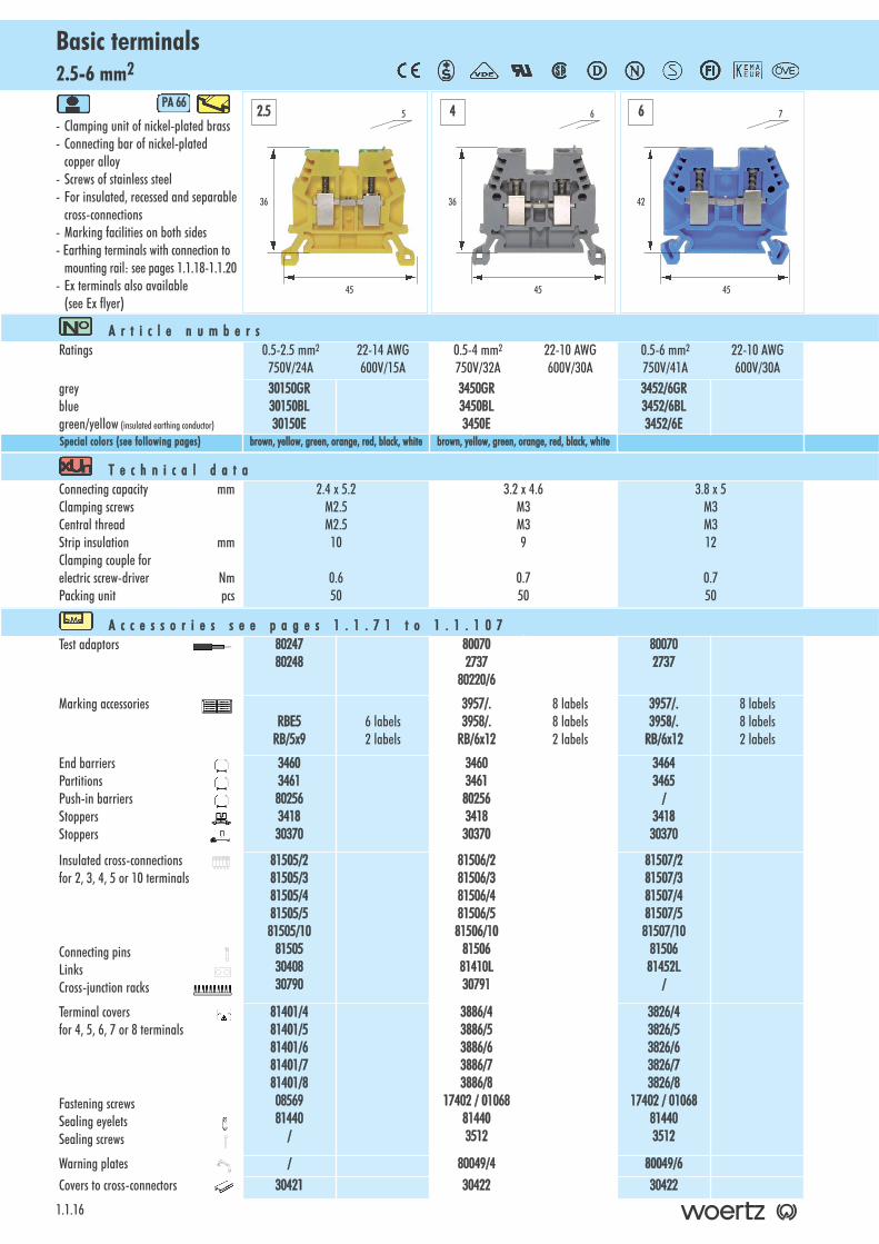
2.5-6 mm2Basic terminals
1.1.16
- Clamping unit of nickel-plated brass - Connecting bar of nickel-plated
copper alloy- Screws of stainless steel- For insulated, recessed and separable
cross-connections- Marking facilities on both sides- Earthing terminals with connection to
mounting rail: see pages 1.1.18-1.1.20- Ex terminals also available
(see Ex flyer)
PA 666
A r t i c l e nn u m b e r sRatings 0.5-2.5 mm2 22-14 AWG
750V/24A 600V/15A0.5-4 mm2 22-10 AWG750V/32A 600V/30A
0.5-6 mm2 22-10 AWG750V/41A 600V/30A
greybluegreen/yellow (insulated earthing conductor)
30150GR30150BL30150E
3450GR3450BL3450E
3452/6GR3452/6BL3452/6E
Special ccolors ((see ffollowing ppages) brown, yyellow, ggreen, oorange, rred, bblack, wwhite brown, yyellow, ggreen, oorange, rred, bblack, wwhite
T e c h n i c a l dd a t aConnecting capacity mmClamping screwsCentral threadStrip insulation mmClamping couple for electric screw-driver NmPacking unit pcs
2.4 x 5.2M2.5M2.510
0.650
3.2 x 4.6M3M39
0.750
3.8 x 5M3M312
0.750
A c c e s s o r i e s ss e e pp a g e s 11 . 1 . 7 1 tt o 11 . 1 . 1 0 7Test adaptors 80247
80248800702737
80220/6
800702737
Marking accessoriesRBE5
RB/5x96 labels2 labels
3957/.3958/.
RB/6x12
8 labels8 labels2 labels
3957/.3958/.
RB/6x12
8 labels8 labels2 labels
End barriersPartitionsPush-in barriersStoppersStoppers
3460346180256341830370
3460346180256341830370
34643465
/341830370
Insulated cross-connectionsfor 2, 3, 4, 5 or 10 terminals
Connecting pinsLinks Cross-junction racks
81505/281505/381505/481505/581505/10
815053040830790
81506/281506/381506/481506/581506/10
8150681410L30791
81507/281507/381507/481507/581507/10
8150681452L
/
Terminal covers for 4, 5, 6, 7 or 8 terminals
Fastening screws Sealing eyelets Sealing screws
81401/481401/581401/681401/781401/80856981440
/
3886/43886/53886/63886/73886/8
17402 // 001068814403512
3826/43826/53826/63826/73826/8
17402 // 001068814403512
Warning plates / 80049/4 80049/6Covers to cross-connectors 30421 30422 30422
36
45
5
36
45
62.5 4 6
42
45
7
10+16 mm2Basic terminals
- Clamping unit of nickel-plated brass - Connecting bar of nickel-plated
copper alloy- Screws of stainless steel- For insulated, recessed and separable
cross-connections- Marking facilities on both sides- Earthing terminals with connection to
mounting rail: see pages 1.1.18-1.1.20- Ex terminals also available
(see Ex flyer)
PA 666
1.1.17
A r t i c l e nn u m b e r sRatings 0.5-10 mm2 18-8 AWG
750V/57A 600V/50A2.5-16 mm2 14-4 AWG750V/76A 600V/85A
greybluegreen/yellow (insulated earthing conductor)
3452/10GR3452/10BL3452/10E
3452/16GR3452/16BL3452/16E
T e c h n i c a l dd a t aConnecting capacity mmClamping screwsCentral threadStrip insulation mmClamping couple for electric screw-driver NmPacking unit pcs
4.8 x 5.2M4M313
1.550
6.5 x 6.8M5M413
2.150
A c c e s s o r i e s ss e e pp a g e s 11 . 1 . 7 1 tt o 11 . 1 . 1 0 7Test adaptors 80070
273780071
Marking accessories 3957/.3958/.
RB/6x12
8 labels8 labels2 labels
3957/.3958/.
RB/6x12
8 labels8 labels2 labels
End barriersPartitionsStoppersStoppers
34643465341830370
34643465341830370
Insulated cross-connectionsfor 2, 3, 4, 5 or 10 terminals
Connecting pinsLinks Cross-junction racks
81508/281508/381508/481508/581508/10
8150881412L30792
81541/281541/381541/481541/581541/10
8154181414L
/
Terminal covers for 4, 5, 6, 7 or 8 terminals
Fastening screws Sealing eyelets Sealing screws
3887/43887/53887/63887/73887/801068814403512
3868/43868/53868/63868/73868/80116281441
/
Warning plates 80049/10 80049/16Covers to cross-connectors 30422 /
42
45
8
42
45
1110 16
Color terminals
The basic terminals 2.5 and 4 mm2 ofthis series are also available in follow-ing colors
Basic terminals 2.5 mm2
brown 30150BRyellow 30150GEgreen 30150GNorange 30150ORred 30150ROblack 30150SWwhite 30150WE
Basic terminals 4 mm2
brown 3450BRyellow 3450GEgreen 3450GNorange 3450ORred 3450ROblack 3450SWwhite 3450WE
As the current-carrying capacity of aseparately laid conductor may behigher than the one of the same con-ductor within a cable loom, the testinglaboratories don’t attribute anymorea fixed value but make the permissi-ble load dependent on the cable lay-ing technique.
Technicalinformation
2
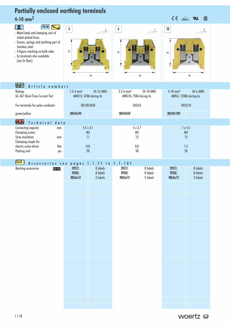
4-10 mm2Partially enclosed earthing terminals
1.1.18
- Metal body and clamping unit of nickel-plated brass
- Screws, springs and earthing part of stainless steel
- 4-figure marking on both sides- Ex terminals also available
(see Ex flyer)
PA 666
A r t i c l e nn u m b e r sRatingsUL 467 Short-Time Current Test
For terminals for polar conductor
1.5-4 mm2 24-12 AWGAWG12, 470A during 4s.
30150/3450
2.5-6 mm2 24-10 AWGAWG10, 750A during 4s.
3452/6
4-10 mm2 24-6 AWGAWG6, 1530A during 6s.
3452/10
green/yellow 30544/4V 30544/6V 30544/10V
T e c h n i c a l dd a t aConnecting capacity mmClamping screwsStrip insulation mmClamping couple for electric screw-driver NmPacking unit pcs
4.5 x 3.1M311
0.850
5 x 3.7M312
0.850
7 x 4.5M412
1.550
A c c e s s o r i e s ss e e pp a g e s 11 . 1 . 7 1 tt o 11 . 1 . 1 0 7Marking accessories 3957/.
3958/.RB/6x12
8 labels8 labels2 labels
3957/.3958/.
RB/6x12
8 labels8 labels2 labels
3957/.3958/.
RB/6x12
8 labels8 labels2 labels
4 6 10
35
48
6
39
48
7
42
48
8
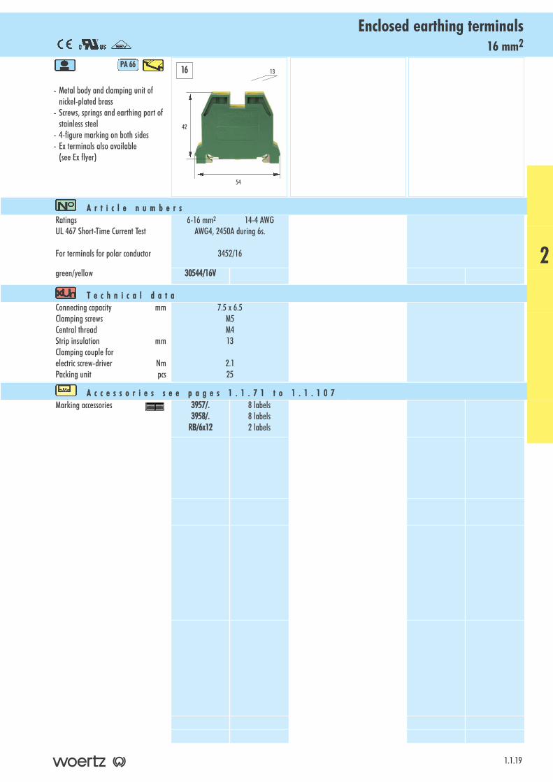
16 mm2Enclosed earthing terminals
- Metal body and clamping unit of nickel-plated brass
- Screws, springs and earthing part of stainless steel
- 4-figure marking on both sides- Ex terminals also available
(see Ex flyer)
PA 666
1.1.19
A r t i c l e nn u m b e r sRatingsUL 467 Short-Time Current Test
For terminals for polar conductor
6-16 mm2 14-4 AWGAWG4, 2450A during 6s.
3452/16
green/yellow 30544/16V
T e c h n i c a l dd a t aConnecting capacity mmClamping screwsCentral threadStrip insulation mmClamping couple for electric screw-driver NmPacking unit pcs
7.5 x 6.5M5M413
2.125
A c c e s s o r i e s ss e e pp a g e s 11 . 1 . 7 1 tt o 11 . 1 . 1 0 7Marking accessories 3957/.
3958/.RB/6x12
8 labels8 labels2 labels
42
54
1316
2

4-16 mm2Bare earthing terminals with 1 terminal clamp
1.1.20
- Terminal of brass- Screws and springs of stainless steel- The connection between mounting rail
and terminal as well as the connected conductors are protected against working loose
A r t i c l e nn u m b e r sRatings
For terminals for polar conductor
1.5-4 mm2
3450
2.5-6 mm2
3452/6
6-16 mm2
3452/16
bare 30371 30372 30373
T e c h n i c a l dd a t aConnecting capacity mmClamping screwsRail screwsStrip insulation mmClamping couple for electric screw-driverfor clamping screws Nmfor rail screws NmPacking unit pcs
4 x 3.2M3M310
0.80.850
4 x 5M4M411
1.51.050
7 x 5.8M4M411
1.51.550
A c c e s s o r i e s ss e e pp a g e s 11 . 1 . 7 1 tt o 11 . 1 . 1 0 7
4 6 16
30
50
6
32
50
7
36
50
8

2.5+4 mm2Y-terminals
- Clamping unit of nickel-plated brass - Connecting bar of nickel-plated
copper alloy- Screws of stainless steel- For insulated, recessed and separable
cross-connections- Marking facilities on both sides- Ex terminals also available
(see Ex flyer)
PA 666
1.1.21
A r t i c l e nn u m b e r sRatings 0.5-2.5 mm2 18-14 AWG
800V/24A 600V/15A0.5-4 mm2 18-12 AWG800V/32A 600V/20A
greyblue
30903GR30903BL
30904GR30904BL
T e c h n i c a l dd a t aConnecting capacity mmClamping screwsCentral threadStrip insulation mmClamping couple for electric screw-driver NmPacking unit pcs
2.5 x 3.2M2.5M2.5
9
0.550
3.2 x 4.6M3M39
0.750
A c c e s s o r i e s ss e e pp a g e s 11 . 1 . 7 1 tt o 11 . 1 . 1 0 7Test adaptors 80247
80248800702737
Marking accessories RBE5RB/5x9
6 labels2 labels
3957/.3958/.RB/6x9
6 labels6 labels2 labels
End barriersStoppers
309133418
309133418
Insulated cross-connectionsfor 2, 3, 4, 5 or 10 terminals
Connecting pinsLinks Cross-junction racks
81505/281505/381505/481505/581505/10
815053040830790
81506/281506/381506/481506/581506/10
8150681410L30791
Terminal covers for 4, 5, 6, 7 or 8 terminals
Fastening screws Sealing eyelets
81401/481401/581401/681401/781401/80856981440
3886/43886/53886/63886/73886/8
17402 // 00106881440
Covers to cross-connectors 30421 30422
41.6
52
5
41.6
52
62.5 4
2
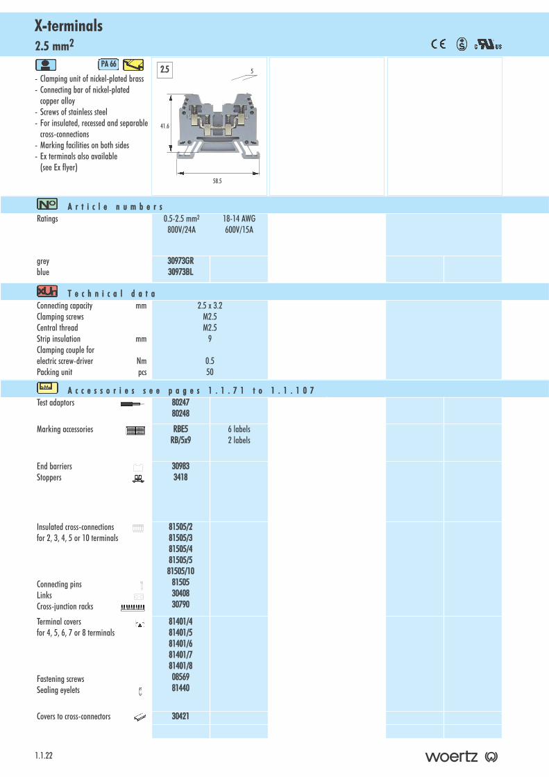
2.5 mm2X-terminals
1.1.22
- Clamping unit of nickel-plated brass - Connecting bar of nickel-plated
copper alloy- Screws of stainless steel- For insulated, recessed and separable
cross-connections- Marking facilities on both sides- Ex terminals also available
(see Ex flyer)
PA 666
A r t i c l e nn u m b e r sRatings 0.5-2.5 mm2 18-14 AWG
800V/24A 600V/15A
greyblue
30973GR30973BL
T e c h n i c a l dd a t aConnecting capacity mmClamping screwsCentral threadStrip insulation mmClamping couple for electric screw-driver NmPacking unit pcs
2.5 x 3.2M2.5M2.5
9
0.550
A c c e s s o r i e s ss e e pp a g e s 11 . 1 . 7 1 tt o 11 . 1 . 1 0 7Test adaptors 80247
80248
Marking accessories RBE5RB/5x9
6 labels2 labels
End barriersStoppers
309833418
Insulated cross-connections for 2, 3, 4, 5 or 10 terminals
Connecting pinsLinks Cross-junction racks
81505/281505/381505/481505/581505/10
815053040830790
Terminal covers for 4, 5, 6, 7 or 8 terminals
Fastening screws Sealing eyelets
81401/481401/581401/681401/781401/80856981440
Covers to cross-connectors 30421
2.5
41.6
58.5
5
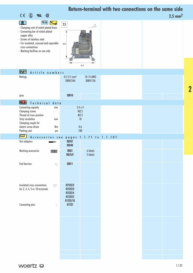
2.5 mm2Return-terminal with two connections on the same side
- Clamping unit of nickel-plated brass - Connecting bar of nickel-plated
copper alloy- Screws of stainless steel- For insulated, recessed and separable
cross-connections- Marking facilities on one side
PA 666
1.1.23
A r t i c l e nn u m b e r sRatings 0.5-2.5 mm2 18-14 AWG
500V/24A 300V/15A
grey 30810
T e c h n i c a l dd a t aConnecting capacity mmClamping screwsThread of cross-junctionStrip insulation mmClamping couple for electric screw-driver NmPacking unit pcs
2.4 x 4M2.5M2.510
0.6100
A c c e s s o r i e s ss e e pp a g e s 11 . 1 . 7 1 tt o 11 . 1 . 1 0 7Test adaptors 80247
80248
Marking accessories RBE5RB/5x9
6 labels2 labels
End barriers 30811
Insulated cross-connectionsfor 2, 3, 4, 5 or 10 terminals
Connecting pins
81525/281525/381525/481525/581525/10
81525
50.5
45.3
52.5
2
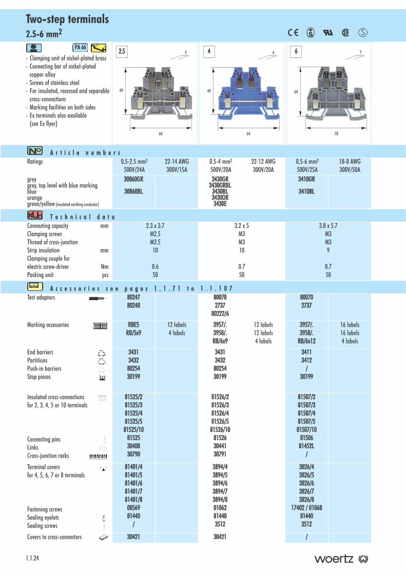
2.5-6 mm2Two-step terminals
1.1.24
- Clamping unit of nickel-plated brass - Connecting bar of nickel-plated
copper alloy- Screws of stainless steel- For insulated, recessed and separable
cross-connections- Marking facilities on both sides- Ex terminals also available
(see Ex flyer)
PA 666
A r t i c l e nn u m b e r sRatings 0.5-2.5 mm2 22-14 AWG
500V/24A 300V/15A0.5-4 mm2 22-12 AWG500V/20A 300V/20A
0.5-6 mm2 18-8 AWG500V/25A 300V/50A
greygrey, top level with blue markingblueorangegreen/yellow (insulated earthing conductor)
30860GR
30860BL
3430GR3430GRBL
3430BL3430OR3430E
3410GR
3410BL
T e c h n i c a l dd a t aConnecting capacity mmClamping screwsThread of cross-junctionStrip insulation mmClamping couple for electric screw-driver NmPacking unit pcs
2.3 x 3.7M2.5M2.510
0.650
3.2 x 5M3M310
0.750
3.8 x 5.7M3M39
0.750
A c c e s s o r i e s ss e e pp a g e s 11 . 1 . 7 1 tt o 11 . 1 . 1 0 7Test adaptors 80247
80248800702737
80222/6
800702737
Marking accessories RBE5RB/5x9
12 labels4 labels
3957/.3958/.RB/6x9
12 labels12 labels4 labels
3957/.3958/.
RB/6x12
16 labels16 labels4 labels
End barriersPartitionsPush-in barriersStop pieces
343134328025430199
343134328025430199
34113412
/30199
Insulated cross-connectionsfor 2, 3, 4, 5 or 10 terminals
Connecting pinsLinksCross-junction racks
81525/281525/381525/481525/581525/10
815253040830790
81526/281526/381526/481526/581526/10
815263044130791
81507/281507/381507/481507/581507/10
8150681452L
/
Terminal covers for 4, 5, 6, 7 or 8 terminals
Fastening screws Sealing eyelets Sealing screws
81401/481401/581401/681401/781401/80856981440
/
3894/43894/53894/63894/73894/801062814403512
3826/43826/53826/63826/73826/8
17402 // 001068814403512
Covers to cross-connectors 30421 30421 /
2.5 4 6
49
64
5
49
64
6
64
78
7
4 mm2Two-step single-pole terminals
- Clamping unit of nickel-plated brass - Connecting bar of nickel-plated
copper alloy- Screws of stainless steel- For insulated, recessed and separable
cross-connections- Marking facilities on both sides- Top and bottom bars are connected:
the 4 connecting points at the same potential
- Ex terminals also available (see Ex flyer)
PA 666
1.1.25
A r t i c l e nn u m b e r sRatings 0.5-4 mm2 18-12 AWG
500V/20A 300V/20A
blackblue
3430/1P3430/1PBL
T e c h n i c a l dd a t aConnecting capacity mmClamping screwsThread of cross-junctionStrip insulation mmClamping couple for electric screw-driver NmPacking unit pcs
3.2 x 5M3M310
0.750
A c c e s s o r i e s ss e e pp a g e s 11 . 1 . 7 1 tt o 11 . 1 . 1 0 7Test adaptors 80070
273780222/6
Marking accessories 3957/.3958/.RB/6x9
12 labels12 labels4 labels
End barriersPartitionsPush-in barriersStop pieces
3431 34328025430199
Insulated cross-connectionsfor 2, 3, 4, 5 or 10 terminals
Connecting pinsLinks Cross-junction racks
81526/281526/381526/481526/581526/10
815263044130791
Terminal covers for 4, 5, 6, 7 or 8 terminals
Fastening screws Sealing eyelets Sealing screws
3894/43894/53894/63894/73894/801062814403512
Covers to cross-connections 30421
49
64
64
2
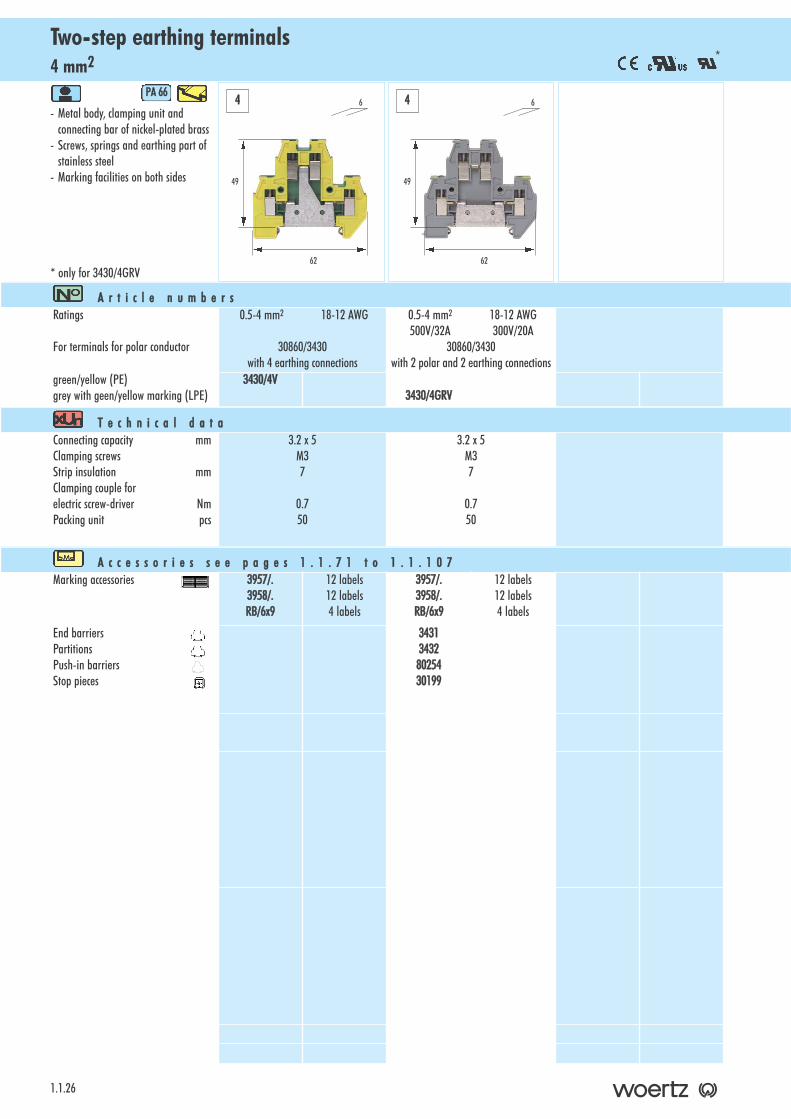
4 mm2Two-step earthing terminals
1.1.26
- Metal body, clamping unit and connecting bar of nickel-plated brass
- Screws, springs and earthing part of stainless steel
- Marking facilities on both sides
* only for 3430/4GRV
PA 666
A r t i c l e nn u m b e r sRatings
For terminals for polar conductor
0.5-4 mm2 18-12 AWG
30860/3430with 4 earthing connections
0.5-4 mm2 18-12 AWG500V/32A 300V/20A
30860/3430with 2 polar and 2 earthing connections
green/yellow (PE)grey with geen/yellow marking (LPE)
3430/4V3430/4GRV
T e c h n i c a l dd a t aConnecting capacity mmClamping screwsStrip insulation mmClamping couple for electric screw-driver NmPacking unit pcs
3.2 x 5M37
0.750
3.2 x 5M37
0.750
A c c e s s o r i e s ss e e pp a g e s 11 . 1 . 7 1 tt o 11 . 1 . 1 0 7Marking accessories 3957/.
3958/.RB/6x9
12 labels12 labels4 labels
3957/.3958/.RB/6x9
12 labels12 labels4 labels
End barriersPartitionsPush-in barriersStop pieces
343134328025430199
4 4
49
62
6
*
49
62
6
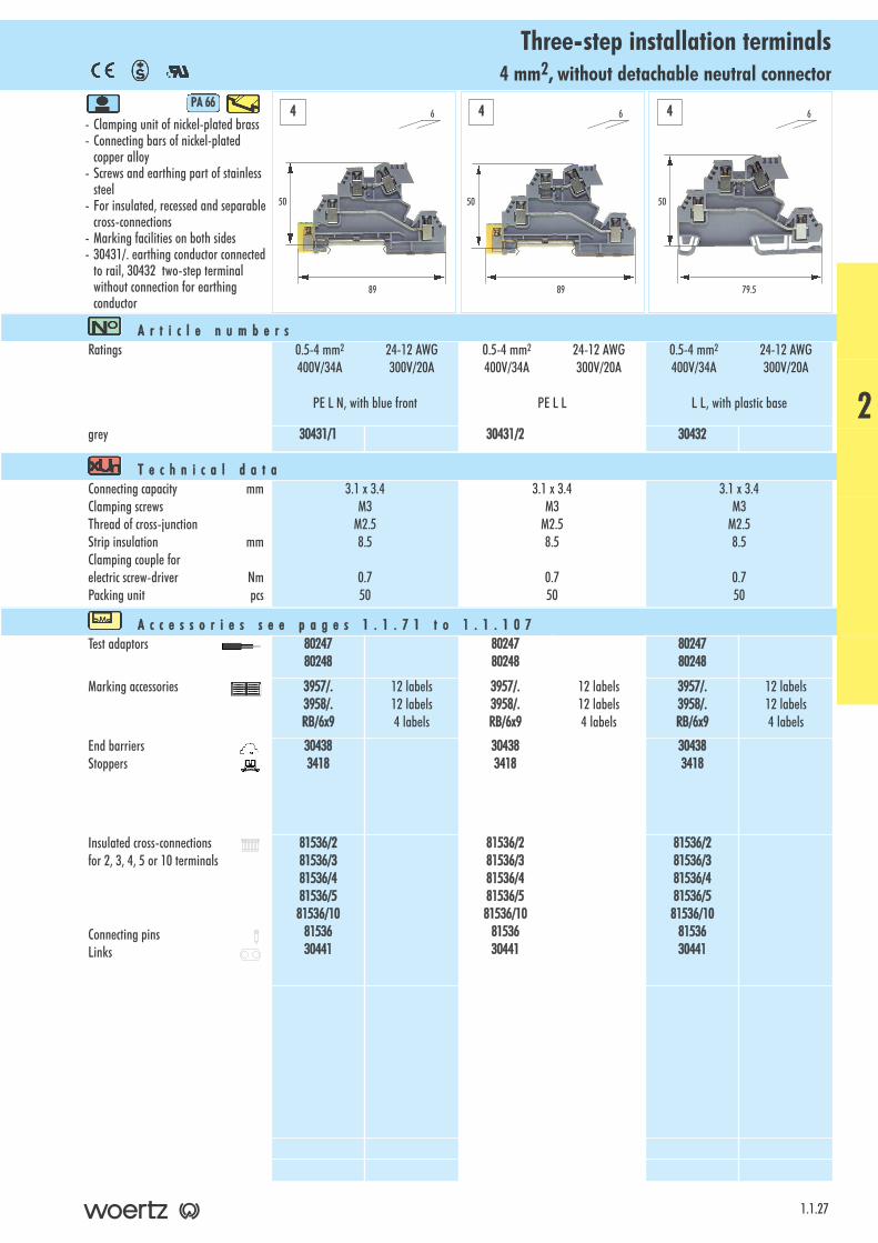
4 mm2, without detachable neutral connectorThree-step installation terminals
- Clamping unit of nickel-plated brass - Connecting bars of nickel-plated
copper alloy- Screws and earthing part of stainless
steel- For insulated, recessed and separable
cross-connections- Marking facilities on both sides- 30431/. earthing conductor connected
to rail, 30432 two-step terminal without connection for earthing conductor
PA 666
1.1.27
A r t i c l e nn u m b e r sRatings 0.5-4 mm2 24-12 AWG
400V/34A 300V/20A
PE L N, with blue front
0.5-4 mm2 24-12 AWG400V/34A 300V/20A
PE L L
0.5-4 mm2 24-12 AWG400V/34A 300V/20A
L L, with plastic base
grey 30431/1 30431/2 30432
T e c h n i c a l dd a t aConnecting capacity mmClamping screwsThread of cross-junctionStrip insulation mmClamping couple for electric screw-driver NmPacking unit pcs
3.1 x 3.4M3
M2.58.5
0.750
3.1 x 3.4M3
M2.58.5
0.750
3.1 x 3.4M3
M2.58.5
0.750
A c c e s s o r i e s ss e e pp a g e s 11 . 1 . 7 1 tt o 11 . 1 . 1 0 7Test adaptors 80247
802488024780248
8024780248
Marking accessories 3957/.3958/.RB/6x9
12 labels12 labels4 labels
3957/.3958/.RB/6x9
12 labels12 labels4 labels
3957/.3958/.RB/6x9
12 labels12 labels4 labels
End barriersStoppers
304383418
304383418
304383418
Insulated cross-connectionsfor 2, 3, 4, 5 or 10 terminals
Connecting pinsLinks
81536/281536/381536/481536/581536/10
8153630441
81536/281536/381536/481536/581536/10
8153630441
81536/281536/381536/481536/581536/10
8153630441
50
89
6
50
89
6
50
79.5
64 4 4
2
4 mm2, with detachable neutral connectorThree-step installation terminal
1.1.28
- Clamping unit of nickel-plated brass - Connecting bars of nickel-plated
copper alloy- Screws and earthing part of stainless
steel- For insulated, recessed and separable
cross-connections- Marking facilities on both sides- earthing conductor connected to rail
PA 666
A r t i c l e nn u m b e r sRatings 0.5-4 mm2 24-12 AWG
400V/34A 300V/20A
PE L N, with blue front
grey 30430
T e c h n i c a l dd a t aConnecting capacity mmClamping screwsThread of cross-junctionStrip insulation mmClamping couple for electric screw-driver NmPacking unit pcs
3.1 x 3.4M3
M2.58.5
0.750
A c c e s s o r i e s ss e e pp a g e s 11 . 1 . 7 1 tt o 11 . 1 . 1 0 7Test adaptors 80247
80248
Marking accessories 3957/.3958/.RB/6x9
9 labels9 labels3 labels
End barriersStoppers
304393418
Insulated cross-connectionsfor 2, 3, 4, 5 or 10 terminals
Connecting pinsLinks
81536/281536/381536/481536/581536/10
8153630441
Busbars of tinned electrolytic copperlength 1 m10 x 2 mm10 x 3 mm
38593856
4
47.5
89
6
2.5 mm2Three-step terminal for proximity switches
- Clamping unit of nickel-plated brass - Connecting bars of nickel-plated
copper alloy- Screws of stainless steel- 4-figure marking
PA 666
1.1.29
A r t i c l e nn u m b e r sRatings 0-2.5 mm2 26-14 AWG
250V/16A 300V/10A
grey 30400
T e c h n i c a l dd a t aConnecting capacity mmClamping screwsThread of cross-junctionStrip insulation mmClamping couple for electric screw-driver NmPacking unit pcs
2.4 x 3M2.5M2.5
7
0.5100
A c c e s s o r i e s ss e e pp a g e s 11 . 1 . 7 1 tt o 11 . 1 . 1 0 7Test adaptors 80247
80248
Marking accessories RB/5x5 4 labels
End barriersStoppers
304063418
Insulated cross-connectionsfor 2, 3, 4, 5 or 10 terminals
Connecting pinsLinks
81535/281535/381535/481535/581535/10
8153530408
Cross-junction racks 20-part, red20-part, blue22-part, red22-part, blue
30413RO30413BL30414RO30414BL
44
65
5.082.5
Technicalinformation
This three-step terminal for proximityswitches which can be clipped on tomounting rail is only 5.08 mm wideand enables thus compact junctionblocks to be realized. Both lower levels are intended for the positiveand negative conductors of a proximi-ty switch; they are connected to thepower supply by means of cross-connection links.
2
2.5 mm2 - feed terminalThree-step terminal for proximity switches
1.1.30
- Clamping unit of nickel-plated brass - Connecting bars of nickel-plated
copper alloy- Screws of stainless steel- 6-figure marking
PA 666
A r t i c l e nn u m b e r sRatings 0-2.5 mm2 26-14 AWG
380V/16A 300V/10A
grey 30403
T e c h n i c a l dd a t aConnecting capacity mmClamping screwsThread of cross-junctionStrip insulation mmClamping couple for electric screw-driver NmPacking unit pcs
2.4 x 3M2.5M2.5
7
0.550
A c c e s s o r i e s ss e e pp a g e s 11 . 1 . 7 1 tt o 11 . 1 . 1 0 7Test adaptors 80247
80248
Marking accessories RB/5x5 6 labels
End barriersStoppers
304073418
Insulated cross-connectionsfor 2, 3, 4, 5 or 10 terminals
Connecting pinsLinks
81535/281535/381535/481535/581535/10
8153530408
Cross-junction racks 20-part, red20-part, blue22-part, red22-part, blue
30413RO30413BL30414RO30414BL
2.5
44
87
5.08
Technicalinformation
This special terminal is used for fee-ding a set of terminals for proximityswitches. It is meant for receiving thefeed line on the one hand and thecross-links to the terminals for proxi-mity switches on the other hand.
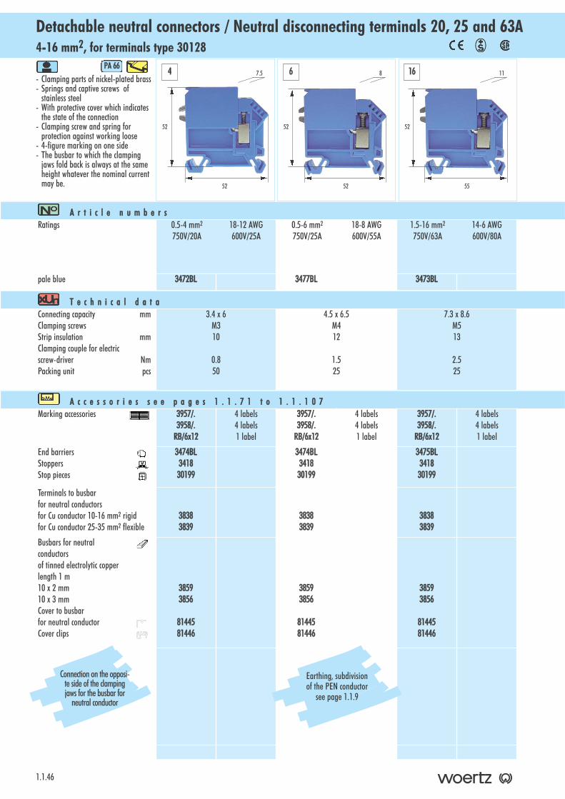
20 and 25 A, 4+6 mm2, for terminals type 30150Detachable neutral connectors/Neutral disconnecting terminals
- Clamping parts of nickel-plated brass- Screws of corrosion-resistant steel- With protective cover which indicates
the state of the connection - 4-figure marking on one side- The busbar to which the clamping
jaws fold back is at the same height in case of 4 and 6 mm2 terminals
PA 666
1.1.31
A r t i c l e nn u m b e r sRatings 0.5-4 mm2
750V/20A0.5-6 mm2
750V/25A
pale blue 30290 30291
T e c h n i c a l dd a t aConnecting capacity mmClamping screwsStrip insulation mmClamping couple for electric screw-driver NmPacking unit pcs
3.1 x 4M311
0.825
3.6 x 5M314
0.825
A c c e s s o r i e s ss e e pp a g e s 11 . 1 . 7 1 tt o 11 . 1 . 1 0 7Marking accessories 3957/.
3958/.RB/6x12
4 labels4 labels1 label
3957/.3958/.
RB/6x12
4 labels4 labels1 label
PartitionsStoppersStop pieces
30296341830199
30297 341830199
Terminals to busbar for neutral conductorsfor copper conductors 10-16mm2 rigidfor copper conductors 25-35mm2 flexible
38383839
38383839
Busbars forneutral conductorsof tinned electrolytic copperlength 1 m10 x 2 mm10 x 3 mmCovers to busbars forneutral conductorsCover clips
38593856
8144581446
38593856
8144581446
38.5
51.5
7.5
38.5
53
84 6
Connection on the opposite side of the bus-bar for neutral conductor
2
Earthing, subdivision ofthe PEN conductor:
see page 1.1.9
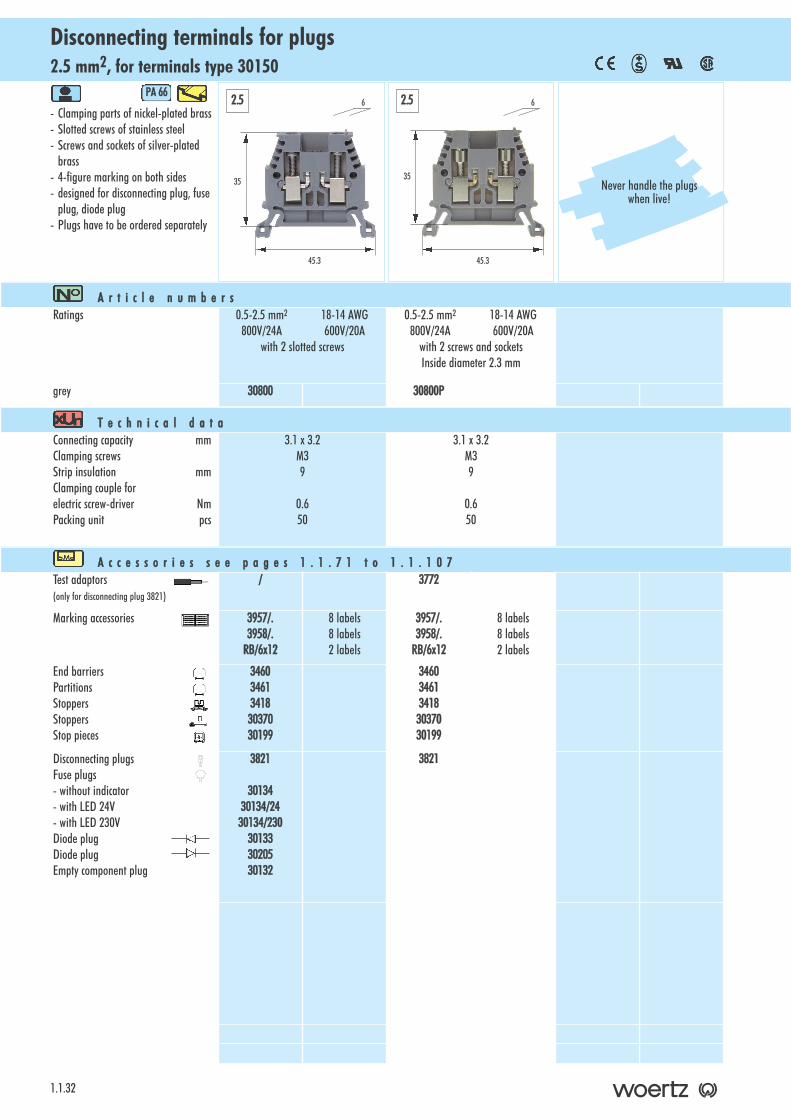
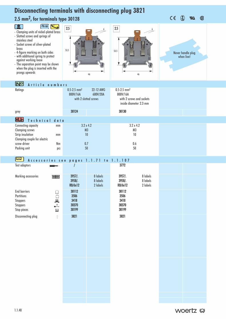
2.5 mm2, for terminals type 30150Disconnecting terminals for plugs
1.1.32
- Clamping parts of nickel-plated brass- Slotted screws of stainless steel- Screws and sockets of silver-plated
brass- 4-figure marking on both sides- designed for disconnecting plug, fuse
plug, diode plug - Plugs have to be ordered separately
PA 666
A r t i c l e nn u m b e r sRatings 0.5-2.5 mm2 18-14 AWG
800V/24A 600V/20Awith 2 slotted screws
0.5-2.5 mm2 18-14 AWG800V/24A 600V/20A
with 2 screws and sockets Inside diameter 2.3 mm
grey 30800 30800P
T e c h n i c a l dd a t aConnecting capacity mmClamping screwsStrip insulation mmClamping couple forelectric screw-driver NmPacking unit pcs
3.1 x 3.2M39
0.650
3.1 x 3.2M39
0.650
A c c e s s o r i e s ss e e pp a g e s 11 . 1 . 7 1 tt o 11 . 1 . 1 0 7Test adaptors(only for disconnecting plug 3821)
/ 3772
Marking accessories 3957/.3958/.
RB/6x12
8 labels8 labels2 labels
3957/.3958/.
RB/6x12
8 labels8 labels2 labels
End barriersPartitionsStoppersStoppersStop pieces
3460346134183037030199
3460346134183037030199
Disconnecting plugsFuse plugs - without indicator- with LED 24V- with LED 230VDiode plugDiode plugEmpty component plug
3821
3013430134/2430134/230
301333020530132
3821
2.5 2.5
35
45.3
6
35
45.3
6
Never handle the plugswhen live!
for plugs and cross-connections, 2.5 mm2, for terminals type 30150Two-step terminals with disconnecting function
- Clamping part and connecting bar of nickel-plated brass
- Screws and earthing part of stainless steel
- 2x3-figure marking on both sides- designed for disconnecting plug, fuse
plug, diode plug and for cross-connections
- Plugs and cross-connections have to be ordered separately
PA 666
1.1.33
A r t i c l e nn u m b e r sRatings 0.5-2.5 mm2 18-14 AWG
500V/24A 300V/20A
without ground connection
0.5-2.5 mm2 18-14 AWG500V/24A 300V/20A
with ground connection
grey 30890 30891
T e c h n i c a l dd a t aConnecting capacity mmClamping screwsThread of cross-junctionStrip insulation mmClamping couple for electric screw-driver NmPacking unit pcs
3.8 x 3.1M3M38
0.650
3.8 x 3.1M3M38
0.650
A c c e s s o r i e s ss e e pp a g e s 11 . 1 . 7 1 tt o 11 . 1 . 1 0 7Test adaptors(only for lower level)
800702737
800702737
Marking accessories 3957/.3958/.RB/6x9
12 labels12 labels4 labels
3957/.3958/.RB/6x9
12 labels12 labels4 labels
End barriersPartitionsStoppersStoppersStop pieces
308923089334183037030199
308923089334183037030199
Insulated cross-connectionsfor 2, 3, 4, 5 or 10 terminals
Connecting pinsLinks Cross-junction racks
81526/281526/381526/481526/581526/10
815263044130791
81526/281526/381526/481526/581526/10
815263044130791
Disconnecting plugsFuse plugs - without indicator- with LED 24V- without LED 230VDiode plugDiode plugEmpty component plug
3821
3013430134/2430134/230
301333020530132
3821
3013430134/2430134/230
301333020530132
53
67
6
54
75
62.5 2.5
Never handle the plugswhen live!
Technicalinformation
Upper level with disconnecting function and lower level for cross-con-nections
2
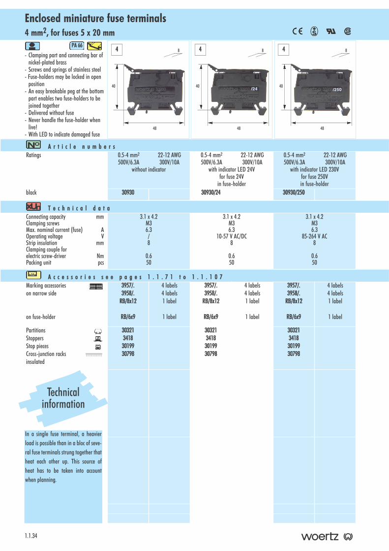
4 mm2, for fuses 5 x 20 mmEnclosed miniature fuse terminals
1.1.34
- Clamping part and connecting bar of nickel-plated brass
- Screws and springs of stainless steel- Fuse-holders may be locked in open
position- An easy breakable peg at the bottom
part enables two fuse-holders to be joined together
- Delivered without fuse- Never handle the fuse-holder when
live!- With LED to indicate damaged fuse
PA 666
A r t i c l e nn u m b e r sRatings 0.5-4 mm2 22-12 AWG
500V/6.3A 300V/10Awithout indicator
0.5-4 mm2 22-12 AWG500V/6.3A 300V/10A
with indicator LED 24Vfor fuse 24V
in fuse-holder
0.5-4 mm2 22-12 AWG500V/6.3A 300V/10A
with indicator LED 230Vfor fuse 250Vin fuse-holder
black 30930 30930/24 30930/250
T e c h n i c a l dd a t aConnecting capacity mmClamping screwsMax. nominal current (fuse) AOperating voltage VStrip insulation mmClamping couple for electric screw-driver NmPacking unit pcs
3.1 x 4.2M36.3/8
0.650
3.1 x 4.2M36.3
10-57 V AC/DC8
0.650
3.1 x 4.2M36.3
85-264 V AC8
0.650
A c c e s s o r i e s ss e e pp a g e s 11 . 1 . 7 1 tt o 11 . 1 . 1 0 7Marking accessorieson narrow side
on fuse-holder
3957/.3958/.
RB/8x12
RB/6x9
4 labels4 labels1 label
1 label
3957/.3958/.
RB/8x12
RB/6x9
4 labels4 labels1 label
1 label
3957/.3958/.
RB/8x12
RB/6x9
4 labels4 labels1 label
1 label
PartitionsStoppersStop piecesCross-junction racks insulated
3032134183019930798
3032134183019930798
3032134183019930798
40
48
84 4 4
Technicalinformation
In a single fuse terminal, a heavierload is possible than in a bloc of seve-ral fuse terminals strung together thatheat each other up. This source ofheat has to be taken into accountwhen planning.
40
48
8
40
48
8
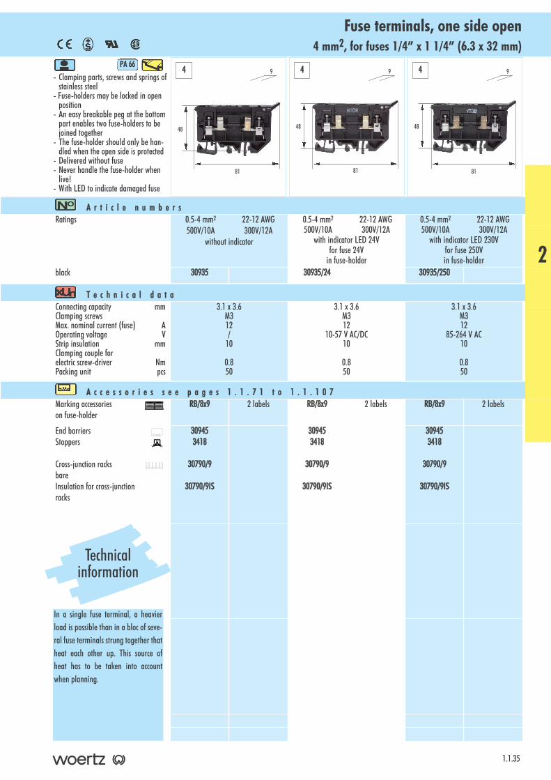
4 mm2, for fuses 1/4” x 1 1/4” (6.3 x 32 mm)Fuse terminals, one side open
- Clamping parts, screws and springs ofstainless steel
- Fuse-holders may be locked in open position
- An easy breakable peg at the bottompart enables two fuse-holders to be joined together
- The fuse-holder should only be han-dled when the open side is protected
- Delivered without fuse- Never handle the fuse-holder when
live!- With LED to indicate damaged fuse
PA 666
1.1.35
A r t i c l e nn u m b e r sRatings 0.5-4 mm2 22-12 AWG
500V/10A 300V/12Awithout indicator
0.5-4 mm2 22-12 AWG500V/10A 300V/12A
with indicator LED 24Vfor fuse 24V
in fuse-holder
0.5-4 mm2 22-12 AWG500V/10A 300V/12A
with indicator LED 230Vfor fuse 250Vin fuse-holder
black 30935 30935/24 30935/250
T e c h n i c a l dd a t aConnecting capacity mmClamping screwsMax. nominal current (fuse) AOperating voltage VStrip insulation mmClamping couple for electric screw-driver NmPacking unit pcs
3.1 x 3.6M312/
10
0.850
3.1 x 3.6M312
10-57 V AC/DC10
0.850
3.1 x 3.6M312
85-264 V AC10
0.850
A c c e s s o r i e s ss e e pp a g e s 11 . 1 . 7 1 tt o 11 . 1 . 1 0 7Marking accessorieson fuse-holder
RB/8x9 2 labels RB/8x9 2 labels RB/8x9 2 labels
End barriersStoppers
Cross-junction racksbareInsulation for cross-junctionracks
309453418
30790/9
30790/9IS
309453418
30790/9
30790/9IS
309453418
30790/9
30790/9IS
48
81
9
48
81
9
48
81
94 4 4
Technicalinformation
In a single fuse terminal, a heavierload is possible than in a bloc of seve-ral fuse terminals strung together thatheat each other up. This source ofheat has to be taken into accountwhen planning.
2
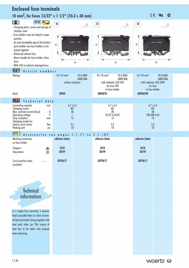
10 mm2, for fuses 13/32” x 1 1/2” (10.3 x 38 mm)Enclosed fuse terminals
1.1.36
- Clamping parts, screws and springs ofstainless steel
- Fuse-holders may be locked in open position
- An easy breakable peg at the bottompart enables two fuse-holders to be joined together
- Delivered without fuse- Never handle the fuse-holder when
live!- With LED to indicate damaged fuse
PA 666
A r t i c l e nn u m b e r sRatings 0.5-10 mm2 18-8 AWG
600V/30Awithout indicator
0.5-10 mm2 18-8 AWG600V/30A
with indicator LED 24Vfor fuse 24V
in fuse-holder
0.5-10 mm2 18-8 AWG600V/30A
with indicator LED 230Vfor fuse
in fuse-holderblack 30940 30940/24 30940/250
T e c h n i c a l dd a t aConnecting capacity mmClamping screwsMax. nominal current (fuse) AOperating voltage VStrip insulation mmClamping couple for electric screw-driver NmPacking unit pcs
6.7 x 6.2M530/
13
2.210
6.7 x 6.2M530
10-57 V AC/DC13
2.210
6.7 x 6.2M530
100-300 V AC13
2.210
A c c e s s o r i e s ss e e pp a g e s 11 . 1 . 7 1 tt o 11 . 1 . 1 0 7Marking accessorieson fuse-holder
adhesive llabels adhesive llabels adhesive llabels
StoppersStop pieces
341830199
341830199
341830199
Cross-junction racks,insulated
30790/17 30790/17 30790/17
60
88
17
60
88
17
60
88
1710 10 10
Technicalinformation
In a single fuse terminal, a heavierload is possible than in a bloc of seve-ral fuse terminals strung together thatheat each other up. This source ofheat has to be taken into accountwhen planning.
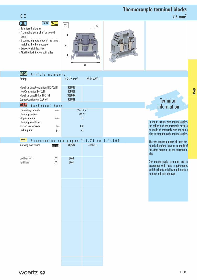
2.5 mm2Thermocouple terminal blocks
- Twin terminal, grey- 4 clamping parts of nickel-plated
brass- 2 connecting bars made of the same
metal as the thermocouple- Screws of stainless steel- Marking facilities on both sides
PA 666
1.1.37
A r t i c l e nn u m b e r sRatings 0.2-2.5 mm2 28-14 AWG
Nickel chrome/Constantan NiCr/CuNiIron/Constantan Fe/CuNiNickel chrome/Nickel NiCr/NiCopper/constantan Cu/CuNi
30880E30880J30880K30880T
T e c h n i c a l dd a t aConnecting capacity mmClamping screwsStrip insulation mmClamping couple for electric screw-driver NmPacking unit pcs
2.4 x 4.7M2.510
0.650
A c c e s s o r i e s ss e e pp a g e s 11 . 1 . 7 1 tt o 11 . 1 . 1 0 7Marking accessories RB/5x9 4 labels
End barriersPartitions
34603461
36
45
102.5
Technicalinformation
In shunt circuits with thermocouples,the cables and the terminals have tobe made of materials with the sameelectric strength as the thermocouples.
The two connecting bars of these ter-minals therefore have to be made ofthe same materials as the thermocou-ples.
Our thermocouple terminals are inaccordance with these requirements,and the character following the articlenumber indicates the type.
2

2.5-6 mm2Terminals for stringent demands
1.1.38
- Clamping parts of nickel-plated brass- Connecting bar of nickel-plated
copper alloy- Screws and springs of stainless steel- with additional springs for protection
against working loose (see picture)- For insulated, recessed and separable
cross-connections- 4-figure marking on both sides- Earthing terminals with connection to
mounting rail: see pages 1.1.41-1.1.44- Ex terminals also available
(see Ex flyer)
PA 666
A r t i c l e nn u m b e r sRatings 0.5-2.5 mm2 22-12 AWG
1000V/24A 600V/20A0.5-4 mm2 18-12 AWG1000V/32A 600V/20A
0.5-6 mm2 18-8 AWG1000V/41A 600V/50A
greybluegreen/yellow (Insulated earthing conductor)
30128GR30128BL30128E
3424GR3424BL3424E
3425GR3425BL3425E
T e c h n i c a l dd a t aConnecting capacity mmClamping screwsCentral threadStrip insulation mmClamping couple for electric screw-driver NmPacking unit pcs
3.2 x 4.2M3M310
0.750
3.4 x 6M3M310
0.750
4.5 x 6M4M311
1.550
A c c e s s o r i e s ss e e pp a g e s 11 . 1 . 7 1 tt o 11 . 1 . 1 0 7Test adaptors 80070
2737800702737
800702737
Marking accessories 3957/.3958/.
RB/6x12
8 labels8 labels2 labels
3957/.3958/.
RB/6x12
8 labels8 labels2 labels
3957/.3958/.
RB/6x12
8 labels8 labels2 labels
End barriersPartitionsPush-in barriersStoppersStoppersStop pieces
3011235068025534183037030199
351635068025534183037030199
351635068025534183037030199
Insulated cross-connectionsfor 2, 3, 4, 5 or 10 terminals
Connecting pinsLinks Cross-junction racks
81546/281546/381546/481546/581546/10
8154681410L30790
81556/281556/381556/481556/581556/10
8155681410L30791
81548/281548/381548/481548/581548/10
8154881412L30792
Terminal covers for 4, 5, 6, 7 or 8 terminals
Fastening screws Sealing eyeletsSealing screws
81427814288142981430814311740281440
/
3886/43886/53886/63886/73886/801068814403512
3887/43887/53887/63887/73887/801068814403512
Covers to cross-connectors 30422 30422 30422
43
46
6
EN 60947-7-1
2.5 4 6
45
49
6
45
49
8
additionalspring
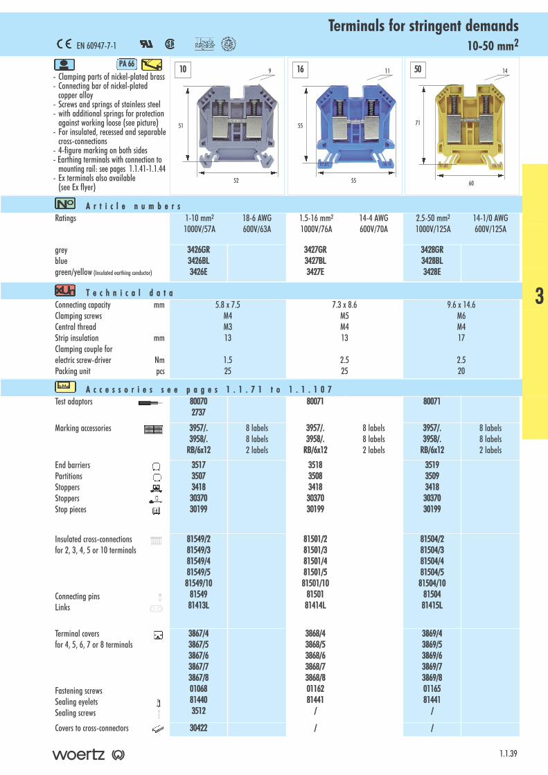
10-50 mm2Terminals for stringent demands
- Clamping parts of nickel-plated brass- Connecting bar of nickel-plated
copper alloy- Screws and springs of stainless steel- with additional springs for protection
against working loose (see picture)- For insulated, recessed and separable
cross-connections- 4-figure marking on both sides- Earthing terminals with connection to
mounting rail: see pages 1.1.41-1.1.44- Ex terminals also available
(see Ex flyer)
PA 666
1.1.39
A r t i c l e nn u m b e r sRatings 1-10 mm2 18-6 AWG
1000V/57A 600V/63A1.5-16 mm2 14-4 AWG1000V/76A 600V/70A
2.5-50 mm2 14-1/0 AWG1000V/125A 600V/125A
greybluegreen/yellow (Insulated earthing conductor)
3426GR3426BL3426E
3427GR3427BL3427E
3428GR3428BL3428E
T e c h n i c a l dd a t aConnecting capacity mmClamping screwsCentral threadStrip insulation mmClamping couple for electric screw-driver NmPacking unit pcs
5.8 x 7.5M4M313
1.525
7.3 x 8.6M5M413
2.525
9.6 x 14.6M6M417
2.520
A c c e s s o r i e s ss e e pp a g e s 11 . 1 . 7 1 tt o 11 . 1 . 1 0 7Test adaptors 80070
273780071 80071
Marking accessories 3957/.3958/.
RB/6x12
8 labels8 labels2 labels
3957/.3958/.
RB/6x12
8 labels8 labels2 labels
3957/.3958/.
RB/6x12
8 labels8 labels2 labels
End barriersPartitionsStoppersStoppersStop pieces
3517350734183037030199
3518350834183037030199
3519350934183037030199
Insulated cross-connectionsfor 2, 3, 4, 5 or 10 terminals
Connecting pinsLinks
81549/281549/381549/481549/581549/10
8154981413L
81501/281501/381501/481501/581501/10
8150181414L
81504/281504/381504/481504/581504/10
8150481415L
Terminal covers for 4, 5, 6, 7 or 8 terminals
Fastening screws Sealing eyelets Sealing screws
3867/43867/53867/63867/73867/801068814403512
3868/43868/53868/63868/73868/80116281441
/
3869/43869/53869/63869/73869/80116581441
/
Covers to cross-connectors 30422 / /
51
52
9
EN 60947-7-1
55
55
11
71
60
1410 16 50
3
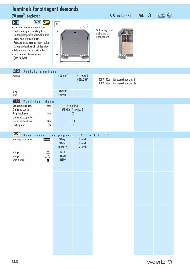
70 mm2, enclosedTerminals for stringent demands
1.1.40
- Clamping screws and springs for protection against working loose
- Rectangular profile of nickel-plated brass with 2 pressure parts
- Pressure parts, sprung captive Allen screws and springs of stainless steel
- 4-figure marking on both sides- Ex terminals also available
(see Ex flyer)
PA 666
A r t i c l e nn u m b e r sRatings 4-70 mm2 4-3/0 AWG
* 600V/200A * 1000V/192A for overvoltage class III830V/192A for overvoltage class IV
greyblue
3429GR3429BL
T e c h n i c a l dd a t aConnecting capacity mmClamping screwsStrip insulation mmClamping couple for electric screw-driver NmPacking unit pcs
14.5 x 14.5M8 Allen / key size 6
26
15.010
A c c e s s o r i e s ss e e pp a g e s 11 . 1 . 7 1 tt o 11 . 1 . 1 0 7Marking accessories 3957/.
3958/.RB/6x12
8 labels8 labels2 labels
StoppersStoppersStop pieces
34183037030199
71
74
23
EN 60947-7-1
70
With through brassprofile and 2pressure parts

4-10 mm2, for terminals type 30128Enclosed earthing terminals for stringent demands
- Terminal and pressure part of brass - Screws and springs of stainless steel- 4-figure marking on both sides - The connection between mounting rail
and terminal as well as the connected conductors are protected against working loose
- Ex terminals also available (see Ex flyer)
PA 666
1.1.41
A r t i c l e nn u m b e r sRatings
For terminals for polar conductors
1.5-4 mm2 18-12 AWG
3424
2.5-6 mm2 18-8 AWG
3425
4-10 mm2 16-6 AWG
3426
green/yellow 3436/4V 3436V 3436/10V
T e c h n i c a l dd a t aConnecting capacity ∅ mmClamping screwsCentral screw of pressure partStrip insulation mmClamping couple for electric screw-driverfor clamping screws Nmfor central screw NmPacking unit pcs
3.1M3M312
0.80.750
3.7M3M312
0.80.750
5.3M4M412
1.81.225
A c c e s s o r i e s ss e e pp a g e s 11 . 1 . 7 1 tt o 11 . 1 . 1 0 7Marking accessories 3957/.
3958/.RB/6x12
8 labels8 labels2 labels
3957/.3958/.
RB/6x12
8 labels8 labels2 labels
3957/.3958/.
RB/6x12
8 labels8 labels2 labels
Thanks to the enclosure, the earthingterminal shows the same outlines asthe terminal for polar conductor ofsame cross-section The earthing terminal in the enclosure is similar to No.identical to No.
3435 3436 3436/10
45
49
8
45
49
9
50.5
52
114 6 10
3
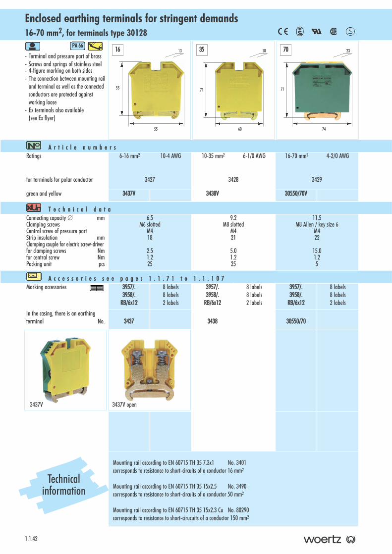
16-70 mm2, for terminals type 30128Enclosed earthing terminals for stringent demands
1.1.42
- Terminal and pressure part of brass - Screws and springs of stainless steel- 4-figure marking on both sides- The connection between mounting rail
and terminal as well as the connected conductors are protected against working loose
- Ex terminals also available (see Ex flyer)
PA 666
A r t i c l e nn u m b e r sRatings
for terminals for polar conductor
6-16 mm2 10-4 AWG
3427
10-35 mm2 6-1/0 AWG
3428
16-70 mm2 4-2/0 AWG
3429
green and yellow 3437V 3438V 30550/70V
T e c h n i c a l dd a t aConnecting capacity ∅ mmClamping screwsCentral screw of pressure partStrip insulation mmClamping couple for electric screw-driverfor clamping screws Nmfor central screw NmPacking unit pcs
6.5M6 slotted
M418
2.51.225
9.2M8 slotted
M421
5.01.225
11.5M8 Allen / key size 6
M422
15.01.25
A c c e s s o r i e s ss e e pp a g e s 11 . 1 . 7 1 tt o 11 . 1 . 1 0 7Marking accessories 3957/.
3958/.RB/6x12
8 labels8 labels2 labels
3957/.3958/.
RB/6x12
8 labels8 labels2 labels
3957/.3958/.
RB/6x12
8 labels8 labels2 labels
In the casing, there is an earthingterminal No. 3437 3438 30550/70
Mounting rail according to EN 60715 TH 35 7.3x1 No. 3401corresponds to resistance to short-circuits of a conductor 16 mm2
Mounting rail according to EN 60715 TH 35 15x2.5 No. 3490corresponds to resistance to short-circuits of a conductor 50 mm2
Mounting rail according to EN 60715 TH 35 15x2.3 Cu No. 80290corresponds to resistance to short-cirucuits of a conductor 150 mm2
55
55
1316 35 70
71
60
18
71
74
23
3437V open3437V
Technicalinformation
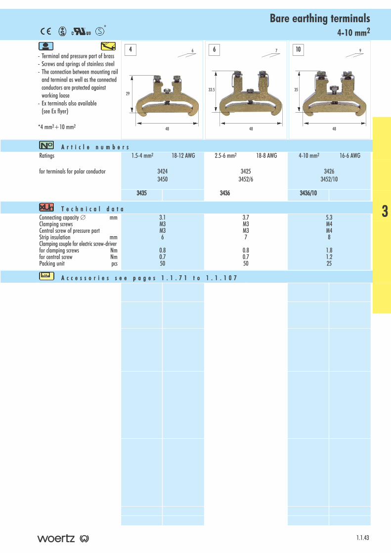
4-10 mm2Bare earthing terminals
- Terminal and pressure part of brass- Screws and springs of stainless steel- The connection between mounting rail
and terminal as well as the connected conductors are protected against working loose
- Ex terminals also available (see Ex flyer)
*4 mm2+10 mm2
1.1.43
A r t i c l e nn u m b e r sRatings
for terminals for polar conductor
1.5-4 mm2 18-12 AWG
34243450
2.5-6 mm2 18-8 AWG
34253452/6
4-10 mm2 16-6 AWG
34263452/10
3435 3436 3436/10
T e c h n i c a l dd a t aConnecting capacity ∅ mmClamping screwsCentral screw of pressure partStrip insulation mmClamping couple for electric screw-driverfor clamping screws Nmfor central screw NmPacking unit pcs
3.1M3M36
0.80.750
3.7M3M37
0.80.750
5.3M4M48
1.81.225
A c c e s s o r i e s ss e e pp a g e s 11 . 1 . 7 1 tt o 11 . 1 . 1 0 7
29
48
6
33.5
48
7
35
48
94 6 10
*
3
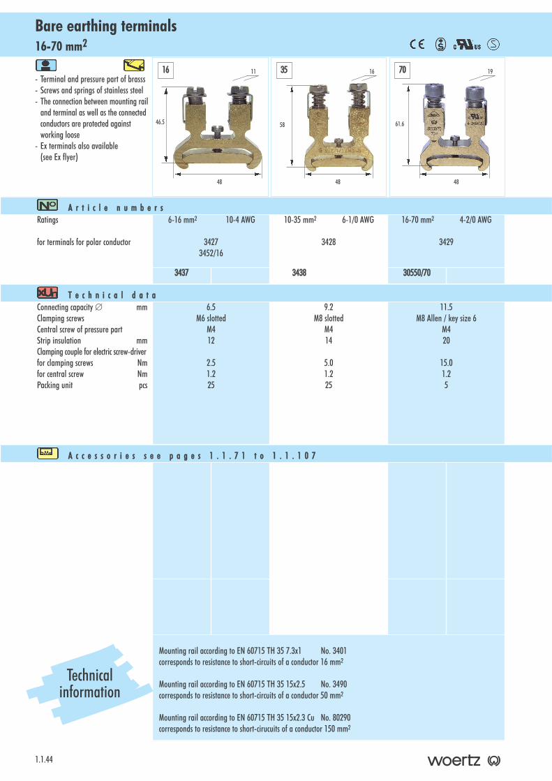
16-70 mm2Bare earthing terminals
1.1.44
- Terminal and pressure part of brasss- Screws and springs of stainless steel- The connection between mounting rail
and terminal as well as the connected conductors are protected against working loose
- Ex terminals also available (see Ex flyer)
A r t i c l e nn u m b e r sRatings
for terminals for polar conductor
6-16 mm2 10-4 AWG
34273452/16
10-35 mm2 6-1/0 AWG
3428
16-70 mm2 4-2/0 AWG
3429
3437 3438 30550/70
T e c h n i c a l dd a t aConnecting capacity ∅ mmClamping screwsCentral screw of pressure partStrip insulation mmClamping couple for electric screw-driverfor clamping screws Nmfor central screw NmPacking unit pcs
6.5M6 slotted
M412
2.51.225
9.2M8 slotted
M414
5.01.225
11.5M8 Allen / key size 6
M420
15.01.25
A c c e s s o r i e s ss e e pp a g e s 11 . 1 . 7 1 tt o 11 . 1 . 1 0 7
Mounting rail according to EN 60715 TH 35 7.3x1 No. 3401corresponds to resistance to short-circuits of a conductor 16 mm2
Mounting rail according to EN 60715 TH 35 15x2.5 No. 3490corresponds to resistance to short-circuits of a conductor 50 mm2
Mounting rail according to EN 60715 TH 35 15x2.3 Cu No. 80290corresponds to resistance to short-cirucuits of a conductor 150 mm2
46.5
48
1116 35 70
58
48
16
61.6
48
19
Technicalinformation
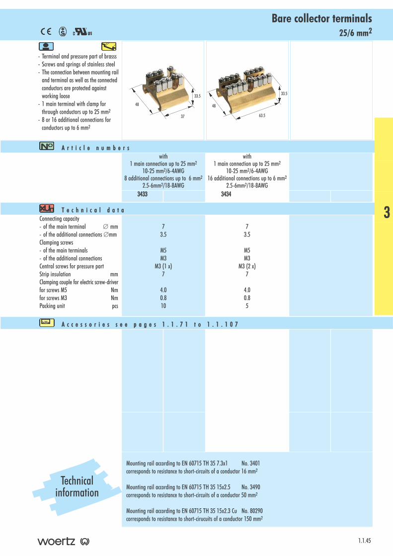
25/6 mm2Bare collector terminals
- Terminal and pressure part of brasss- Screws and springs of stainless steel- The connection between mounting rail
and terminal as well as the connected conductors are protected against working loose
- 1 main terminal with clamp forthrough conductors up to 25 mm2
- 8 or 16 additional connections forconductors up to 6 mm2
1.1.45
A r t i c l e nn u m b e r swith
1 main connection up to 25 mm2
10-25 mm2/6-4AWG8 additional connections up to 6 mm2
2.5-6mm2/18-8AWG
with1 main connection up to 25 mm2
10-25 mm2/6-4AWG16 additional connections up to 6 mm2
2.5-6mm2/18-8AWG3433 3434
T e c h n i c a l dd a t aConnecting capacity- of the main terminal ∅ mm- of the additional connections ∅mmClamping screws- of the main terminals- of the additional connectionsCentral screws for pressure partStrip insulation mmClamping couple for electric screw-driverfor screws M5 Nmfor screws M3 NmPacking unit pcs
73.5
M5M3
M3 (1 x)7
4.00.810
73.5
M5M3
M3 (2 x)7
4.00.85
A c c e s s o r i e s ss e e pp a g e s 11 . 1 . 7 1 tt o 11 . 1 . 1 0 7
Mounting rail according to EN 60715 TH 35 7.3x1 No. 3401corresponds to resistance to short-circuits of a conductor 16 mm2
Mounting rail according to EN 60715 TH 35 15x2.5 No. 3490corresponds to resistance to short-circuits of a conductor 50 mm2
Mounting rail according to EN 60715 TH 35 15x2.3 Cu No. 80290corresponds to resistance to short-cirucuits of a conductor 150 mm2
33.5
48
3
37
33.5
48
63.5
Technicalinformation
4-16 mm2, for terminals type 30128Detachable neutral connectors / Neutral disconnecting terminals 20, 25 and 63A
1.1.46
- Clamping parts of nickel-plated brass- Springs and captive screws of
stainless steel- With protective cover which indicates
the state of the connection- Clamping screw and spring for
protection against working loose- 4-figure marking on one side- The busbar to which the clamping
jaws fold back is always at the same height whatever the nominal current may be.
PA 666
A r t i c l e nn u m b e r sRatings 0.5-4 mm2 18-12 AWG
750V/20A 600V/25A0.5-6 mm2 18-8 AWG750V/25A 600V/55A
1.5-16 mm2 14-6 AWG750V/63A 600V/80A
pale blue 3472BL 3477BL 3473BL
T e c h n i c a l dd a t aConnecting capacity mmClamping screwsStrip insulation mmClamping couple for electricscrew-driver NmPacking unit pcs
3.4 x 6M310
0.850
4.5 x 6.5M412
1.525
7.3 x 8.6M513
2.525
A c c e s s o r i e s ss e e pp a g e s 11 . 1 . 7 1 tt o 11 . 1 . 1 0 7Marking accessories 3957/.
3958/.RB/6x12
4 labels4 labels1 label
3957/.3958/.
RB/6x12
4 labels4 labels1 label
3957/.3958/.
RB/6x12
4 labels4 labels1 label
End barriersStoppersStop pieces
3474BL3418 30199
3474BL3418 30199
3475BL3418 30199
Terminals to busbarfor neutral conductorsfor Cu conductor 10-16 mm2 rigidfor Cu conductor 25-35 mm2 flexible
38383839
38383839
38383839
Busbars for neutralconductorsof tinned electrolytic copperlength 1 m10 x 2 mm10 x 3 mmCover to busbarfor neutral conductorCover clips
38593856
8144581446
38593856
8144581446
38593856
8144581446
52
52
7.54 6 16
52
52
8
52
55
11
Connection on the opposi-te side of the clampingjaws for the busbar for
neutral conductor
Earthing, subdivision of the PEN conductor
see page 1.1.9

4-6 mm2, for terminals type 30128Detachable neutral connectors / Neutral disconnecting terminals 20 and 25A
- Clamping parts of nickel-plated brass- Springs and captive screws of
stainless steel- With protective cover which indicates
the state of the connection- Clamping screw and spring for
protection against working loose - 4-figure marking on one side- The busbar to which the clamping
jaws fold back is always at the same height whatever the nominal current may be.
PA 666
1.1.47
A r t i c l e nn u m b e r sRatings 0.5-4 mm2 18-12 AWG
750V/20A 600V/25A0.5-6 mm2 18-8 AWG750V/25A 600V/55A
pale blue 30197 30200
T e c h n i c a l dd a t aConnecting capacity mmClamping screwsStrip insulation mmClamping couple for electricscrew-driver NmPacking unit pcs
3.4 x 6M3
15.5
0.850
4.5 x 6.5M4
15.5
1.525
A c c e s s o r i e s ss e e pp a g e s 11 . 1 . 7 1 tt o 11 . 1 . 1 0 7Marking accessories 3957/.
3958/.RB/6x12
4 labels4 labels1 label
3957/.3958/.
RB/6x12
4 labels4 labels1 label
End barriersStoppersStop pieces
3474BL3418 30199
3474BL3418 30199
Terminals to busbar for neutralconductorsfor Cu conductor 10-16 mm2 rigidfor Cu conductor 25-35 mm2 flexible
38383839
38383839
Busbars for neutralconductorsof tinned electrolytic copperlength 1 m10 x 2 mm10 x 3 mmCover to busbarfor neutral conductorCover clips
38593856
8144581446
38593856
8144581446
52
52
7.5
52
52
84 6
Connection on the sameside as the clamping jawsfor the busbar for neutral
conductor
3
Earthing, subdivision of the PEN conductor
see page 1.1.9
2.5 mm2, for terminals type 30128Disconnecting terminals with disconnecting plug 3821
1.1.48
- Clamping units of nickel-plated brass- Slotted screws and springs of
stainless steel- Socket screws of silver-plated
brass- 4-figure marking on both sides- with additional spring to protect
against working loose- The separation point may be shown
when the plug is inserted with theprongs upwards
PA 666
A r t i c l e nn u m b e r sRatings 0.5-2.5 mm2 22-12 AWG
800V/16A 600V/20Awith 2 slotted screws
0.5-2.5 mm2
800V/16Awith 2 screws and socketsinside diameter 2.3 mm
grey 30124 30130
T e c h n i c a l dd a t aConnecting capacity mmClamping screwsStrip insulation mmClamping couple for electricscrew-driver NmPacking unit pcs
3.2 x 4.2M310
0.750
3.2 x 4.2M310
0.650
A c c e s s o r i e s ss e e pp a g e s 11 . 1 . 7 1 tt o 11 . 1 . 1 0 7Test adaptors / 3772
Marking accessories 3957/.3958/.
RB/6x12
8 labels8 labels2 labels
3957/.3958/.
RB/6x12
8 labels8 labels2 labels
End barriersPartitionsStoppersStoppersStop pieces
30112350634183037030199
30112 350634183037030199
Disconnecting plug 3821 3821
53.5
46
62.5 2.5
53.5
46
6
Never handle plugwhen live!
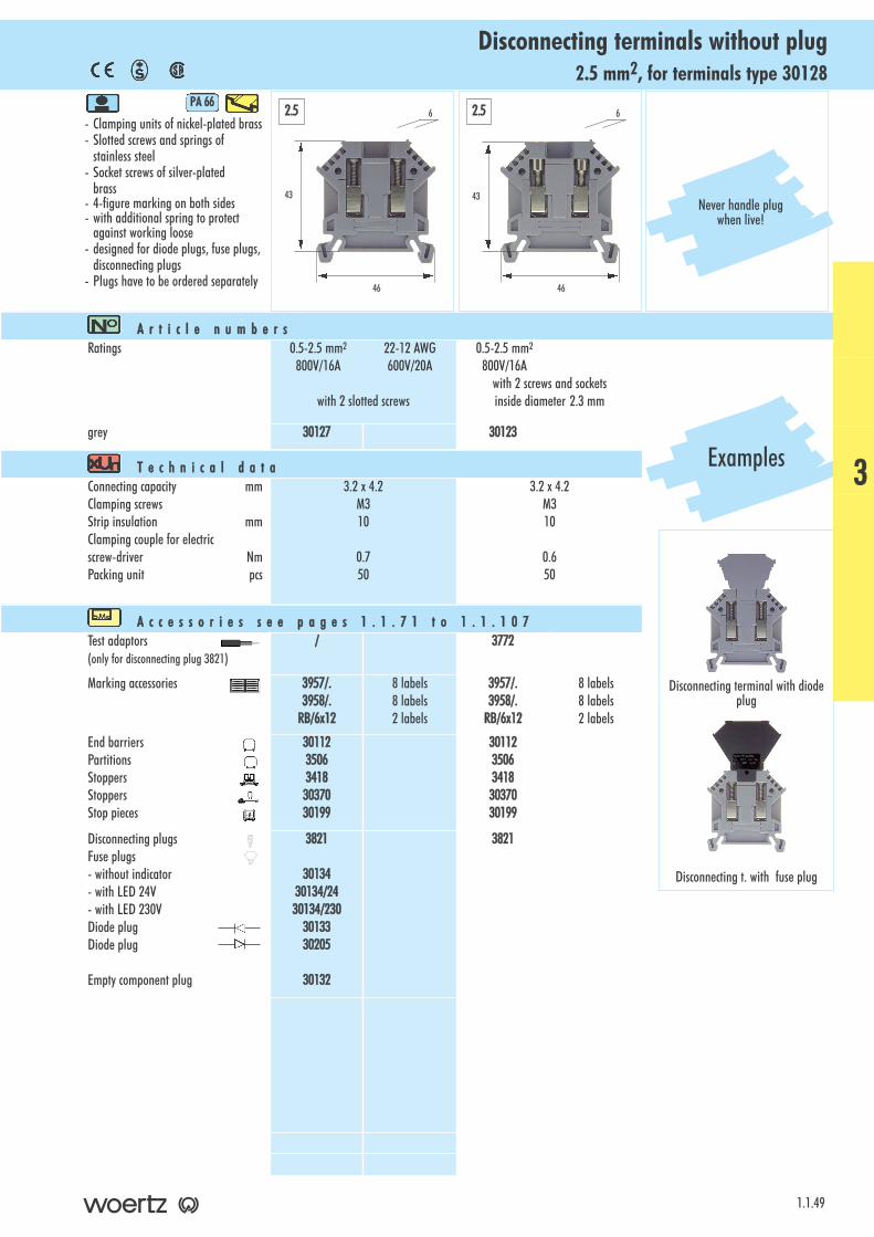
2.5 mm2, for terminals type 30128Disconnecting terminals without plug
- Clamping units of nickel-plated brass- Slotted screws and springs of
stainless steel- Socket screws of silver-plated
brass- 4-figure marking on both sides- with additional spring to protect
against working loose- designed for diode plugs, fuse plugs,
disconnecting plugs- Plugs have to be ordered separately
PA 666
1.1.49
A r t i c l e nn u m b e r sRatings 0.5-2.5 mm2 22-12 AWG
800V/16A 600V/20A
with 2 slotted screws
0.5-2.5 mm2
800V/16Awith 2 screws and socketsinside diameter 2.3 mm
grey 30127 30123
T e c h n i c a l dd a t aConnecting capacity mmClamping screwsStrip insulation mmClamping couple for electricscrew-driver NmPacking unit pcs
3.2 x 4.2M310
0.750
3.2 x 4.2M310
0.650
A c c e s s o r i e s ss e e pp a g e s 11 . 1 . 7 1 tt o 11 . 1 . 1 0 7Test adaptors(only for disconnecting plug 3821)
/ 3772
Marking accessories 3957/.3958/.
RB/6x12
8 labels8 labels2 labels
3957/.3958/.
RB/6x12
8 labels8 labels2 labels
End barriersPartitionsStoppersStoppersStop pieces
30112350634183037030199
30112350634183037030199
Disconnecting plugsFuse plugs - without indicator- with LED 24V- with LED 230VDiode plugDiode plug
Empty component plug
3821
3013430134/2430134/230
3013330205
30132
3821
43
46
6
43
46
62.5 2.5
Never handle plugwhen live!
Examples
Disconnecting terminal with diodeplug
Disconnecting t. with fuse plug
3
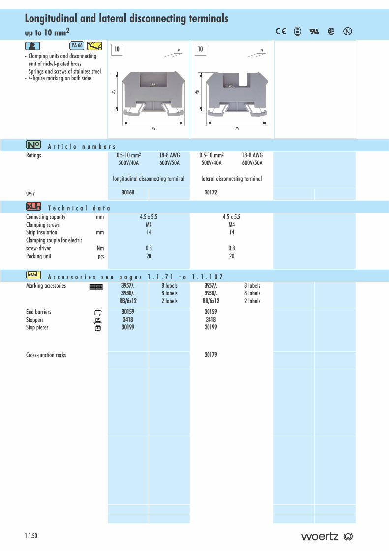
up to 10 mm2Longitudinal and lateral disconnecting terminals
1.1.50
- Clamping units and disconnectingunit of nickel-plated brass
- Springs and screws of stainless steel- 4-figure marking on both sides
PA 666
A r t i c l e nn u m b e r sRatings 0.5-10 mm2 18-8 AWG
500V/40A 600V/50A
longitudinal disconnecting terminal
0.5-10 mm2 18-8 AWG500V/40A 600V/50A
lateral disconnecting terminal
grey 30168 30172
T e c h n i c a l dd a t aConnecting capacity mmClamping screwsStrip insulation mmClamping couple for electricscrew-driver NmPacking unit pcs
4.5 x 5.5M414
0.820
4.5 x 5.5M414
0.820
A c c e s s o r i e s ss e e pp a g e s 11 . 1 . 7 1 tt o 11 . 1 . 1 0 7Marking accessories 3957/.
3958/.RB/6x12
8 labels8 labels2 labels
3957/.3958/.
RB/6x12
8 labels8 labels2 labels
End barriersStoppersStop pieces
30159341830199
30159341830199
Cross-junction racks 30179
49
75
910 10
49
75
9
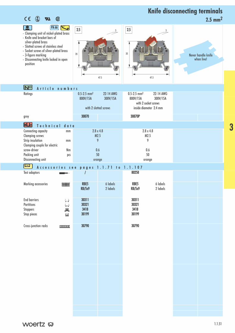
2.5 mm2Knife disconnecting terminals
- Clamping unit of nickel-plated brass- Knife and bracket bars of
silver-plated brass- Slotted screws of stainless steel- Socket screws of silver-plated brass- 3-figure marking- Disconnecting knife locked in open
position
PA 666
1.1.51
A r t i c l e nn u m b e r sRatings 0.5-2.5 mm2 22-14 AWG
800V/15A 300V/15A
with 2 slotted screws
0.5-2.5 mm2 22-14 AWG800V/15A 300V/15A
with 2 socket screwsinside diameter 2.4 mm
grey 30870 30870P
T e c h n i c a l dd a t aConnecting capacity mmClamping screwsStrip insulation mmClamping couple for electricscrew-driver NmPacking unit pcsDisconnecting unit
2.8 x 4.8M2.5
9
0.650
orange
2.8 x 4.8M2.5
9
0.650
orange
A c c e s s o r i e s ss e e pp a g e s 11 . 1 . 7 1 tt o 11 . 1 . 1 0 7Test adaptors / 80258
Marking accessories RBE5RB/5x9
6 labels2 labels
RBE5RB/5x9
6 labels2 labels
End barriersPartitionsStoppersStop pieces
3031130321341830199
3031130321341830199
Cross-junction racks 30790 30790
35
47.5
5
35
47.5
52.5 2.5
Never handle knifewhen live!
3
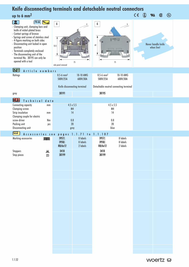
up to 6 mm2Knife disconnecting terminals and detachable neutral connectors
1.1.52
- Clamping unit, clamping bars and knife of nickel-plated brass
- Contact springs of bronze- Springs and screws of stainless steel- 4-figure marking on both sides- Disconnecting unit locked in open
position- Terminals completely enclosed- The disconnecting unit of the
terminal No. 30195 can only beopened with a tool
PA 666
A r t i c l e nn u m b e r sRatings 0.5-6 mm2 18-10 AWG
500V/25A 600V/30A
Knife disconnecting terminal
0.5-6 mm2 18-10 AWG500V/25A 600V/30A
Detachable neutral connecting terminal
grey 30191 30195
T e c h n i c a l dd a t aConnecting capacity mmClamping screwsStrip insulation mmClamping couple for electricscrew-driver NmPacking unit pcsDisconnecting unit
4.5 x 5.5M414
0.820
grey
4.5 x 5.5M414
0.820
blue
A c c e s s o r i e s ss e e pp a g e s 11 . 1 . 7 1 tt o 11 . 1 . 1 0 7Marking accessories 3957/.
3958/.RB/6x12
8 labels8 labels2 labels
3957/.3958/.
RB/6x12
8 labels8 labels2 labels
StoppersStop pieces
341830199
341830199
53.5
75
96 6
49
75
9
Never handle knifewhen live!
side panel removed
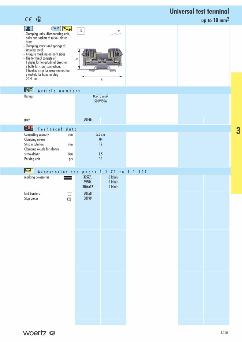
up to 10 mm2Universal test terminal
- Clamping units, disconnecting unit,bolts and sockets of nickel-plated brass
- Clamping screws and springs ofstainless steel
- 4-figure marking on both sides- The terminal consists of
1 slider for longitudinal direction, 2 bolts for cross-connection, 1 hooked strip for cross-connection, 2 sockets for banana plug ∅ 4 mm
PA 666
1.1.53
A r t i c l e nn u m b e r sRatings 0.5-10 mm2
500V/50A
grey 30146
T e c h n i c a l dd a t aConnecting capacity mmClamping screwsStrip insulation mmClamping couple for electricscrew-driver NmPacking unit pcs
5.5 x 6M412
1.510
A c c e s s o r i e s ss e e pp a g e s 11 . 1 . 7 1 tt o 11 . 1 . 1 0 7Marking accessories 3957/..
3958/.RB/6x12
8 labels8 labels2 labels
End barriersStop pieces
3015830199
47
91
1110
3

up to 10 mm2Fuse terminals with fuse-carrier
1.1.54
- Clamping unit of nickel-plated brass- Springs and screws of stainless steel- 4-figure marking on both sides- May be provided with a fuse up to
max. 6.3A either 5x20mm or 1/4”x11/4” (6.3x32mm)
- Available with LED 24V to indicatedamaged fuse
- Delivered without fuse
PA 666
A r t i c l e nn u m b e r sRatings 0.5-10 mm2 20-8 AWG
250V/6.3A 300V/6.3A
without indicator
0.5-10 mm2 20-8 AWG250V/6.3A 300V/6.3A
with LED 24 V for fuse 24V
grey 30176 30228
T e c h n i c a l dd a t aConnecting capacity mmClamping screwsStrip insulation mmClamping couple for electricscrew-driver NmPacking unit pcs
4.5 x 5.5M414
0.820
4.5 x 5.5M414
0.820
A c c e s s o r i e s ss e e pp a g e s 11 . 1 . 7 1 tt o 11 . 1 . 1 0 7Marking accessories 3957/.
3958/.RB/6x12
8 labels8 labels2 labels
3957/.3958/.
RB/6x12
8 labels8 labels2 labels
End barriersStoppersStop pieces
30159341830199
30159341830199
Separate fuse-carriermay be provided with a fuse up tomax. 6.3A either 5x20mm or1/4”x11/4” (6.3x32mm)
30180 30180
59
75
910 10
59
75
9
Never handlefuse-carrier when live!
Technicalinformation
In a single fuse terminal, a heavierload is possible than in a bloc of seve-ral fuse terminals strung together thatheat each other up. This source ofheat has to be taken into accountwhen planning.

up to 10 mm2Fuse terminals without indicator
- Screw cap of thermosetting plastic - Clamping units and bars of
nickel-plated brass- Screws and springs of stainless steel- 4-figure marking on both sides- Delivered without fuse
PA 666
1.1.55
A r t i c l e nn u m b e r sRatings 0.5-10 mm2 20-8 AWG
250V/6.3A 300V/10A
for fuse 5 x 20 mm
0.5-10 mm2 20-8 AWG250V/10A 300V/10A
for fuse 1/4” x 11/4” (6.3 x 32mm)
grey 30005 30008
T e c h n i c a l dd a t aConnecting capacity mmClamping screwsThread in connecting barStrip insulation mmClamping couple for electricscrew-driver NmPacking unit pcsMax. operating voltage of the fuse VRated current of the fuse A
5.8 x 7.7M4M313
1.510
250/3000.032-6.3/10
5.8 x 7.7M4M313
1.510
250/3000.032-10
A c c e s s o r i e s ss e e pp a g e s 11 . 1 . 7 1 tt o 11 . 1 . 1 0 7Test adaptors 80070
2737800702737
Marking accessories 3957/.3958/.
RB/6x12
8 labels8 labels2 labels
3957/.3958/.
RB/6x12
8 labels8 labels2 labels
End barriersStoppersStoppersStop pieces
3002534183037030199
3002534183037030199
59
68
13
59
68
1310 10
3
Technicalinformation
In a single fuse terminal, a heavierload is possible than in a bloc of seve-ral fuse terminals strung together thatheat each other up. This source ofheat has to be taken into accountwhen planning.
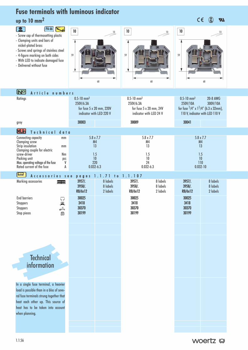
up to 10 mm2Fuse terminals with luminous indicator
1.1.56
- Screw cap of thermosetting plastic - Clamping units and bars of
nickel-plated brass- Screws and springs of stainless steel- 4-figure marking on both sides- With LED to indicate damaged fuse- Delivered without fuse
PA 666
A r t i c l e nn u m b e r sRatings 0.5-10 mm2
250V/6.3Afor fuse 5 x 20 mm, 220Vindicator with LED 220 V
0.5-10 mm2
250V/6.3Afor fuse 5 x 20 mm, 24Vindicator with LED 24 V
0.5-10 mm2 20-8 AWG250V/10A 300V/10A
for fuse 1/4” x 11/4” (6.3 x 32mm),110 V, indicator with LED 110 V
grey 30003 30009 30041
T e c h n i c a l dd a t aConnecting capacity mmClamping screwStrip insulation mmClamping couple for electricscrew-driver NmPacking unit pcsMax. operating voltage of the fuse VRated current of the fuse A
5.8 x 7.7M413
1.510220
0.032-6.3
5.8 x 7.7M413
1.51024
0.032-6.3
5.8 x 7.7M413
1.510110
0.032-10
A c c e s s o r i e s ss e e pp a g e s 11 . 1 . 7 1 tt o 11 . 1 . 1 0 7Marking accessories 3957/.
3958/.RB/6x12
8 labels8 labels2 labels
3957/.3958/.
RB/6x12
8 labels8 labels2 labels
3957/.3958/.
RB/6x12
8 labels8 labels2 labels
End barriersStoppersStoppersStop pieces
3002534183037030199
3002534183037030199
3002534183037030199
59
68
1310 10 10
59
68
13
59
68
13
Technicalinformation
In a single fuse terminal, a heavierload is possible than in a bloc of seve-ral fuse terminals strung together thatheat each other up. This source ofheat has to be taken into accountwhen planning.
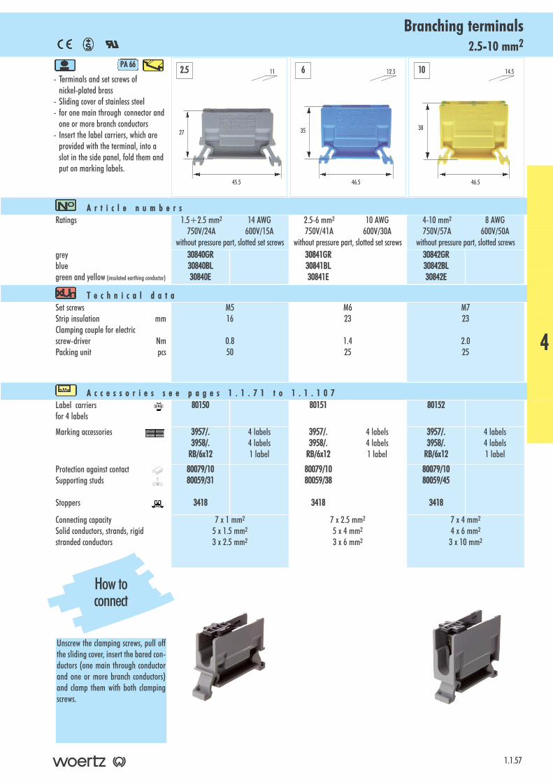
2.5-10 mm2Branching terminals
- Terminals and set screws of nickel-plated brass
- Sliding cover of stainless steel- for one main through connector and
one or more branch conductors- Insert the label carriers, which are
provided with the terminal, into a slot in the side panel, fold them andput on marking labels.
PA 666
1.1.57
A r t i c l e nn u m b e r sRatings 1.5+2.5 mm2 14 AWG
750V/24A 600V/15Awithout pressure part, slotted set screws
2.5-6 mm2 10 AWG750V/41A 600V/30A
without pressure part, slotted set screws
4-10 mm2 8 AWG750V/57A 600V/50A
without pressure part, slotted screwsgreybluegreen and yellow (insulated earthing conductor)
30840GR30840BL30840E
30841GR30841BL30841E
30842GR30842BL30842E
T e c h n i c a l dd a t aSet screwsStrip insulation mmClamping couple for electricscrew-driver NmPacking unit pcs
M516
0.850
M623
1.425
M723
2.025
A c c e s s o r i e s ss e e pp a g e s 11 . 1 . 7 1 tt o 11 . 1 . 1 0 7Label carriersfor 4 labels
80150 80151 80152
Marking accessories 3957/.3958/.
RB/6x12
4 labels4 labels1 label
3957/.3958/.
RB/6x12
4 labels4 labels1 label
3957/.3958/.
RB/6x12
4 labels4 labels1 label
Protection against contactSupporting studs
Stoppers
80079/1080059/31
3418
80079/1080059/38
3418
80079/1080059/45
3418
Connecting capacity Solid conductors, strands, rigidstranded conductors
7 x 1 mm2
5 x 1.5 mm2
3 x 2.5 mm2
7 x 2.5 mm2
5 x 4 mm2
3 x 6 mm2
7 x 4 mm2
4 x 6 mm2
3 x 10 mm2
27
45.5
11
35
46.5
12.5
38
46.5
14.52.5 6 10
How toconnect
Unscrew the clamping screws, pull offthe sliding cover, insert the bared con-ductors (one main through conductorand one or more branch conductors)and clamp them with both clampingscrews.
4
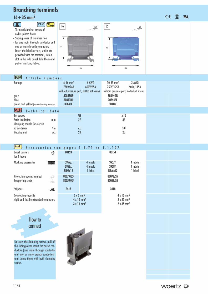
16+35 mm2Branching terminals
1.1.58
- Terminals and set screws of nickel-plated brass
- Sliding cover of stainless steel- for one main through conductor and
one or more branch conductors- Insert the label carriers, which are
provided with the terminal, into a slot in the side panel, fold them andput on marking labels.
PA 666
A r t i c l e nn u m b e r sRatings 6-16 mm2 6 AWG
750V/76A 600V/65Awithout pressure part, slotted set screws
10-35 mm2 2 AWG750V/125A 600V/115A
without pressure part, slotted set screwsgreybluegreen and yellow (insulated earthing conductor)
30843GR30843BL30843E
30844GR30844BL30844E
T e c h n i c a l dd a t aSet screwsStrip insulation mmClamping couple for electricscrew-driver NmPacking unit pcs
M827
2.320
M1235
3.820
A c c e s s o r i e s ss e e pp a g e s 11 . 1 . 7 1 tt o 11 . 1 . 1 0 7Label carriersfor 4 labels
80153 80154
Marking accessories 3957/.3958/.
RB/6x12
4 labels4 labels1 label
3957/.3958/.
RB/6x12
4 labels4 labels1 label
Protection against contactSupporting studs
Stoppers
80079/3580059/45
3418
80079/3580059/55
3418
Connecting capacity rigid and flexible stranded conductors
6 x 6 mm2
4 x 10 mm2
3 x 16 mm2
4 x 16 mm2
2 x 25 mm2
2 x 35 mm2
44
50
16.516 35
47
54
21
How toconnect
Unscrew the clamping screws, pull offthe sliding cover, insert the bared con-ductors (one main through conductorand one or more branch conductors)and clamp them with both clampingscrews.
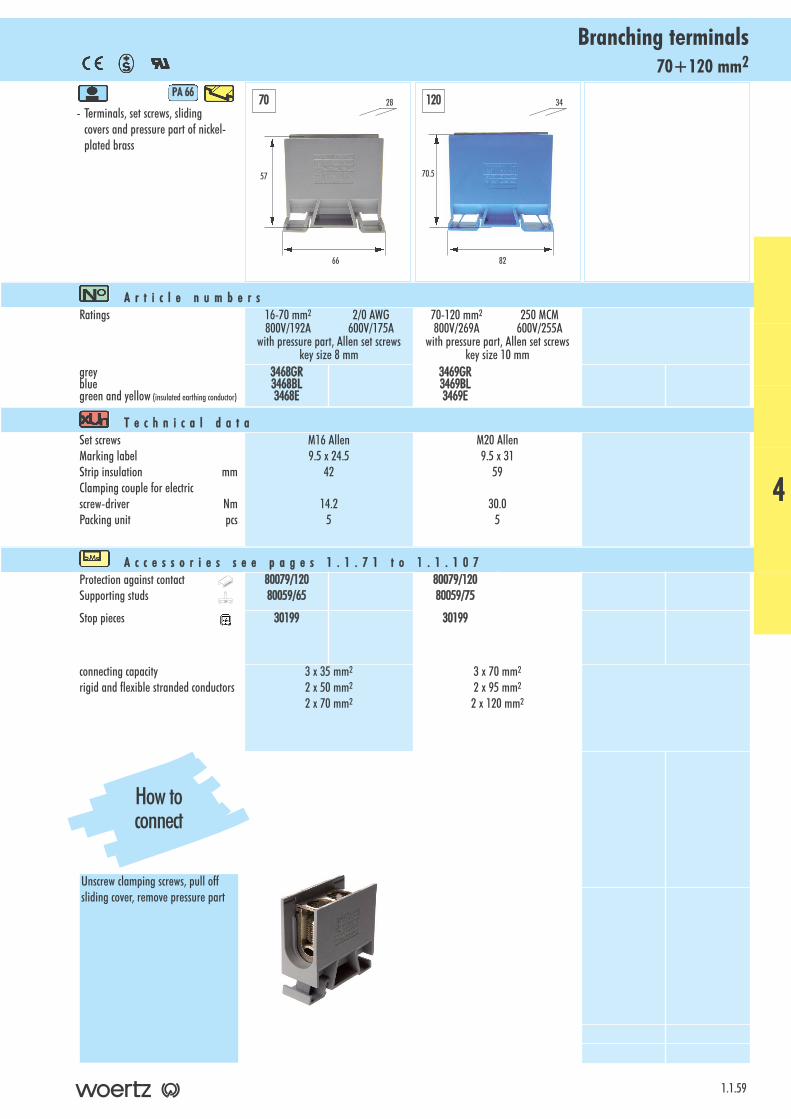
70+120 mm2Branching terminals
- Terminals, set screws, slidingcovers and pressure part of nickel-plated brass
PA 666
1.1.59
A r t i c l e nn u m b e r sRatings 16-70 mm2 2/0 AWG
800V/192A 600V/175Awith pressure part, Allen set screws
key size 8 mm
70-120 mm2 250 MCM800V/269A 600V/255A
with pressure part, Allen set screwskey size 10 mm
greybluegreen and yellow (insulated earthing conductor)
3468GR3468BL3468E
3469GR3469BL3469E
T e c h n i c a l dd a t aSet screwsMarking labelStrip insulation mmClamping couple for electricscrew-driver NmPacking unit pcs
M16 Allen9.5 x 24.5
42
14.25
M20 Allen9.5 x 31
59
30.05
A c c e s s o r i e s ss e e pp a g e s 11 . 1 . 7 1 tt o 11 . 1 . 1 0 7Protection against contactSupporting studs
80079/12080059/65
80079/12080059/75
Stop pieces 30199 30199
connecting capacity rigid and flexible stranded conductors
3 x 35 mm2
2 x 50 mm2
2 x 70 mm2
3 x 70 mm2
2 x 95 mm2
2 x 120 mm2
57
66
28
70.5
82
3470 120
How toconnect
Unscrew clamping screws, pull offsliding cover, remove pressure part
4
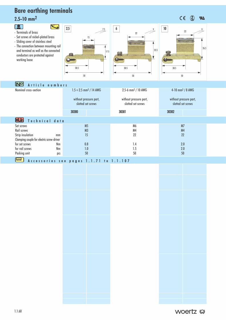
2.5-10 mm2Bare earthing terminals
1.1.60
- Terminals of brass- Set screws of nickel-plated brass- Sliding cover of stainless steel- The connection between mounting rail
and terminal as well as the connected conductors are protected against working loose
A r t i c l e nn u m b e r sNominal cross-section 1.5+2.5 mm2 / 14 AWG
without pressure part,slotted set screws
2.5-6 mm2 / 10 AWG
without pressure part,slotted set screws
4-10 mm2 / 8 AWG
without pressure part,slotted set screws
30380 30381 30382
T e c h n i c a l dd a t aSet screwsRail screwsStrip insulation mmClamping couple for electric screw-driverfor set screws Nmfor rail screws NmPacking unit pcs
M5M315
0.81.050
M6M422
1.41.550
M7M422
2.02.050
A c c e s s o r i e s ss e e pp a g e s 11 . 1 . 7 1 tt o 11 . 1 . 1 0 7
17.5
50
7.52.5 6 10
30.5
15
23.5
50
9
30.5
22
26.5
50
11
30.5
22

16+35 mm2Bare earthing terminals
- Terminals of brass- Set screws of nickel-plated brass- Sliding cover of stainless steel- The connection between mounting rail
and terminal as well as the connected conductors are protected against working loose
1.1.61
A r t i c l e nn u m b e r sNominal cross-section 6-16 mm2 / 6 AWG
without pressure part,slotted set screws
10-35 mm2 / 2 AWG
without pressure part,slotted set screws
30383 30384
T e c h n i c a l dd a t aSet screwsRail screwsStrip insulation mmClamping couple for electric screw-driverfor set screws Nmfor rail screws NmPacking unit pcs
M8M426
2.32.550
M12M434
3.83.050
A c c e s s o r i e s ss e e pp a g e s 11 . 1 . 7 1 tt o 11 . 1 . 1 0 7
Mounting rail according to EN 60715 TH 35 7.3x1 No. 3401corresponds to resistance to short-circuits of a conductor 16 mm2
Mounting rail according to EN 60715 TH 35 15x2.5 No. 3490corresponds to resistance to short-circuits of a conductor 50 mm2
Mounting rail according to EN 60715 TH 35 15x2.3 Cu No. 80290corresponds to resistance to short-cirucuits of a conductor 150 mm2
16 35
31.5
50
13
30.5
26
33.5
50
17
30.5
34
4
Technicalinformation

70+120 mm2Bare earthing terminals
1.1.62
- Terminal and sliding cover of brass- Pressure part and set screws of
nickel-plated brass- The connection between mounting rail
and terminal as well as the connected conductors are protected against working loose
A r t i c l e nn u m b e r sNominal cross-section 16-70 mm2
with pressure part, Allen set screwskey size 8 mm
70-120 mm2
with pressure part, Allen set screwskey size 10 mm
30181 30182
T e c h n i c a l dd a t aSet screwsScrew for pressure partStrip insulation mmClamping couple for electric screw-driverfor set screws Nmfor screws for pressure part Nm Packing unit pcs
M16 AllenM442
26.02.510
M20 AllenM458
30.02.510
A c c e s s o r i e s ss e e pp a g e s 11 . 1 . 7 1 tt o 11 . 1 . 1 0 7
Mounting rail according to EN 60715 TH 35 7.3x1 No 3401corresponds to the resistance to short-circuits of a conductor 16 mm2
Mounting rail according to EN 60715 TH 35 15x2.5 No. 3490corresponds to the resistance to short-circuits of a conductor 50 mm2
Mounting rail according to EN 60715 TH 35 15x2.3 Cu No. 80290corresponds to the resistance to short-circuits of a conductor 150 mm2
51
48
2270 120
70
58
29
Technicalinformation
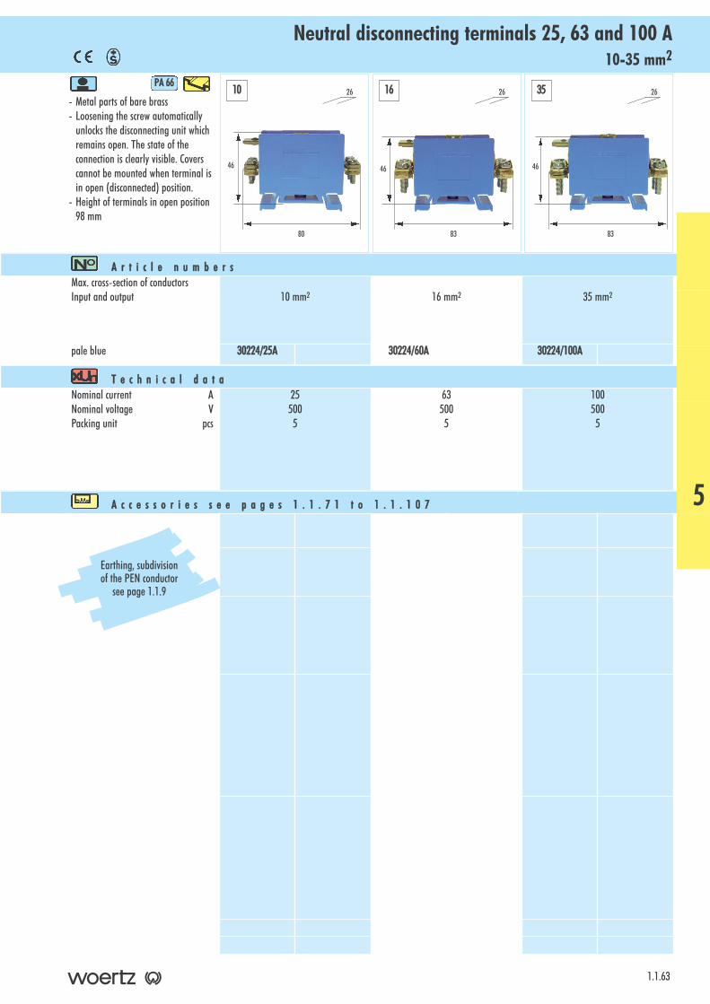
10-35 mm2Neutral disconnecting terminals 25, 63 and 100 A
- Metal parts of bare brass- Loosening the screw automatically
unlocks the disconnecting unit whichremains open. The state of theconnection is clearly visible. Coverscannot be mounted when terminal isin open (disconnected) position.
- Height of terminals in open position 98 mm
PA 666
1.1.63
A r t i c l e nn u m b e r sMax. cross-section of conductors Input and output 10 mm2 16 mm2 35 mm2
pale blue 30224/25A 30224/60A 30224/100A
T e c h n i c a l dd a t aNominal current ANominal voltage VPacking unit pcs
255005
635005
1005005
A c c e s s o r i e s ss e e pp a g e s 11 . 1 . 7 1 tt o 11 . 1 . 1 0 7
46
80
26
46
83
26
46
83
2610 16 35
5
Earthing, subdivision of the PEN conductor
see page 1.1.9
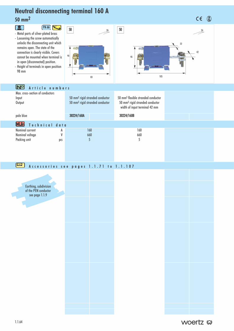
50 mm2Neutral disconnecting terminal 160 A
1.1.64
- Metal parts of silver-plated brass- Loosening the screw automatically
unlocks the disconnecting unit whichremains open. The state of theconnection is clearly visible. Coverscannot be mounted when terminal isin open (disconnected) position.
- Height of terminals in open position98 mm
PA 666
A r t i c l e nn u m b e r sMax. cross-section of conductors InputOutput
50 mm2 rigid stranded conductor50 mm2 rigid stranded conductor
50 mm2 flexible stranded conductor50 mm2 rigid stranded conductorwidth of input terminal 42 mm
pale blue 30224/160A 30224/160B
T e c h n i c a l dd a t aNominal current ANominal voltage VPacking unit pcs
1606605
1606605
A c c e s s o r i e s ss e e pp a g e s 11 . 1 . 7 1 tt o 11 . 1 . 1 0 7
46
83
2650 50
46
105
26
22
Earthing, subdivision of the PEN conductor
see page 1.1.9
42
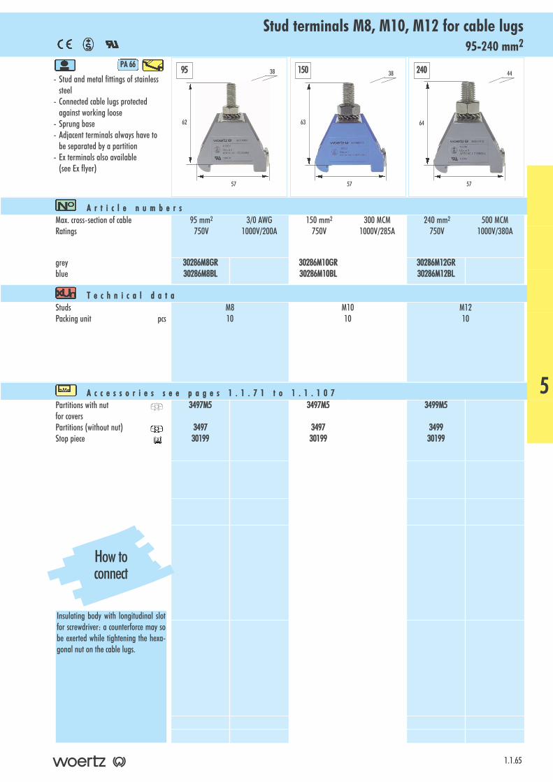
95-240 mm2Stud terminals M8, M10, M12 for cable lugs
- Stud and metal fittings of stainlesssteel
- Connected cable lugs protectedagainst working loose
- Sprung base- Adjacent terminals always have to
be separated by a partition- Ex terminals also available
(see Ex flyer)
PA 666
1.1.65
A r t i c l e nn u m b e r sMax. cross-section of cableRatings
95 mm2 3/0 AWG750V 1000V/200A
150 mm2 300 MCM750V 1000V/285A
240 mm2 500 MCM750V 1000V/380A
greyblue
30286M8GR30286M8BL
30286M10GR30286M10BL
30286M12GR30286M12BL
T e c h n i c a l dd a t aStudsPacking unit pcs
M810
M1010
M1210
A c c e s s o r i e s ss e e pp a g e s 11 . 1 . 7 1 tt o 11 . 1 . 1 0 7Partitions with nutfor coversPartitions (without nut)Stop piece
3497M5
349730199
3497M5
349730199
3499M5
349930199
62
57
38
63
57
38
64
57
4495 150 240
How toconnect
Insulating body with longitudinal slotfor screwdriver: a counterforce may sobe exerted while tightening the hexa-gonal nut on the cable lugs.
5
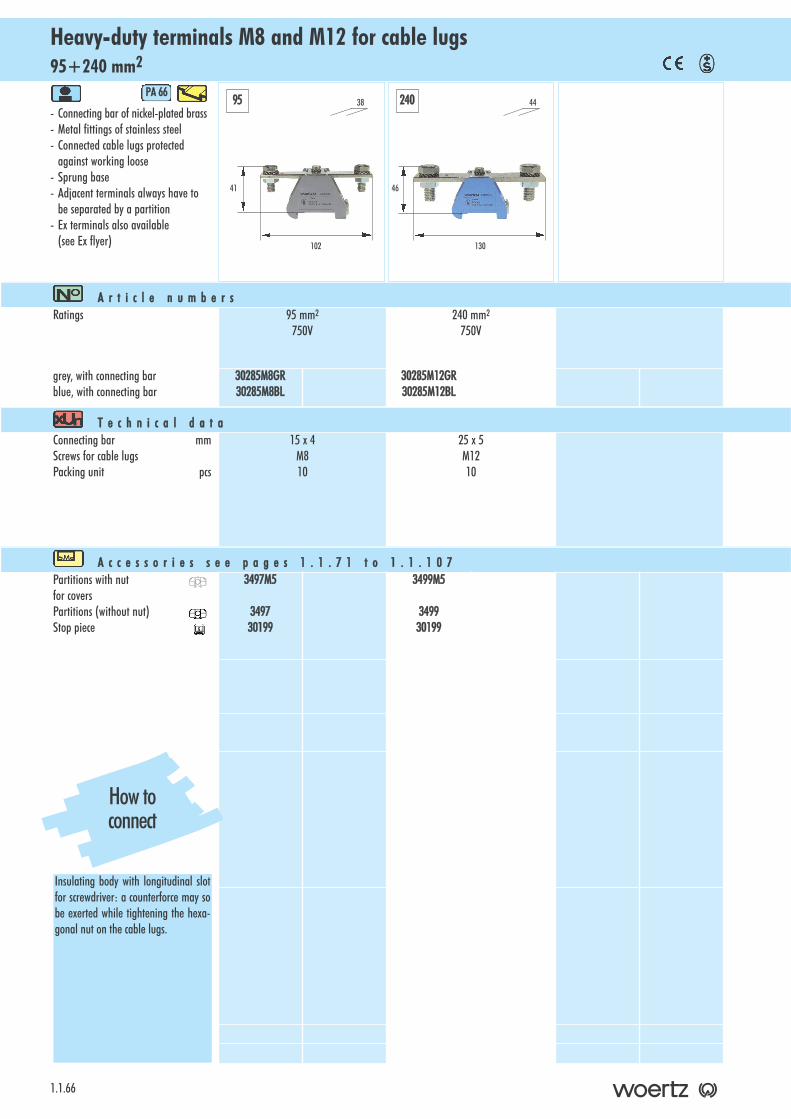
95+240 mm2Heavy-duty terminals M8 and M12 for cable lugs
1.1.66
- Connecting bar of nickel-plated brass- Metal fittings of stainless steel- Connected cable lugs protected
against working loose- Sprung base- Adjacent terminals always have to
be separated by a partition- Ex terminals also available
(see Ex flyer)
PA 666
A r t i c l e nn u m b e r sRatings 95 mm2
750V240 mm2
750V
grey, with connecting barblue, with connecting bar
30285M8GR30285M8BL
30285M12GR30285M12BL
T e c h n i c a l dd a t aConnecting bar mmScrews for cable lugsPacking unit pcs
15 x 4M810
25 x 5M1210
A c c e s s o r i e s ss e e pp a g e s 11 . 1 . 7 1 tt o 11 . 1 . 1 0 7Partitions with nutfor coversPartitions (without nut)Stop piece
3497M5
349730199
3499M5
349930199
41
102
3895 240
46
130
44
How toconnect
Insulating body with longitudinal slotfor screwdriver: a counterforce may sobe exerted while tightening the hexa-gonal nut on the cable lugs.
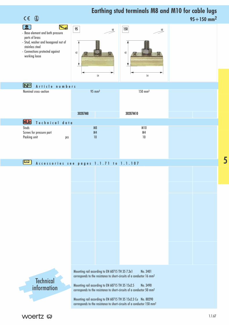
95+150 mm2Earthing stud terminals M8 and M10 for cable lugs
- Base element and both pressureparts of brass
- Stud, washer and hexagonal nut of stainless steel
- Connections protected against working loose
1.1.67
A r t i c l e nn u m b e r sNominal cross-section 95 mm2 150 mm2
30287M8 30287M10
T e c h n i c a l dd a t aStudsScrews for pressure partPacking unit pcs
M8M410
M10M410
A c c e s s o r i e s ss e e pp a g e s 11 . 1 . 7 1 tt o 11 . 1 . 1 0 7
Mounting rail according to EN 60715 TH 35 7.3x1 No. 3401corresponds to the resistance to short-circuits of a conductor 16 mm2
Mounting rail according to EN 60715 TH 35 15x2.5 No. 3490corresponds to the resistance to short-circuits of a conductor 50 mm2
Mounting rail according to EN 60715 TH 35 15x2.3 Cu No. 80290corresponds to the resistance to short-circuits of a conductor 150 mm2
42
54
48
42
54
4895 150
5
Technicalinformation
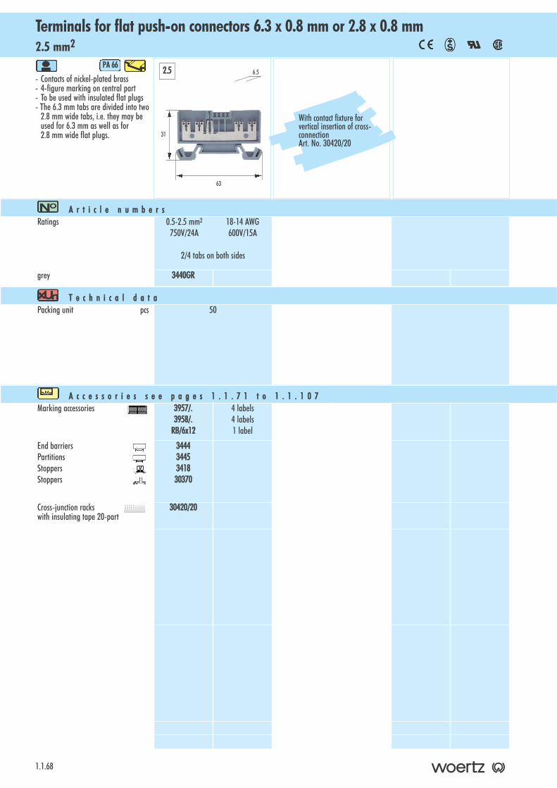
2.5 mm2Terminals for flat push-on connectors 6.3 x 0.8 mm or 2.8 x 0.8 mm
1.1.68
- Contacts of nickel-plated brass- 4-figure marking on central part- To be used with insulated flat plugs- The 6.3 mm tabs are divided into two
2.8 mm wide tabs, i.e. they may beused for 6.3 mm as well as for2.8 mm wide flat plugs.
PA 666
A r t i c l e nn u m b e r sRatings 0.5-2.5 mm2 18-14 AWG
750V/24A 600V/15A
2/4 tabs on both sides
grey 3440GR
T e c h n i c a l dd a t aPacking unit pcs 50
A c c e s s o r i e s ss e e pp a g e s 11 . 1 . 7 1 tt o 11 . 1 . 1 0 7Marking accessories 3957/.
3958/.RB/6x12
4 labels4 labels1 label
End barriersPartitionsStoppersStoppers
34443445341830370
Cross-junction racks with insulating tape 20-part
30420/20
31
63
6.52.5
With contact fixture forvertical insertion of cross-connection Art. No. 30420/20
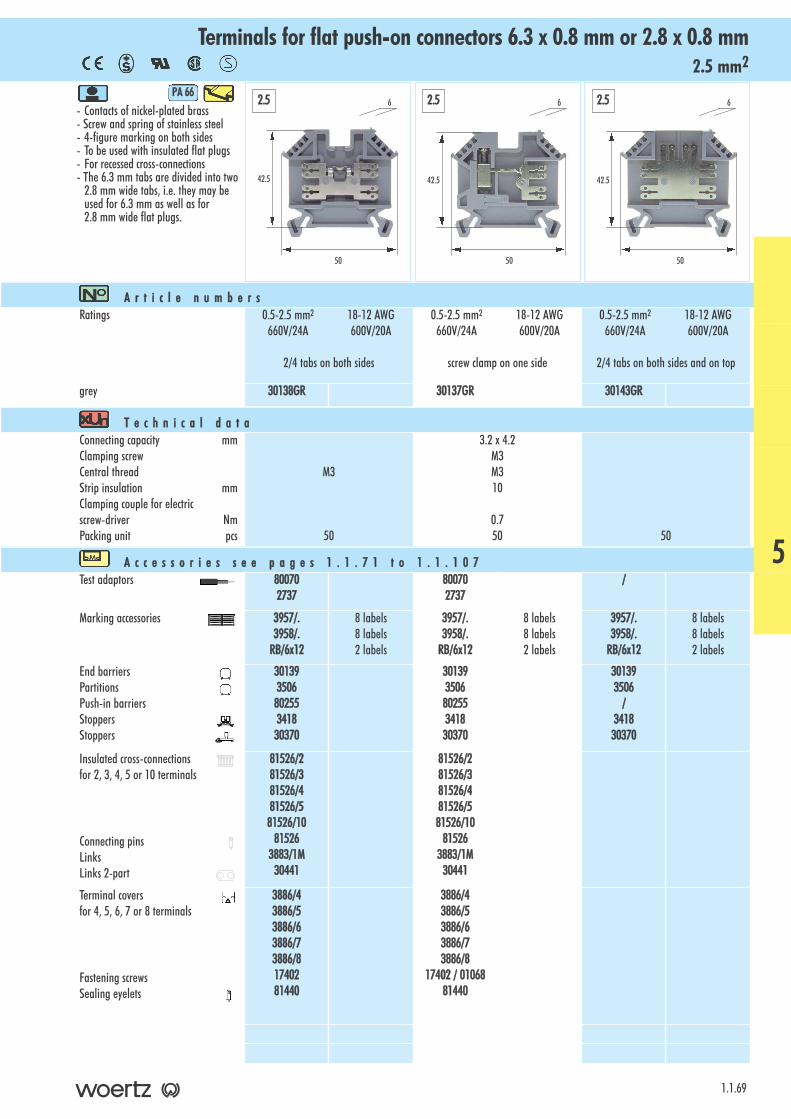
2.5 mm2Terminals for flat push-on connectors 6.3 x 0.8 mm or 2.8 x 0.8 mm
- Contacts of nickel-plated brass- Screw and spring of stainless steel - 4-figure marking on both sides- To be used with insulated flat plugs- For recessed cross-connections- The 6.3 mm tabs are divided into two
2.8 mm wide tabs, i.e. they may beused for 6.3 mm as well as for2.8 mm wide flat plugs.
PA 666
1.1.69
A r t i c l e nn u m b e r sRatings 0.5-2.5 mm2 18-12 AWG
660V/24A 600V/20A
2/4 tabs on both sides
0.5-2.5 mm2 18-12 AWG660V/24A 600V/20A
screw clamp on one side
0.5-2.5 mm2 18-12 AWG660V/24A 600V/20A
2/4 tabs on both sides and on top
grey 30138GR 30137GR 30143GR
T e c h n i c a l dd a t aConnecting capacity mmClamping screwCentral threadStrip insulation mmClamping couple for electricscrew-driver NmPacking unit pcs
M3
50
3.2 x 4.2M3M310
0.750 50
A c c e s s o r i e s ss e e pp a g e s 11 . 1 . 7 1 tt o 11 . 1 . 1 0 7Test adaptors 80070
2737 800702737
/
Marking accessories 3957/.3958/.
RB/6x12
8 labels8 labels2 labels
3957/.3958/.
RB/6x12
8 labels8 labels2 labels
3957/.3958/.
RB/6x12
8 labels8 labels2 labels
End barriersPartitionsPush-in barriersStoppersStoppers
30139350680255341830370
30139350680255341830370
301393506
/341830370
Insulated cross-connectionsfor 2, 3, 4, 5 or 10 terminals
Connecting pinsLinks Links 2-part
81526/281526/381526/481526/581526/10
815263883/1M
30441
81526/281526/381526/481526/581526/10
815263883/1M
30441
Terminal covers for 4, 5, 6, 7 or 8 terminals
Fastening screws Sealing eyelets
3886/43886/53886/63886/73886/81740281440
3886/43886/53886/63886/73886/8
17402 // 00106881440
42.5
50
6
42.5
50
6
42.5
50
62.5 2.5 2.5
5
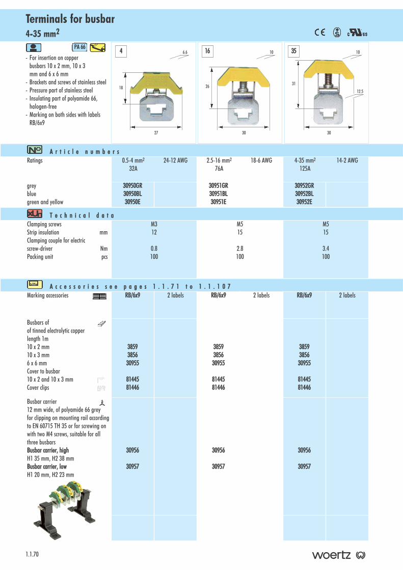
4-35 mm2Terminals for busbar
1.1.70
- For insertion on copperbusbars 10 x 2 mm, 10 x 3 mm and 6 x 6 mm
- Brackets and screws of stainless steel- Pressure part of stainless steel- Insulating part of polyamide 66,
halogen-free- Marking on both sides with labels
RB/6x9
PA 666
A r t i c l e nn u m b e r sRatings 0.5-4 mm2 24-12 AWG
32A2.5-16 mm2 18-6 AWG
76A4-35 mm2 14-2 AWG
125A
greybluegreen and yellow
30950GR30950BL30950E
30951GR30951BL30951E
30952GR30952BL30952E
T e c h n i c a l dd a t aClamping screwsStrip insulation mmClamping couple for electricscrew-driver NmPacking unit pcs
M312
0.8100
M515
2.8100
M515
3.4100
A c c e s s o r i e s ss e e pp a g e s 11 . 1 . 7 1 tt o 11 . 1 . 1 0 7Marking accessories RB/6x9 2 labels RB/6x9 2 labels RB/6x9 2 labels
Busbars ofof tinned electrolytic copperlength 1m10 x 2 mm10 x 3 mm6 x 6 mmCover to busbar 10 x 2 and 10 x 3 mmCover clips
3859385630955
8144581446
3859385630955
8144581446
3859385630955
8144581446
Busbar carrier12 mm wide, of polyamide 66 greyfor clipping on mounting rail accordingto EN 60715 TH 35 or for screwing onwith two M4 screws, suitable for allthree busbarsBusbar ccarrier, hhighH1 35 mm, H2 38 mmBusbar ccarrier, llowH1 20 mm, H2 23 mm
30956
30957
30956
30957
30956
30957
18
27
6.64 35
31
30
1016
26
30
10
12.5

1.1.71
IndexAccessories for terminals for mounting rails 35mm according to EN 60715 TH 35
A c c e s s o r i e s p a g e s 11 . 1 . 7 1 tt o 11 . 1 . 1 0 7E n d b a r r i e r s . . . . . . . . . . . . . . . . . . . . . . . . . 1 . 1 . 7 2 - 1 . 1 . 7 4P a r t i t i o n s . . . . . . . . . . . . . . . . . . . . . . . . . . . 1 . 1 . 7 5 - 1 . 1 . 7 7P u s h - i n b a r r i e r s . . . . . . . . . . . . . . . . . . . . . . . . . . . 1 . 1 . 7 7S t o p p e r s a n d s t o p p i e c e s . . . . . . . . . . . . . . . . . . . . . . 1 . 1 . 7 8I n s u l a t e d c r o s s - c o n n e c t i o n s a n d a c c e s s o r i e s . . . . . . 1 . 1 . 7 9 - 1 . 1 . 8 4C r o s s - j u n c t i o n r a c k s . . . . . . . . . . . . . . . . . . . . 1 . 1 . 8 5 - 1 . 1 . 8 6T e r m i n a l c o v e r s a n d a c c e s s o r i e s . . . . . . . . . . . . . 1 . 1 . 8 7 - 1 . 1 . 9 1P r o t e c t i o n a g a i n s t a c c i d e n t a l c o n t a c t . . . . . . . . . . . . . . 1 . 1 . 9 2C o v e r s f o r s i n g l e t e r m i n a l s . . . . . . . . . . . . . . . . . . . . 1 . 1 . 9 3C o v e r s t o c r o s s - c o n n e c t o r s . . . . . . . . . . . . . . . . . . . . . 1 . 1 . 9 4D i s c o n n e c t i n g p l u g s a n d c o m p o n e n t p l u g s . . . . . . . . . . . . 1 . 1 . 9 5D i o d e p l u g s a n d f u s e p l u g s . . . . . . . . . . . . . . . . . . . . . 1 . 1 . 9 6B u s b a r s a n d a c c e s s o r i e s . . . . . . . . . . . . . . . . . . . . . . . 1 . 1 . 9 7T e s t p l u g s . . . . . . . . . . . . . . . . . . . . . . . . . . . 1 . 1 . 9 8 - 1 . 1 . 9 9M a r k i n g a c c e s s o r i e s . . . . . . . . . . . . . . . . . . . 1 . 1 . 1 0 0 - 1 . 1 . 1 0 4R a i l s a n d a c c e s s o r i e s . . . . . . . . . . . . . . . . . . 1 . 1 . 1 0 5 - 1 . 1 . 1 0 7

Return terminal 2.5mm2 Art. No. 30810of polyamide 66, greyPacking unit: 100 pcsW=1.5mm, L=42mm, H=56mm
3300881111
End barriers
1.1.72
E n d bb a r r i e r s tt o tt e r m i n a l ss e r i e s CC o m p a c t
for tterminalsTechnical ddataIllustrationArticle nnumber
H
L
Two-step terminals 6mm2 series 3410of polyamide 66, greyPacking unit: 100 pcsW=2mm, L=74mm, H=64mm
3411
Two-step terminals 2.5mm2 series 30860Two-step terminals 4mm2 series 3430
of polyamide 66, greyPacking unit: 100 pcsW=2mm, L=62mm, H=49mm
3431
Basic terminals 2.5mm2 series 30150Basic terminals 4mm2 series 3450Thermocouple terminals 2.5mm2 series 30880Disconnecting terminals 2.5mm2 series 30800
of polyamide 66, greyPacking unit: 100 pcsW=2mm, L=37mm, H=35mm
3460
Basic terminals 6-16mm2 series 3452/6, 3452/10,3452/16
of polyamide 66, greyPacking unit: 100 pcsW=2mm, L=45mm, H=41mm
3464
Three-step terminals for proximity switches 2.5mm2
Art. No. 30400of polyamide 66, greyPacking unit: 100 pcsW=2mm, L=65mm, H=44mm
30406
Three-step terminals for proximity switches 2.5mm2
Art. No. 30403of polyamide 66, greyPacking unit: 100 pcsW=2mm, L=87mm, H=44mm
30407
Three-step installation terminals 4mm2
Art. No. 30431/1, Art. No. 30431/2, Art. No. 30432of polyamide 66, greyPacking unit: 100 pcsW=2mm, L=89mm, H=50mm
3300443388
Three-step installation terminals 4mm2 Art. No. 30430of polyamide 66, bluePacking unit: 100 pcsW=2mm, L=89mm, H=50mmwith rail holder
3300443399
W
End barrier
Push-in barrier
Stopper
Partition

End barriers
1.1.73
E n d bb a r r i e r s tt o tt e r m i n a l ss e r i e s CC o m p a c t
for tterminalsTechnical ddataIllustrationArticle nnumber
Two-step terminals with disconnecting function Art. No.30890, Art. No. 30891
of polyamide 66, greyPacking unit: 100 pcsW=1.5mm, L=73.5mm, H=59mm
3300889922
Y-terminals 2.5+4mm2 series 30903, series 30904
of polyamide 66, greyPacking unit: 100 pcsW=1.5mm, L=45mm, H=41.5mm
3300991133
Fuse terminals 4mm2 series 30935of polyamide 66, blackPacking unit: 100 pcsW=2.5mm, L=71mm, H=46mm
3300994455
X-terminal 2.5mm2 series 30973of polyamide 66, greyPacking unit: 100 pcsW=1.5mm, L=54mm, H=41.5mm
3300998833
Detachable neutral conductor / neutral disconnectingterminal 4+6mm2 Art. No. 3472BL, 3477BL, 30197,30200
of polyamide 66, pale bluePacking unit: 100 pcsW=4.5mm, L=67mm, H1=52mm, H2=33mmwith busbar holder
3474BL
Detachable neutral conductor / neutral disconnectingterminal 16mm2 Art. No. 3473BL
of polyamide 66, pale bluePacking unit: 100 pcsW=4.5mm, L=70mm, H1=52mm, H2=33mmwith busbar holder
3475BL
Terminals for stringent demands 4+6mm2
Series 3424, series 3425of polyamide 66, greyPacking unit: 100 pcsW=2mm, L=49mm, H=45mm
3516
Terminals for stringent demands 10mm2
Series 3426of polyamide 66, greyPacking unit: 100 pcsW=2mm, L=52mm, H=51mm
3517
E n d bb a r r i e r s tt o tt e r m i n a l ss e r i e s CC o m f o r t
H2H1
H2H1
6
Terminals for stringent demands 35mm2
Series 3428of polyamide 66, greyPacking unit: 100 pcsW=2mm, L=60mm, H=71mm
3519
Terminals for stringent demands 16mm2
Series 3427of polyamide 66, greyPacking unit: 100 pcsW=2mm, L=55mm, H=55mm
3518
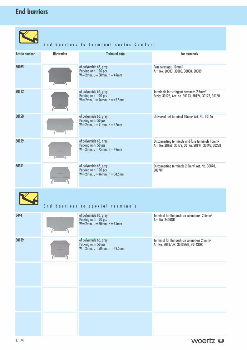
End barriers
1.1.74
E n d bb a r r i e r s tt o tt e r m i n a l ss e r i e s CC o m f o r t
for tterminalsTechnical ddataIllustrationArticle nnumber
Fuse terminals 10mm2
Art. No. 30003, 30005, 30008, 30009of polyamide 66, greyPacking unit: 100 pcsW=2mm, L=68mm, H=49mm
30025
Terminals for stringent demands 2.5mm2
Series 30128, Art. No. 30123, 30124, 30127, 30130of polyamide 66, greyPacking unit: 100 pcsW=2mm, L=46mm, H=42.5mm
30112
Universal test terminal 10mm2 Art. No. 30146of polyamide 66, greyPacking unit: 50 pcsW=2mm, L=91mm, H=47mm
30158
Disconnecting terminals and fuse terminals 10mm2
Art. No. 30168, 30172, 30176, 30191, 30195, 30228of polyamide 66, greyPacking unit: 50 pcsW=2mm, L=75mm, H=49mm
30159
Disconnecting terminals 2.5mm2 Art. No. 30870,30870P
of polyamide 66, greyPacking unit: 100 pcsW=2mm, L=46mm, H=34.5mm
30311
Terminal for flat push-on connectors 2.5mm2
Art. No. 3440GRof polyamide 66, greyPacking unit: 100 pcsW=2mm, L=60mm, H=31mm
3444
Terminal for flat push-on connectors 2.5mm2
Art.No. 30137GR, 30138GR, 30143GRof polyamide 66, greyPacking unit: 50 pcsW=2mm, L=50mm, H=42.5mm
30139
E n d bb a r r i e r s tt o ss p e c i a l tt e r m i n a l s
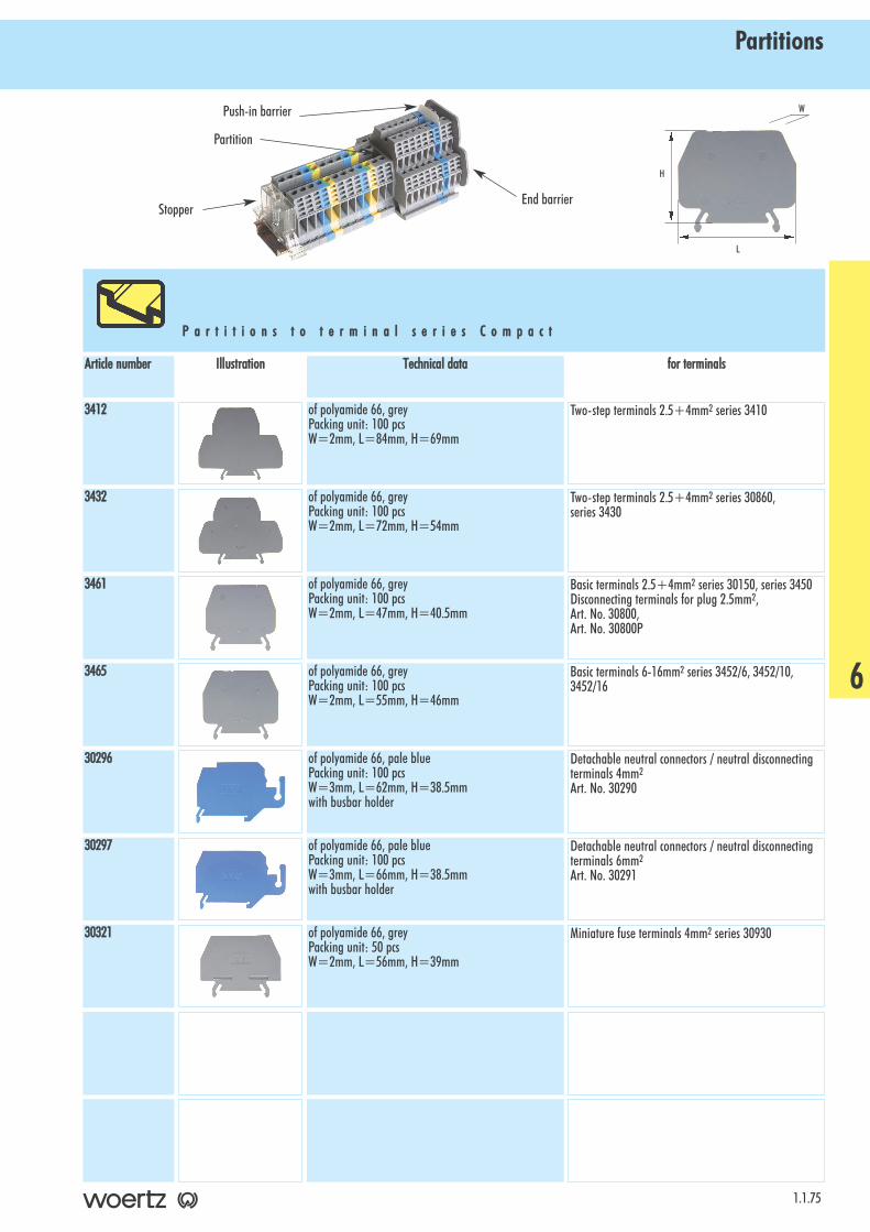
Partitions
1.1.75
P a r t i t i o n s tt o tt e r m i n a l ss e r i e s CC o m p a c t
for tterminalsTechnical ddataIllustrationArticle nnumber
Two-step terminals 2.5+4mm2 series 3410of polyamide 66, greyPacking unit: 100 pcsW=2mm, L=84mm, H=69mm
3412
Two-step terminals 2.5+4mm2 series 30860, series 3430
of polyamide 66, greyPacking unit: 100 pcsW=2mm, L=72mm, H=54mm
3432
Basic terminals 2.5+4mm2 series 30150, series 3450Disconnecting terminals for plug 2.5mm2,Art. No. 30800, Art. No. 30800P
of polyamide 66, greyPacking unit: 100 pcsW=2mm, L=47mm, H=40.5mm
3461
Basic terminals 6-16mm2 series 3452/6, 3452/10,3452/16
of polyamide 66, greyPacking unit: 100 pcsW=2mm, L=55mm, H=46mm
3465
Detachable neutral connectors / neutral disconnectingterminals 4mm2
Art. No. 30290
of polyamide 66, pale bluePacking unit: 100 pcsW=3mm, L=62mm, H=38.5mmwith busbar holder
30296
Detachable neutral connectors / neutral disconnectingterminals 6mm2
Art. No. 30291
of polyamide 66, pale bluePacking unit: 100 pcsW=3mm, L=66mm, H=38.5mmwith busbar holder
30297
Miniature fuse terminals 4mm2 series 30930of polyamide 66, greyPacking unit: 50 pcsW=2mm, L=56mm, H=39mm
30321
H
L
W
6
End barrier
Push-in barrier
Stopper
Partition
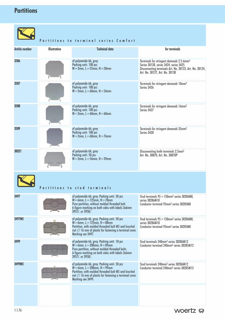
Partitions
1.1.76
P a r t i t i o n s tt o tt e r m i n a l ss e r i e s CC o m f o r t
for tterminalsTechnical ddataIllustrationArticle nnumber
Terminals for stringent demands 2.5-6mm2
Series 30128, series 3424, series 3425Disconnecting terminals Art. No. 30123, Art. No. 30124,Art. No. 30127, Art. No. 30130
of polyamide 66, greyPacking unit: 100 pcsW=2mm, L=55mm, H=50mm
3506
Terminals for stringent demands 10mm2
Series 3426of polyamide 66, greyPacking unit: 100 pcsW=2mm, L=60mm, H=56mm
3507
Terminals for stringent demands 16mm2
Series 3427of polyamide 66, greyPacking unit: 100 pcsW=2mm, L=60mm, H=60mm
3508
Terminals for stringent demands 35mm2
Series 3428of polyamide 66, greyPacking unit: 100 pcsW=2mm, L=68mm, H=76mm
3509
Disconnecting knife terminals 2.5mm2
Art. No. 30870, Art. No. 30870Pof polyamide 66, greyPacking unit: 50 pcsW=2mm, L=56mm, H=39mm
30321
Stud terminals 95+150mm2 series 30286M8, series 30286M10Conductor terminal 95mm2 series 30285M8
of polyamide 66, grey. Packing unit: 50 pcsW=6mm, L=125mm, H=70mmPure partition, without molded threaded bolt.6-figure marking on both sides with labels 3x6mm3957/. or 3958/.
3497
Stud terminals 95+150mm2 series 30286M8, series 30286M10Conductor terminal 95mm2 series 30285M8
of polyamide 66, grey. Packing unit: 50 pcsW=6mm, L=125mm, H=80mmPartition, with molded threaded bolt M5 and knurlednut ∅ 16 mm of plastic for fastening a terminal cover.Marking see 3497.
3497M5
Stud terminals 240mm2 series 30286M12Conductor terminal 240mm2 series 30285M12
of polyamide 66, grey. Packing unit: 10 pcsW=6mm, L=200mm, H=89mmPure partition, without molded threaded bolts.6-figure marking on both sides with labels 3x6mm3957/. or 3958/.
3499
Stud terminals 240mm2 series 30286M12Conductor terminal 240mm2 series 30285M12
of polyamide 66, grey. Packing unit: 50 pcsW=6mm, L=200mm, H=99mmPartition, with molded threaded bolt M5 and knurlednut ∅ 16 mm of plastic for fastening a terminal cover.Marking see 3499.
3499M5
P a r t i t i o n s tt o ss t u d tt e r m i n a l s
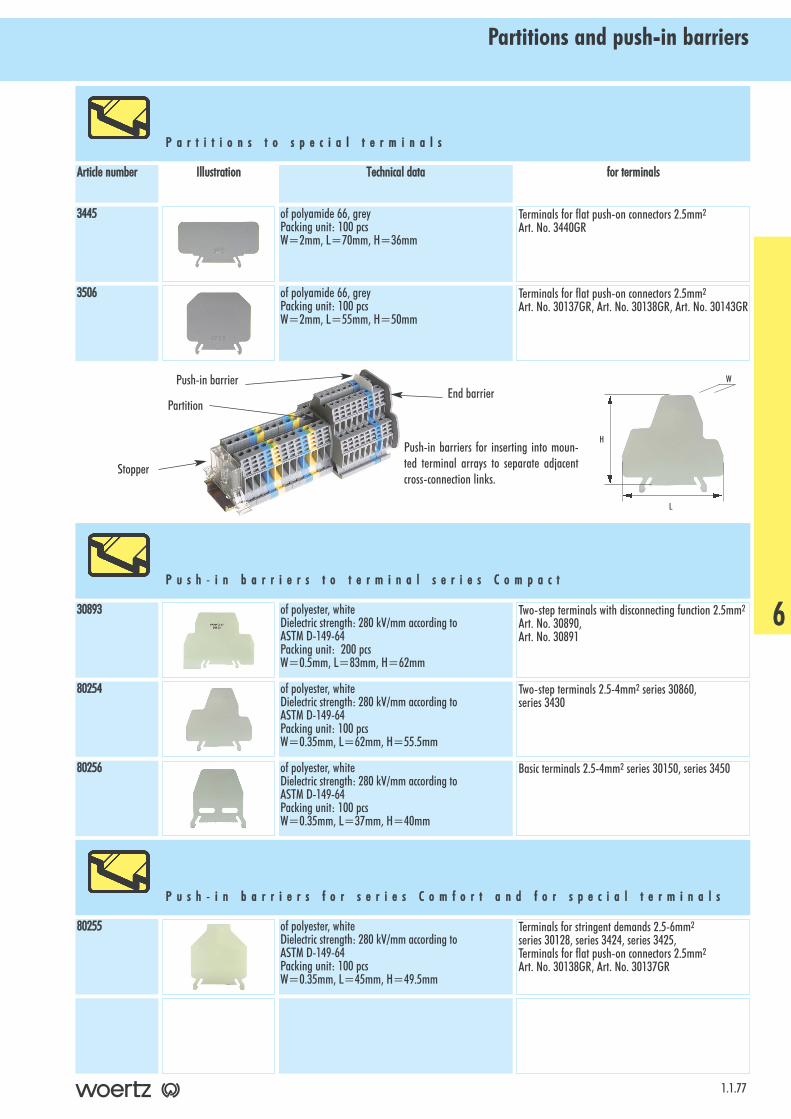
Partitions and push-in barriers
1.1.77
P a r t i t i o n s tt o ss p e c i a l tt e r m i n a l s
for tterminalsTechnical ddataIllustrationArticle nnumber
Terminals for flat push-on connectors 2.5mm2
Art. No. 3440GRof polyamide 66, greyPacking unit: 100 pcsW=2mm, L=70mm, H=36mm
3445
Terminals for flat push-on connectors 2.5mm2
Art. No. 30137GR, Art. No. 30138GR, Art. No. 30143GRof polyamide 66, greyPacking unit: 100 pcsW=2mm, L=55mm, H=50mm
3506
Two-step terminals with disconnecting function 2.5mm2
Art. No. 30890, Art. No. 30891
of polyester, whiteDielectric strength: 280 kV/mm according toASTM D-149-64Packing unit: 200 pcsW=0.5mm, L=83mm, H=62mm
30893
Two-step terminals 2.5-4mm2 series 30860, series 3430
of polyester, whiteDielectric strength: 280 kV/mm according toASTM D-149-64Packing unit: 100 pcsW=0.35mm, L=62mm, H=55.5mm
80254
Basic terminals 2.5-4mm2 series 30150, series 3450of polyester, whiteDielectric strength: 280 kV/mm according toASTM D-149-64Packing unit: 100 pcsW=0.35mm, L=37mm, H=40mm
80256
Terminals for stringent demands 2.5-6mm2
series 30128, series 3424, series 3425, Terminals for flat push-on connectors 2.5mm2
Art. No. 30138GR, Art. No. 30137GR
of polyester, whiteDielectric strength: 280 kV/mm according toASTM D-149-64Packing unit: 100 pcsW=0.35mm, L=45mm, H=49.5mm
80255
Push-in barriers for inserting into moun-ted terminal arrays to separate adjacentcross-connection links.
P u s h - ii n bb a r r i e r s tt o tt e r m i n a l ss e r i e s CC o m p a c t
P u s h - ii n bb a r r i e r s ff o r ss e r i e s CC o m f o r t aa n d ff o r ss p e c i a l tt e r m i n a l s
H
L
W
6
End barrierPush-in barrier
Stopper
Partition
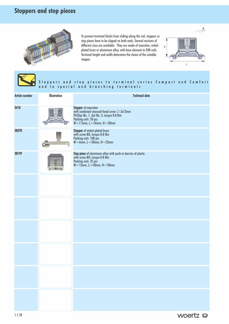
Stoppers and stop pieces
1.1.78
To prevent terminal blocks from sliding along the rail, stoppers orstop pieces have to be clipped on both ends. Several versions ofdifferent sizes are available. They are made of macrolon, nickel-plated brass or aluminum alloy, with base element to DIN rails.Terminal height and width determine the choice of the suitablestopper.
S t o p p e r s aa n d ss t o p pp i e c e s tt o tt e r m i n a l ss e r i e s CC o m p a c t aa n d CC o m f o r ta n d tt o ss p e c i a l aa n d bb r a n c h i n g tt e r m i n a l s
Technical ddataIllustrationArticle nnumber
Stopper of macrolonwith combined recessed-head screw ∅ 3x12mmPhillips No. 1, slot No. 3, torque 0.8 NmPacking unit: 50 pcsW=7.5mm, L=56mm, H=30mm
3418
Stopper of nickel-plated brasswith screw M3, torque 0.8 NmPacking unit: 100 pcsW=6mm, L=50mm, H=23mm
30370
H
L
W
Stop ppiece of aluminum alloy with push-in barrier of plasticwith screw M3, torque 0.8 NmPacking unit: 25 pcsW=12mm, L=50mm, H=50mm
30199
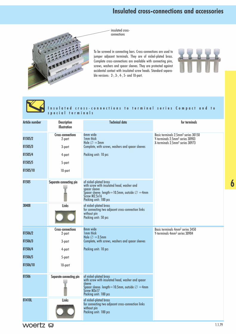
Insulated cross-connections and accessories
1.1.79
To be screwed in connecting bars. Cross-connections are used tojumper adjacent terminals. They are of nickel-plated brass.Complete cross-connections are available with connecting pins,screws, washers and spacer sleeves. They are protected againstaccidental contact with insulated screw heads. Standard separa-ble versions: 2-, 3-, 4-, 5- and 10-part.
I n s u l a t e d cc r o s s - cc o n n e c t i o n s tt o tt e r m i n a l ss e r i e s CC o m p a c t aa n d tt os p e c i a l tt e r m i n a l s
for tterminalsTechnical ddataDescriptionIllustration
Article nnumber
Basic terminals 2.5mm2 series 30150Y-terminals 2.5mm2 series 30903X-terminals 2.5mm2 series 30973
6mm wide1mm thickHole ∅ =3mmComplete, with screws, washers and spacer sleeves
Packing unit: 10 pcs
81505/2
81505/3
81505/4
81505/5
81505/10
of nickel-plated brasswith screw with insulated head, washer andspacer sleeveSpacer sleeve: length=10.5mm, outside ∅ =4mmScrew M2.5x16Packing unit: 100 pcs
81505
of nickel-plated brassfor connecting two adjacent cross-connection linkswithout pinPacking unit: 50 pcs
30408
Cross-cconnections2-part
3-part
4-part
5-part
10-part
Separate cconnecting ppin
Links
Basic terminals 4mm2 series 3450Y-terminals 4mm2 series 30904
8mm wide1mm thickHole ∅ =3.5mmComplete, with screws, washers and spacer sleeves
Packing unit: 10 pcs
81506/2
81506/3
81506/4
81506/5
81506/10
of nickel-plated brasswith screw with insulated head, washer and spacersleeveSpacer sleeve: length=10.5mm, outside ∅ =4mmScrew M3x17Packing unit: 100 pcs
81506
of nickel-plated brassfor connecting two adjacent cross-connection linkswithout pinPacking unit: 100 pcs
81410L
Cross-cconnections2-part
3-part
4-part
5-part
10-part
Separate cconnecting ppin
Links
6
insulated cross-connections
Insulated cross-connections and accessories
1.1.80
for tterminalsTechnical ddataDescriptionIllustration
Article nnumber
Basic terminals 6mm2 series 3452/6Two-step terminals 6mm2 series 3410
7.5mm wide1.5mm thickHole ∅ =3.5mmComplete, with screws, washers and spacer sleeves
Packing unit: 10 pcs
81507/2
81507/3
81507/4
81507/5
81507/10
of nickel-plated brasswith screw with insulated head, washer and spacer sleeveSpacer sleeve: length=10.5mm, outside ∅ =4mmScrew M3x17Packing unit: 100 pcs
81506
of nickel-plated brassfor connecting two adjacent cross-connection linkswithout pinPacking unit: 100 pcs
81452L
Cross-cconnections2-part
3-part
4-part
5-part
10-part
Separate cconnecting ppin
Links
Basic terminals 10mm2 series 3452/108mm wide1.5mm thickHole ∅ =3.5mmComplete, with screws, washers and spacer sleeves
Packing unit: 10 pcs
81508/2
81508/3
81508/4
81508/5
81508/10
of nickel-plated brasswith screw with insulated head, washer and spacersleevesSpecer sleeve: length=13.5mm, outside ∅ =5mmScrew M3x20Packing unit: 100 pcs
81508
of nickel-plated brassfor connecting two adjacent cross-connection linkswithout pinPacking unit: 100 pcs
81412L
Cross-cconnections2-part
3-part
4-part
5-part
10-part
Separate cconnecting ppin
Links
Two-step terminals 2.5mm2 series 30860Return terminal 2.5mm2 Art. No. 30810
6mm wide1mm thickHole ∅ =3mmComplete, with screws, washers and spacer sleeves
Packing unit: 10 pcs
81525/2
81525/3
81525/4
81525/5
81525/10
of nickel-plated brasswith screw with insulated head, washer and spacersleeveSpacer sleeve: length=9.5mm, outside ∅ =4mmScrew M2.5x16Packing unit: 100 pcs
81525
of nickel-plated brassfor connecting two adjacent cross-connection linkswithout pinPacking unit: 50 pcs
30408
Cross-cconnections2-part
3-part
4-part
5-part
10-part
Separate cconnecting ppin
Links
Insulated cross-connections and accessories
1.1.81
for tterminalsTechnical ddataDescriptionIllustration
Article nnumber
Two-step terminals 4mm2 series 3430, 3430/1PTwo-step terminals with disconnecting function 2.5mm2
Art. No. 30890, Art. No. 30891Terminals for flat push-on connectors 2.5mm2 Art. No.30138GR, Art. No. 30137GR
6mm wide1mm thickHole ∅ =3.5mmComplete, with screws, washers and spacer sleeves
Packing unit: 10 pcs
81526/2
81526/3
81526/4
81526/5
81526/10
of nickel-plated brasswith screw with insulated head, washer and spacersleeveSpacer sleeve: length=9mm, outside ∅ =4mm ScrewM3x14Packing unit: 100 pcs
81526
of nickel-plated brassfor connecting two adjacent cross-connection linkswithout pinPacking unit: 100 pcs
30441
Cross-cconnections 2-part
3-part
4-part
5-part
10-part
Separate cconnecting ppin
Links
Three-step terminals for proximity switches 2.5mm2
Series 30400, 304036mm wide1mm thickHole ∅ =3mmComplete, with screws, washers and spacer sleeves
Packing unit: 10 pcs
81535/2
81535/3
81535/4
81535/5
81535/10
of nickel-plated brasswith screw with insulated head, washer and spacersleeveSpacer sleeve: length=4mm, outside ∅ =4mm ScrewM2.5x8
81535
of nickel-plated brassfor connecting two adjacent cross-connection linkswithout pinPacking unit: 50 pcs
30408
Cross-cconnections 2-part
3-part
4-part
5-part
10-part
Separate cconnecting ppin
Links
Three-step installation terminals 4mm2 series 30430,30431/1, 30431/2, 30432
6mm wide1mm thickHole ∅ =3mmComplete, with screws, washers and spacer sleeves
Packing unit: 10 pcs
81536/2
81536/3
81536/4
81536/5
81536/10
of nickel-plated brasswith screw with insulated head, washer and spacersleeveSpacer sleeve: length=4mm, outside ∅ =4mm ScrewM2.5x10Packing unit: 100 pcs
81536
of nickel-plated brassfor connecting two adjacent cross-connection linkswithout pinPacking unit: 100 pcs
30441
Cross-cconnections2-part
3-part
4-part
5-part
10-part
Separate cconnecting ppin
Links
6
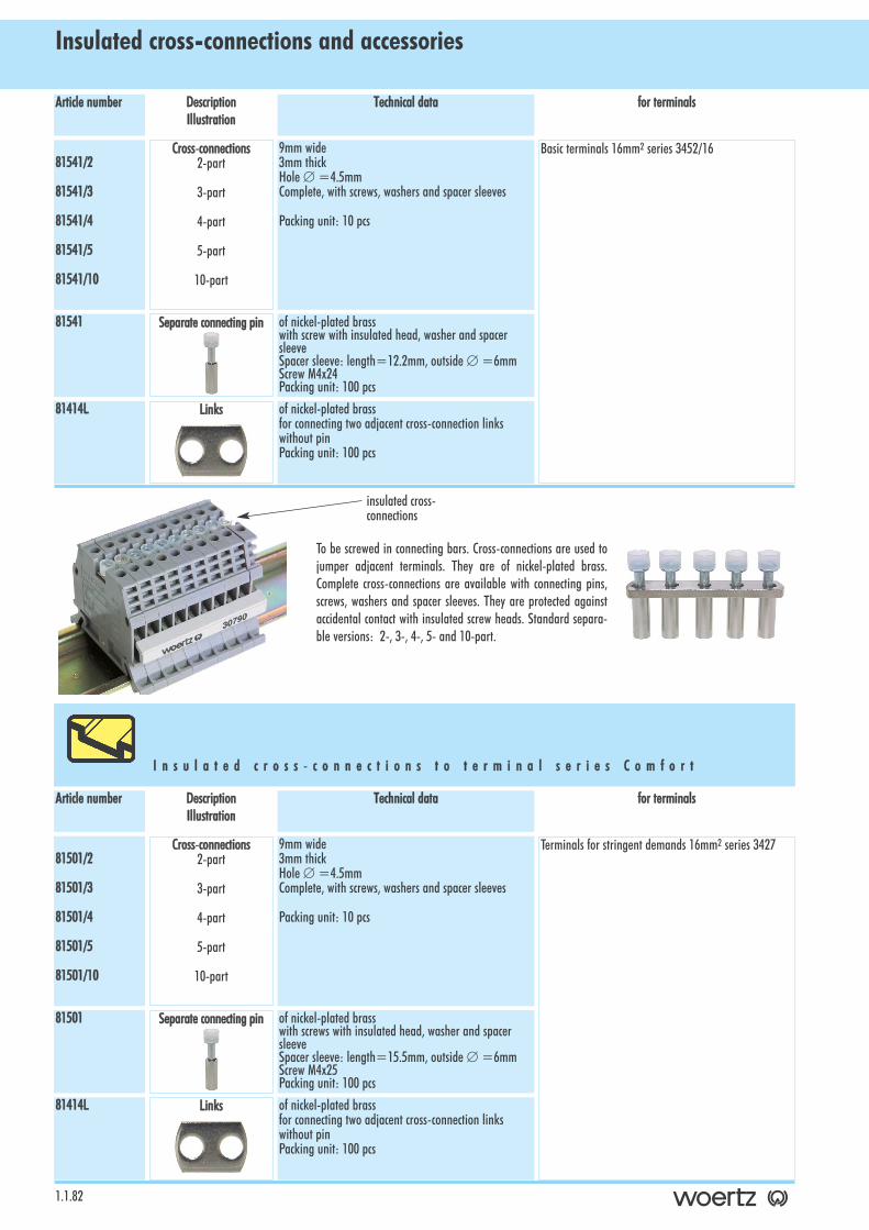
Insulated cross-connections and accessories
1.1.82
for tterminalsTechnical ddataDescriptionIllustration
Article nnumber
To be screwed in connecting bars. Cross-connections are used tojumper adjacent terminals. They are of nickel-plated brass.Complete cross-connections are available with connecting pins,screws, washers and spacer sleeves. They are protected againstaccidental contact with insulated screw heads. Standard separa-ble versions: 2-, 3-, 4-, 5- and 10-part.
I n s u l a t e d cc r o s s - cc o n n e c t i o n s tt o tt e r m i n a l ss e r i e s CC o m f o r t
Basic terminals 16mm2 series 3452/169mm wide3mm thickHole ∅ =4.5mmComplete, with screws, washers and spacer sleeves
Packing unit: 10 pcs
81541/2
81541/3
81541/4
81541/5
81541/10
of nickel-plated brasswith screw with insulated head, washer and spacersleeveSpacer sleeve: length=12.2mm, outside ∅ =6mmScrew M4x24Packing unit: 100 pcs
81541
of nickel-plated brassfor connecting two adjacent cross-connection linkswithout pinPacking unit: 100 pcs
81414L
Cross-cconnections2-part
3-part
4-part
5-part
10-part
Separate cconnecting ppin
Links
Terminals for stringent demands 16mm2 series 34279mm wide3mm thickHole ∅ =4.5mmComplete, with screws, washers and spacer sleeves
Packing unit: 10 pcs
81501/2
81501/3
81501/4
81501/5
81501/10
of nickel-plated brasswith screws with insulated head, washer and spacersleeveSpacer sleeve: length=15.5mm, outside ∅ =6mmScrew M4x25Packing unit: 100 pcs
81501
of nickel-plated brassfor connecting two adjacent cross-connection linkswithout pinPacking unit: 100 pcs
81414L
Cross-cconnections2-part
3-part
4-part
5-part
10-part
Separate cconnecting ppin
Links
for tterminalsTechnical ddataDescriptionIllustration
Article nnumber
insulated cross-connections
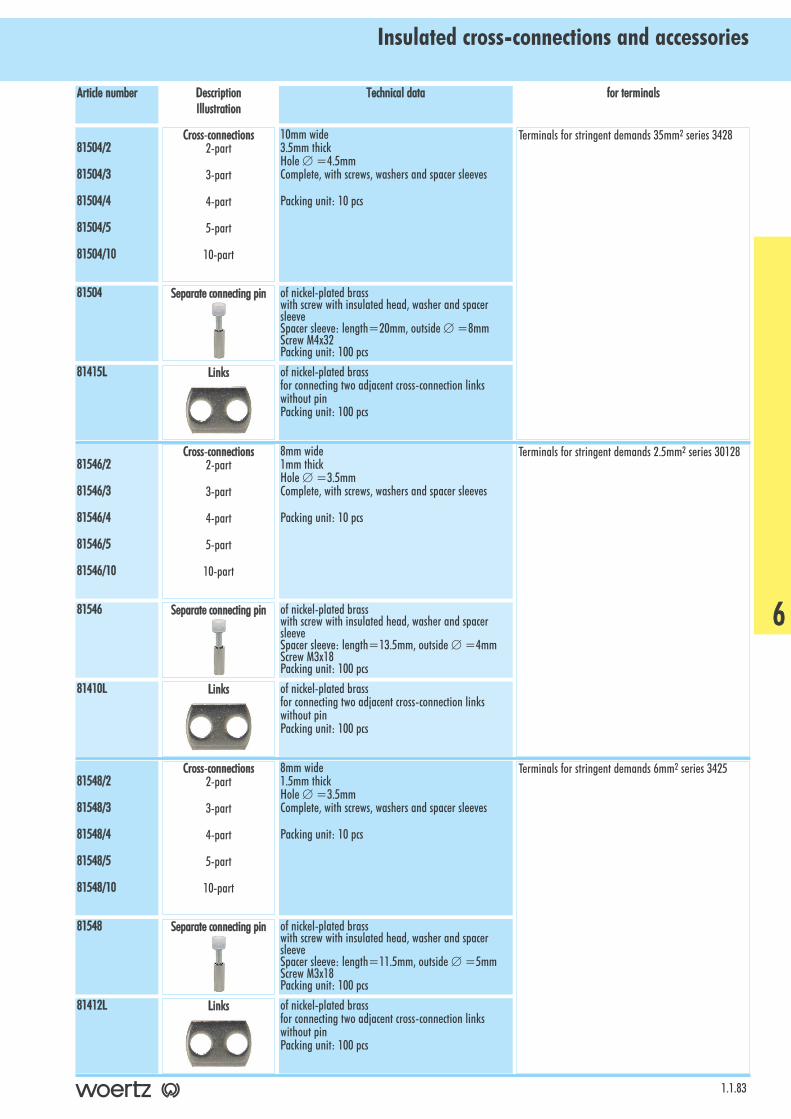
Insulated cross-connections and accessories
1.1.83
for tterminalsTechnical ddataDescriptionIllustration
Article nnumber
Terminals for stringent demands 6mm2 series 34258mm wide1.5mm thickHole ∅ =3.5mmComplete, with screws, washers and spacer sleeves
Packing unit: 10 pcs
81548/2
81548/3
81548/4
81548/5
81548/10
of nickel-plated brasswith screw with insulated head, washer and spacersleeveSpacer sleeve: length=11.5mm, outside ∅ =5mmScrew M3x18Packing unit: 100 pcs
81548
of nickel-plated brassfor connecting two adjacent cross-connection linkswithout pinPacking unit: 100 pcs
81412L
Cross-cconnections 2-part
3-part
4-part
5-part
10-part
Separate cconnecting ppin
Links
Terminals for stringent demands 35mm2 series 342810mm wide3.5mm thickHole ∅ =4.5mmComplete, with screws, washers and spacer sleeves
Packing unit: 10 pcs
81504/2
81504/3
81504/4
81504/5
81504/10
of nickel-plated brasswith screw with insulated head, washer and spacersleeveSpacer sleeve: length=20mm, outside ∅ =8mmScrew M4x32Packing unit: 100 pcs
81504
of nickel-plated brassfor connecting two adjacent cross-connection linkswithout pinPacking unit: 100 pcs
81415L
Cross-cconnections2-part
3-part
4-part
5-part
10-part
Separate cconnecting ppin
Links
Terminals for stringent demands 2.5mm2 series 301288mm wide1mm thickHole ∅ =3.5mmComplete, with screws, washers and spacer sleeves
Packing unit: 10 pcs
81546/2
81546/3
81546/4
81546/5
81546/10
of nickel-plated brasswith screw with insulated head, washer and spacersleeveSpacer sleeve: length=13.5mm, outside ∅ =4mmScrew M3x18Packing unit: 100 pcs
81546
of nickel-plated brassfor connecting two adjacent cross-connection linkswithout pinPacking unit: 100 pcs
81410L
Cross-cconnections2-part
3-part
4-part
5-part
10-part
Separate cconnecting ppin
Links
6
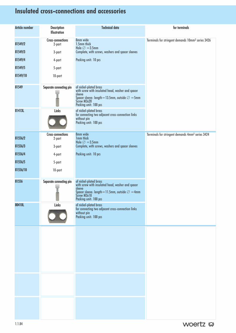
Insulated cross-connections and accessories
1.1.84
for tterminalsTechnical ddataDescriptionIllustration
Article nnumber
Terminals for stringent demands 4mm2 series 34248mm wide1mm thickHole ∅ =3.5mmComplete, with screws, washers and spacer sleeves
Packing unit: 10 pcs
81556/2
81556/3
81556/4
81556/5
81556/10
of nickel-plated brasswith screw with insulated head, washer and spacersleeveSpacer sleeve: length=11.5mm, outside ∅ =4mmScrew M3x18Packing unit: 100 pcs
81556
of nickel-plated brassfor connecting two adjacent cross-connection linkswithout pinPacking unit: 100 pcs
80410L
Cross-cconnections2-part
3-part
4-part
5-part
10-part
Separate cconnecting ppin
Links
Terminals for stringent demands 10mm2 series 34268mm wide1.5mm thickHole ∅ =3.5mmComplete, with screws, washers and spacer sleeves
Packing unit: 10 pcs
81549/2
81549/3
81549/4
81549/5
81549/10
of nickel-plated brasswith screw with insulated head, washer and spacersleeveSpacer sleeve: length=13.5mm, outside ∅ =5mmScrew M3x20Packing unit: 100 pcs
81549
of nickel-plated brassfor connecting two adjacent cross-connection linkswithout pinPacking unit: 100 pcs
81413L
Cross-cconnections 2-part
3-part
4-part
5-part
10-part
Separate cconnecting ppin
Links
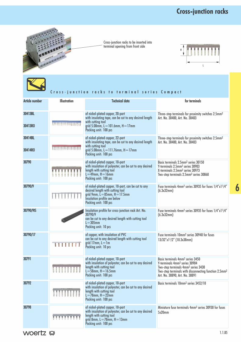
Cross-junction racks
1.1.85
C r o s s - jj u n c t i o n rr a c k s tt o tt e r m i n a l ss e r i e s CC o m p a c t
for tterminalsTechnical ddataIllustrationArticle nnumber
Three-step terminals for proximity switches 2.5mm2
Art. No. 30400, Art. No. 30403of nickel-plated copper, 20-partwith insulating tape, can be cut to any desired lengthwith cutting toolgrid 5.08mm, L=101.6mm, H=17mmPacking unit: 100 pcs
30413BL
30413RO
Three-step terminals for proximity switches 2.5mm2
Art. No. 30400, Art. No. 30403of nickel-plated copper, 22-partwith insulating tape, can be cut to any desired lengthwith cutting toolgrid 5.08mm, L=111.76mm, H=17mmPacking unit: 100 pcs
30414BL
30414RO
Basic terminals 2.5mm2 series 30150Y-terminals 2.5mm2 series 30903X-terminals 2.5mm2 series 30973Two-step terminals 2.5mm2 series 30860
of nickel-plated copper, 10-partwith insulation of polyester, can be cut to any desiredlength with cutting toolL=49mm, H=16mmPacking unit: 100 pcs
30790
Fuse terminals 4mm2 series 30935 for fuses 1/4”x11/4”(6.3x32mm)
of nickel-plated copper, 10-part, can be cut to anydesired length with cutting toolgrid 9mm, L=85mm, H=17.5mmInsulation profile see belowPacking unit: 100 pcs
30790/9
Fuse terminals 4mm2 series 30935 for fuses 1/4”x11/4”(6.3x32mm)
Insulation profile for cross-junction rack Art. No.30790/9can be cut to any desired length with cutting toolL=305mmPacking unit: 10 pcs
30790/9IS
Basic terminals 4mm2 series 3450Y-terminals 4mm2 series 30904Two-step terminals 4mm2 series 3430Two-step terminals with disconnecting function 2.5mm2
Art. No. 30890, Art. No. 30891
of nickel-plated copper, 10-partwith insulation of polyester, can be cut to any desiredlength with cutting toolL=58mm, H=16.5mmPacking unit: 100 pcs
30791
Basic terminals 10mm2 series 3452/10of nickel-plated copper, 10-partwith insulation of polyester, can be cut to any desiredlength with cutting toolL=78mm, H=22mmPacking unit: 100 pcs
30792
Miniature fuse terminals 4mm2 series 30930 for fuses5x20mm
of nickel-plated copper, 10-partwith insulation of polyester, can be cut to any desiredlength with cutting toolgrid 8mm, L=78mm, H=13mmPacking unit: 100 pcs
30798
H
L
Fuse terminals 10mm2 series 30940 for fuses13/32”x11/2” (10.3x38mm)
of copper, with insulation of PVCcan be cut to any desired length with cutting toolgrid 17mm, L=1mPacking unit: 10 pcs
30790/17
6
Cross-junction racks to be inserted intoterminal opening from front side

Cross-junction racks
1.1.86
C r o s s - jj u n c t i o n rr a c k s tt o tt e r m i n a l ss e r i e s CC o m f o r t
for tterminalsTechnical ddataIllustrationArticle nnumber
Lateral disconnecting terminals 10mm2 Art. No. 30172of nickel-plated brass, 10-part, can be cut to any desired length with cuttingtoolfor clamping with screw headPacking unit: 50 pcs
30179
Terminals for stringent demands 2.5mm2 series 30128Knife disconnecting terminals 2.5mm2 Art. No. 30870,Art. No. 30870P
Terminal for flat push-on connectors 2.5mm2
Art. No. 3440GRof copper, tinned, 20-part (different number of parts onrequest), with insulating tape, can be cut to any desiredlength with cutting toolL=132mm, H=25mmPacking unit: 50 pcs
30420/20
of nickel-plated copper, 10-partwith insulation of polyester, can be cut to any desiredlength with cutting toolL=49mm, H=16mmPacking unit: 100 pcs
30790
Terminals for stringent demands 4mm2 series 3424of nickel-plated copper, 10-partwith insulation of polyester, can be cut to any desiredlength with cutting toolL=58mm, H=16.5mmPacking unit: 100 pcs
30791
Terminals for stringent demands 6mm2 series 3425of nickel-plated copper, 10-partwith insulation of polyester, can be cut to any desiredlength with cutting toolL=78mm, H=22mmPacking unit: 100 pcs
30792
C r o s s - jj u n c t i o n rr a c k s tt o ss p e c i a l tt e r m i n a l s
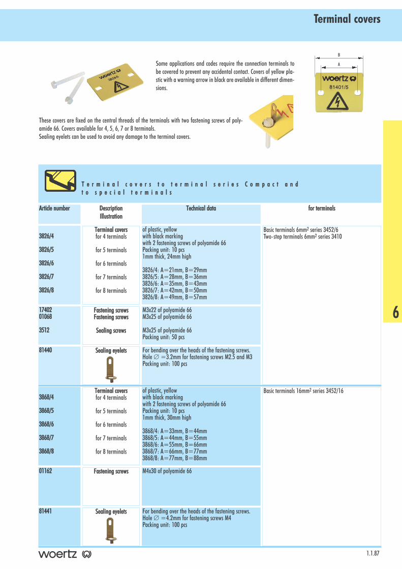
Terminal covers
1.1.87
Some applications and codes require the connection terminals tobe covered to prevent any accidental contact. Covers of yellow pla-stic with a warning arrow in black are available in different dimen-sions.
These covers are fixed on the central threads of the terminals with two fastening screws of poly-amide 66. Covers available for 4, 5, 6, 7 or 8 terminals. Sealing eyelets can be used to avoid any damage to the terminal covers.
T e r m i n a l cc o v e r s tt o tt e r m i n a l ss e r i e s CC o m p a c t aa n d t o ss p e c i a l tt e r m i n a l s
for tterminalsTechnical ddataDescriptionIllustration
Article nnumber
Basic terminals 6mm2 series 3452/6Two-step terminals 6mm2 series 3410
of plastic, yellowwith black markingwith 2 fastening screws of polyamide 66Packing unit: 10 pcs1mm thick, 24mm high
3826/4: A=21mm, B=29mm3826/5: A=28mm, B=36mm3826/6: A=35mm, B=43mm3826/7: A=42mm, B=50mm3826/8: A=49mm, B=57mm
3826/4
3826/5
3826/6
3826/7
3826/8
For bending over the heads of the fastening screws.Hole ∅ =3.2mm for fastening screws M2.5 and M3Packing unit: 100 pcs
81440
M3x22 of polyamide 66M3x25 of polyamide 66
M3x25 of polyamide 66Packing unit: 50 pcs
1740201068
3512
Basic terminals 16mm2 series 3452/16of plastic, yellowwith black markingwith 2 fastening screws of polyamide 66Packing unit: 10 pcs1mm thick, 30mm high
3868/4: A=33mm, B=44mm3868/5: A=44mm, B=55mm3868/6: A=55mm, B=66mm3868/7: A=66mm, B=77mm3868/8: A=77mm, B=88mm
3868/4
3868/5
3868/6
3868/7
3868/8
M4x30 of polyamide 6601162
For bending over the heads of the fastening screws.Hole ∅ =4.2mm for fastening screws M4Packing unit: 100 pcs
81441
A
Terminal ccoversfor 4 terminals
for 5 terminals
for 6 terminals
for 7 terminals
for 8 terminals
Terminal ccoversfor 4 terminals
for 5 terminals
for 6 terminals
for 7 terminals
for 8 terminals
Fastening sscrewsFastening sscrews
Sealing sscrews
Sealing eeyelets
Fastening sscrews
Sealing eeyelets
B
6

Terminal covers
1.1.88
for tterminalsTechnical ddataDescriptionIllustration
Article nnumber
Basic terminals 4mm2 series 3450Y-terminals 4mm2 series 30904
Terminals for flat push-on connectors 2.5mm2
Art. No. 30138GR*, Art. No. 30137GR
* for Art. No. 30138GR use only fastening screwsM3x22 Art. No. 17402
of plastic, yellowwith black markingwith 2 fastening screws of polyamide 66Packing unit: 10 pcs1mm thick, 24mm high
3886/4: A=18mm, B=26mm3886/5: A=24mm, B=32mm3886/6: A=30mm, B=38mm3886/7: A=36mm, B=44mm3886/8: A=42mm, B=50mm
3886/4
3886/5
3886/6
3886/7
3886/8
For bending over the heads of the fastening screws.Hole ∅ =3.2mm for fastening screws M2.5 and M3Packing unit: 100 pcs
81440
M3x22 of polyamide 66M3x25 of polyamide 66
M3x25 of polyamide 66Packing unit: 50 pcs
1740201068
3512
Basic terminals 16mm2 series 3452/10of plastic, yellowwith black markingwith 2 fastening screws of polyamide 66Packing unit: 10 pcs1mm thick, 24mm high
3887/4: A=24mm, B=32mm3887/5: A=32mm, B=40mm3887/6: A=40mm, B=48mm3887/7: A=48mm, B=56mm3887/8: A=56mm, B=64mm
3887/4
3887/5
3887/6
3887/7
3887/8
M3x25 of polyamide 66
M3x25 of polyamide 66Packing unit: 50 pcs
01068
3512
For bending over the heads of the fastening screws.Hole ∅ =3.2mm for fastening screws M2.5 and M3Packing unit: 100 pcs
81440
Terminal ccoversfor 4 terminals
for 5 terminals
for 6 terminals
for 7 terminals
for 8 terminals
Terminal ccoversfor 4 terminals
for 5 terminals
for 6 terminals
for 7 terminals
for 8 terminals
Fastening sscrewsFastening sscrews
Sealing sscrews
Sealing eeyelets
Fastening sscrews
Sealing sscrews
Sealing eeyelets
Two-step terminals 4mm2 series 3430of plastic, yellowwith black markingwith 2 fastening screws of polyamide 66Packing unit: 10 pcs1mm thick, 24 mm high
3894/4: A=18mm, B=26mm3894/5: A=24mm, B=32mm3894/6: A=30mm, B=38mm3894/7: A=36mm, B=44mm3894/8: A=42mm, B=50mm
3894/4
3894/5
3894/6
3894/7
3894/8
M3x20 of polyamide 66
M3x25 of polyamide 66Packing unit: 50 pcs
01062
3512
For bending over the heads of the fastening screws.Hole ∅ =3.2mm for fastening screws M2.5 and M3Packing unit: 100 pcs
81440
Terminal ccoversfor 4 terminals
for 5 terminals
for 6 terminals
for 7 terminals
for 8 terminals
Fastening sscrews
Sealing sscrews
Sealing eeyelets
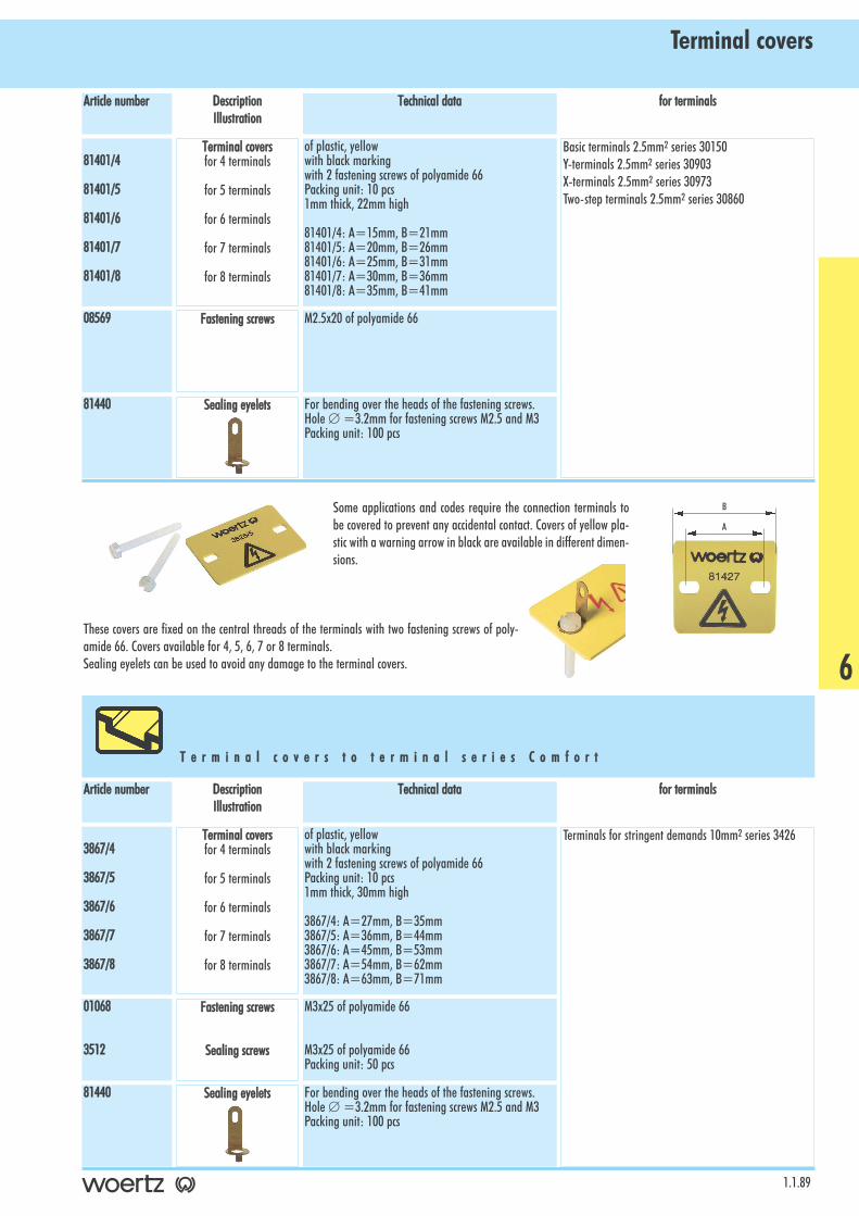
Terminal covers
1.1.89
for tterminalsTechnical ddataDescriptionIllustration
Article nnumber
Basic terminals 2.5mm2 series 30150Y-terminals 2.5mm2 series 30903X-terminals 2.5mm2 series 30973Two-step terminals 2.5mm2 series 30860
of plastic, yellowwith black markingwith 2 fastening screws of polyamide 66Packing unit: 10 pcs1mm thick, 22mm high
81401/4: A=15mm, B=21mm81401/5: A=20mm, B=26mm81401/6: A=25mm, B=31mm81401/7: A=30mm, B=36mm81401/8: A=35mm, B=41mm
81401/4
81401/5
81401/6
81401/7
81401/8
For bending over the heads of the fastening screws.Hole ∅ =3.2mm for fastening screws M2.5 and M3Packing unit: 100 pcs
81440
M2.5x20 of polyamide 6608569
Terminal ccoversfor 4 terminals
for 5 terminals
for 6 terminals
for 7 terminals
for 8 terminals
Fastening sscrews
Sealing eeyelets
Some applications and codes require the connection terminals tobe covered to prevent any accidental contact. Covers of yellow pla-stic with a warning arrow in black are available in different dimen-sions.
These covers are fixed on the central threads of the terminals with two fastening screws of poly-amide 66. Covers available for 4, 5, 6, 7 or 8 terminals. Sealing eyelets can be used to avoid any damage to the terminal covers.
T e r m i n a l cc o v e r s tt o tt e r m i n a l ss e r i e s CC o m f o r t
for tterminalsTechnical ddataDescriptionIllustration
Article nnumber
Terminals for stringent demands 10mm2 series 3426of plastic, yellowwith black markingwith 2 fastening screws of polyamide 66Packing unit: 10 pcs1mm thick, 30mm high
3867/4: A=27mm, B=35mm3867/5: A=36mm, B=44mm3867/6: A=45mm, B=53mm3867/7: A=54mm, B=62mm3867/8: A=63mm, B=71mm
3867/4
3867/5
3867/6
3867/7
3867/8
For bending over the heads of the fastening screws.Hole ∅ =3.2mm for fastening screws M2.5 and M3Packing unit: 100 pcs
81440
M3x25 of polyamide 66
M3x25 of polyamide 66Packing unit: 50 pcs
01068
3512
A
Terminal ccoversfor 4 terminals
for 5 terminals
for 6 terminals
for 7 terminals
for 8 terminals
Fastening sscrews
Sealing sscrews
Sealing eeyelets
B
6
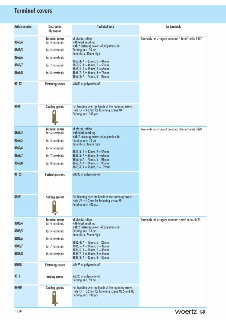
Terminal covers
1.1.90
for tterminalsTechnical ddataDescriptionIllustration
Article nnumber
Terminals for stringent demands 16mm2 series 3427of plastic, yellowwith black markingwith 2 fastening screws of polyamide 66Packing unit: 10 pcs1mm thick, 30mm high
3868/4: A=33mm, B=44mm3868/5: A=44mm, B=55mm3868/6: A=55mm, B=66mm3868/7: A=66mm, B=77mm3868/8: A=77mm, B=88mm
3868/4
3868/5
3868/6
3868/7
3868/8
For bending over the heads of the fastening screws.Hole ∅ =4.2mm for fastening screws M4Packing unit: 100 pcs
81441
M4x30 of polyamide 6601162
Terminals for stringent demands 35mm2 series 3428of plastic, yellowwith black markingwith 2 fastening screws of polyamide 66Packing unit: 10 pcs1mm thick, 37mm high
3869/4: A=42mm, B=53mm3869/5: A=56mm, B=67mm3869/6: A=70mm, B=81mm3869/7: A=84mm, B=95mm3869/8: A=98mm, B=109mm
3869/4
3869/5
3869/6
3869/7
3869/8
M4x35 of polyamide 6601165
For bending over the heads of the fastening screws.Hole ∅ =4.2mm for fastening screws M4Packing unit: 100 pcs
81441
Terminal ccoversfor 4 terminals
for 5 terminals
for 6 terminals
for 7 terminals
for 8 terminals
Terminal ccoversfor 4 terminals
for 5 terminals
for 6 terminals
for 7 terminals
for 8 terminals
Fastening sscrews
Sealing eeyelets
Fastening sscrews
Sealing eeyelets
Terminals for stringent demands 4mm2 series 3424of plastic, yellowwith black markingwith 2 fastening screws of polyamide 66Packing unit: 10 pcs1mm thick, 24mm high
3886/4: A=18mm, B=26mm3886/5: A=24mm, B=32mm3886/6: A=30mm, B=38mm3886/7: A=36mm, B=44mm3886/8: A=42mm, B=50mm
3886/4
3886/5
3886/6
3886/7
3886/8
For bending over the heads of the fastening screws.Hole ∅ =3.2mm for fastening screws M2.5 and M3Packing unit: 100 pcs
81440
M3x25 of polyamide 66
M3x25 of polyamide 66Packing unit: 50 pcs
01068
3512
Terminal ccoversfor 4 terminals
for 5 terminals
for 6 terminals
for 7 terminals
for 8 terminals
Fastening sscrews
Sealing sscrews
Sealing eeyelets
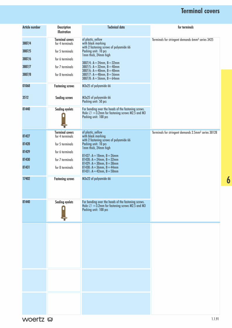
Terminal covers
1.1.91
for tterminalsTechnical ddataDescriptionIllustration
Article nnumber
Terminals for stringent demands 2.5mm2 series 30128of plastic, yellowwith black markingwith 2 fastening screws of polyamide 66Packing unit: 10 pcs1mm thick, 24mm high
81427: A=18mm, B=26mm81428: A=24mm, B=32mm81429: A=30mm, B=38mm81430: A=36mm, B=44mm81431: A=42mm, B=50mm
81427
81428
81429
81430
81431
M3x22 of polyamide 6617402
For bending over the heads of the fastening screws.Hole ∅ =3.2mm for fastening screws M2.5 and M3Packing unit: 100 pcs
81440
Terminal ccoversfor 4 terminals
for 5 terminals
for 6 terminals
for 7 terminals
for 8 terminals
Fastening sscrews
Sealing eeyelets
Terminals for stringent demands 6mm2 series 3425of plastic, yellowwith black markingwith 2 fastening screws of polyamide 66Packing unit: 10 pcs1mm thick, 24mm high
3887/4: A=24mm, B=32mm3887/5: A=32mm, B=40mm3887/6: A=40mm, B=48mm3887/7: A=48mm, B=56mm3887/8: A=56mm, B=64mm
3887/4
3887/5
3887/6
3887/7
3887/8
M3x25 of polyamide 66
M3x25 of polyamide 66Packing unit: 50 pcs
01068
3512
For bending over the heads of the fastening screws.Hole ∅ =3.2mm for fastening screws M2.5 and M3Packing unit: 100 pcs
81440
Terminal ccoversfor 4 terminals
for 5 terminals
for 6 terminals
for 7 terminals
for 8 terminals
Fastening sscrews
Sealing sscrews
Sealing eeyelets
6
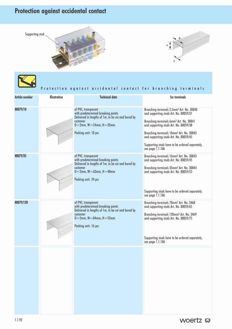
Protection against accidental contact
1.1.92
P r o t e c t i o n aa g a i n s t aa c c i d e n t a l cc o n t a c t ff o r bb r a n c h i n g tt e r m i n a l s
for tterminalsTechnical ddataIllustrationArticle nnumber
Branching terminals 2.5mm2 Art. No. 30840and supporting studs Art. No. 80059/31
Branching terminals 6mm2 Art. No. 30841and supporting studs Art. No. 80059/38
Branching terminals 10mm2 Art. No. 30842and supporting studs Art. No. 80059/45
Supporting studs have to be ordered separately,see page 1.1.106
of PVC, transparentwith predetermined breaking pointsDelivered in lengths of 1m, to be cut and bored bycustomerD=2mm, W=54mm, H=32mm
Packing unit: 18 pcs
80079/10
Branching terminals 16mm2 Art. No. 30843and supporting studs Art. No. 80059/45
Branching terminals 35mm2 Art. No. 30844and supporting studs Art. No. 80059/55
Supporting studs have to be ordered separately,see page 1.1.106
of PVC, transparentwith predetermined breaking pointsDelivered in lengths of 1m, to be cut and bored bycustomerD=2mm, W=62mm, H=40mm
Packing unit: 24 pcs
80079/35
Branching terminals 70mm2 Art. No. 3468and supporting studs Art. No. 80059/65
Branching terminals 120mm2 Art. No. 3469and supporting studs Art. No. 80059/75
Supporting studs have to be ordered separately,see page 1.1.106
of PVC, transparentwith predetermined breaking pointsDelivered in lengths of 1m, to be cut and bored bycustomerD=2mm, W=84mm, H=52mm
Packing unit: 16 pcs
80079/120
Supporting stud
H
W
D
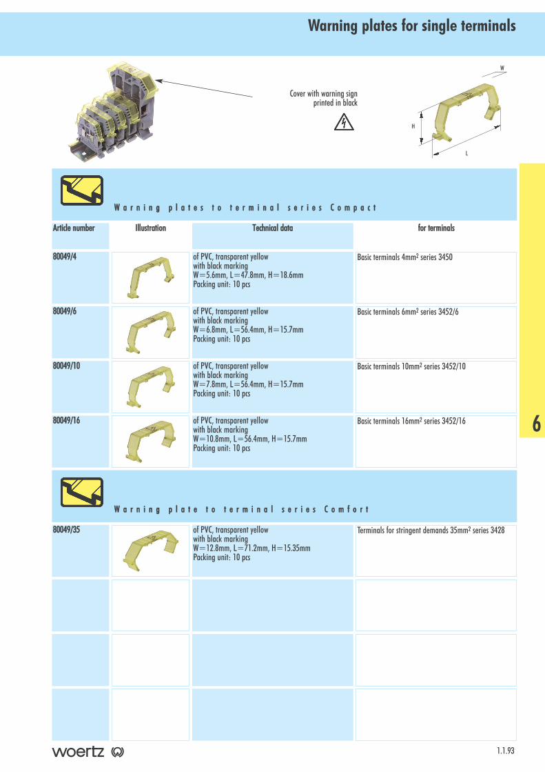
Warning plates for single terminals
1.1.93
W a r n i n g pp l a t e s tt o tt e r m i n a l ss e r i e s CC o m p a c t
for tterminalsTechnical ddataIllustrationArticle nnumber
Basic terminals 4mm2 series 3450of PVC, transparent yellowwith black markingW=5.6mm, L=47.8mm, H=18.6mmPacking unit: 10 pcs
80049/4
Basic terminals 6mm2 series 3452/6of PVC, transparent yellowwith black markingW=6.8mm, L=56.4mm, H=15.7mmPacking unit: 10 pcs
80049/6
Basic terminals 10mm2 series 3452/10of PVC, transparent yellowwith black markingW=7.8mm, L=56.4mm, H=15.7mmPacking unit: 10 pcs
80049/10
Basic terminals 16mm2 series 3452/16of PVC, transparent yellowwith black markingW=10.8mm, L=56.4mm, H=15.7mmPacking unit: 10 pcs
80049/16
Terminals for stringent demands 35mm2 series 3428of PVC, transparent yellowwith black markingW=12.8mm, L=71.2mm, H=15.35mmPacking unit: 10 pcs
80049/35
H
L
W
W a r n i n g pp l a t e tt o tt e r m i n a l ss e r i e s CC o m f o r t
6
Cover with warning sign printed in black

Covers to cross-connectors
1.1.94
C o v e r s tt o cc r o s s - cc o n n e c t o r s ff o r tt e r m i n a l ss e r i e s CC o m p a c t
for tterminalsTechnical ddataIllustrationArticle nnumber
Basic terminals 2.5mm2 series 30150Y-terminals 2.5mm2 series 30903X-terminals 2.5mm2 series 30973Two-step terminals 2.5mm2 series 30860Two-step terminals 4mm2 series 3430
of thermoplastic, whiteH=4.55mm, W=9.5mm, C=6.6mm, 280mm longProtection against accidental contact, also usable foradditional marking.Packing unit: 25 pcs
30421
Basic terminals 4mm2 series 3450Basic terminals 6mm2 series 3452/6Basic terminals 10mm2 series 3452/10Y-terminals 4mm2 series 30904Terminals for stringent demands 2.5mm2 series 30128Terminals for stringent demands 4mm2 series 3424Terminals for stringent demands 6mm2 series 3425Terminals for stringent demands 10mm2 series 3426
of thermoplastic, whiteH=4.55mm, W=9.5mm, C=9.4mm, 280mm longProtection against accidental contact, also usable foradditional marking.Packing unit: 25 pcs
30422
C o v e r s tt o cc r o s s - cc o n n e c t o r s ff o r ss e r i e s CC o m p a c t aa n d CC o m f o r t
Cover to cross-connector
H
W
C
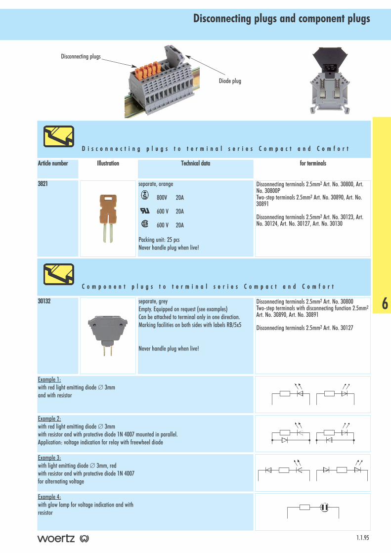
Disconnecting plugs and component plugs
1.1.95
D i s c o n n e c t i n g pp l u g s tt o tt e r m i n a l ss e r i e s CC o m p a c t aa n d CC o m f o r t
for tterminalsTechnical ddataIllustrationArticle nnumber
Disconnecting terminals 2.5mm2 Art. No. 30800, Art.No. 30800PTwo-step terminals 2.5mm2 Art. No. 30890, Art. No.30891
Disconnecting terminals 2.5mm2 Art. No. 30123, Art.No. 30124, Art. No. 30127, Art. No. 30130
separate, orange
800V 20A
600 V 20A
600 V 20A
Packing unit: 25 pcsNever handle plug when live!
3821
Disconnecting terminals 2.5mm2 Art. No. 30800Two-step terminals with disconnecting function 2.5mm2
Art. No. 30890, Art. No. 30891
Disconnecting terminals 2.5mm2 Art. No. 30127
separate, greyEmpty. Equipped on request (see examples)Can be attached to terminal only in one direction.Marking facilities on both sides with labels RB/5x5
Never handle plug when live!
30132
Example 1:with red light emitting diode ∅ 3mmand with resistor
Example 2:with red light emitting diode ∅ 3mmwith resistor and with protective diode 1N 4007 mounted in parallel.Application: voltage indication for relay with freewheel diode
Example 3:with light emitting diode ∅ 3mm, red with resistor and with protective diode 1N 4007for alternating voltage
Example 4:with glow lamp for voltage indication and withresistor
C o m p o n e n t pp l u g s tt o tt e r m i n a l ss e r i e s CC o m p a c t aa n d CC o m f o r t
6
Diode plug
Disconnecting plugs
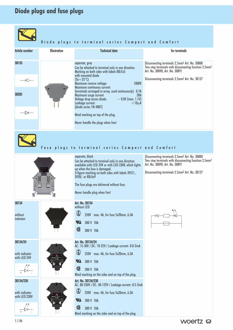
Diode plugs and fuse plugs
1.1.96
D i o d e pp l u g s tt o tt e r m i n a l ss e r i e s CC o m p a c t aa n d CC o m f o r t
for tterminalsTechnical ddataIllustrationArticle nnumber
Disconnecting terminals 2.5mm2 Art. No. 30800Two-step terminals with disconnecting function 2.5mm2
Art. No. 30890, Art. No. 30891
Disconnecting terminals 2.5mm2 Art. No. 30127
separate, greyCan be attached to terminal only in one direction.Marking on both sides with labels RB/5x5with mounted diode(Ta=25°C)Maximum reverse voltage: 1000VMaximum continuous current:(terminals arranged in array, used continuously) 0.7AMaximum surge current 30AVoltage drop across diode: ~ 0.8V (max. 1.1V)Leakage current: <10µA(diode series 1N 4007)
Mind marking on top of the plug.
Never handle the plugs when live!
30133
30205
Disconnecting terminals 2.5mm2 Art. No. 30800Two-step terminals with disconnecting function 2.5mm2
Art. No. 30890, Art. No. 30891
Disconnecting terminals 2.5mm2 Art. No. 30127
separate, blackCan be attached to terminal only in one direction.available with LED 24V or with LED 230V, which lightsup when the fuse is damaged.3-figure marking on both sides with labels 3957/.,3958/. or RB/6x9
The fuse plugs are delivered without fuse.
Never handle plug when live!
Art. NNo. 330134without LED
250V max. 4A, for fuse 5x20mm, 6.3A
300 V 10A
300 V 10A
Art. NNo. 330134/24AC: 15-30V / DC: 10-25V / Leakage current: 0.8-2mA
250V max. 4A, for fuse 5x20mm, 6.3A
300 V 10A
300 V 10AMind marking on the sides and on top of the plug.
Art. NNo. 330134/230AC: 80-250V / DC: 40-125V / Leakage current: 0.5-2mA
250V max. 4A, for fuse 5x20mm, 6.3A
300 V 10A
300 V 10AMind marking on the sides and on top of the plug.
30134
withoutindicator
30134/24
with indicatorwith LED 24V
30134/230
with indicatorwith LED 230V
F u s e pp l u g s tt o tt e r m i n a l ss e r i e s CC o m p a c t aa n d CC o m f o r t
+ -
+ -
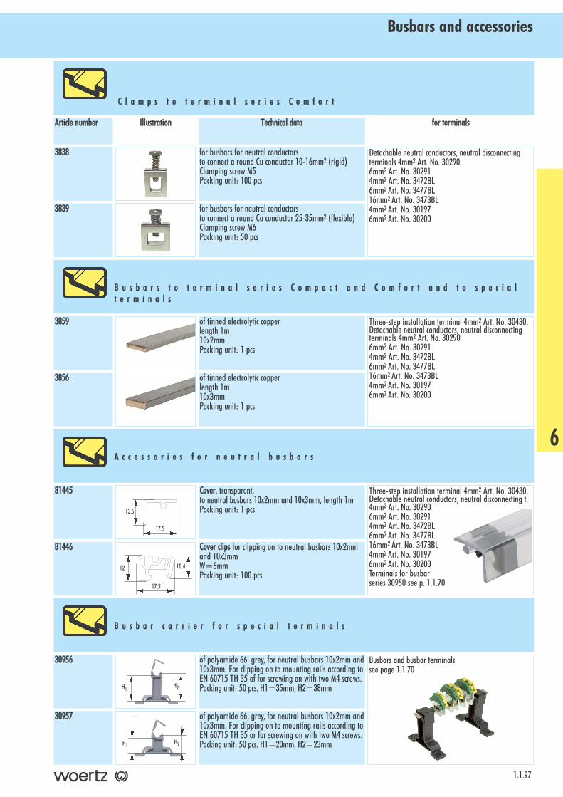
Busbars and accessories
1.1.97
C l a m p s tt o tt e r m i n a l ss e r i e s CC o m f o r t
for tterminalsTechnical ddataIllustrationArticle nnumber
Detachable neutral conductors, neutral disconnectingterminals 4mm2 Art. No. 302906mm2 Art. No. 302914mm2 Art. No. 3472BL6mm2 Art. No. 3477BL16mm2 Art. No. 3473BL4mm2 Art. No. 301976mm2 Art. No. 30200
for busbars for neutral conductorsto connect a round Cu conductor 10-16mm2 (rigid) Clamping screw M5Packing unit: 100 pcs
3838
for busbars for neutral conductorsto connect a round Cu conductor 25-35mm2 (flexible) Clamping screw M6Packing unit: 50 pcs
3839
Three-step installation terminal 4mm2 Art. No. 30430,Detachable neutral conductors, neutral disconnectingterminals 4mm2 Art. No. 302906mm2 Art. No. 302914mm2 Art. No. 3472BL6mm2 Art. No. 3477BL16mm2 Art. No. 3473BL4mm2 Art. No. 301976mm2 Art. No. 30200
of tinned electrolytic copperlength 1m10x3mmPacking unit: 1 pcs
3856
of tinned electrolytic copperlength 1m10x2mmPacking unit: 1 pcs
3859
Busbars and busbar terminalssee page 1.1.70
30956
of polyamide 66, grey, for neutral busbars 10x2mm and10x3mm. For clipping on to mounting rails according toEN 60715 TH 35 or for screwing on with two M4 screws.Packing unit: 50 pcs. H1=20mm, H2=23mm
30957
Three-step installation terminal 4mm2 Art. No. 30430,Detachable neutral conductors, neutral disconnecting t.4mm2 Art. No. 302906mm2 Art. No. 302914mm2 Art. No. 3472BL6mm2 Art. No. 3477BL16mm2 Art. No. 3473BL4mm2 Art. No. 301976mm2 Art. No. 30200Terminals for busbarseries 30950 see p. 1.1.70
Cover, transparent, to neutral busbars 10x2mm and 10x3mm, length 1mPacking unit: 1 pcs
81445
Cover cclips for clipping on to neutral busbars 10x2mmand 10x3mmW=6mmPacking unit: 100 pcs
81446
B u s b a r s tt o tt e r m i n a l ss e r i e s CC o m p a c t aa n d CC o m f o r t aa n d tt o ss p e c i a lt e r m i n a l s
B u s b a r cc a r r i e r ff o r ss p e c i a l tt e r m i n a l s
A c c e s s o r i e s ff o r nn e u t r a l bb u s b a r s
H1 H2
H1 H2
of polyamide 66, grey, for neutral busbars 10x2mm and10x3mm. For clipping on to mounting rails according toEN 60715 TH 35 of for screwing on with two M4 screws.Packing unit: 50 pcs. H1=35mm, H2=38mm
13.5
17.5
12
17.5
10.4
6
Test plugs
1.1.98
T e s t pp l u g s tt o tt e r m i n a l ss e r i e s CC o m p a c t aa n d CC o m f o r t
for tterminalsTechnical ddataIllustrationArticle nnumber
for terminals 3410, 3424, 3425, 3426, 3430, 3430/1P,3450, 3452/6, 3452/10, 30005, 30008, 30128, 30137,30138, 30890, 30891, 30904
Test plug ∅ 2.8mm of silver-plated brass.With hole for strands up to 0.75mm2, protected againstaccidental contact. With red insulation.
Packing unit: 10 pcs
2736R
for terminals 3410, 3424, 3425, 3426, 3430, 3430/1P,3450, 3452/6, 3452/10, 30005, 30008, 30128, 30137,30138, 30890, 30891, 30904
Test plug ∅ 2.8mm of silver-plated brass.With hole for strands up to 0.75mm2, protected againstaccidental contact. With black insulation.
Packing unit: 10 pcs
2736S
for terminals 3410, 3424, 3425, 3426, 3430, 3430/1P,3450, 3452/6, 3452/10, 30005, 30008, 30128, 30137,30138, 30890, 30891, 30904
Test plug ∅ 2.8mm of silver-plated brass. With strand0.75mm2 soldered in and insulated socket for bananaplugs ∅ 4mm, protected against accidental contact.With red insulating sleeve.Packing unit: 10 pcs
2737R
for terminals 3410, 3424, 3425, 3426, 3430, 3430/1P,3450, 3452/6, 3452/10, 30005, 30008, 30128, 30137,30138, 30890, 30891, 30904
Test plug ∅ 2.8mm of silver-plated brass. With strand0.75mm2 soldered in and insulated socket for bananaplugs ∅ 4mm, protected against accidental contact.With black insulating sleeve.Packing unit: 10 pcs
2737S
for terminals 30123, 30130, 30800PTest plug ∅ 2.3mm of silver-plated brass.With hole for strands up to 0.75mm2. With red insula-tion.
Packing unit: 100 pcs
3772PR
for terminals 30123, 30130, 30800PTest plug ∅ 2.3mm of silver-plated brass.With hole for strands up to 0.75mm2. With black insula-tion.
Packing unit: 100 pcs
3772PS
for terminals 3410, 3424, 3425, 3426, 3430, 3430/1P,3450, 3452/6, 3452/10, 30005, 30008, 30128, 30137,30138, 30890, 30891, 30904
Test adaptor (plug+adaptor in one piece), of gold-pla-ted brass, outside ∅ 6mm.For plugging into central thread M3. With socket forbanana plug ∅ 4mm, protected against accidental con-tact. With red insulating sleeve. Packing unit: 10 pcs
80070R
for terminals 3410, 3424, 3425, 3426, 3430, 3430/1P,3450, 3452/6, 3452/10, 30005, 30008, 30128, 30137,30138, 30890, 30891, 30904
Test adaptor (plug+adaptor in one piece), of gold-pla-ted brass, outside ∅ 6mm.For plugging into central thread M3. With socket forbanana plug ∅ 4mm, protected against accidental con-tact. With black insulating sleeve. Packing unit: 10 pcs
80070S
for terminals 3452/16, 3427, 3428Test adaptor (plug+adaptor in one piece), of gold-pla-ted brass, outside ∅ 6mm.For plugging into central thread M4. With socket forbanana plug ∅ 4mm, protected against accidental con-tact. With red insulating sleeve. Packing unit: 10 pcs
80071R
for terminals 3452/16, 3427, 3428Test adaptor (plug+adaptor in one piece), of gold-pla-ted brass, outside ∅ 6mm.For plugging into central thread M4. With socket forbanana plug ∅ 4mm, protected against accidental con-tact. With black insulating sleeve. Packing unit: 10 pcs
80071S
Test plugs
1.1.99
T e s t pp l u g ff o r tt e r m i n a l ss e r i e s CC o m p a c t aa n d CC o m f o r t
for tterminalsTechnical ddataIllustrationArticle nnumber
for two-step terminals 3430Test adaptors for clipping on to two-step-terminal. Measuring fixture with strands for plumbing in the testadaptors.Test adaptors delivered in component parts: with 2 testpins of tinned brass with hole for strands up to0.75mm2, 2 coil springs and 1 insulating body. Procedure: insert coil springs into insulating body frombelow. Push strands from above through coil springs andsolder them in to the test pins. Pull strands with testpins, which are soldered on, upward until the test pinssnap in.Test adaptors can be joined to blocks.Can also be inserted when cross-connection is mounted.Packing unit: 10 pcs
80222/6
for terminals 30150, 30400, 30403, 30430, 30431/1,30431/2, 30810, 30860, 30903, 30973
Test plug ∅ 2.3mm, with contact strips, of gold-platedbrass. With strand 0.5mm2 soldered in and insulatedsocket for banana plug ∅ 4mm, protected against acci-dental contact. With red insulating sleeve.Packing unit: 10 pcs
80247
for terminals 30150, 30400, 30403, 30430, 30431/1,30431/2, 30810, 30860, 30903, 30973
Test plug ∅ 2.3mm, with contact strips, of gold-platedbrass. With strand 0.5mm2 soldered in and insulatedsocket for banana plug ∅ 4mm, protected against acci-dental contact. With black insulating sleeve.Packing unit: 10 pcs
80248
for terminals 30870PTest plug ∅ 2.4mm, of silver-plated brass. With strand0.5mm2 soldered in and insulated socket for bananaplug ∅ 4mm, protected against accidental contact. Withblack insulating sleeve.Packing unit: 100 pcs
80258
for terminals 3450Test adaptors for clipping on to terminal. Measuring fixture with strand for plumbing in the testadaptors.Test adaptors delivered in component parts: With 1 testpin of tinned brass with hole for strands up to0.75mm2, 1 coil spring and 1 insulating body. Procedure: insert coil spring from below into the insula-ting body. Push strand from above through the coilspring and solder it in to the test pin. Pull strand withtest pin, which is soldered on, upward until the test pinsnaps in.Test adaptors can be joined to blocks.Can also be inserted when cross-connection is mounted.
Packing unit: 10 pcs
80220/6
6
Marking strips and marking cards RBE5Marking accessories
1.1.100
Marking sstripsof thermoplastic, white, with 10 labels per strip, printed black. Label size 6 x 3 mm.Available in boxes containing 10 strips with 10 labels each, i.e. 100 labels per box.Labels should not be broken off from marking strip until inserted into the terminal.
label ssize
printing
A
B
C
D
E
F
G
H
I
J
K
L
M
N
O
P
Q
R
S
T
U
V
W
X
Y
Z
1
2
3
4
5
6
7
8
9
0
1-00sequentialnumbering(10x from 1 to 0)
Marking ccards ttype RRBE5For marking 5mm-wide terminals. Made of thermoplastic, white, with 100 labels per card, printedblack. Size of the marking card 122 x 22.1 mm. Label size 5 x 3 mm.Available in boxes containing 5 cards with 100 labels each, i.e. 500 labels per box.
3958/A
3958/B
3958/C
3958/D
3958/E
3958/F
3958/G
3958/H
3958/I
3958/J
3958/K
3958/L
3958/M
6 xx 333958/N
3958/O
3958/P
3958/Q
3958/R
3958/S
3958/T
3958/U
3958/V
3958/W
3958/X
3958/Y
3958/Z
6 xx 333958/1
3958/2
3958/3
3958/4
3958/5
3958/6
3958/7
3958/8
3958/9
3958/0
3958/1-00
6 xx 333958/PE
3958/+
3958/-
3958/AC
3958/DC
3957
3957RO
3957BL
6 xx 33label ssize
printing
label ssize
printing
+
-
~
=
unprinted
white
red
blue
label ssize
printing
label ssize
printing
A
B
C
D
E
F
G
H
I
J
K
L
M
N
O
P
Q
R
S
T
U
V
W
X
Y
Z
A-ZZ ((without OO)
1
2
3
4
5
6
7
8
9
0
1-00sequentialnumbering(10x from 1 to 0)
83010/A
83010/B
83010/C
83010/D
83010/E
83010/F
83010/G
83010/H
83010/I
83010/J
83010/K
83010/L
83010/M
5 xx 3383010/N
83010/O
83010/P
83010/Q
83010/R
83010/S
83010/T
83010/U
83010/V
83010/W
83010/X
83010/Y
83010/Z
83010/A-ZZ
5 xx 3383010/1
83010/2
83010/3
83010/4
83010/5
83010/6
83010/7
83010/8
83010/9
83010/0
83010/1-00
5 xx 3383010/PE
83010/+
83010/-
83010/AC
83010/DC
83010
5 xx 33label ssize
printing
label ssize
printing
+
-
~
=
unprintedwhite
label ssize
printing

Marking cards type RBMarking accessories
1.1.101
For marking of 5, 6 or 8mm-wide terminals. Marking cards of polyamide 66, white, with 100 labelsper card, printed black (see table below). Label size: 5 x 5 mm, 5 x 9 mm, 5 x 12 mm, 6 x 9 mm, 6 x 12 mm, 8 x 9 mm or 8 x 12 mm.Available in boxes containing 5 cards with 100 labels each, i.e. 500 labels per box.
Woertz Service: marking on request (see order form page 1.1.103).Individual terminal marking with Winscript (see page 1.1.104).
5 xx 55 5 xx 99 5 xx 112 6 xx 99 6 xx 112 8 xx 99 8 xx 112label ssizeprinting
1-110
11-220
21-330
31-440
41-550
51-660
61-770
71-880
81-990
91-1100
35455/5501
35455/5502
35455/5503
35455/5504
35455/5505
35455/5506
35455/5507
35455/5508
35455/5509
35455/5510
35455/5901
35455/5902
35455/5903
35455/5904
35455/5905
35455/5906
35455/5907
35455/5908
35455/5909
35455/5910
35455/5201
35455/5202
35455/5203
35455/5204
35455/5205
35455/5206
35455/5207
35455/5208
35455/5209
35455/5210
35455/6901
35455/6902
35455/6903
35455/6904
35455/6905
35455/6906
35455/6907
35455/6908
35455/6909
35455/6910
35455/6201
35455/6202
35455/6203
35455/6204
35455/6205
35455/6206
35455/6207
35455/6208
35455/6209
35455/6210
35455/8901
35455/8902
35455/8903
35455/8904
35455/8905
35455/8906
35455/8907
35455/8908
35455/8909
35455/8910
35455/8201
35455/8202
35455/8203
35455/8204
35455/8205
35455/8206
35455/8207
35455/8208
35455/8209
35455/8210
1-550
51-1100
101-1150
151-2200
201-3300
301-4400
401-5500
1-5500
35455/5511
35455/5512
35455/5513
35455/5514
35455/5515
35455/5516
35455/5517
35455/5518
35455/5911
35455/5912
35455/5913
35455/5914
35455/5915
35455/5916
35455/5917
35455/5918
35455/5211
35455/5212
35455/5213
35455/5214
35455/5215
35455/5216
35455/5217
35455/5218
35455/6911
35455/6912
35455/6913
35455/6914
35455/6915
35455/6916
35455/6917
35455/6918
35455/6211
35455/6212
35455/6213
35455/6214
35455/6215
35455/6216
35455/6217
35455/6218
35455/8911
35455/8912
35455/8913
35455/8914
35455/8915
35455/8916
35455/8917
35455/8918
35455/8211
35455/8212
35455/8213
35455/8214
35455/8215
35455/8216
35455/8217
35455/8218
L1
L2
L3
L1L2L3 (( oon 11 llabel)
L1 LL2 LL3 ((32 ttimes)
N
+
-
35455/5530
35455/5531
35455/5532
35455/5533
35455/5534
35455/5535
35455/5536
35455/5537
35455/5538
35455/5930
35455/5931
35455/5932
35455/5933
35455/5934
35455/5935
35455/5936
35455/5937
35455/5938
35455/5230
35455/5231
35455/5232
35455/5233
35455/5234
35455/5235
35455/5236
35455/5237
35455/5238
35455/6930
35455/6931
35455/6932
35455/6933
35455/6934
35455/6935
35455/6936
35455/6937
35455/6938
35455/6230
35455/6231
35455/6232
35455/6233
35455/6234
35455/6235
35455/6236
35455/6237
35455/6238
35455/8930
35455/8931
35455/8932
35455/8933
35455/8934
35455/8935
35455/8936
35455/8937
35455/8938
35455/8230
35455/8231
35455/8232
35455/8233
35455/8234
35455/8235
35455/8236
35455/8237
35455/8238
A-ZZ(without OO)
35455/5540 35455/5940 35455/5240 35455/6940 35455/6240 35455/8940 35455/8240
unprinted 35455/05X05 35455/05X09 35455/05X12 35455/06X09 35455/06X12 35455/08X09 35455/08X12
6

Label holders and cases for marking accessories
Marking accessories
1.1.102
Technical ddataIllustrationArticle nnumber
of polyamide 6, flexible, blackfor cables 3x1.5mm2 and moreconsisting of 5 holders molded together for 4 labels each, 3x6mm 3957/..., 3958/...fastening with cable straps Divisible by means of any cutting tool Cable straps have to be ordered separately.
Packing unit: 50 pcs
3954
for terminals 30902, 30904, 3430, 30430, 30431,30432, 30890, 30891
Label carriers for larger markingsof polyamide 66, greyfor clipping on 6mm-wide terminals with 3-figure mar-king only
for 4 labels 3x6mm 3957/..., 3958/..Packing unit: 100 pcs
3955/4
Label carriers for larger markingsof polyamide 66, greyfor clipping on 6mm-wide terminals with 3-figure mar-king only
for 6 labels 3x6mm 3957/..., 3958/..Packing unit: 100 pcs
3955/6
H o l d e r ff o r mm a r k i n g cc a b l e s
L a b e l cc a r r i e r s
C a s e ff o r mm a r k i n g aa c c e s s o r i e s ww i t h ii n s e r t s ff o r mm a r k i n g ss t r i p s oo rm a r k i n g cc a r d s
Case ffor mmarking aaccessories of plastic, blue, resistant to shocks, stackableFor receiving 2 transparent inserts for marking strips or marking cardsExternal dimensions 400x300x80mmempty, without inserts
80155
Insert ffor mmarking sstripsExternal dimensions 360x260x30mm- with 12 parts for marking strips type 3957/..., 3958/..
80156
Insert ffor mmarking ccardsExternal dimensions 360x260x30mm- with 3 parts for marking cards- with 3 parts for marking strips type 3957/..., 3958/..
80158
Marking cards printed according to your choice
Marking accessories
1.1.103
Please fill out the form with block letters and order by fax. FFaaxx SSwwiittzzeerrllaanndd:: ++4411 ((00))6611 446611 9966 0066Make sure you have ticked the label type you want. FFaaxx UUSSAA:: ((880000)) 552222-33886688
BBiilllliinngg aaddddrreessss::(if different from shipping address)
Company: . . . . . . . . . . . . . . . . . . . . . . . . . . . . . . . . . . . . . . . . . . . . . . . . . . . . . . .
Address: . . . . . . . . . . . . . . . . . . . . . . . . . . . . . . . . . . . . . . . . . . . . . . . . . . . . . . . .
ZIP code/city: . . . . . . . . . . . . . . . . . . . . . . . . . . . . . . . . . . . . . . . . . . . . . . . . . . . .
Tel.: . . . . . . . . . . . . . . . . . . . . . . . . . . . . . . . . . . . . . . . . . . . . . . . . . . . . . . . . . . . .
Fax: . . . . . . . . . . . . . . . . . . . . . . . . . . . . . . . . . . . . . . . . . . . . . . . . . . . . . . . . . . . .
Contact person: . . . . . . . . . . . . . . . . . . . . . . . . . . . . . . . . . . . . . . . . . . . . . . . . . . .
AA dd rr ee ss ss ee
SShhiippppiinngg aaddddrreessss::Customer number:. . . . . . . . . . . . . . . . . . . . . . . . . . . . . . . . . . . . . . . . . . . . . . . . .
Company: . . . . . . . . . . . . . . . . . . . . . . . . . . . . . . . . . . . . . . . . . . . . . . . . . . . . . . .
Address: . . . . . . . . . . . . . . . . . . . . . . . . . . . . . . . . . . . . . . . . . . . . . . . . . . . . . . . .
ZIP code/city: . . . . . . . . . . . . . . . . . . . . . . . . . . . . . . . . . . . . . . . . . . . . . . . . . . . .
Tel.: . . . . . . . . . . . . . . . . . . . . . . . . . . . . . . . . . . . . . . . . . . . . . . . . . . . . . . . . . . . .
Fax: . . . . . . . . . . . . . . . . . . . . . . . . . . . . . . . . . . . . . . . . . . . . . . . . . . . . . . . . . . . .
Contact person: . . . . . . . . . . . . . . . . . . . . . . . . . . . . . . . . . . . . . . . . . . . . . . . . . . .
llaabbeell ttyyppee pprriinnttiinngg mmaaxx..
5 6
4 7
3 8
2 9
1 10
OO rr dd ee rr
aarrttiiccllee nnuummbbeerr llaabbeell ssiizzee
RB/5x5 3-figure vertically / 3-figure horizontally
AAvvaaiillaabbllee ssppeecciiaall cchhaarraacctteerrssSpecial characters count as 2 figures!
35455/05S05 5 x 5 mm
RB/5x9 6-figure vertically / 3-figure horizontally35455/05S09 5 x 9 mm
RB/5x12 9-figure vertically / 3-figure horizontally35455/05S12 5 x 12 mm
RB/6x9 6-figure vertically / 4-figure horizontally35455/06S09 6 x 9 mm
RB/6x12 9-figure vertically / 4-figure horizontally35455/06S12 6 x 12 mm
RB/8x9 6-figure vertically / 6-figure horizontally35455/08S09 8 x 9 mm
RB/8x12 9-figure vertically / 6-figure horizontally35455/08S12 8 x 12 mm
PP rr ii nn tt ii nn gg
≈ ∼
Ω
∼ ...2 ...3
We order .................... card(s) of the selected type with printing according to drawing below.
PP rr ii nn tt ii nn gg ee xx aa mm pp ll ee
1 L1 L2 L3 150
250
350 Ω A-
10
6
Winscript System - Individual terminal marking systemMarking accessories
1.1.104
Designation // Technical ddataArticle nnumber Designation // Technical ddataArticle nnumber
Software including user manual5 languages D, F, I, E, S
80515
Plotter including user manual and communication cablePC-Plotter
80323
Base pplates Woertz including 2x6 spacers to receive 6Woertz marker cards
80500
Base pplates WWoertzto receive Woertz marking strips series 35455/..BS
80500BS
W i n s c r i p t SS y s t e m
Plotter ppen with pen point80514
Ink80507
Disposable iink ppens HHPC (4 pieces) for paper labels80510
Spacers to Woertz base plates for marker cards type5x9/6x9/6x12/8x9/8x12 mm
80501
Cleaning ssolution to ink80519 Spacers to Woertz base plates for marker cards type 5x5 mm
80502
Cleaning sset80518 Base pplate for marking paper labels etc. of powder-coated steel including magnetic pins and stripsfor holding the paper sheet
80506
A c c e s s o r i e s
Adels bbase pplate to receive Adels marker cards80505AD
Entrelec bbase pplate to receive Entrelec marker cardsRC55/RC65/RC510/RC610/RC810
80505ENT
Télémécanique bbase pplate to receive Télémécanique marker cards
80505TE
Wago bbase pplate to receive Wago marker cards, including1 interchangeable locating device for WSB 5-8mm andone for WSB 4mm
80505WA
Phoenix bbase pplate to receive Phoenix marker cards, inclu-ding. 2 magazine inserts for 14 Zack marker strips CMS-U/ZB
80505PHX Weidmüller bbase pplate to receive Weidmüller markingcards
80505WDM
SES bbase pplate to receive SES marker cards, labels type14-1177 (cable marking)
80505SES Wieland bbase pplates to receive Wieland marker cards5x8.3/5x14/6x8.3/6x14/8x8.3
80505WI
A c c e s s o r i e s ff o r mm a r k i n g cc o m p e t i t o r ll a b e l s
Art. No. 80323
Art. No. 80501
Art. No. 80500
Art. No. 80502
Art. No. 80506 Art. No. 80507Art. No. 80510
Art. No. 80514 Art. No. 80519
≈ ∼
Ω
∼
2 3
Available ssymbols:

Rails and accessories
1.1.105
M o u n t i n g rr a i l s aa c c o r d i n g tt o EE N 66 0 7 1 5 T H 3 5
Technical ddataIllustrationArticle nnumber
Galvanized steela=35mm, b=7.3mm, c=27mm, d=1mmCorresponds to the thermal resistance to short-circuitsof a Cu conductor of 16mm2
Made in lengths of 2m, weight 325 g/m
3401
Galvanized boored steel, 18 x 5.2 mma=35mm, b=7.3mm, c=27mm, d=1mmCorresponds to the thermal resistance to short-circuitsof a Cu conductor of 16mm2
Made in lengths of 2m, weight 310 g/m
3401/L
Stainless steel A2a=35mm, b=7.3mm, c=27mm, d=1mmCorresponds to the thermal resistance to short-circuitsof a Cu conductor of 16mm2
Made in lengths of 2m, weight 365 g/m
3401IN
Galvanized steela=35mm, b=15mm, c=24mm, d=1mm, d1=2.5mmCorresponds to the thermal resistance to short-circuitsof a Cu conductor of 50mm2
Made in lengths of 2m, weight 925 g/m
3490
Galvanized boored steel, 18 x 5.2 mma=35mm, b=15mm, c=24mm, d=1mm, d1=2.5mmCorresponds to the thermal resistance to short-circuitsof a Cu conductor of 50mm2
Made in lengths of 2m, weight 890 g/m
3490/L
coppera=35mm, b=15mm, c=24mm, d=1mm, d1=2.3mmCorresponds to the thermal resistance to short-circuitsof a Cu conductor of 150mm2
Made in lengths of 2m, weight 765 g/m
80290
external profile flanks according to EN 60715TH35,internal profile flanks according to EN 60715TH15aluminum alloy, Extrudal-050a=35mm, b=7.3mm, c=27mm, d=1mm, e=15mmCorresponds to the thermal resistance to short-circuitsof a Cu conductor of 35mm2
Made in lengths of 2m, weight 260 g/m
3400A
external profile flanks according to EN 60715TH35,internal profile for receiving Woertz anchoring studsseries 4420 and Woertz cable fixing brackets series 4350.aluminum alloy, Extrudal-050a=35mm, b=15mm, c=35mm, d=1mm,d1=1.8mm, e=16.7mmCorresponds to the thermal resistance to short-circuitsof a Cu conductor of 85mm2
80291/2MMade in lengths of 2m, weight 379 g/m80291/3MMade in lengths of 3m, weight 379 g/m80291/6MMade in lengths of 6m, weight 379 g/m
80291/2M
80291/3M
80291/6M
Dimension iillustration
C o m b i n e d rr a i l s
a
c
b
d
a
c
b
d
d1
a
e
c
b
d
a
e
d1
c
b
d
6
25
18
5.2
Rails and accessories
1.1.106
C a b l e - ff a s t e n e r s ff o r cc l i p p i n g
Technical ddataIllustrationArticle nnumber
for clipping on to rails according toEN 60715TH35of polyamide 66, grey For use in switchboards.Delivered without cable straps.Any cable straps may be used with these fasteners.
80063 80065for cables ∅ 6-9mm for cables ∅ 12-16mmB=10mm B=18mmPacking unit: 100 pcs Packing unit: 25 pcs
80064 80066for cables ∅ 9-12mm for cables ∅ 16-20mmB=14mm B=22mmPacking unit: 100 pcs Packing unit: 25 pcs
Dimension iillustration
80063
80064
80065
80066
for clipping on to mounting rails according to EN60715TH35, of polyamide 66, greymay be used for mounting devices, with 3 borings forcylinder head self-tapping screw ∅ 3.5mmPacking unit: 100 pcs
9072
for clipping on to mounting rails according to EN60715TH35, of polyamide 66, greymay be used for mounting devices extending beyond theclamp, with 3 borings for cylinder head self-tappingscrew ∅ 3.5mm. Packing unit: 100 pcs
49907
Base part of brass, stud of steelfor mounting rails according to EN 60715TH35with bolt thread and sealing screw M3 Clamping couple for electric screw-driver 0.8 Nm.Width = 6mm
Packing unit: 50 pcs
80059/31
80059/38
80059/45
80059/55
80059/65
80059/75
H mm 31
H mm 38
H mm 45
H mm 55
H mm 65
H mm 75
C l a m p s ff o r cc l i p p i n g
S u p p o r t i n g ss t u d s ff o r cc o v e r s
To terminal covers Art. No. 80079/10, 80079/35,80079/120 see page 1.1.92
H
Rails and accessories
1.1.107
L a b e l cc a r r i e r ff o r gg r o u p mm a r k i n g
Technical ddataIllustrationArticle nnumber
of polyamide 66, grey, halogen-freeto mounting rails according to EN 60715TH35with label 10x37mm of PVC, white
Under the label 10x37mm the label carrier for groupmarking has a boring for screwing on any other mar-king label or marking strip with a cylinder head self-tapping screw ∅ 2.9x9.5mm
Packing unit: 100 pcs
Dimension iillustration
3459
A n g l e d ss u p p o r t bb r a c k e t
of sheet steel 2 mm, galvanizedLength 89mm, width 20 mm, height 48mmangle of 30°with screw thread M6for an accessible arrangement of terminals
Packing unit: 10 pcs
80360/30
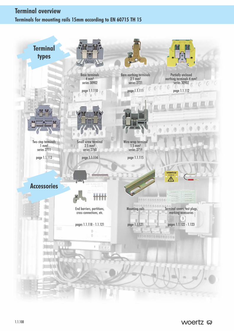
Terminals for mounting rails 15mm according to EN 60715 TH 15Terminal overview
1.1.108
Partially enclosedearthing terminals 4 mm2
series 30902
page 1.1.112
Basic terminals 4 mm2
series 30902
page 1.1.110
Wire-wrap terminal 1.5 mm2
series 2759
page 1.1.115
Two-step terminals1 mm2
series 2711
page 1.1.113
Small screw terminal 2.5 mm2
series 2760
page 1.1.114
Terminal covers, test plugs,marking accessories
pages 1.1.122 - 1.123
Terminaltypes
Bare earthing terminals 2.5 mm2
series 2721
page 1.1.111
Accessories
End barriers, partitions,cross-connections, etc.
pages 1.1.118 - 1.1.121
Mounting rails
page 1.1.121
T e r m i n a l ss e r i e s p a g e s 11 . 1 . 1 0 9 tt o 11 . 1 . 1 1 5B a s i c t e r m i n a l s 4 m m 2 . . . . . . . . . . . . . . . . . . . . . . . 1 . 1 . 1 1 0B a r e e a r t h i n g t e r m i n a l 2 . 5 m m 2 . . . . . . . . . . . . . . . . . . 1 . 1 . 1 1 1P a r t i a l l y e n c l o s e d e a r t h i n g t e r m i n a l 4 m m 2 . . . . . . . . . . 1 . 1 . 1 1 2T w o - s t e p t e r m i n a l 1 m m 2 . . . . . . . . . . . . . . . . . . . . . . 1 . 1 . 1 1 3S m a l l s c r e w t e r m i n a l 2 . 5 m m 2 . . . . . . . . . . . . . . . . . . . 1 . 1 . 1 1 4W i r e - w r a p t e r m i n a l 1 . 5 m m 2 . . . . . . . . . . . . . . . . . . . . 1 . 1 . 1 1 5
1.1.109
IndexTerminals for mounting rails 15mm according to EN 60715 TH 15
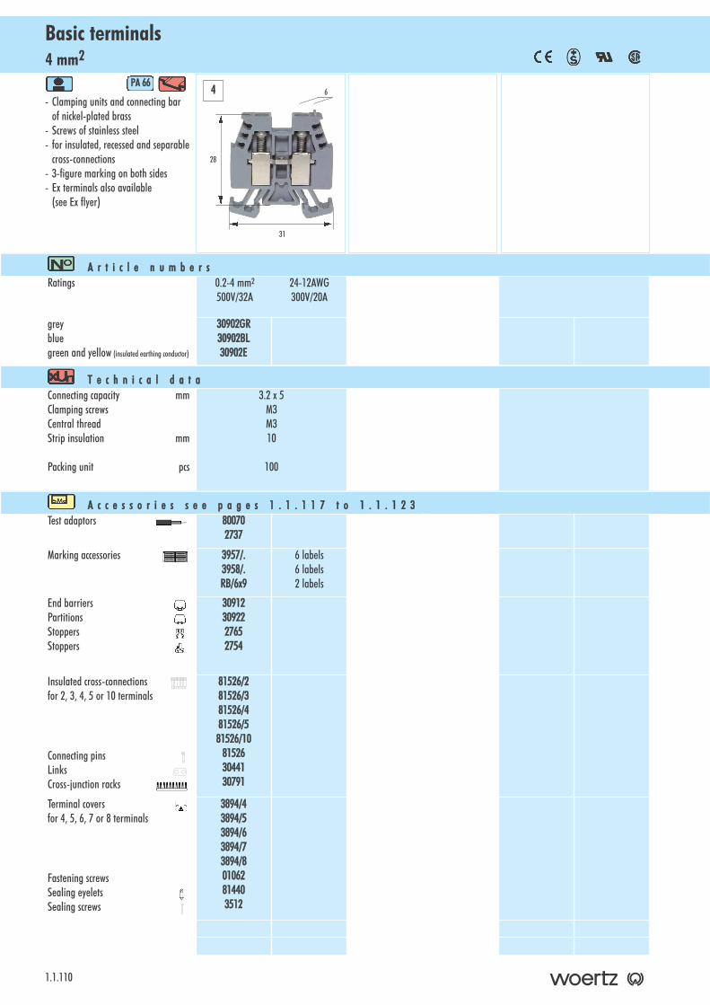
4 mm2Basic terminals
1.1.110
- Clamping units and connecting barof nickel-plated brass
- Screws of stainless steel- for insulated, recessed and separable
cross-connections- 3-figure marking on both sides - Ex terminals also available
(see Ex flyer)
PA 666
A r t i c l e nn u m b e r sRatings 0.2-4 mm2 24-12AWG
500V/32A 300V/20A
greybluegreen and yellow (insulated earthing conductor)
30902GR30902BL30902E
T e c h n i c a l dd a t aConnecting capacity mmClamping screwsCentral threadStrip insulation mm
Packing unit pcs
3.2 x 5M3M310
100
A c c e s s o r i e s ss e e pp a g e s 11 . 1 . 1 1 7 tt o 11 . 1 . 1 2 3Test adaptors 80070
2737
Marking accessories 3957/.3958/.RB/6x9
6 labels6 labels2 labels
End barriersPartitionsStoppersStoppers
309123092227652754
Insulated cross-connectionsfor 2, 3, 4, 5 or 10 terminals
Connecting pinsLinks Cross-junction racks
81526/281526/381526/481526/581526/10
815263044130791
Terminal covers for 4, 5, 6, 7 or 8 terminals
Fastening screws Sealing eyelets Sealing screws
3894/43894/53894/63894/73894/801062814403512
28
31
64
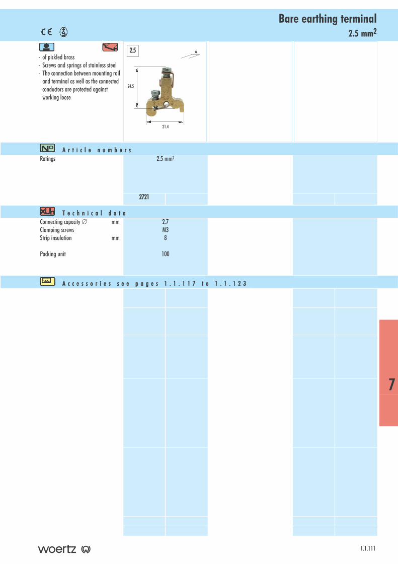
2.5 mm2Bare earthing terminal
- of pickled brass- Screws and springs of stainless steel- The connection between mounting rail
and terminal as well as the connected conductors are protected against working loose
1.1.111
A r t i c l e nn u m b e r sRatings 2.5 mm2
2721
T e c h n i c a l dd a t aConnecting capacity ∅ mmClamping screwsStrip insulation mm
Packing unit
2.7M38
100
A c c e s s o r i e s ss e e pp a g e s 11 . 1 . 1 1 7 tt o 11 . 1 . 1 2 3
24.5
21.4
62.5
7
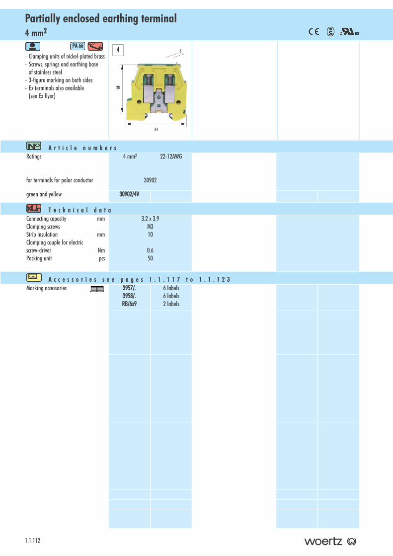
4 mm2Partially enclosed earthing terminal
1.1.112
- Clamping units of nickel-plated brass - Screws, springs and earthing base
of stainless steel- 3-figure marking on both sides- Ex terminals also available
(see Ex flyer)
PA 666
A r t i c l e nn u m b e r sRatings
for terminals for polar conductor
4 mm2 22-12AWG
30902
green and yellow 30902/4V
T e c h n i c a l dd a t aConnecting capacity mmClamping screwsStrip insulation mmClamping couple for electric screw-driver NmPacking unit pcs
3.2 x 3.9M310
0.650
A c c e s s o r i e s ss e e pp a g e s 11 . 1 . 1 1 7 tt o 11 . 1 . 1 2 3Marking accessories 3957/.
3958/.RB/6x9
6 labels6 labels2 labels
4
28
34
6
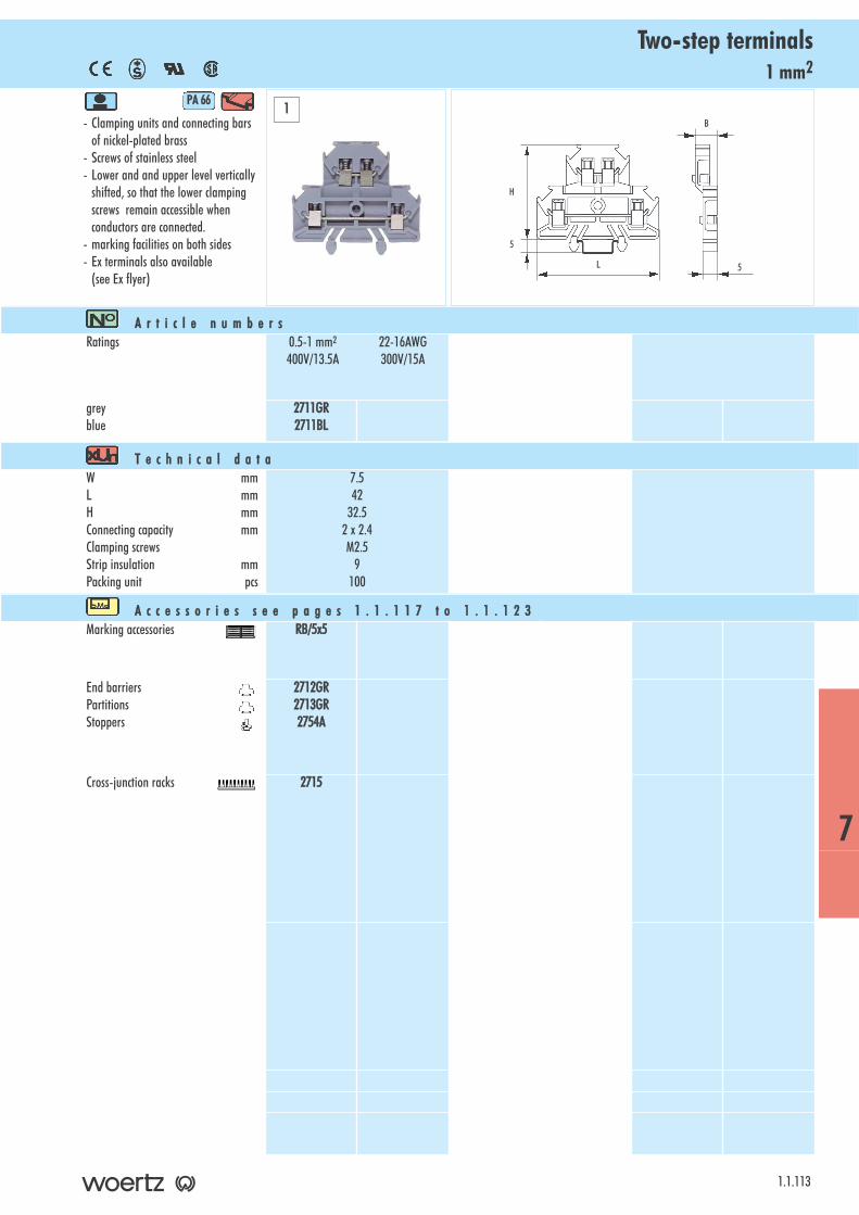
1 mm2Two-step terminals
- Clamping units and connecting barsof nickel-plated brass
- Screws of stainless steel- Lower and and upper level vertically
shifted, so that the lower clampingscrews remain accessible whenconductors are connected.
- marking facilities on both sides - Ex terminals also available
(see Ex flyer)
PA 666
1.1.113
A r t i c l e nn u m b e r sRatings 0.5-1 mm2 22-16AWG
400V/13.5A 300V/15A
greyblue
2711GR2711BL
T e c h n i c a l dd a t aW mmL mmH mmConnecting capacity mmClamping screwsStrip insulation mmPacking unit pcs
7.542
32.52 x 2.4M2.5
9100
A c c e s s o r i e s ss e e pp a g e s 11 . 1 . 1 1 7 tt o 11 . 1 . 1 2 3Marking accessories RB/5x5
End barriersPartitionsStoppers
2712GR2713GR2754A
Cross-junction racks 2715
1
7
H
L
5
B
5
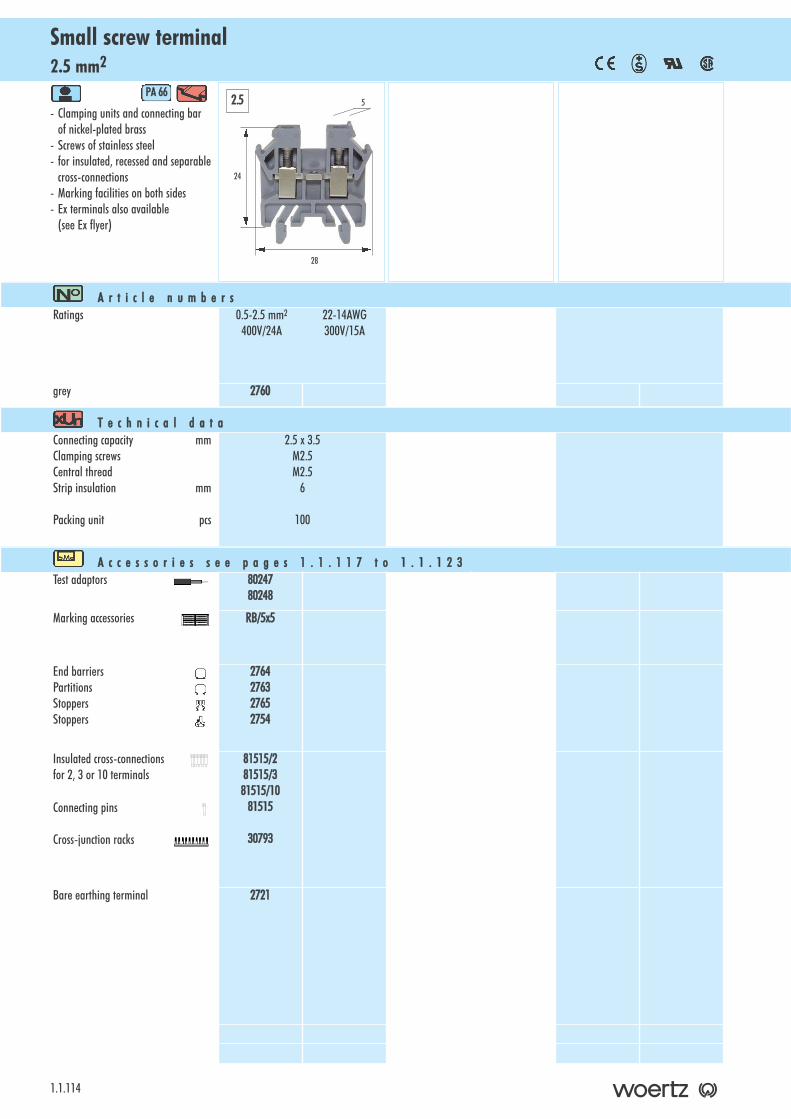
2.5 mm2Small screw terminal
1.1.114
- Clamping units and connecting barof nickel-plated brass
- Screws of stainless steel- for insulated, recessed and separable
cross-connections- Marking facilities on both sides- Ex terminals also available
(see Ex flyer)
PA 666
A r t i c l e nn u m b e r sRatings 0.5-2.5 mm2 22-14AWG
400V/24A 300V/15A
grey 2760
T e c h n i c a l dd a t aConnecting capacity mmClamping screwsCentral threadStrip insulation mm
Packing unit pcs
2.5 x 3.5M2.5M2.5
6
100
A c c e s s o r i e s ss e e pp a g e s 11 . 1 . 1 1 7 tt o 11 . 1 . 1 2 3Test adaptors 80247
80248
Marking accessories RB/5x5
End barriersPartitionsStoppersStoppers
2764276327652754
Insulated cross-connectionsfor 2, 3 or 10 terminals
Connecting pins
Cross-junction racks
81515/281515/381515/10
81515
30793
Bare earthing terminal 2721
24
28
52.5
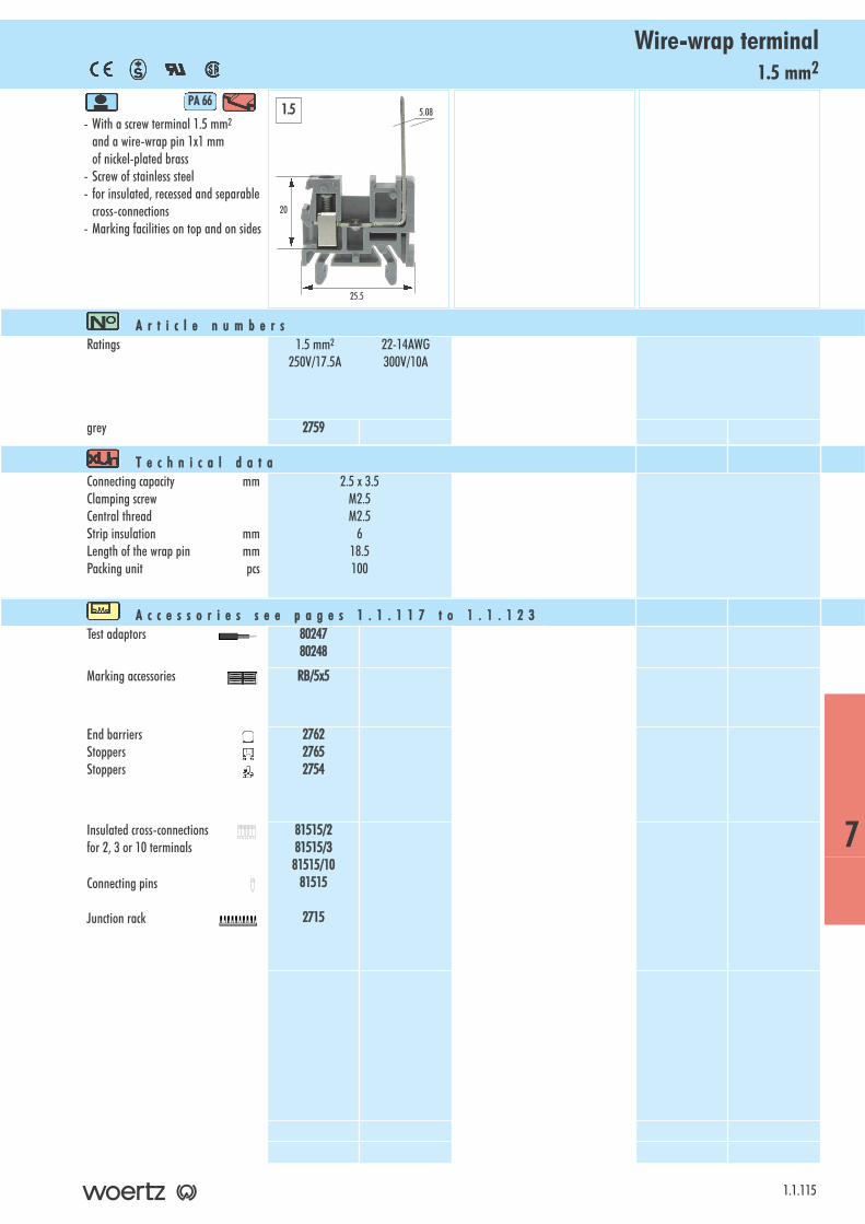
1.5 mm2Wire-wrap terminal
- With a screw terminal 1.5 mm2
and a wire-wrap pin 1x1 mm of nickel-plated brass
- Screw of stainless steel- for insulated, recessed and separable
cross-connections- Marking facilities on top and on sides
PA 666
1.1.115
A r t i c l e nn u m b e r sRatings 1.5 mm2 22-14AWG
250V/17.5A 300V/10A
grey 2759
T e c h n i c a l dd a t aConnecting capacity mmClamping screwCentral threadStrip insulation mmLength of the wrap pin mmPacking unit pcs
2.5 x 3.5M2.5M2.5
618.5100
A c c e s s o r i e s ss e e pp a g e s 11 . 1 . 1 1 7 tt o 11 . 1 . 1 2 3Test adaptors 80247
80248
Marking accessories RB/5x5
End barriersStoppersStoppers
276227652754
Insulated cross-connectionsfor 2, 3 or 10 terminals
Connecting pins
Junction rack
81515/281515/381515/10
81515
2715
20
25.5
5.081.5
7

Notes
1.1.116
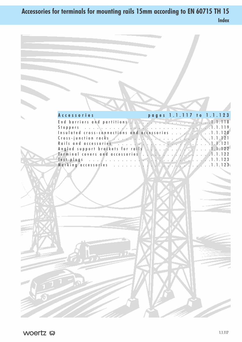
A c c e s s o r i e s p a g e s 11 . 1 . 1 1 7 tt o 11 . 1 . 1 2 3E n d b a r r i e r s a n d p a r t i t i o n s . . . . . . . . . . . . . . . . . . . . 1 . 1 . 1 1 8S t o p p e r s . . . . . . . . . . . . . . . . . . . . . . . . . . . . . . . 1 . 1 . 1 1 9I n s u l a t e d c r o s s - c o n n e c t i o n s a n d a c c e s s o r i e s . . . . . . . . . . 1 . 1 . 1 2 0C r o s s - j u n c t i o n r a c k s . . . . . . . . . . . . . . . . . . . . . . . . 1 . 1 . 1 2 1R a i l s a n d a c c e s s o r i e s . . . . . . . . . . . . . . . . . . . . . . . 1 . 1 . 1 2 1A n g l e d s u p p o r t b r a c k e t s f o r r a i l s . . . . . . . . . . . . . . . . 1 . 1 . 1 2 2T e r m i n a l c o v e r s a n d a c c e s s o r i e s . . . . . . . . . . . . . . . . . 1 . 1 . 1 2 2T e s t p l u g s . . . . . . . . . . . . . . . . . . . . . . . . . . . . . . 1 . 1 . 1 2 3M a r k i n g a c c e s s o r i e s . . . . . . . . . . . . . . . . . . . . . . . . 1 . 1 . 1 2 3
1.1.117
Index Accessories for terminals for mounting rails 15mm according to EN 60715 TH 15
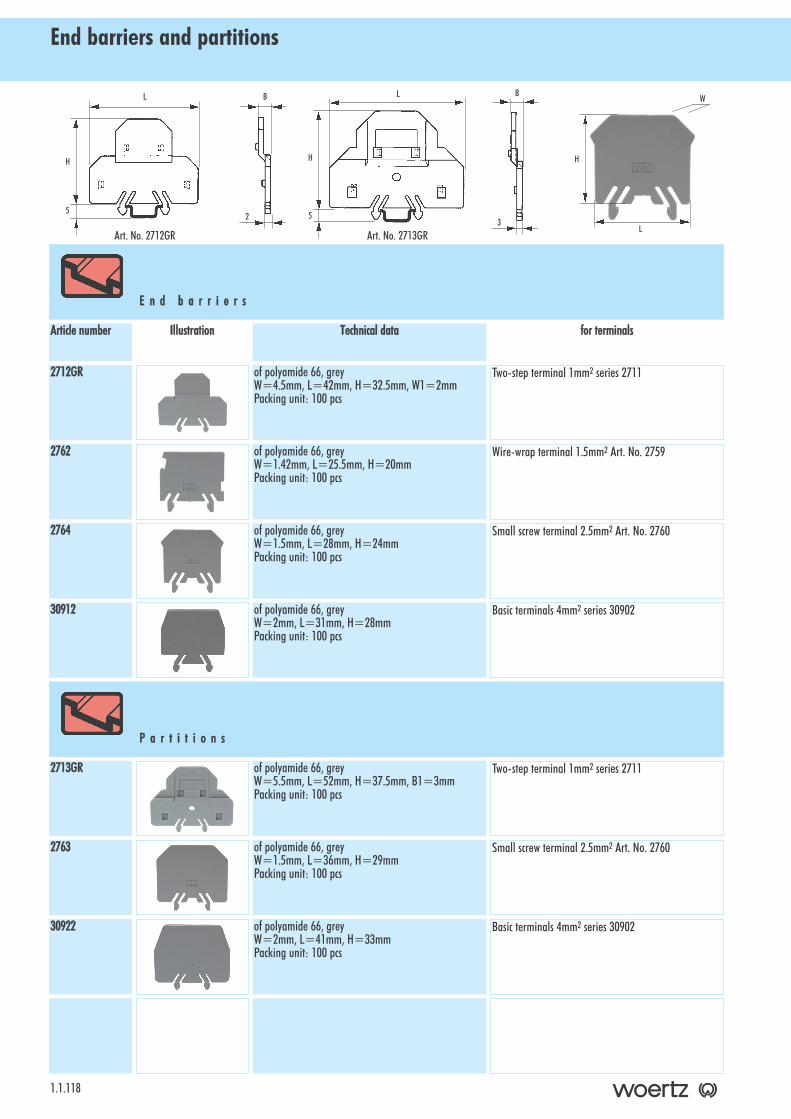
End barriers and partitions
1.1.118
E n d bb a r r i e r s
for tterminalsTechnical ddataIllustrationArticle nnumber
Two-step terminal 1mm2 series 2711of polyamide 66, greyW=4.5mm, L=42mm, H=32.5mm, W1=2mmPacking unit: 100 pcs
2712GR
Wire-wrap terminal 1.5mm2 Art. No. 2759of polyamide 66, greyW=1.42mm, L=25.5mm, H=20mmPacking unit: 100 pcs
2762
Small screw terminal 2.5mm2 Art. No. 2760of polyamide 66, greyW=1.5mm, L=28mm, H=24mmPacking unit: 100 pcs
2764
Basic terminals 4mm2 series 30902of polyamide 66, greyW=2mm, L=31mm, H=28mmPacking unit: 100 pcs
30912
Two-step terminal 1mm2 series 2711of polyamide 66, greyW=5.5mm, L=52mm, H=37.5mm, B1=3mmPacking unit: 100 pcs
2713GR
Small screw terminal 2.5mm2 Art. No. 2760of polyamide 66, greyW=1.5mm, L=36mm, H=29mmPacking unit: 100 pcs
2763
Basic terminals 4mm2 series 30902of polyamide 66, greyW=2mm, L=41mm, H=33mmPacking unit: 100 pcs
30922
H
L
W
P a r t i t i o n s
H
L
52
B
H
L
53
B
Art. No. 2712GR Art. No. 2713GR
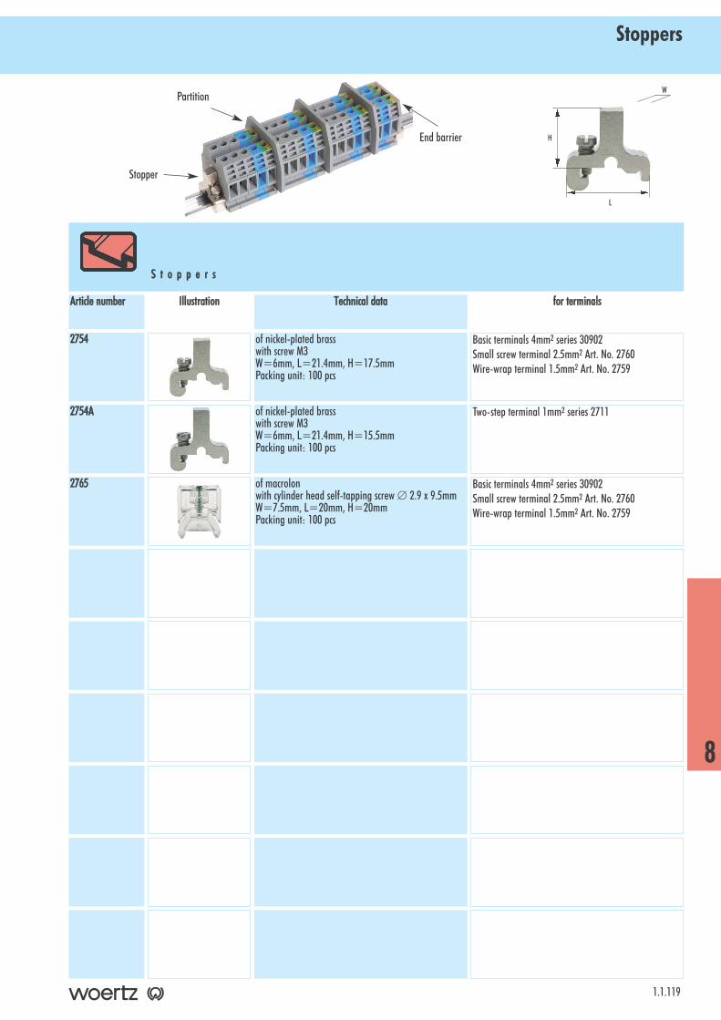
Stoppers
1.1.119
S t o p p e r s
for tterminalsTechnical ddataIllustrationArticle nnumber
Basic terminals 4mm2 series 30902Small screw terminal 2.5mm2 Art. No. 2760Wire-wrap terminal 1.5mm2 Art. No. 2759
of nickel-plated brasswith screw M3W=6mm, L=21.4mm, H=17.5mmPacking unit: 100 pcs
2754
Two-step terminal 1mm2 series 2711of nickel-plated brasswith screw M3W=6mm, L=21.4mm, H=15.5mmPacking unit: 100 pcs
2754A
Basic terminals 4mm2 series 30902Small screw terminal 2.5mm2 Art. No. 2760Wire-wrap terminal 1.5mm2 Art. No. 2759
of macrolonwith cylinder head self-tapping screw ∅ 2.9 x 9.5mmW=7.5mm, L=20mm, H=20mmPacking unit: 100 pcs
2765
H
L
W
8
End barrier
Stopper
Partition

Insulated cross-connections and accessories
1.1.120
To be screwed in connecting bars. Cross-connections are used tojumper adjacent terminals. They are of nickel-plated brass.Complete cross-connections are available with connecting pins,screws, washers and spacer sleeves. They are protected againstaccidental contact with insulated screw heads. Standard separa-ble versions: 2-, 3-, 4-, 5- and 10-part.
I n s u l a t e d cc r o s s - cc o n n e c t i o n s
for tterminalsTechnical ddataDescriptionIllustration
Article nnumber
Small screw terminal 2.5mm2 Art. No. 2760Wire-wrap terminal 1.5mm2 Art. No. 2759
6mm wide1mm thickHole ∅ =3mm10-part: L=50mmPacking unit: 10 pcs
81515/2
81515/3
81515/10
of nickel-plated brasswith screw with insulated head, washer and spacersleeveSpacer sleeve: length=5.5mm, outside ∅ =4mmScrew M2.5x9.5Packing unit: 100 pcs
81515
Cross-cconnections
2-part
3-part
10-part
Separate cconnecting ppin
Basic terminal 4mm2 Art. No. 309026mm wide1mm thickHole ∅ =3.5mm10-part: L=60mmPacking unit: 10 pcs
81526/2
81526/3
81526/4
81526/5
81526/10
of nickel-plated brasswith screw with insulated head, washer and spacersleeveSpacer sleeve: length=10.5mm, outside ∅ =4mmScrew M3x17Packing unit: 100 pcs
81526
of nickel-plated brassfor connecting two adjacent cross-connection linkswithout pinPacking unit: 100 pcs
30441
Cross-cconnections2-part
3-part
4-part
5-part
10-part
Separate cconnecting ppin
Links
insulated cross-connections
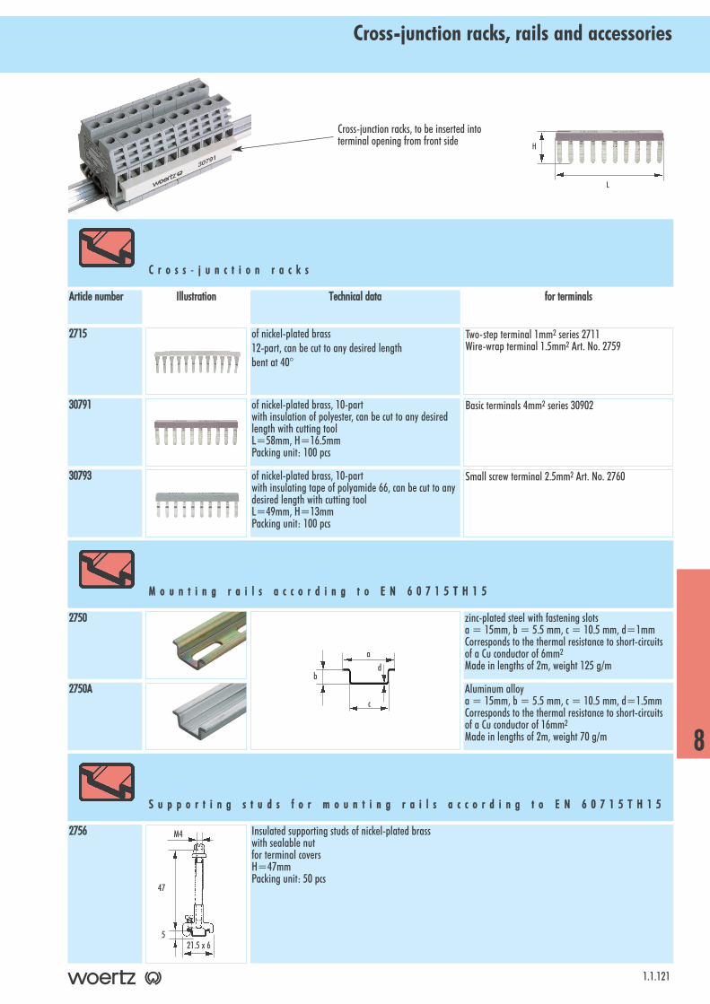
Cross-junction racks, rails and accessories
1.1.121
C r o s s - jj u n c t i o n rr a c k s
for tterminalsTechnical ddataIllustrationArticle nnumber
Two-step terminal 1mm2 series 2711Wire-wrap terminal 1.5mm2 Art. No. 2759
of nickel-plated brass12-part, can be cut to any desired lengthbent at 40°
2715
Basic terminals 4mm2 series 30902of nickel-plated brass, 10-partwith insulation of polyester, can be cut to any desiredlength with cutting toolL=58mm, H=16.5mmPacking unit: 100 pcs
30791
Small screw terminal 2.5mm2 Art. No. 2760of nickel-plated brass, 10-partwith insulating tape of polyamide 66, can be cut to anydesired length with cutting toolL=49mm, H=13mmPacking unit: 100 pcs
30793
2750A
Insulated supporting studs of nickel-plated brasswith sealable nutfor terminal coversH=47mmPacking unit: 50 pcs
2756
H
L
M o u n t i n g rr a i l s aa c c o r d i n g tt o EE N 6 0 7 1 5 T H 1 5
zinc-plated steel with fastening slotsa = 15mm, b = 5.5 mm, c = 10.5 mm, d=1mmCorresponds to the thermal resistance to short-circuitsof a Cu conductor of 6mm2
Made in lengths of 2m, weight 125 g/m
2750
Aluminum alloya = 15mm, b = 5.5 mm, c = 10.5 mm, d=1.5mmCorresponds to the thermal resistance to short-circuitsof a Cu conductor of 16mm2
Made in lengths of 2m, weight 70 g/m
S u p p o r t i n g ss t u d s ff o r mm o u n t i n g rr a i l s aa c c o r d i n g tt o EE N 6 0 7 1 5 T H 1 5
8
Cross-junction racks, to be inserted intoterminal opening from front side
c
da
b
21.5 x 65
M4
47

Angled support bracket and terminal covers
1.1.122
T e r m i n a l cc o v e r s aa n d aa c c e s s o r i e s
for tterminalsTechnical ddataIllustrationArticle nnumber
Some applications and codes require the connection terminals tobe covered to prevent any accidental contact. Covers of yellow pla-stic with a warning arrow in black are available in different dimen-sions.
These covers are fixed on the central threads of the terminals with two fastening screws of poly-amide 66. Covers available for 4, 5, 6, 7 or 8 terminals. Sealing eyelets can be used to avoid any damage to the terminal covers.
A
B
Basic terminals 4mm2 series 30902of plastic, yellowwith black markingwith 2 fastening screws of polyamide 66Packing unit: 10 pcs1mm thick, 24 mm high
3894/4: A=18mm, B=26mm3894/5: A=24mm, B=32mm3894/6: A=30mm, B=38mm3894/7: A=36mm, B=44mm3894/8: A=42mm, B=50mm
3894/4
3894/5
3894/6
3894/7
3894/8
For bending over the heads of the fastening screws.Hole ∅ =3.2mm for fastening screws M2.5 and M3Packing unit: 100 pcs
81440
M3x20 of polyamide 66
M3x25 of polyamide 66Packing unit: 50 pcs
01062
3512
Terminal ccoversfor 4 terminals
for 5 terminals
for 6 terminals
for 7 terminals
for 8 terminals
Fastening sscrews
Sealing sscrews
Sealing eeyelets
A n g l e d ss u p p o r t bb r a c k e t
of sheet steel 2 mm, galvanizedLength 89mm, width 20 mm, height 48mmangle of 30°with screw thread M6for an accessible arrangement of terminals
Packing unit: 10 pcs
80360/30
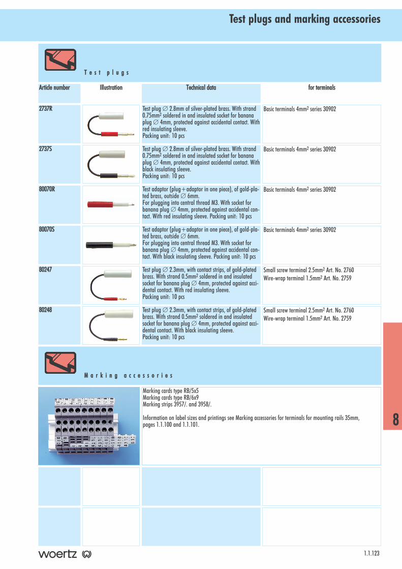
Test plugs and marking accessories
1.1.123
T e s t pp l u g s
for tterminalsTechnical ddataIllustrationArticle nnumber
Basic terminals 4mm2 series 30902Test plug ∅ 2.8mm of silver-plated brass. With strand0.75mm2 soldered in and insulated socket for bananaplug ∅ 4mm, protected against accidental contact. Withred insulating sleeve.Packing unit: 10 pcs
2737R
Basic terminals 4mm2 series 30902Test plug ∅ 2.8mm of silver-plated brass. With strand0.75mm2 soldered in and insulated socket for bananaplug ∅ 4mm, protected against accidental contact. Withblack insulating sleeve.Packing unit: 10 pcs
2737S
Basic terminals 4mm2 series 30902Test adaptor (plug+adaptor in one piece), of gold-pla-ted brass, outside ∅ 6mm.For plugging into central thread M3. With socket forbanana plug ∅ 4mm, protected against accidental con-tact. With red insulating sleeve. Packing unit: 10 pcs
80070R
Basic terminals 4mm2 series 30902Test adaptor (plug+adaptor in one piece), of gold-pla-ted brass, outside ∅ 6mm.For plugging into central thread M3. With socket forbanana plug ∅ 4mm, protected against accidental con-tact. With black insulating sleeve. Packing unit: 10 pcs
80070S
Small screw terminal 2.5mm2 Art. No. 2760Wire-wrap terminal 1.5mm2 Art. No. 2759
Test plug ∅ 2.3mm, with contact strips, of gold-platedbrass. With strand 0.5mm2 soldered in and insulatedsocket for banana plug ∅ 4mm, protected against acci-dental contact. With red insulating sleeve.Packing unit: 10 pcs
80247
Small screw terminal 2.5mm2 Art. No. 2760Wire-wrap terminal 1.5mm2 Art. No. 2759
Test plug ∅ 2.3mm, with contact strips, of gold-platedbrass. With strand 0.5mm2 soldered in and insulatedsocket for banana plug ∅ 4mm, protected against acci-dental contact. With black insulating sleeve.Packing unit: 10 pcs
80248
Marking cards type RB/5x5Marking cards type RB/6x9Marking strips 3957/. and 3958/.
Information on label sizes and printings see Marking accessories for terminals for mounting rails 35mm,pages 1.1.100 and 1.1.101.
M a r k i n g aa c c e s s o r i e s
8
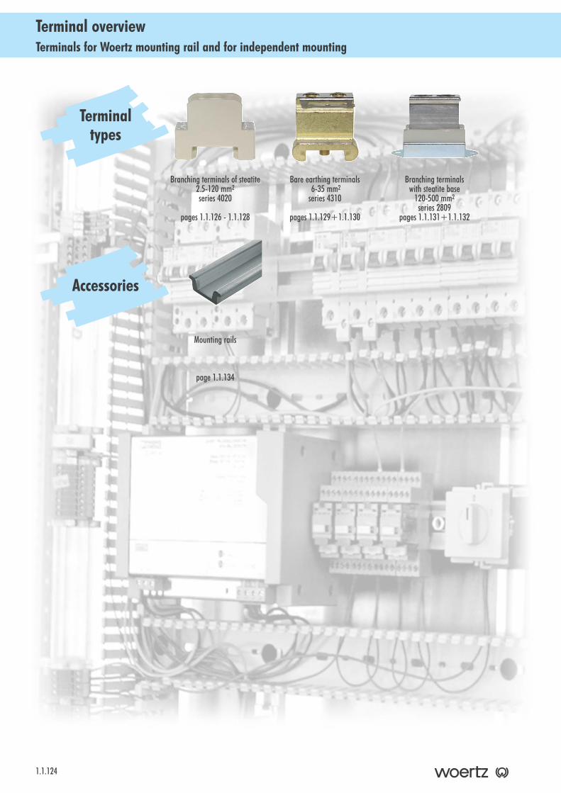
Terminals for Woertz mounting rail and for independent mountingTerminal overview
1.1.124
Bare earthing terminals6-35 mm2
series 4310
pages 1.1.129+1.1.130
Branching terminals of steatite 2.5-120 mm2
series 4020
pages 1.1.126 - 1.1.128
Branching terminals with steatite base
120-500 mm2
series 2809pages 1.1.131+1.1.132
Terminaltypes
Accessories
Mounting rails
page 1.1.134
T e r m i n a l ss e r i e s p a g e s 11 . 1 . 1 2 5 tt o 11 . 1 . 1 3 2B r a n c h i n g t e r m i n a l s o f s t e a t i t e 2 . 5 - 1 2 0 m m 2 . . . . 1 . 1 . 1 2 6 - 1 . 1 . 1 2 8B a r e e a r t h i n g t e r m i n a l s 6 - 3 5 m m 2 . . . . . . . . . . 1 . 1 . 1 2 9 + 1 . 1 . 1 3 0B r a n c h i n g t e r m i n a l s w i t h s t e a t i t e b a s e 1 2 0 - 5 0 0 m m 2 . . . . . . . . . . . . . . . . . . . . . . . . 1 . 1 3 1 + 1 . 1 . 1 3 2
1.1.125
IndexBranching terminals for Woertz mounting rail and for independent mounting
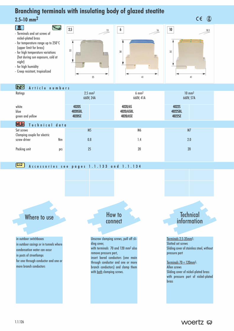
2.5-10 mm2Branching terminals with insulating body of glazed steatite
1.1.126
- Terminals and set screws of nickel-plated brass
- for temperature range up to 250°C (upper limit for brass)
- for high temperature variations(hot during sun exposure, cold atnight)
- for high humidity- Creep resistant, tropicalized
A r t i c l e nn u m b e r sRatings 2.5 mm2
660V, 24A6 mm2
660V, 41A10 mm2
660V, 57A
whitebluegreen and yellow
4020S4020SBL4020SE
4020/6S4020/6SBL4020/6SE
4022S4022SBL4022SE
T e c h n i c a l dd a t aSet screwsClamping couple for electricscrew-driver Nm
Packing unit pcs
M5
0.8
25
M6
1.4
20
M7
2.0
20
A c c e s s o r i e s ss e e pp a g e s 11 . 1 . 1 3 3 aa n d 11 . 1 . 1 3 4
22
35
13
30
41
16
32
41
18.52.5 6 10
Where to use
in outdoor switchboxesin outdoor casings or in tunnels wherecondensation water can occurin posts of streetlampsfor one through conductor and one ormore branch conductors
How toconnect
Unscrew clamping screws, pull off sli-ding cover, with terminals 70 and 120 mm2 alsoremove pressure part,insert bared conductors (one mainthrough conductor and one or morebranch conductors) and clamp themwith both clamping screws.
Technicalinformation
Terminals 2.5-35mm2:Slotted set screwsSliding cover of stainless steel, withoutpressure part
Terminals 70+120mm2:Allen screwsSliding cover of nickel-plated brasswith pressure part of nickel-platedbrass
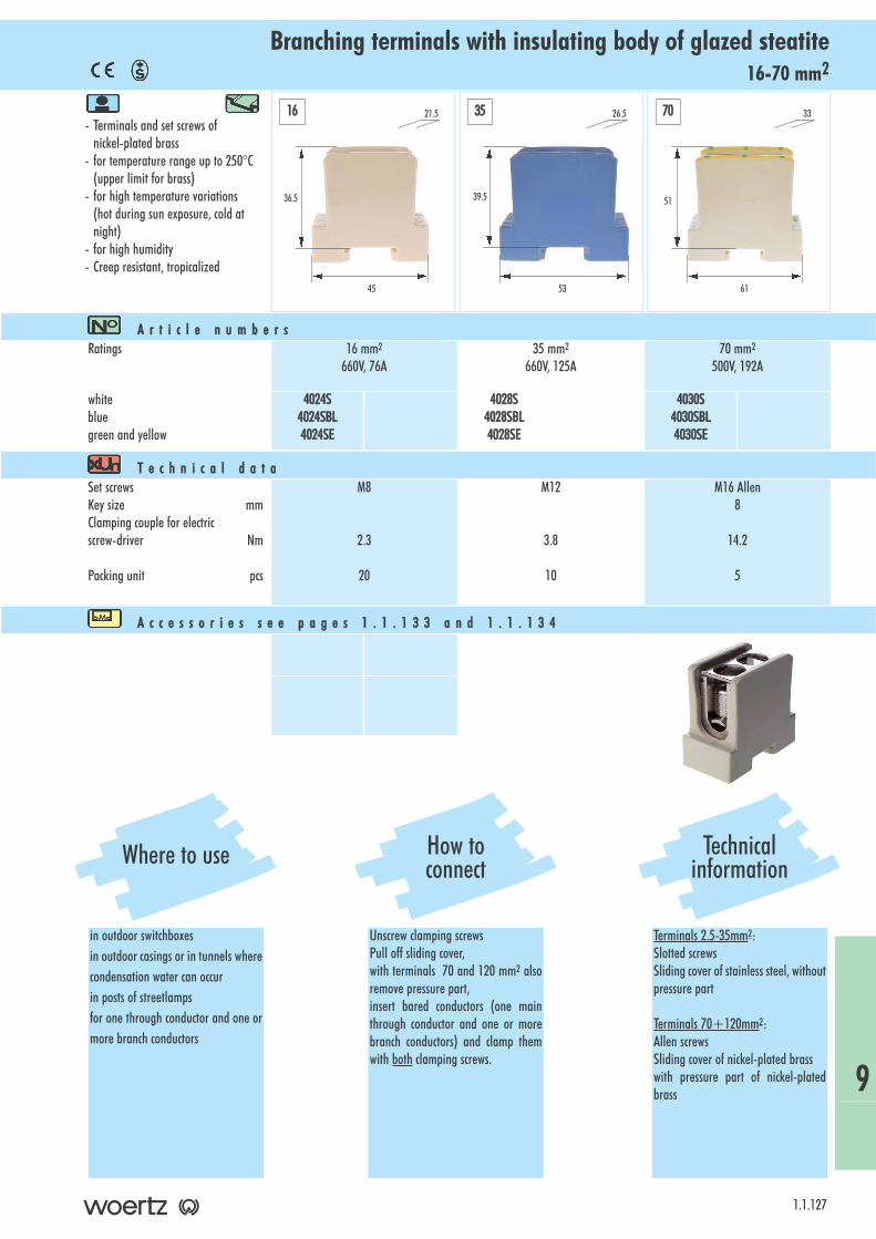
16-70 mm2Branching terminals with insulating body of glazed steatite
- Terminals and set screws of nickel-plated brass
- for temperature range up to 250°C (upper limit for brass)
- for high temperature variations(hot during sun exposure, cold at night)
- for high humidity- Creep resistant, tropicalized
1.1.127
A r t i c l e nn u m b e r sRatings 16 mm2
660V, 76A35 mm2
660V, 125A70 mm2
500V, 192A
whitebluegreen and yellow
4024S4024SBL4024SE
4028S4028SBL4028SE
4030S4030SBL4030SE
T e c h n i c a l dd a t aSet screwsKey size mmClamping couple for electricscrew-driver Nm
Packing unit pcs
M8
2.3
20
M12
3.8
10
M16 Allen8
14.2
5
A c c e s s o r i e s ss e e pp a g e s 11 . 1 . 1 3 3 aa n d 11 . 1 . 1 3 4
36.5
45
21.5
39.5
53
26.5
51
61
3316 35 70
Where to use
in outdoor switchboxesin outdoor casings or in tunnels wherecondensation water can occurin posts of streetlampsfor one through conductor and one ormore branch conductors
How toconnect
Unscrew clamping screwsPull off sliding cover, with terminals 70 and 120 mm2 alsoremove pressure part,insert bared conductors (one mainthrough conductor and one or morebranch conductors) and clamp themwith both clamping screws.
Technicalinformation
Terminals 2.5-35mm2:Slotted screwsSliding cover of stainless steel, withoutpressure part
Terminals 70+120mm2:Allen screwsSliding cover of nickel-plated brasswith pressure part of nickel-platedbrass 9
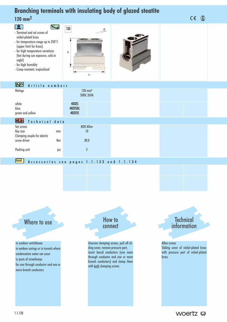
120 mm2Branching terminals with insulating body of glazed steatite
1.1.128
- Terminal and set screws of nickel-plated brass
- for temperature range up to 250°C (upper limit for brass)
- for high temperature variations(hot during sun exposure, cold at night)
- for high humidity- Creep resistant, tropicalized
A r t i c l e nn u m b e r sRatings 120 mm2
500V, 269A
whitebluegreen and yellow
4032S4032SBL4032SE
T e c h n i c a l dd a t aSet screwsKey size mmClamping couple for electricscrew-driver Nm
Packing unit pcs
M20 Allen10
30.0
5
A c c e s s o r i e s ss e e pp a g e s 11 . 1 . 1 3 3 aa n d 11 . 1 . 1 3 4
61
71
40120
Where to use
in outdoor switchboxesin outdoor casings or in tunnels wherecondensation water can occurin posts of streetlampsfor one through conductor and one ormore branch conductors
How toconnect
Unscrew clamping screws, pull off sli-ding cover, remove pressure part,insert bared conductors (one mainthrough conductor and one or morebranch conductors) and clamp themwith both clamping screws.
Technicalinformation
Allen screwsSliding cover of nickel-plated brass with pressure part of nickel-platedbrass
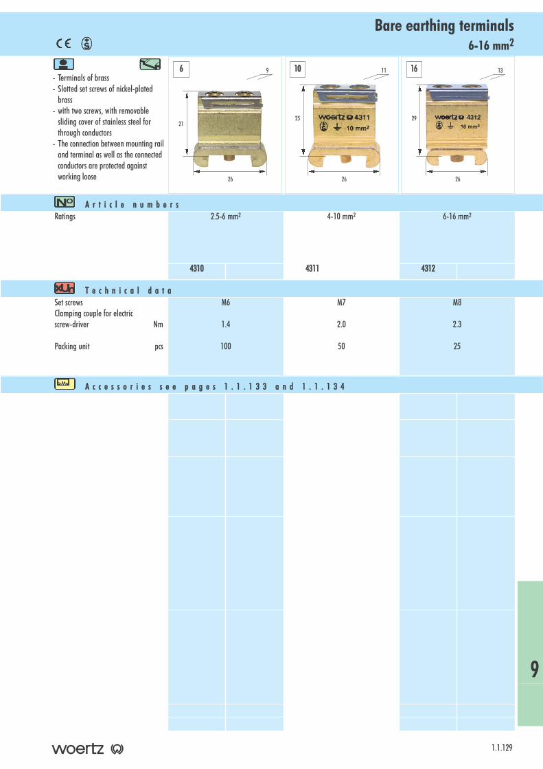
6-16 mm2Bare earthing terminals
- Terminals of brass- Slotted set screws of nickel-plated
brass- with two screws, with removable
sliding cover of stainless steel forthrough conductors
- The connection between mounting railand terminal as well as the connected conductors are protected against working loose
1.1.129
A r t i c l e nn u m b e r sRatings 2.5-6 mm2 4-10 mm2 6-16 mm2
4310 4311 4312
T e c h n i c a l dd a t aSet screwsClamping couple for electricscrew-driver Nm
Packing unit pcs
M6
1.4
100
M7
2.0
50
M8
2.3
25
A c c e s s o r i e s ss e e pp a g e s 11 . 1 . 1 3 3 aa n d 11 . 1 . 1 3 4
21
26
9
25
26
11
29
26
136 10 16
9
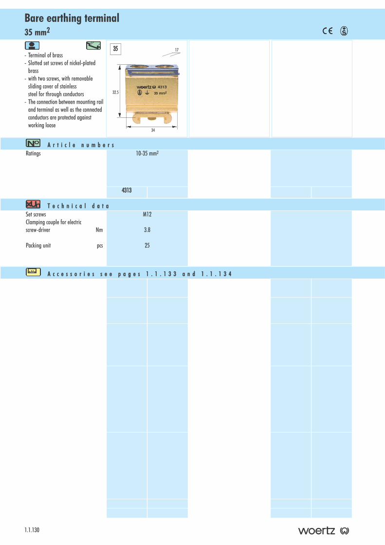
35 mm2Bare earthing terminal
1.1.130
- Terminal of brass- Slotted set screws of nickel-plated
brass- with two screws, with removable
sliding cover of stainless steel for through conductors
- The connection between mounting railand terminal as well as the connected conductors are protected against working loose
A r t i c l e nn u m b e r sRatings 10-35 mm2
4313
T e c h n i c a l dd a t aSet screwsClamping couple for electricscrew-driver Nm
Packing unit pcs
M12
3.8
25
A c c e s s o r i e s ss e e pp a g e s 11 . 1 . 1 3 3 aa n d 11 . 1 . 1 3 4
32.5
34
1735
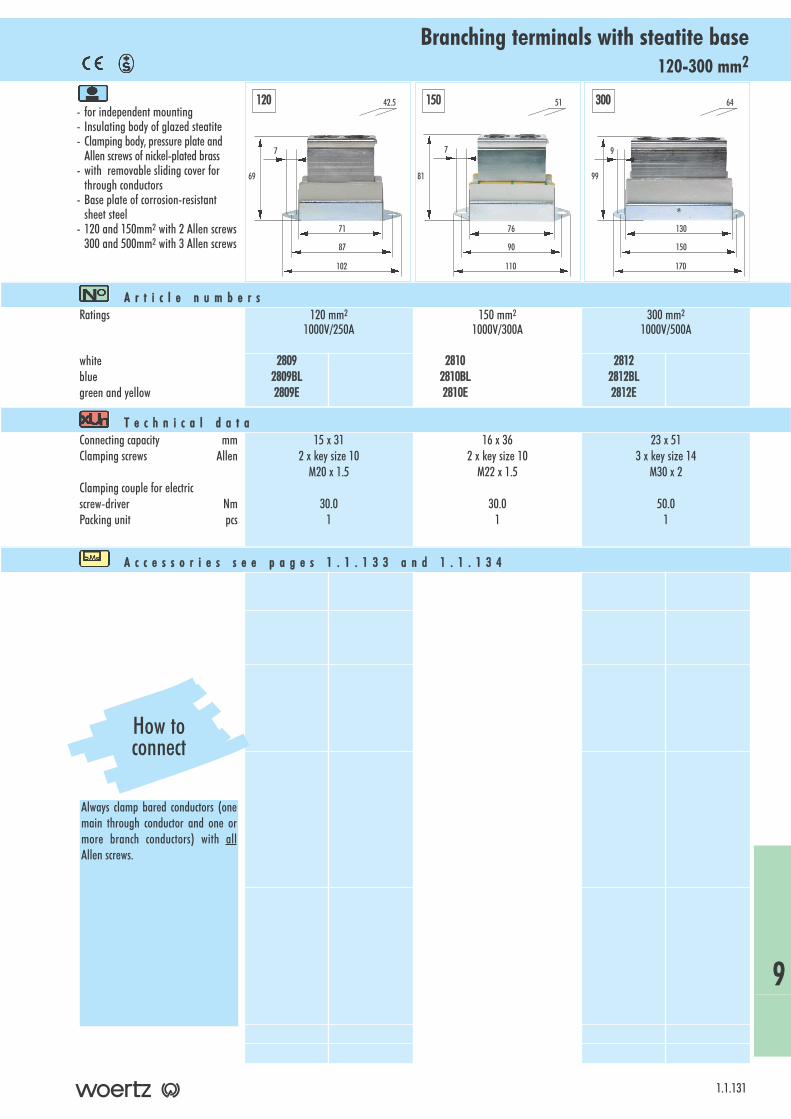
120-300 mm2Branching terminals with steatite base
- for independent mounting- Insulating body of glazed steatite- Clamping body, pressure plate and
Allen screws of nickel-plated brass- with removable sliding cover for
through conductors- Base plate of corrosion-resistant
sheet steel- 120 and 150mm2 with 2 Allen screws
300 and 500mm2 with 3 Allen screws
1.1.131
A r t i c l e nn u m b e r sRatings 120 mm2
1000V/250A150 mm2
1000V/300A300 mm2
1000V/500A
whitebluegreen and yellow
28092809BL2809E
28102810BL2810E
28122812BL2812E
T e c h n i c a l dd a t aConnecting capacity mmClamping screws Allen
Clamping couple for electricscrew-driver NmPacking unit pcs
15 x 312 x key size 10
M20 x 1.5
30.01
16 x 362 x key size 10
M22 x 1.5
30.01
23 x 513 x key size 14
M30 x 2
50.01
A c c e s s o r i e s ss e e pp a g e s 11 . 1 . 1 3 3 aa n d 11 . 1 . 1 3 4
69
71
42.5120 150 300
87
102
7
81
76
51
90
110
7
99
130
64
150
170
9
9
How toconnect
Always clamp bared conductors (onemain through conductor and one ormore branch conductors) with allAllen screws.

500 mm2Branching terminals with steatite base
1.1.132
- for independent mounting- Insulating body of glazed steatite- Clamping body, pressure plate and
Allen screws of nickel-plated brass- with removable sliding cover for
through conductors- Base plate of corrosion-resistant
sheet steel- with 3 Allen screws
A r t i c l e nn u m b e r sRatings 500 mm2
1000V/650A
greybluegreen and yellow
28142814BL2814E
T e c h n i c a l dd a t aConnecting capacity mmClamping screws AllenThreadClamping couple for electricscrew-driver NmPacking unit pcs
30 x 623 x key size 17
G 1 1/8”
50.01
A c c e s s o r i e s ss e e pp a g e s 11 . 1 . 1 3 3 aa n d 11 . 1 . 1 3 4
500
120
156
82
190
215
12
How toconnect
Always clamp bared conductors (onemain through conductor and one ormore branch conductors) with allthree Allen screws.
A c c e s s o r i e s p a g e s 11 . 1 . 1 3 3 ++ 11 . 1 . 1 3 4R a i l s a n d a c c e s s o r i e s . . . . . . . . . . . . . . . . . . . . . . . 1 . 1 . 1 3 4
1.1.133
Accessories for terminals for Woertz mounting rail

Woertz rail and accessories
1.1.134
W o e r t z rr a i l
Technical ddataIllustrationArticle nnumber
of aluminum alloyCorresponds to the thermal resistance to short-circuitsof a Cu conductor of 50mm2
Made in lengths of 3m, weight 160 g/m
4050A
Dimension iillustration
with clamp and sealing screw,of nickel-plated brass, insulated bolt,for mounting on Woertz railW=16mm, L=26mm, H=31mmPacking unit 50 pcs
4490B
with clamp and sealing screw,of nickel-plated brass, insulated bolt,for mounting on Woertz railW=16mm, L=26mm, H=56mmPacking unit 50 pcs
4491B
5mm wide, of nickel-plated brass,with screw M3, for mounting on Woertz rail
Packing unit 50 pcs
4054
10mm wide, of thermosetting plastic, black
Packing unit 150 pcs
4053/10J
S u p p o r t i n g ss t u d s
C l a m p
S p a c e r
2
15
19
1.57
A n g l e d ss u p p o r t bb r a c k e t
of sheet steel 2 mm, galvanizedLength 89mm, width 20 mm, height 48mmangle of 30°with screw thread M6for an accessible arrangement of terminals
Packing unit: 10 pcs
80360/30
B
M4H
L
1.1.135
ORDER
NUMBER
INDEX

2711BL . . . . . . . . . . . . . . . . . . .1.1.1132711GR . . . . . . . . . . . . . . . . . . .1.1.1132712GR . . . . . . . . . . . . . . . . . . .1.1.1182713GR . . . . . . . . . . . . . . . . . . .1.1.1182715 . . . . . . . . . . . . . . . . . . . . .1.1.1212721 . . . . . . . . . . . . . . . . . . . . .1.1.1112736R . . . . . . . . . . . . . . . . . . . . .1.1.982736S . . . . . . . . . . . . . . . . . . . . .1.1.982737R . . . . . . . . . . . . . . . . . . . . .1.1.982737S . . . . . . . . . . . . . . . . . . . . .1.1.982750 . . . . . . . . . . . . . . . . . . . . .1.1.1212750A . . . . . . . . . . . . . . . . . . . .1.1.1212754 . . . . . . . . . . . . . . . . . . . . .1.1.1192754A . . . . . . . . . . . . . . . . . . . .1.1.1192756 . . . . . . . . . . . . . . . . . . . . .1.1.1212759 . . . . . . . . . . . . . . . . . . . . .1.1.1152760 . . . . . . . . . . . . . . . . . . . . .1.1.1142762 . . . . . . . . . . . . . . . . . . . . .1.1.1182763 . . . . . . . . . . . . . . . . . . . . .1.1.1182764 . . . . . . . . . . . . . . . . . . . . .1.1.1182765 . . . . . . . . . . . . . . . . . . . . .1.1.1192809 . . . . . . . . . . . . . . . . . . . . .1.1.1312809BL . . . . . . . . . . . . . . . . . . .1.1.1312809E . . . . . . . . . . . . . . . . . . . .1.1.1312810 . . . . . . . . . . . . . . . . . . . . .1.1.1312810BL . . . . . . . . . . . . . . . . . . .1.1.1312810E . . . . . . . . . . . . . . . . . . . .1.1.1312812 . . . . . . . . . . . . . . . . . . . . .1.1.1312812BL . . . . . . . . . . . . . . . . . . .1.1.1312812E . . . . . . . . . . . . . . . . . . . .1.1.1312814 . . . . . . . . . . . . . . . . . . . . .1.1.1322814BL . . . . . . . . . . . . . . . . . . .1.1.1322814E . . . . . . . . . . . . . . . . . . . .1.1.1323400A . . . . . . . . . . . . . . . . . . . .1.1.1053401 . . . . . . . . . . . . . . . . . . . . .1.1.1053401/L . . . . . . . . . . . . . . . . . . .1.1.1053401IN . . . . . . . . . . . . . . . . . . .1.1.1053410BL . . . . . . . . . . . . . . . . . . . .1.1.243410GR . . . . . . . . . . . . . . . . . . . .1.1.243411 . . . . . . . . . . . . . . . . . . . . . .1.1.723412 . . . . . . . . . . . . . . . . . . . . . .1.1.753418 . . . . . . . . . . . . . . . . . . . . . .1.1.783424BL . . . . . . . . . . . . . . . . . . . .1.1.383424E . . . . . . . . . . . . . . . . . . . . .1.1.383424GR . . . . . . . . . . . . . . . . . . . .1.1.383425BL . . . . . . . . . . . . . . . . . . . .1.1.383425E . . . . . . . . . . . . . . . . . . . . .1.1.383425GR . . . . . . . . . . . . . . . . . . . .1.1.383426BL . . . . . . . . . . . . . . . . . . . .1.1.393426E . . . . . . . . . . . . . . . . . . . . .1.1.393426GR . . . . . . . . . . . . . . . . . . . .1.1.393427BL . . . . . . . . . . . . . . . . . . . .1.1.393427E . . . . . . . . . . . . . . . . . . . . .1.1.393427GR . . . . . . . . . . . . . . . . . . . .1.1.393428BL . . . . . . . . . . . . . . . . . . . .1.1.393428E . . . . . . . . . . . . . . . . . . . . .1.1.39
3428GR . . . . . . . . . . . . . . . . . . . .1.1.393429BL . . . . . . . . . . . . . . . . . . . .1.1.403429GR . . . . . . . . . . . . . . . . . . . .1.1.403430BL . . . . . . . . . . . . . . . . . . . .1.1.243430E . . . . . . . . . . . . . . . . . . . . .1.1.243430GR . . . . . . . . . . . . . . . . . . . .1.1.243430GRBL . . . . . . . . . . . . . . . . . .1.1.243430OR . . . . . . . . . . . . . . . . . . . .1.1.243430/1P . . . . . . . . . . . . . . . . . . .1.1.253430/1PBL . . . . . . . . . . . . . . . . .1.1.253430/4GRV . . . . . . . . . . . . . . . . .1.1.263430/4V . . . . . . . . . . . . . . . . . . .1.1.263431 . . . . . . . . . . . . . . . . . . . . . .1.1.723432 . . . . . . . . . . . . . . . . . . . . . .1.1.753433 . . . . . . . . . . . . . . . . . . . . . .1.1.453434 . . . . . . . . . . . . . . . . . . . . . .1.1.453435 . . . . . . . . . . . . . . . . . . . . . .1.1.433436 . . . . . . . . . . . . . . . . . . . . . .1.1.433436/4V . . . . . . . . . . . . . . . . . . .1.1.413436/10 . . . . . . . . . . . . . . . . . . .1.1.433436/10V . . . . . . . . . . . . . . . . . .1.1.413436V . . . . . . . . . . . . . . . . . . . . .1.1.413437 . . . . . . . . . . . . . . . . . . . . . .1.1.443437V . . . . . . . . . . . . . . . . . . . . .1.1.423438 . . . . . . . . . . . . . . . . . . . . . .1.1.443438V . . . . . . . . . . . . . . . . . . . . .1.1.423440GR . . . . . . . . . . . . . . . . . . . .1.1.683444 . . . . . . . . . . . . . . . . . . . . . .1.1.743445 . . . . . . . . . . . . . . . . . . . . . .1.1.773450BL . . . . . . . . . . . . . . . . . . . .1.1.163450BR . . . . . . . . . . . . . . . . . . . .1.1.173450E . . . . . . . . . . . . . . . . . . . . .1.1.163450GE . . . . . . . . . . . . . . . . . . . .1.1.173450GN . . . . . . . . . . . . . . . . . . .1.1.173450GR . . . . . . . . . . . . . . . . . . . .1.1.163450OR . . . . . . . . . . . . . . . . . . . .1.1.173450RO . . . . . . . . . . . . . . . . . . . .1.1.173450SW . . . . . . . . . . . . . . . . . . .1.1.173450WE . . . . . . . . . . . . . . . . . . .1.1.173452/6BL . . . . . . . . . . . . . . . . . .1.1.163452/6E . . . . . . . . . . . . . . . . . . .1.1.163452/6GR . . . . . . . . . . . . . . . . . .1.1.163452/10BL . . . . . . . . . . . . . . . . .1.1.173452/10E . . . . . . . . . . . . . . . . . .1.1.173452/10GR . . . . . . . . . . . . . . . . .1.1.173452/16BL . . . . . . . . . . . . . . . . .1.1.173452/16E . . . . . . . . . . . . . . . . . .1.1.173452/16GR . . . . . . . . . . . . . . . . .1.1.173459 . . . . . . . . . . . . . . . . . . . . .1.1.1073460 . . . . . . . . . . . . . . . . . . . . . .1.1.723461 . . . . . . . . . . . . . . . . . . . . . .1.1.753464 . . . . . . . . . . . . . . . . . . . . . .1.1.723465 . . . . . . . . . . . . . . . . . . . . . .1.1.753468BL . . . . . . . . . . . . . . . . . . . .1.1.593468E . . . . . . . . . . . . . . . . . . . . .1.1.593468GR . . . . . . . . . . . . . . . . . . . .1.1.59
3469BL . . . . . . . . . . . . . . . . . . . .1.1.593469E . . . . . . . . . . . . . . . . . . . . .1.1.593469GR . . . . . . . . . . . . . . . . . . . .1.1.593472BL . . . . . . . . . . . . . . . . . . . .1.1.463473BL . . . . . . . . . . . . . . . . . . . .1.1.463474BL . . . . . . . . . . . . . . . . . . . .1.1.733475BL . . . . . . . . . . . . . . . . . . . .1.1.733477BL . . . . . . . . . . . . . . . . . . . .1.1.463490 . . . . . . . . . . . . . . . . . . . . .1.1.1053490/L . . . . . . . . . . . . . . . . . . .1.1.1053497 . . . . . . . . . . . . . . . . . . . . . .1.1.763497M5 . . . . . . . . . . . . . . . . . . . .1.1.763499 . . . . . . . . . . . . . . . . . . . . . .1.1.763499M5 . . . . . . . . . . . . . . . . . . . .1.1.763506 . . . . . . . . . . . . . . . . . . . . . .1.1.763507 . . . . . . . . . . . . . . . . . . . . . .1.1.763508 . . . . . . . . . . . . . . . . . . . . . .1.1.763509 . . . . . . . . . . . . . . . . . . . . . .1.1.763512 . . . . . . . . . . . . . . . . . . . . . .1.1.873516 . . . . . . . . . . . . . . . . . . . . . .1.1.733517 . . . . . . . . . . . . . . . . . . . . . .1.1.733518 . . . . . . . . . . . . . . . . . . . . . .1.1.733519 . . . . . . . . . . . . . . . . . . . . . .1.1.733772PR . . . . . . . . . . . . . . . . . . . .1.1.983772PS . . . . . . . . . . . . . . . . . . . .1.1.983821 . . . . . . . . . . . . . . . . . . . . . .1.1.953826/4 . . . . . . . . . . . . . . . . . . . .1.1.873838 . . . . . . . . . . . . . . . . . . . . . .1.1.973839 . . . . . . . . . . . . . . . . . . . . . .1.1.973856 . . . . . . . . . . . . . . . . . . . . . .1.1.973859 . . . . . . . . . . . . . . . . . . . . . .1.1.973867/4 . . . . . . . . . . . . . . . . . . . .1.1.893868/4 . . . . . . . . . . . . . . . . . . . .1.1.873869/4 . . . . . . . . . . . . . . . . . . . .1.1.903886/4 . . . . . . . . . . . . . . . . . . . .1.1.883887/4 . . . . . . . . . . . . . . . . . . . .1.1.883894/4 . . . . . . . . . . . . . . . . . . . .1.1.883954 . . . . . . . . . . . . . . . . . . . . .1.1.1023955/4 . . . . . . . . . . . . . . . . . . .1.1.1023955/6 . . . . . . . . . . . . . . . . . . .1.1.1023957 . . . . . . . . . . . . . . . . . . . . .1.1.1003958/1 . . . . . . . . . . . . . . . . . . .1.1.1003958/A . . . . . . . . . . . . . . . . . . .1.1.1004020S . . . . . . . . . . . . . . . . . . . .1.1.1264020SBL . . . . . . . . . . . . . . . . . .1.1.1264020SE . . . . . . . . . . . . . . . . . . .1.1.1264020/6S . . . . . . . . . . . . . . . . . .1.1.1264020/6SBL . . . . . . . . . . . . . . . .1.1.1264020/6SE . . . . . . . . . . . . . . . . .1.1.1264022S . . . . . . . . . . . . . . . . . . . .1.1.1264022SBL . . . . . . . . . . . . . . . . . .1.1.1264022SE . . . . . . . . . . . . . . . . . . .1.1.1264024S . . . . . . . . . . . . . . . . . . . .1.1.1274024SBL . . . . . . . . . . . . . . . . . .1.1.1274024SE . . . . . . . . . . . . . . . . . . .1.1.1274028S . . . . . . . . . . . . . . . . . . . .1.1.127
Order number index
4028SBL . . . . . . . . . . . . . . . . . .1.1.1274028SE . . . . . . . . . . . . . . . . . . .1.1.1274030S . . . . . . . . . . . . . . . . . . . .1.1.1274030SBL . . . . . . . . . . . . . . . . . .1.1.1274030SE . . . . . . . . . . . . . . . . . . .1.1.1274032S . . . . . . . . . . . . . . . . . . . .1.1.1284032SBL . . . . . . . . . . . . . . . . . .1.1.1284032SE . . . . . . . . . . . . . . . . . . .1.1.1284050A . . . . . . . . . . . . . . . . . . . .1.1.1344053/10J . . . . . . . . . . . . . . . . . .1.1.1344054 . . . . . . . . . . . . . . . . . . . . .1.1.1344310 . . . . . . . . . . . . . . . . . . . . .1.1.1294311 . . . . . . . . . . . . . . . . . . . . .1.1.1294312 . . . . . . . . . . . . . . . . . . . . .1.1.1294313 . . . . . . . . . . . . . . . . . . . . .1.1.1304490B . . . . . . . . . . . . . . . . . . . .1.1.1344491B . . . . . . . . . . . . . . . . . . . .1.1.1349072 . . . . . . . . . . . . . . . . . . . . .1.1.10601062 . . . . . . . . . . . . . . . . . . . .1.1.12201068 . . . . . . . . . . . . . . . . . . . . .1.1.8701162 . . . . . . . . . . . . . . . . . . . . .1.1.8701165 . . . . . . . . . . . . . . . . . . . . .1.1.9008569 . . . . . . . . . . . . . . . . . . . . .1.1.8917402 . . . . . . . . . . . . . . . . . . . . .1.1.8730003 . . . . . . . . . . . . . . . . . . . . .1.1.5630005 . . . . . . . . . . . . . . . . . . . . .1.1.5530008 . . . . . . . . . . . . . . . . . . . . .1.1.5530009 . . . . . . . . . . . . . . . . . . . . .1.1.5630025 . . . . . . . . . . . . . . . . . . . . .1.1.7430041 . . . . . . . . . . . . . . . . . . . . .1.1.5630112 . . . . . . . . . . . . . . . . . . . . .1.1.7430123 . . . . . . . . . . . . . . . . . . . . .1.1.4930124 . . . . . . . . . . . . . . . . . . . . .1.1.4830127 . . . . . . . . . . . . . . . . . . . . .1.1.4930128BL . . . . . . . . . . . . . . . . . . .1.1.3830128E . . . . . . . . . . . . . . . . . . . .1.1.3830128GR . . . . . . . . . . . . . . . . . . .1.1.3830130 . . . . . . . . . . . . . . . . . . . . .1.1.4830132 . . . . . . . . . . . . . . . . . . . . .1.1.9530133 . . . . . . . . . . . . . . . . . . . . .1.1.9630134 . . . . . . . . . . . . . . . . . . . . .1.1.9630134/24 . . . . . . . . . . . . . . . . . .1.1.9630134/230 . . . . . . . . . . . . . . . . .1.1.9630137GR . . . . . . . . . . . . . . . . . . .1.1.6930138GR . . . . . . . . . . . . . . . . . . .1.1.6930139 . . . . . . . . . . . . . . . . . . . . .1.1.7430143GR . . . . . . . . . . . . . . . . . . .1.1.6930146 . . . . . . . . . . . . . . . . . . . . .1.1.5330150BL . . . . . . . . . . . . . . . . . . .1.1.1630150BR . . . . . . . . . . . . . . . . . . .1.1.1730150E . . . . . . . . . . . . . . . . . . . .1.1.1630150GE . . . . . . . . . . . . . . . . . . .1.1.1730150GN . . . . . . . . . . . . . . . . . .1.1.1730150GR . . . . . . . . . . . . . . . . . . .1.1.1630150OR . . . . . . . . . . . . . . . . . . .1.1.1730150RO . . . . . . . . . . . . . . . . . . .1.1.17
30150SW . . . . . . . . . . . . . . . . . .1.1.1730150WE . . . . . . . . . . . . . . . . . .1.1.1730158 . . . . . . . . . . . . . . . . . . . . .1.1.7430159 . . . . . . . . . . . . . . . . . . . . .1.1.7430168 . . . . . . . . . . . . . . . . . . . . .1.1.5030172 . . . . . . . . . . . . . . . . . . . . .1.1.5030176 . . . . . . . . . . . . . . . . . . . . .1.1.5430179 . . . . . . . . . . . . . . . . . . . . .1.1.8630181 . . . . . . . . . . . . . . . . . . . . .1.1.6230182 . . . . . . . . . . . . . . . . . . . . .1.1.6230191 . . . . . . . . . . . . . . . . . . . . .1.1.5230195 . . . . . . . . . . . . . . . . . . . . .1.1.5230197 . . . . . . . . . . . . . . . . . . . . .1.1.4730199 . . . . . . . . . . . . . . . . . . . . .1.1.7830200 . . . . . . . . . . . . . . . . . . . . .1.1.4730205 . . . . . . . . . . . . . . . . . . . . .1.1.9630224/25A . . . . . . . . . . . . . . . . .1.1.6330224/60A . . . . . . . . . . . . . . . . .1.1.6330224/100A . . . . . . . . . . . . . . . .1.1.6330224/160A . . . . . . . . . . . . . . . .1.1.6430224/160B . . . . . . . . . . . . . . . .1.1.6430228 . . . . . . . . . . . . . . . . . . . . .1.1.5430285M8BL . . . . . . . . . . . . . . . .1.1.6630285M8GR . . . . . . . . . . . . . . . .1.1.6630285M12BL . . . . . . . . . . . . . . .1.1.6630285M12GR . . . . . . . . . . . . . . .1.1.6630286M8BL . . . . . . . . . . . . . . . .1.1.6530286M8GR . . . . . . . . . . . . . . . .1.1.6530286M10BL . . . . . . . . . . . . . . .1.1.6530286M10GR . . . . . . . . . . . . . . .1.1.6530286M12BL . . . . . . . . . . . . . . .1.1.6530286M12GR . . . . . . . . . . . . . . .1.1.6530287M8 . . . . . . . . . . . . . . . . . . .1.1.6730287M10 . . . . . . . . . . . . . . . . . .1.1.6730290 . . . . . . . . . . . . . . . . . . . . .1.1.3130291 . . . . . . . . . . . . . . . . . . . . .1.1.3130296 . . . . . . . . . . . . . . . . . . . . .1.1.7530297 . . . . . . . . . . . . . . . . . . . . .1.1.7530311 . . . . . . . . . . . . . . . . . . . . .1.1.7430321 . . . . . . . . . . . . . . . . . . . . .1.1.7530370 . . . . . . . . . . . . . . . . . . . . .1.1.7830371 . . . . . . . . . . . . . . . . . . . . .1.1.2030372 . . . . . . . . . . . . . . . . . . . . .1.1.2030373 . . . . . . . . . . . . . . . . . . . . .1.1.2030380 . . . . . . . . . . . . . . . . . . . . .1.1.6030381 . . . . . . . . . . . . . . . . . . . . .1.1.6030382 . . . . . . . . . . . . . . . . . . . . .1.1.6030383 . . . . . . . . . . . . . . . . . . . . .1.1.6130384 . . . . . . . . . . . . . . . . . . . . .1.1.6130400 . . . . . . . . . . . . . . . . . . . . .1.1.2930403 . . . . . . . . . . . . . . . . . . . . .1.1.3030406 . . . . . . . . . . . . . . . . . . . . .1.1.7230407 . . . . . . . . . . . . . . . . . . . . .1.1.7230408 . . . . . . . . . . . . . . . . . . . . .1.1.7930413BL . . . . . . . . . . . . . . . . . . .1.1.8530413RO . . . . . . . . . . . . . . . . . . .1.1.85
30414BL . . . . . . . . . . . . . . . . . . .1.1.8530414RO . . . . . . . . . . . . . . . . . . .1.1.8530420/20 . . . . . . . . . . . . . . . . . .1.1.8630421 . . . . . . . . . . . . . . . . . . . . .1.1.9430422 . . . . . . . . . . . . . . . . . . . . .1.1.9430430 . . . . . . . . . . . . . . . . . . . . .1.1.2830431/1 . . . . . . . . . . . . . . . . . . .1.1.2730431/2 . . . . . . . . . . . . . . . . . . .1.1.2730432 . . . . . . . . . . . . . . . . . . . . .1.1.2730438 . . . . . . . . . . . . . . . . . . . . .1.1.7230439 . . . . . . . . . . . . . . . . . . . . .1.1.7230441 . . . . . . . . . . . . . . . . . . . . .1.1.8130544/4V . . . . . . . . . . . . . . . . . .1.1.1830544/6V . . . . . . . . . . . . . . . . . .1.1.1830544/10V . . . . . . . . . . . . . . . . .1.1.1830544/16V . . . . . . . . . . . . . . . . .1.1.1930550/70 . . . . . . . . . . . . . . . . . .1.1.4430550/70V . . . . . . . . . . . . . . . . .1.1.4230790 . . . . . . . . . . . . . . . . . . . . .1.1.8530790/9 . . . . . . . . . . . . . . . . . . .1.1.8530790/9IS . . . . . . . . . . . . . . . . . .1.1.8530790/17 . . . . . . . . . . . . . . . . . .1.1.8530791 . . . . . . . . . . . . . . . . . . . . .1.1.8530792 . . . . . . . . . . . . . . . . . . . . .1.1.8530793 . . . . . . . . . . . . . . . . . . . .1.1.12130798 . . . . . . . . . . . . . . . . . . . . .1.1.8530800 . . . . . . . . . . . . . . . . . . . . .1.1.3230800P . . . . . . . . . . . . . . . . . . . .1.1.3230810 . . . . . . . . . . . . . . . . . . . . .1.1.2330811 . . . . . . . . . . . . . . . . . . . . .1.1.7230840BL . . . . . . . . . . . . . . . . . . .1.1.5730840E . . . . . . . . . . . . . . . . . . . .1.1.5730840GR . . . . . . . . . . . . . . . . . . .1.1.5730841BL . . . . . . . . . . . . . . . . . . .1.1.5730841E . . . . . . . . . . . . . . . . . . . .1.1.5730841GR . . . . . . . . . . . . . . . . . . .1.1.5730842BL . . . . . . . . . . . . . . . . . . .1.1.5730842E . . . . . . . . . . . . . . . . . . . .1.1.5730842GR . . . . . . . . . . . . . . . . . . .1.1.5730843BL . . . . . . . . . . . . . . . . . . .1.1.5830843E . . . . . . . . . . . . . . . . . . . .1.1.5830843GR . . . . . . . . . . . . . . . . . . .1.1.5830844BL . . . . . . . . . . . . . . . . . . .1.1.5830844E . . . . . . . . . . . . . . . . . . . .1.1.5830844GR . . . . . . . . . . . . . . . . . . .1.1.5830860BL . . . . . . . . . . . . . . . . . . .1.1.2430860GR . . . . . . . . . . . . . . . . . . .1.1.2430870 . . . . . . . . . . . . . . . . . . . . .1.1.5130870P . . . . . . . . . . . . . . . . . . . .1.1.5130880E . . . . . . . . . . . . . . . . . . . .1.1.3730880J . . . . . . . . . . . . . . . . . . . .1.1.3730880K . . . . . . . . . . . . . . . . . . . .1.1.3730880T . . . . . . . . . . . . . . . . . . . .1.1.3730890 . . . . . . . . . . . . . . . . . . . . .1.1.3330891 . . . . . . . . . . . . . . . . . . . . .1.1.3330892 . . . . . . . . . . . . . . . . . . . . .1.1.73
Order number index
30893 . . . . . . . . . . . . . . . . . . . . .1.1.7730902/4V . . . . . . . . . . . . . . . . .1.1.11230902BL . . . . . . . . . . . . . . . . . .1.1.11030902E . . . . . . . . . . . . . . . . . . .1.1.11030902GR . . . . . . . . . . . . . . . . . .1.1.11030903BL . . . . . . . . . . . . . . . . . . .1.1.2130903GR . . . . . . . . . . . . . . . . . . .1.1.2130904BL . . . . . . . . . . . . . . . . . . .1.1.2130904GR . . . . . . . . . . . . . . . . . . .1.1.2130912 . . . . . . . . . . . . . . . . . . . .1.1.11830913 . . . . . . . . . . . . . . . . . . . . .1.1.7330922 . . . . . . . . . . . . . . . . . . . .1.1.11830930 . . . . . . . . . . . . . . . . . . . . .1.1.3430930/24 . . . . . . . . . . . . . . . . . .1.1.3430930/250 . . . . . . . . . . . . . . . . .1.1.3430935 . . . . . . . . . . . . . . . . . . . . .1.1.3530935/24 . . . . . . . . . . . . . . . . . .1.1.3530935/250 . . . . . . . . . . . . . . . . .1.1.3530940 . . . . . . . . . . . . . . . . . . . . .1.1.3630940/24 . . . . . . . . . . . . . . . . . .1.1.3630940/250 . . . . . . . . . . . . . . . . .1.1.3630945 . . . . . . . . . . . . . . . . . . . . .1.1.7330950BL . . . . . . . . . . . . . . . . . . .1.1.7030950E . . . . . . . . . . . . . . . . . . . .1.1.7030950GR . . . . . . . . . . . . . . . . . . .1.1.7030951BL . . . . . . . . . . . . . . . . . . .1.1.7030951E . . . . . . . . . . . . . . . . . . . .1.1.7030951GR . . . . . . . . . . . . . . . . . . .1.1.7030952BL . . . . . . . . . . . . . . . . . . .1.1.7030952E . . . . . . . . . . . . . . . . . . . .1.1.7030952GR . . . . . . . . . . . . . . . . . . .1.1.7030956 . . . . . . . . . . . . . . . . . . . . .1.1.9730957 . . . . . . . . . . . . . . . . . . . . .1.1.9730973BL . . . . . . . . . . . . . . . . . . .1.1.2230973GR . . . . . . . . . . . . . . . . . . .1.1.2230983 . . . . . . . . . . . . . . . . . . . . .1.1.7335455/05X05 . . . . . . . . . . . . . .1.1.10135455/05X09 . . . . . . . . . . . . . .1.1.10135455/05X12 . . . . . . . . . . . . . .1.1.10135455/06X09 . . . . . . . . . . . . . .1.1.10135455/06X12 . . . . . . . . . . . . . .1.1.10135455/08X09 . . . . . . . . . . . . . .1.1.10135455/08X12 . . . . . . . . . . . . . .1.1.10135455/5201 . . . . . . . . . . . . . . .1.1.10135455/5501 . . . . . . . . . . . . . . .1.1.10135455/5901 . . . . . . . . . . . . . . .1.1.10135455/6201 . . . . . . . . . . . . . . .1.1.10135455/6901 . . . . . . . . . . . . . . .1.1.10135455/8201 . . . . . . . . . . . . . . .1.1.10135455/8901 . . . . . . . . . . . . . . .1.1.10149907 . . . . . . . . . . . . . . . . . . . .1.1.10680049/4 . . . . . . . . . . . . . . . . . . .1.1.9380049/6 . . . . . . . . . . . . . . . . . . .1.1.9380049/10 . . . . . . . . . . . . . . . . . .1.1.9380049/16 . . . . . . . . . . . . . . . . . .1.1.9380049/35 . . . . . . . . . . . . . . . . . .1.1.93
80059/31 . . . . . . . . . . . . . . . . .1.1.10680063 . . . . . . . . . . . . . . . . . . . .1.1.10680064 . . . . . . . . . . . . . . . . . . . .1.1.10680065 . . . . . . . . . . . . . . . . . . . .1.1.10680066 . . . . . . . . . . . . . . . . . . . .1.1.10680070R . . . . . . . . . . . . . . . . . . . .1.1.9880070S . . . . . . . . . . . . . . . . . . . .1.1.9880071R . . . . . . . . . . . . . . . . . . . .1.1.9880071S . . . . . . . . . . . . . . . . . . . .1.1.9880079/10 . . . . . . . . . . . . . . . . . .1.1.9280079/35 . . . . . . . . . . . . . . . . . .1.1.9280079/120 . . . . . . . . . . . . . . . . .1.1.9280155 . . . . . . . . . . . . . . . . . . . .1.1.10280156 . . . . . . . . . . . . . . . . . . . .1.1.10280158 . . . . . . . . . . . . . . . . . . . .1.1.10280220/6 . . . . . . . . . . . . . . . . . . .1.1.9980222/6 . . . . . . . . . . . . . . . . . . .1.1.9980247 . . . . . . . . . . . . . . . . . . . . .1.1.9980248 . . . . . . . . . . . . . . . . . . . . .1.1.9980254 . . . . . . . . . . . . . . . . . . . . .1.1.7780255 . . . . . . . . . . . . . . . . . . . . .1.1.7780256 . . . . . . . . . . . . . . . . . . . . .1.1.7780258 . . . . . . . . . . . . . . . . . . . . .1.1.9980290 . . . . . . . . . . . . . . . . . . . .1.1.10580291/2M . . . . . . . . . . . . . . . . .1.1.10580323 . . . . . . . . . . . . . . . . . . . .1.1.10480360/30 . . . . . . . . . . . . . . . . .1.1.10780410L . . . . . . . . . . . . . . . . . . . .1.1.8480500 . . . . . . . . . . . . . . . . . . . .1.1.10480500BS . . . . . . . . . . . . . . . . . .1.1.10480501 . . . . . . . . . . . . . . . . . . . .1.1.10480502 . . . . . . . . . . . . . . . . . . . .1.1.10480505AD . . . . . . . . . . . . . . . . . .1.1.10480505ENT . . . . . . . . . . . . . . . . .1.1.10480505PHX . . . . . . . . . . . . . . . . .1.1.10480505SES . . . . . . . . . . . . . . . . .1.1.10480505TE . . . . . . . . . . . . . . . . . .1.1.10480505WA . . . . . . . . . . . . . . . . .1.1.10480505WDM . . . . . . . . . . . . . . . .1.1.10480505WI . . . . . . . . . . . . . . . . . .1.1.10480506 . . . . . . . . . . . . . . . . . . . .1.1.10480507 . . . . . . . . . . . . . . . . . . . .1.1.10480510 . . . . . . . . . . . . . . . . . . . .1.1.10480514 . . . . . . . . . . . . . . . . . . . .1.1.10480515 . . . . . . . . . . . . . . . . . . . .1.1.10480518 . . . . . . . . . . . . . . . . . . . .1.1.10480519 . . . . . . . . . . . . . . . . . . . .1.1.10481401/4 . . . . . . . . . . . . . . . . . . .1.1.8981410L . . . . . . . . . . . . . . . . . . . .1.1.7981412L . . . . . . . . . . . . . . . . . . . .1.1.8081413L . . . . . . . . . . . . . . . . . . . .1.1.8481414L . . . . . . . . . . . . . . . . . . . .1.1.8281415L . . . . . . . . . . . . . . . . . . . .1.1.8381427 . . . . . . . . . . . . . . . . . . . . .1.1.9181440 . . . . . . . . . . . . . . . . . . . . .1.1.8781441 . . . . . . . . . . . . . . . . . . . . .1.1.87
81445 . . . . . . . . . . . . . . . . . . . . .1.1.9781446 . . . . . . . . . . . . . . . . . . . . .1.1.9781452L . . . . . . . . . . . . . . . . . . . .1.1.8081501 . . . . . . . . . . . . . . . . . . . . .1.1.8281501/2 . . . . . . . . . . . . . . . . . . .1.1.8281504 . . . . . . . . . . . . . . . . . . . . .1.1.8381504/2 . . . . . . . . . . . . . . . . . . .1.1.8381505 . . . . . . . . . . . . . . . . . . . . .1.1.7981505/2 . . . . . . . . . . . . . . . . . . .1.1.7981506 . . . . . . . . . . . . . . . . . . . . .1.1.7981506/2 . . . . . . . . . . . . . . . . . . .1.1.7981507/2 . . . . . . . . . . . . . . . . . . .1.1.8081508 . . . . . . . . . . . . . . . . . . . . .1.1.8081508/2 . . . . . . . . . . . . . . . . . . .1.1.8081515 . . . . . . . . . . . . . . . . . . . .1.1.12081515/2 . . . . . . . . . . . . . . . . . .1.1.12081525 . . . . . . . . . . . . . . . . . . . . .1.1.8081525/2 . . . . . . . . . . . . . . . . . . .1.1.8081526 . . . . . . . . . . . . . . . . . . . . .1.1.8181526/2 . . . . . . . . . . . . . . . . . . .1.1.8181535 . . . . . . . . . . . . . . . . . . . . .1.1.8181535/2 . . . . . . . . . . . . . . . . . . .1.1.8181536 . . . . . . . . . . . . . . . . . . . . .1.1.8181536/2 . . . . . . . . . . . . . . . . . . .1.1.8181541 . . . . . . . . . . . . . . . . . . . . .1.1.8281541/2 . . . . . . . . . . . . . . . . . . .1.1.8281546 . . . . . . . . . . . . . . . . . . . . .1.1.8381546/2 . . . . . . . . . . . . . . . . . . .1.1.8381548 . . . . . . . . . . . . . . . . . . . . .1.1.8381548/2 . . . . . . . . . . . . . . . . . . .1.1.8381549 . . . . . . . . . . . . . . . . . . . . .1.1.8481549/2 . . . . . . . . . . . . . . . . . . .1.1.8481556 . . . . . . . . . . . . . . . . . . . . .1.1.8481556/2 . . . . . . . . . . . . . . . . . . .1.1.8483010 . . . . . . . . . . . . . . . . . . . .1.1.10083010/1 . . . . . . . . . . . . . . . . . .1.1.10083010/A . . . . . . . . . . . . . . . . . .1.1.100
Order number index
0.2 mm2
0.33 mm2 22 AWG0.5 mm2
0.513 mm2 20 AWG0.75 mm2
0.82 mm2 18 AWG
1.0 mm2
1.31 mm2 16 AWG1.5 mm2
2.08 mm2 14 AWG2.5 mm2
3.31 mm2 12 AWG
4 mm2
5.26 mm2 10 AWG6 mm2
8.37 mm2 8 AWG10 mm2
13.3 mm2 6 AWG
127 mm2 250 MCM150 mm2
152 mm2 300 MCM
Rated cross sectionmm2 AWG/MCM
S T A N D A R D C R O S S S E C T I O N S O F R O U N D C O P P E R C O N D U C T O R S
Rated cross sectionmm2 AWG/MCM
Rated cross sectionmm2 AWG/MCM
177 mm2 350 MCM185 mm2
203 mm2 400 MCM
240 mm2
253 mm2 500 MCM304 mm2 600 MCM
355 mm2 700 MCM380 mm2 750 MCM405 mm2 800 MCM
456 mm2 900 MCM507 mm2 1000 MCM634 mm2 1250 MCM
760 mm2 1500 MCM887 mm2 1750 MCM1014 mm2 2000 MCM
16 mm2
21.1 mm2 4 AWG25 mm2
26.7 mm2 3 AWG33.6 mm2 2 AWG35 mm2
42.4 mm2 1 AWG50 mm2
53.5 mm2 0 AWG
67.4 mm2 00 AWG70 mm2
85 mm2 000 AWG
95 mm2
107 mm2 0000 AWG120 mm2

03.2
004
/ 3’0
00 E