woo catherine mei min 562729 part b submission
DESCRIPTION
ÂTRANSCRIPT

ArchitectureDesign Studio
A I R
ABPL30048Architecture Design Studio: Air
Semester 1, 2014The University of Melbourne
Catherine Mei Min Woo562729
Studio 12Brad Elias and Phillip Belesky
Weekly Design Journal

DEATH/DECAYVIRTUAL ENVIRONMENTS ENVS10008
SEMESTER 02, 2012
2

Part A. Conceptualisation 07
A01. Design Futuring 08A02. Design Computation 15A03. Composition/Generation 23A04. Appendix - Algorithmic Sketches 24
Part B. Criteria Design 26
B01. Research Field 28B02. Case Study 1.0 34B03. Case Study 2.0 40B04. Technique: Development 46B05. Technique: Prototypes 52B06. Technique: Proposal 58B07. Learning Objectives and Outcomes 72B08. Appendix - Algorithmic Sketches 74
Part C. Detailed Design ##
C01. Design Concept ##C02. Tectonic Elements ##C03. Final Model ##C04. Additional LAGI Brief Requirements ##C05. Learning Objectives and Outcomes ##
References ##
3
Table of Con
tents

DEATH/DECAYVIRTUAL ENVIRONMENTS ENVS10008
SEMESTER 02, 2012
4

This is she.
computer, to player: is the most intricate and wondrous journey to embark on. Her words alone do no justice to the intricacies of creating an entire universe, from it’s lore to the color and texture of the mossy columns on the far right of the room. Go pick up a controller.
She loves her dogs, and misses them dearly. The comfort of thought, the wonder in learning; It is clear, that her passion, ultimately, is creat-ing and fascilitating environments for it’s inhabitants to feel safe and comfortable, in sharing ideas and learning with likeminded people. An environment for everyone.
She has limited experience with Rhino as of her first year in univer-sity, only using Rhino to model and fabricate the headpiece featured on the left of this page, with cus-tomized panels, using both lazer and handcut details to create the intricate paneling on the inside of the model to project the shadows onto the face of the wearer. The pattern being inspired by the decay of foliage, a tribute to her interest in the biological process of death. She hopes to be able to expand her grasp of computational techniques through this course, to further her skills in communicating and fab-ricating designs and mechanisms that pay tribute and evolutionize the understaning of nature through design.
and she knows not a lot. What she does know is this:
She is deeply fascinated by the pro-cesses of life, particularly the life cycle from growth to death. Each liv-ing creature that graces the earth lives and dies in the most unique of ways, as contradicting as the order that humanity forces itself to abide by, and in turn by it’s own creations, built and otherwise. The built world, constructed around the whims and fancy of the riches, and needs and longings of the poor, has been alarmingly clear throughout his-tory; A fascinating phenomena, as the only true constant for humanity, is it’s need to separate itself from itself time and time again. As do architects, in their own, somewhat less egotistical way, of expressing the unification of form and function in a building- let us say, a house. Ultimately, as humans inevitably die, as the function of a house is inevita-bly made to serve it’s humans for as long as they live. A fascinating, and very human conflict; Often extrapo-lated into architecture and always a pleasure for her to dissect at will.
She loves video games (The Sims, an obvious favorite), the Bioshock series and Alice: Madness Returns, are old favorites when it comes to admiring the tremendous beauty and detail found in it’s design and architecture. Following the process of video game design as they tran-scend from the mind, to paper, to
Born and raised in Kuala Lumpur, Malaysia, this 20 something wide eyed girl chose to put down her scal-pels and lab-coats, only to pick up a pencil and scale rule, with the hopes of rekindling a long forgotten desire to create better futures through de-sign and the built world.
A lover of art and science, it is only through retrospect that the pursuit of architecture was really the only natural decision, and as life, the uni-verse, and cosmic forces would have it, here she is, sometimes not recog-nizing herself in her reflections as she drags boxes and bags of mod-eling materials from the ground floor Eckersleys to her small room over-looking the city. The sleepless nights, she is told, are only the beginning to a tremulous -albeit masochistic- and unique relationship with the wonder that is architecture.
She is new to this world, hence a tod-dler knows what a toddler knows,
Name: Catherine Mei Min WooLevel: Undergraduate, Year 3What is good architecture?Functional and accessible, not just design for the sake of aesthetics, or exclusively for people who can afford it.
5
Person an
d drivesintroduction
:

CUBES OF EIGHTDESIGNING ENVIRONMENTS ENVS10004
SEMESTER 01, 2012
6

Part a conceptualisation

THE CANOPYARTIST TEAM: ALEX BISHOP, STEPHEN MAKRINOS,
DANIEL NICHOLS, SEAN BURKHOLDERARTIST LOCATION: PITTSBURGH, USA
Image Courtesy of Land Art Generator Initiative
8
A01 DEsign Futuring

1 Bishop, et.al. 2012. The Canopy. Land Art Generator Initiative Competition 2012.2 Thomas & Vince-Prue. 1996. Photoperiodism in Plants. 2nd Edition. Academic Press.3 Schumacher. 2011. The Autopoiesis of Architecture. A New Framework for Architecture. John Wiley.4 Fry. 2009. Design Futuring: Sustainability, Ethics, and New Practice. Oxford: Berg Publishers.
the day. This reaction and mechanism appears to be influenced by nature, whereby plants adapt throughout the day in response to the intensity of sunlight which is seen to be changing throughout the day and into the night. This phenomena is known as photoperiod-ism.2
The influence of nature in the design appears to be extremely deliberate and conscious decision through-out the design, almost a mimicry of the nature itself. This deliberate choice can be inferred as a homage to nature, as well as the evoluton of the perspectives towards architecture beyond the confines of form and function3, or that the function overrides the importance of recognising and considering the impact of architec-ture onto its environment and the future.4
This advancement creates more engaging and tangible environments that stimulate curiosity of ones environ-ment while attempting to move towards the develop-ment and integration of sustainable means of energy generation.
‘The Canopy’ is made from sheets of thin film photovoltaics attached to geometrically pat-terned electroactive polymers (EAPs). Thin film photovoltaics are lightweight and flexible, pro-viding the opportunity to pair them with anoth-er material and benefit from the coupled per-formance. EAPs are used primarily in robotics as synthetic muscles, contracting and expanding when an electric current passes through them. Consequently, canopy coverage will fluctuate in response to light levels and the amount of en-ergy captured. During the brightest times, the pattern will be essentially flat to maximize sur-face area; on cloudy days and at night the can-opy will open up and become illuminated. The cells are oriented south-south-west in order to maximize solar exposure.1
This project made use of a fascinating mechanism that makes use of solar energy that influences its panels to move according to the intensity of light throughout
Image Courtesy of Land Art Generator Initiative
9
precedent: Past En
try: The Can
opy

Image Courtesy of The Stratus Project
THE STRATUS PROJECT University of Michigan Taubman College of Architecture and Urban
Planning 2010 Research Through Making Grant, University of Michigan Office of the Vice President for Research 2010 Small Projects Grant
and a Social Science and Humanities Research Council of Canada 2011 Research Creation Grant
10
A01 DEsign Futuring
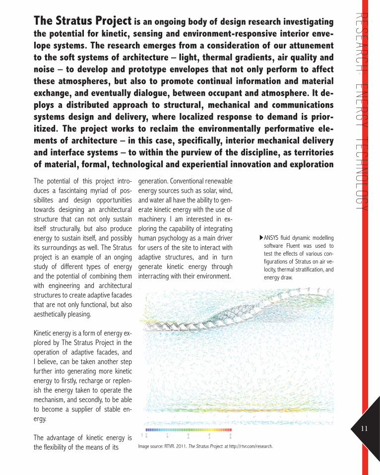
ANSYS fluid dynamic modelling software Fluent was used to test the effects of various con-figurations of Stratus on air ve-locity, thermal stratification, and energy draw.
The Stratus Project is an ongoing body of design research investigating the potential for kinetic, sensing and environment-responsive interior enve-lope systems. The research emerges from a consideration of our attunement to the soft systems of architecture – light, thermal gradients, air quality and noise – to develop and prototype envelopes that not only perform to affect these atmospheres, but also to promote continual information and material exchange, and eventually dialogue, between occupant and atmosphere. It de-ploys a distributed approach to structural, mechanical and communications systems design and delivery, where localized response to demand is prior-itized. The project works to reclaim the environmentally performative ele-ments of architecture – in this case, specifically, interior mechanical delivery and interface systems – to within the purview of the discipline, as territories of material, formal, technological and experiential innovation and exploration
generation. Conventional renewable energy sources such as solar, wind, and water all have the ability to gen-erate kinetic energy with the use of machinery. I am interested in ex-ploring the capability of integrating human psychology as a main driver for users of the site to interact with adaptive structures, and in turn generate kinetic energy through interracting with their environment.
The potential of this project intro-duces a fascintaing myriad of pos-sibilites and design opportunities towards designing an architectural structure that can not only sustain itself structurally, but also produce energy to sustain itself, and possibly its surroundings as well. The Stratus project is an example of an onging study of different types of energy and the potential of combining them with engineering and architectural structures to create adaptive facades that are not only functional, but also aesthetically pleasing.
Kinetic energy is a form of energy ex-plored by The Stratus Project in the operation of adaptive facades, and I believe, can be taken another step further into generating more kinetic energy to firstly, recharge or replen-ish the energy taken to operate the mechanism, and secondly, to be able to become a supplier of stable en-ergy.
The advantage of kinetic energy is the flexibility of the means of its Image source: RTVR. 2011. The Stratus Project. at http://rtvr.com/research.
11
Research: En
ergy Technology

Stratus prototype responding to occupant presence.
Sensors detect temperature rise from baseline settings, they then communicate with actuator motors to rotate breathing cells to open, the cooling fans are then deployed
Render of adaptive interior fa-cade.
12
A01 DEsign Futuring

Plan and axonometric drawings showing the layers and compo-nents
The axonometric view of a 3-cell structure demonstrates reac-tion to temperature change; the plan view reveals the thick array of tensegrity structure, breathing cells, fabric mem-branes, sensors and actuators
The Stratus Project v1.0 proto-type installed, lights responding to occupancy
The first prototype mobilizes smart surfaces and responsive technologies in the develop-ment of a thick suspended ceiling that produces a light and air-based architectural environment using distributed technologies and systems to sense energy and movement flows, tempered by occupant-responsive feedback in produc-ing envelopes of intimate and collective space.
Images source: RTVR. 2011. The Stratus Project. at http://rtvr.com/research.
13

Son-O-HouseNOX: Lars Spuybroek with Chris, Seung-woo Yoo, Josef Glas, Ludovica
Tramontin, Kris Mun, Geri Stavreva, & Nicola Lammers Public artwork for Industrieschap Ekkersrijt
in collaboration with composer Edwin van der Heide Son en Breugel, The Netherlands
14
A02 DEsign Com
putation

but a responsive and adap-tive structure to human interac-tion, the music generated within the structure is influenced by the humans occupying the differ-ent spaces within the structure. As previously mentioned, the time and cost saved through the input of data and the availability of comput-er simulated experimentation not only reduces cost and saves time, but also evolutionizes evidence and performance based designing, that expands the potential of design in-dependent of physical human capa-bilities.
This is extremely unique, as it is only recently that humans moved to valuing the aesthetics of archi-tectural expression.9 To be able to communicate the imagination of the human mind through the assistance of mathematics and technology brings humanity closer to the truest expression of ideas through archi-tecture.
considering or integrating the use of computational design tools, but instead, facilitates a framework or medium that further assists and provides alternatives to precon-cieved notions of design based so-lutions that were not avaliable prior to the conception of programs or engines that process algorithms.8
Computation was a key factor in realizing and modifying the design and highly influenced the design outcome in terms of physical ap-pearance and materiality. The struc-ture was such that the requirement of flexbile and durable, when com-pred wiht the brief and options gen-erated by the programs used. This reduced cost and time allocation for experimentation with materials and structure.
The geometries in particualr bene-fited greatly from computer assisted design, as the programs allow for flexibility in shape and composition, which was integral in the design of this complex pavilion that not only required to fulfil the shape, but also it’s function as a pavilion that is not only a place of rest and leisure,
This design is realized only through the integration of computer assisted modeling and generation, as the in-spiration behind the complex geom-etry that makes up the structure can only be generated through the rep-resentation of sound waves geen-rated by algorithms programed into the computer, producing a tangible shape or illustration that translates the idea of the physical embodiment of sound into a pavilion.7
However, the computational aspect is only limited to assisting in the synthe-sis and physical generation process, as this design not only involves archi-tects, but also the help of musicians, sound engineers, and programers to realize the design.
The design considers environmental factors and was experimented upon in terms of form, however, its layout and intention is very much similar to that of a house, consisting of spaces that are larger in walkways or rooms, and smaller for less dynamic spaces, such as utilitiy areas and services. This shows that the pragmatism and logic within the design process of ar-chitectural design is not lost when
Son-O-House by NOX is located in a a large industrial park the Son-O-House is a public pavilion where visitors can sit around, eat their lunch and have meetings, surrounded by IT related companies. The structure is both an architectural and a sound installation that allows people to not just hear sound in a musical structure, but also to participate in the composition of the sound. It is an instrument, score and studio at the same time.A sound work, made by composer Edwin van der Heide, is continuously generating new sound patterns activated by sensors picking up actual movements of visitors. 6
6 Arcspace. 2002. Son-O-House by NOX. Pavilions in the Netherlands.7 Kalay, Yehuda E. 2004. Architecture’s New Media: Principles, Theories, and Methods of Computer-Aided Design .Cambridge, MA: MIT Press. p. 5-25.8 Kalay. p. 8.9 Kolarevic, Brank., 2003. Architecture in the Digital Age: Design and Manufacturing. New York; London: Spon Press. p. 3-62
15
Precedents:
Son-o-
House by n
ox

Son-O-House
Perspective of the completed structure.
Images source: NOX Architects, 2000. NOXart. at http://www.nox-art-architecture.com/NOX/Book%20Excerpts/MA.pdf
Son-O-House Skeleton Fabrication
Computer aided 2D layout of the skeletal frame, ready for print and cutting for assembly.
Son-O-House Sound Outlets
Location of sound outlets that project musical piecescompsed Edwin van der Heide, generating sounds based on the movemnet of it’s occupants.
16
A02 DEsign Com
putation

Son-O-House design process
Computer aided deisgn process and assembly.
Images source: NOX Architects, 2000. NOXart. at http://www.nox-art-architecture.com/NOX/Book%20Excerpts/MA.pdf
Son-O-House scaled model
Scaled model based off the computer generated spines to create the structural frame of the pavilion.
Son-O-House Completed in 2004
Completed pavilion with mesh cladding.
17
Precedents:
Son-o-
house by n
ox

Research Pavilion 2010: Stuttgart University
Institute of Building Structures and Structural Design – Prof. Jan Knip-pers Institute for Computational Design – Prof. Achim Menges
18
A02 DEsign Com
putation

processes. Through the use of al-gorithms, mathamatical parameters set for the computer to process in-clude the physical properties and behavior of the material.14
The conclusion of this reaearch supports the integration of design computation and materialization as a feasable invetment, a hypoth-esis that can be extended towards industrialized integration of such technology in the future.
conventional methods of approaching design. “The strips are robotically manufac-tured as planar elements, and sub-sequently connected so that elasti-cally bent and tensioned regions alternate along their length. “12, evidence of futher integration of computer aided design in the fabri-cation process. The fabrication and design of 80 different strip patterns constructed from more than 500 geometrically unique parts, with the entire structure, of a diameter of more than twelve meters, can onlu be constructed using 6.5 millime-ter thin birch plywood sheets, very specfically further cites the signifi-cance of computation in the simula-tion stages via parametric modeling to reduce the waste of resources towards building the structure.
Brady theorizes about the signifi-cance of the role of computers in the field of practical architecture, whereby the gravity of it’s signifi-cance is a fact that can be extrapo-lated from this case study, as the demonstration of the capabilities of computer simulation in the design, simulation and fabrication
This structure experimented with ma-terial specific, computational design, structural simulation, and production processes in architecture. The result is entirely made of extremely thin, elastically-bent plywood strips, creat-ing a bending-active structure.
The material used was specifi-cally chosen to allow for stress and rpessure testing, both internal and externally exerted pressures. The limitation is that computer aided de-sign processes are usually unable to reflect these intricate relations, in contrast to the physical world, exper-imentation is often the conventional method of doing so. In computational design, form and force are viewed independently, as they are divided into processes of geometric form generation and subsequent simula-tions influenced by specific material properties, this is known as scripting culture.11
The computational generation of this form is directly influenced and purely synthesized by physical properties and material composition of the ply-woodstrips, evidence of an experi-mental approach to design with the intention of studying material, versus
Research Pavilion 2010 - Stuttgart UniversityIn 2010, the In-stitute for Computational Design (ICD) and the Institute of Building Structures and Structural Design (ITKE) designed and constructed a temporary research pavilion. The innovative structure demonstrates the latest developments in material-oriented computational design, simulation, and production process-es in architecture. The result is a bending-active structure made entirely of extremely thin, elastically-bent plywood strips. 10
10 Archimmenges. 2010. ICD/ITKE Research Pavilion 2010. PProf. Achim Menges: ICD Universitat Stuttgart. [http://www.achimmenges.net/?p=4443]11 Definition of ‘Algorithm’ in Wilson, Robert A. and Frank C. Keil, eds.1999. The MIT Encyclopedia of the Cognitive Sciences. London: MIT Press. p. 11, 1212 Archimmenges. 2010. 13 Peters, Brady. 2013. Computation Works: The Building of Algorithmic Thought, Architectural Design, 83, 2, pp. 08-1514 Archimmenges. 2010.
19
Precedents: ICD/ITK
E Research Pavil
ion 2010
Stuttgart University
Images source: Institute for Computational Design. 2010. ICD/ITKE Research Pavilion 2010. at http://icd.uni-stuttgart.de/?p=4458
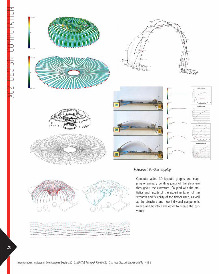
Research Pavilion mapping
Computer aided 3D layouts, graphs and map-ping of primary bending joints of the structure throughout the curvature. Coupled with the sta-tistics and results of the experimentation of the strength and flexibility of the timber used, as well as the structure and how individual components weave and fit into each other to create the cur-vature.
20
A02 DEsign Com
putation

Joint Detailing
Close up of joints at the base of each end of the timber weaving within the structure.
Images source: Institute for Computational Design. 2010. ICD/ITKE Research Pavilion 2010. at http://icd.uni-stuttgart.de/?p=4458
Research Pavilion asembly
Construction and completed structure. Details of the weaving ma-terials are also called out.
21
Precedents: ICD/ITK
E Research Pavil
ion 2010
Stuttgart University

Research Pavilion 2010: Stuttgart University
Institute of Building Structures and Structural Design – Prof. Jan Knip-pers Institute for Computational Design – Prof. Achim Menges
Son-O-HouseNOX: Lars Spuybroek with Chris, Seung-woo Yoo, Josef Glas, Ludovica
Tramontin, Kris Mun, Geri Stavreva, & Nicola Lammers Public artwork for Industrieschap Ekkersrijt
in collaboration with composer Edwin van der Heide Son en Breugel, The Netherlands
Images source: Institute for Computational Design. 2010. ICD/ITKE Research Pavilion 2010. at http://icd.uni-stuttgart.de/?p=4458
Images source: NOX Architects, 2000. NOXart. at http://www.nox-art-architecture.com/NOX/Book%20Excerpts/MA.pdf
22
A03 Composition Generation

Figure 1Conceptual design model of the Son-O-House, pre-digitization.
Figure 2Computer generated graphs that depict stress levels within the components in different forms.
15 Arcspace. 2002. 16 Archimmenges. 2010. 17 Archimmenges. 2010.
the parameters of computational design. This is evidenced through the Research Pavilion, whereby the form is generated based on the physical properties of its material-ity, plywood.16
The function of the Research Pavil-ion as an experiment of material-ity, allowed for the emergence of a complex, weaving design. This was only made possible through the use of computational design to extrap-olate physical forms based on pre-exiting data and experimentation of the material, as seen in Figure 2.
it’s structure for fabrication, how-ever, the disadvantage of doing so is evident through the loss of the desired organic forms seen in the conceptual design. This is due to the pre-existing limitations set by the programing of the computation-al design softwares, a necessary sacrifice in terms of programming to be able to create the software. This limitation highlights the dispar-ity of the creativity of the human mind from the tools which are the computer programs.
This disparity, however, is chal-lenged by Oxman (2014), whom claims that such limitations enable architects and desingers to explore other possibilities of design within
These two projects consider two dif-ferent ways of using computational design within the design process.
In Son-O-House, computaiton desgin was crucial in achieving the form of the skeletal frame that holds up the mesh of the structure. In contrast, the Research Pavilion’s design was integral in the simulation of material resilience, which in turn allowedfor the emergence of the final design.
This contrast is a fascinating parallel in regards to the use of computa-tional designing. One of which uses it as a medium for composition, while the other for generation.
Conceptually, the Son-O-House be-gan with a more organic and fluid strcture, as seen in figure 1, however, it is not physically possible to achieve such curvature. The integration of computational design gave the de-signers a digitized version of the paper scale model in its smoothest form, and provided anchor points for each curvature, hence creating “in-terlacing vaults that sometimes lean on each other or cut into each other” in order to create the final design. 15
The advantage of this apporach was being able to manipulate the existing design to become more realistic in
Son-O-House by NOX & Research Pavilion 2010 - Stuttgart University as precedents, both make use of computational aid to generate designs towards realizing proposed designs. Both precedents have been com-pleted and are tangible examples of successful structures that relied heavily on algorithmic thinking, parametric modelling and scripting culture to achieve the deign intent.
These two parallels make use of computational design as a tool to compose as well as generate de-signs. Although this method has limitations, the parameters can also be exploited to create different de-sign outcomes of a more tangible and realistic quality. 23
Precedents: Gen
erative approaches

The videos have helped tremendously in the understanding the basics and logic of Rhino. Here is a pictorial documen-tation of progress over the last 3 weeks based on the prescribed videos.
24
A04 Appendix and algorithmic sketches

AppendixArchimmenges. 2010. ICD/ITKE Research Pavilion 2010. PProf. Achim Menges: ICD Universitat Stuttgart. [http://www.achimmenges.net/?p=4443]
Arcspace. 2002. Son-O-House by NOX. Pavilions in the Netherlands.
Bishop, et.al. 2012. The Canopy. Land Art Generator Initiative Competition 2012.
Definition of ‘Algorithm’ in Wilson, Robert A. and Frank C. Keil, eds.1999. The MIT Encyclopedia of the Cognitive Sciences. London: MIT Press. p. 11, 12
Fry. 2009. Design Futuring: Sustainability, Ethics, and New Practice. Oxford: Berg Publishers.
Institute for Computational Design. 2010. ICD/ITKE Research Pavilion 2010. at http://icd.uni-stuttgart.de/?p=4458
Kalay, Yehuda E. 2004. Architecture’s New Media: Principles, Theories, and Meth-ods of Computer-Aided Design .Cambridge, MA: MIT Press. p. 5-25.
Kolarevic, Brank., 2003. Architecture in the Digital Age: Design and Manufactur-ing. New York; London: Spon Press. p. 3-62
NOX Architects, 2000. NOXart. at http://www.nox-art-architecture.com/NOX/Book%20Excerpts/MA.pdf
Oxman, Rivka and Robert Oxman, eds (2014). Theories of the Digital in Architec-ture (London; New York: Routledge), pp. 1–10
Peters, Brady. 2013. Computation Works: The Building of Algorithmic Thought, Architectural Design, 83, 2, pp. 08-15
RTVR. 2011. The Stratus Project. at http://rtvr.com/research.
Schumacher. 2011. The Autopoiesis of Architecture. A New Framework for Archi-tecture. John Wiley.
Thomas & Vince-Prue. 1996. Photoperiodism in Plants. 2nd Edition. Academic Press.
25
Appendix an
d Algorith
mic
Sketch
es


Part B Criteria Design

Spanish Pavilion, Expo 2005, Aichi, Japan Foreign Office Architects
Images source: Digital Architecture Fabrication. 2005. Spanish Pavilion 2005 at http://digiitalarchfab.com/portal/wp-content/uploads/2012/01/Spanish-Pavilion.pdf
28
B01 Research Field

BIOMIMICRY IS ABOUT HUMAN SOCI-ETY LEARNING FROM IT’S NATURAL ENVIRONMENT AND INTEGRATING SYSTEMS AND SOLUTIONS TO BUSI-NESSES AND TECHNOLOGY. Nature, as a teacher, not only serves as a useful mentor for problem solving, but also an ecological standard for justifying and valuing innovation: from function, to durability, and to suitability.2
Biomimicry in architecture is often difficult to replicate due the organic and complex construct of natu-rally existing structures. Man-made technology that exists today is not advanced enough to be able to ac-curately construct the curvature and joints that share both, aesthetic and functional traits.
The individual hexagonal units were designed and produced in Spain, hence replicating them using soft-ware such as Rhino and Grasshopper based on pre-set algorithms proved complex, even with the simple geom-etry as a base shape, such as the hexagon.
Iterations were generated based on the algorithm provided and were rep-licated.
Spanish Pavilion, Expo 2005 by Foreign Office Architects replicates traditional lattice windows on external walls, inspired by the struc-ture and compactness of honeycombs, to diffuse the distribution of light and protecting the interior spaces from wind and rain.1 Inspired both by Spanish culture and naturally existing systems, FOA is an example of architects utiliz-ing scientific knowledge of nature and combining the human experience to create a unique architectural experience for its users.
1 Ceramic Architectures. 2005. Spanish Pavilion Expo 2005. Obras.2 Visser, Wayne, & Benyus, Janine M. . 2009. Biomimicry. The Top 50 Sustainability Books. Greenleaf Publishing & GSE Research. p. 104-107 (4).3 Ceramic Architectures. 2005.
Figure 1Site location, perspective projec-tion, plans, elevation and section of the Spanish Pavilion at the 2005 Expo, in Aichi, Japan.3
29
Biomimicry
The Morning Line, Vienna Thyssen-Bornemisza Art Contemporary
Images source: Thyssen-Bornemisza Art Contemporary. 2011. The Morning Line, Vienna at https://www.flickr.com/photos/thyssen-bornemisza_art_contemporary/
30
B01 Research Field

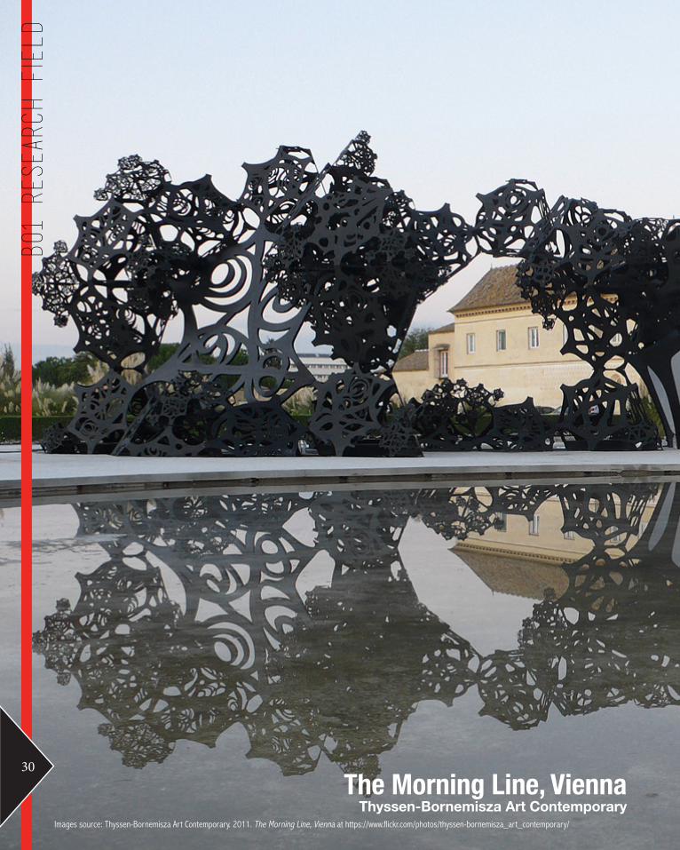
The structure of the pavilion was based on the idea of geometric frac-tals, recursive and repetitive by defi-nition, and can be joined to each oth-er to generate the final product. The Morning Line was realized through using an equilateral tetrahedron and truncating fractal processing tech-niques.
This was a complex process made possible through the use of pro-grams to not only enhance creative boundaries, but also facilitate the probability of physically fabricating the structure. The completed struc-ture was created and utilized as a performance space for musicians and composers.6
Paul Steinhardt and Neil Turok’s cos-mology theories led to the develop-ment of the visually engaging design and buildable cellular structure, with the resounding quote: “evolution of the universe as a story without begin-ning or end, only movement around multiple centers.” A clear connection between biomimicry in architecture.7
Iterations were generated based on the algorithm provided and were rep-licated.
The Morning Line, Vienna 2011 by Aranda\Lasch integrates architecture with physically intangible sensations through working together with other disciplines, such as music, as well as other faculties such as art, mathematics, cosmology and science.4 Intergating biomimicry and computa-tional design and challenging existing techniques, Aranda\Lasch worked in collaboration with Matthew Ritchie and Arup Advanced geometry unit to real-ize this semiasographic building - directly expressing content through struc-ture.5
4 Choi, Leeji. 2009. The morning line by Matthew Ritchie with Aranda\Lasch and Arup. Design Boom at http://www.designboom.com/art/the-morning-line-by-matthew-ritchie-with-aranda-lasch-and-arup/.5 Siggraph. 2008 .The morning line. Siggraph at http://www.siggraph.org/s2009/galleries_experiences/generative_fabrication/04.php3 Ceramic Architectures. 2005.6 Choi. 2009.7 Thyssen-Bornemisza Art Contemporary. 2008. Matthew Ritchie with Aranda\Lasch and Arup AGU – The Morning Line. Thyssen-Bornemisza Art Contemporary at http://www.tba21.org/pavilions/49/page_2?category=pavilions.
Figure 2Computer generated projections of the structure and photograph of the structure onsite. IS
31
Biomimicry

VoltaDom Installation Skylar Tibbits and SJET
Images source: SJET. 2011. Voltadom: MIT 2011. SJET at http://www.sjet.us/MIT_VOLTADOM.html.
32
B01 Research Field

Voronoi, in the study of biomimicry, was the inspiration behind the fab-rication of the vaults that divide the spaces into regions based on speci-fied points along an allocated matrix. This created the layout of the vaults, which emerged into the passageways while providing thickened surface ar-ticulation. At the center of the vaults, the oculi allows for light penenetra-tion and unique views for its users.10
The surface panels were also further developed towards multiple curves within vaulted surfaces. The resulting geometry creating intricate and al-most natural “curves within curves”. 11
The realization of this design re-quired the simplifying of this design into strips of material that can be easily fabricated. This method allows for design limitatons to be challenged to go beyond exisiting parameters, and allows for the realization of hy-birdized designs that are not only accurate to the imagination but also easy to fabricate.
Iterations were generated based on the algorithm provided and were rep-licated.
VoltaDom Installation by Skylar Tibbits and SJET reflects the marriage of multidisciplinary research and parametirc design.8 The structure stands as a vaulted passageway with rib vaulted ceilings, as a contemporary design that pays tribute to iconic features in architectural history.9
8 Grozdanic, Lidija. 2011. VoltaDom Installation / Skylar Tibbits + SJET. eVolvo at http://www.evolo.us/architecture/voltadom-installation-skylar-tibbits-sjet/.9 Grozdanic. 2011.10 SJET. 2011. VoltaDom: MIT 2011, SJET at http://www.sjet.us/MIT_VOLTADOM.html. 11 SJET. 2011.
Figure 3Experiencing the Voltadom Installation fromt he inside.
Photocredits: SJET.us
33
Biomimicry

Aperture:0.5 units offset from curve.
Aperture:1.0 units offset from curve.
Aperture:1.5 units offset from curve.
Height:Varied gradients of heights from uniformed to random.
The primary varibales that were altered in these iterations were limited to their height and apetures to show the varia-tions possible of a single geometric form aka the hexagonal basic shape.
34
B02 Case Study 1.0
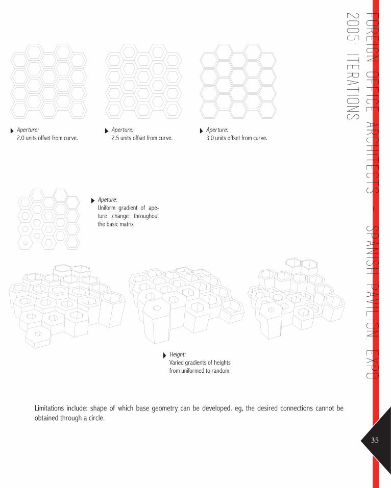
Aperture:2.0 units offset from curve.
Aperture:2.5 units offset from curve.
Aperture:3.0 units offset from curve.
Height:Varied gradients of heights from uniformed to random.
Apeture:Uniform gradient of ape-ture change throughout the basic matrix
Limitations include: shape of which base geometry can be developed. eg, the desired connections cannot be obtained through a circle.
35
Foreign Office Arch
itects - Span
ish Pavil
ion, Expo
2005: ITERATIONS

Fractals: 3.1 units
Fractals: 4.1 units
Fractals: 5.1 units
Fractals: 3.4 units
Fractals: 4.4 units
Fractals: 5.4 units
Fractals: 3.2 units
Fractals: 4.2 units
Fractals: 5.2 units
Fractals: 3.3 units
Fractals: 4.3 units
Fractals: 5.3 units
The definition is altered through changing the size of the polygons via the radius and number of sides of the geometry in Grasshopper.
Sliders determine the number of fractals on the polygon, Increasing the number of fractals generate increasingly complex forms as seen above.
36
B02 Case Study 1.0

Fractals: 7.1 units
Fractals: 8.1 units
Fractals: 6.1 units
Fractals: 7.4 units
Fractals: 8.4 units
Fractals: 6.4 units
Fractals: 7.2 units
Fractals: 8.2 units
Fractals: 6.2 units
Fractals: 7.3 units
Fractals: 8.3 units
Fractals: 6.3 units
Limitations include: the inversely proportional ploygons to the extrusion points in the x-axis. This resulted in the flat tening of the 3D objects formed.
37
Aranda\
Lasch
- Th
e Morn
ing L
ine: Iteration
s

Points of ConesHe
iight
of C
ones
Radius of ConesRa
dius
of C
ones
Voronoi are generated through the intersection of cones with a single plane along the x-axis that trim off the cone tip, and in turn creaing an oculus.
The variables include: cone heights, oculi diameter, and number of cones.
Position of points in the parameter can also be randomly positioned throughout the selected space
38
B02 Case Study 1.0

Limitations include:the extent to which the geometires can be modified until they no longer represent voroni
39
Skylar Tibbits an
d SJET -
VoltaDom
INstal
lation
2011: ITERATION
S

Nonlin/lin PavilionMarc Fornes and Theverymany
Images source: Theverymany. 2011. Nonlin/lin Pavilion at http://theverymany.com/constructs/10-frac-centre/
40
B03 Case Study 2.0

Figure 4Process of fabrication. Photo credits to thevery-many.
This prototype experiments in text based morphologies and custom comuptational pro-tocols. Parameters include: - Form finding (surface relaxation)- Form description (composition of linear elements)- Information modeling (re-assembly data)- Generational heirarchy (distributed networks)- Digital fabrication (logistic of pro-duction) 13
The scale is able to be varied in vari-ous productions, coupled with mate-rials that are extremely resilient to loads, and is straightforward to as-semble.
The technology used to generate this structure include Robert McNeel & Associates (Rhino3D), TDM Solutions (RhinoNest), and VRay (for Rhino).
The different properties are generat-ed with different properties through many types of agent behaviors, in order to generate forms of radically different morphologies and achieve the stability and aesthetic required of this structure.14
nonLin/Lin Pavilion by Marc Fornes & Theverymany is an ex-ample of computational design that addresses and challenges the issue of creating desings “from network to surface condition” and “from non-linear morphology to descriptive geometrical search into linear elements”.12 Through the use of computational design, the inspiration of coral is brought to life through this structure through paneling, the simplest form of fabrication that alludes to the complexities of architecture that is influenced by biomimicry. This was a sucessful experiment in addressing these issues.
12 Theverymany. 2011. 11 Frac Center. nonLin/Lin Pavilion at http://theverymany.com/constructs/10-frac-centre/13 Theverymany. 2011.14 Theverymany. 2011.
41
Marc forn
es and th
everymany -
NONlin/lin pavil
ion
2011

i
ii
iii
iv
v
1. As an initial experimentation of an arch form which has the tubes that are similar to the NonLin Pavilion us-ing rhino, circles were drawn to generate the desired form. Angles of these circles are varied in order to create the specific form and provide the variation and increase the complexity of the structure to that of the case study.
42
B03 Case Study 2.0

2. After the circles were generated, they were lofted using grasshopper. It was proved quite difficult to recreate the “puckering” effect of the tubes at the ends of the openings, as well as the seemingly smooth joints of the tube forms where they intersect. As a result, this solution was abandoned and a different approach was attempted, as advised through the technical help session. 43
Marc forn
es and th
everymany -
NONlin/lin pavil
ion
2011: REVERSE ENGIN
EERING

1. Through analyzing the idea of creating a tri-partite form and circulation pattern of the NonLin Pavilion, the current shape being re-engineered is based on the “Y” form, similar to that of the precedent. Generating lines on rhino in this manner creates the inhabitable space in which the visitors can explore inside. 2. These lines are then joined in a logical manner as an attempt to create variation and increase the complexity of the form while creating an almost arch like shape. Furthering this, there are added lines which extrude from the initial arches to try and create more “branches” for the tubes.
i
ii
iii
iv
v
44
B03 Case Study 2.0

3. The use of grasshopper and kangaroo was integral in creating the exoskeleton structure of the form as it takes the curve inputs from rhino and creates a base mesh. From the exoskeleton component, there is the op-portunity to vary the sides, thickness, nodes, knuckle bumpiness and division length along the tubes. The result is a mesh which is further explored in the next step.4. Using the mesh, the forces for relation can be altered according to the nodes to create a physics simu-lation using the Kangaroo plugin. It uses the points around the exterior edges as anchors in order to make the interior edges into “springs”. By incorporating a slider, you can change the mesh to more or less relaxed (varying the length of the springs by the original length). By using this function, the final outcome creates a more funnel like tube which is similar to the pavilion.
45
Marc forn
es and th
everymany -
NONlin/lin pavil
ion
2011: REVERSE ENGIN
EERING

62930.40.030.0OFF
Sides for tubes > Thickness > Node Size > Knuckle > Spacing > Boolean
310.00.00..9OFF
340.00.010.0OFF
6112.80.030.0OFF
567020.40.5
101912.810.02.4OFF
6112.80.030.0OFF
101928.710.030.0OFF
10125.01030.0OFF
8906.120.40.5
46
B04 Technique: Development

Sides for tubes > Thickness > Node Size > Knuckle > Spacing > Boolean
3185.810.030.01.0
310.00.00.91.0
6112.80.030.00.0
6112.80.030.00.0
683311.10.89
10350.010.030.01.0
10224.010.030.01.0
101827.510.010.01.0
6112.80.030.01.0
567020.40.5
47
Iteration Gen
eration
8906.120.40.5
Sides for tubes > Thickness > Node Size > Knuckle > Spacing > Boolean
81310.80.016.2TRUE
313.71.1300.5
911130.016.8TRUE
11.00.78.0TRUE
683311.10.89
101720.50.012.2TRUE
72.54.52300.5
81310.80.016.2TRUE
71010.345FALSE (0%)
48
B04 Technique: Development

Sides for tubes > Thickness > Node Size > Knuckle > Spacing > Boolean
72.54.523.0.5
101720.50.012.2FALSE (0%)
7252.5270.89
10712.85.110.1TRUE
313.603.1TRUE
7252.5270.89
3107.7013.3TRUE
313.71.1300.5
447.60.020TRUE
320.00.015.1TRUE
49
Iteration Gen
eration
1080.00.030FALSE (0%)
4
10114.7030FALSE (0%)
Aura tally
567020.40.5
1085030FALSE (0%)
10
10114.7022FALSE (20%)
10125.01030.0OFF
8906.120.40.5
Sides for tubes > Thickness > Node Size > Knuckle > Spacing > Boolean
50
B04 Technique: Development

15 Kalay, Yehuda E. (2004). Architecture’s New Media: Principles, Theories, and Methods of Computer-Aided Design (Cambridge, MA: MIT Press), pp. 5-2516 Kalay. (2004)
Based on the brief given, our selection criteria con-sidered the significance of the structure being able to harness energy via capturing energy i.e. wind on site.
Additionally, we wanted to ensure that the structure would be relevant and appropriate within the context of the site, blending it with its current surroundings but at the same time, being able to stand out with its unique composition to attract users. All while remain-ing unique to the site and its heritage.
Following our initial research field of biomimicry, we attempted to generate potential designs that could micmic systems that exist in the natrual surroundings of the site. It also had to be an interesting space for users to occupy through evoking curiousity and inter-est from visitors who would then be drawn to interact with the space.
The tubular forms from the nonLin/Lin Pavilion were thus adapted and further developed through explor-ing different shapes, sizes and combinations, each in-creasing in complexity, while ensuring that it retained the ability to capture sufficient wind to produce energy. It was also essential to further incorporate the histori-cal, social and cultural context when considering the design.
Kalay states “search(ing)” comprises of “Finding or developing candidate solutions, and evaluating them against the goals and the constraints” .15 The process involves produces a series of potential solutions, and then selecting the most appropriate one to further evaluate and develop. It is crucial to ensure that each iteration is thoroughly reviewed on the premise of ful-filling the selection criteria. As specified in the reading, search methods should abide to the following: Depth first, Breadth first and Best first.16 Through following these rules, we were able to explore each iteration
thoroughly and shortlist the most promising options with the most potential for further development.
The selection criteria for our group is ranked as fol-lows:- Functionality of the space and the structure - Buildability and realization of project - Harness energy via use of wind - Aesthetics Relation to the site - Relating back to the ideas of biomimicry - Use of materials - Consideration of users and creating a space for them - to occupy - Affect and effect - Light and shadow, creating an emotive response
Iteration 50 was the most successful iteration of the set. The desing potential fits witht he aesthetic and function listed in the selection criteria lined up by the group. It’s geometries allow for both functional usage (eg as a pavilion) as well as present members that have potential energy harnessing capabilities.
In PROTOTYPES, a single member of this iteration is chosen for prototype testing.
51
Iteration Gen
eration

PanelingPanels distributed throughout the memember for fabrication. Panels are laid out such that they can be exploded into smaller panels and rejoined into strips for printing, cutting and assembly.
52
B05 Technique: Prototypes

PanelingUnrolled panels in preparation for fabrication, accom-pained by the exploded model of the overall structure.
Paneling is a method of fabricating struc-tures that can emulate organic or almost organic shapes while using solid materials, eg. metals. In-dividual panels are fabricated and joined togeter to make a shape or a face of the structure.
This prototype was digitally modeled and laid out using Rhino and Grasshopper.
However, it was quickly revealed through the software that the generated member of the iteration had corners and edges that were unsuitable for the desired outcome. These errors and complex joints are highlighted in red on the right.
It was with this revelation that forced the group to move on to our second prototype.
53
prototyping: Prototype 0

Metal and FabricMetal wires representing studs and reinforcement to the fabric and as support to assist in realizing the intended shape of thestrcture through the versatile and flexible fabric.
54
B05 Technique: Prototypes

Digital model and pre-fabricated joint members Counterclockwise from left are the digital models in various states of progress, followed by the pre-fab joint members printed and cut from MDF
Testing outcomesResults indicate that the strcutre is weak in terms of overall structurall support with relatively durable isolated members.
SolutionsAdd additional supports along the horizontal and vertical plane of the structure to ensure the forces are evenly distributed throughout the structure.
Construct more secure joint systems to hold memebers together without adhesives.
Metal and Fabric is another method we pursued. With prefabricated (built in Rhino and lazer cut) joints to hold the metal wire together to act as the steel supports and reinforcements for the structure. This prototype is Prototype 1.
However, it was quickly revealed through model making that the amount of sup-ports we fabricated were insufficient to hold up the entire structure due to dead loads. Also, the intgeration of fabric with the metal wires proved more challenging that expected, and resulted in a more complex aesthetic, an emer-gence that we may consider keeping for the final design.
It was after these revelations that the group to move on to our third prototype.
55
prototyping: Prototype 1

Timber and FabricTimber stud framing used as the primary support system with layered fabric and as cladding to assist in realizing the intended shape of thestrcture through it’s versatility, in turn facilitating the emergence of a more complex and textured outcome.56
B05 Technique: Prototypes
Timber stud framingDigital model of the proposed timber stud framing from various views before being fabricated physically.
Testing outcomesResults indicate that the strcutre is relatively strong in terms of overall structurall support with relatively durable isolated members.
SolutionsConsider more secure and more practical fabrication solutions for con-structing the model at 1:1 scale.
Design a structural support system that would connect the earth to the structure.
Timber and Fabric is the final method we pursued. With more traditional meth-ods and materials, we consdiered the possibility of using timber stud framing to be the primary support for the structure. This prototype is Pro-totype 2.
After construction, it became apparent that the structure has difficulty standing on it’s own un-less on different angles or slanted on an even surface. While it can support it’s own weight, it has not direct footings holding it to the ground.
The use of timer studs proved most sturdy, while being able to carve out the shapes required.
Although this was the most sturdy physical model, the methods used to construct the model would be inappropriate at a larger or 1:1 scale, and hence rquires more refinement.
57
Prototyping: Prototype 2
COPENHAGEN
AERIAL PHOTOS OF REFSHALEØENIMAGE SOURCE: HTTP://LANDARTGENERATOR.ORG
1
2
1. LAND ART GENERATOR INITIATIVE LOCATION (LAGI)2. LAGI 2014 COMPETITION LOCATION PLAN
MARITIME
HISTORICAL PHOTOS OF REFSHALEØENIMAGE SOURCE: REFSHALEØEN HOLDING
The brief was to design a sculpture or building that can generate or create energy. Site location is highlighted in Co-penhagen’s Land Art Generator Initiative site. The location of the site was historically a port and harbor for industrial purposes. To reference it’s history, we deiced that “Time” was going to be one of the key drivers in determining the structures design.
Based on this research, we drew inspiration from an existing iconic sculpture, The Little Mermaid, as well as the ma-terials that exist wihtin the site: metal (that corrodes over the course of time), clay bricks, and timber.
58
B06 Technique: proposal
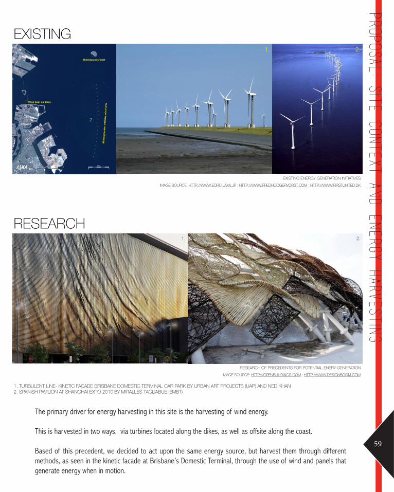
EXISTING
EXISTING ENERGY GENERATION INITIATIVESIMAGE SOURCE: HTTP://WWW.EORC.JAXA.JP ; HTTP://WWW.FREDHOOGERVORST.COM ; HTTP://WWW.FIRSTUNITED.DK
1. 2.
1
2
RESEARCH
RESEARCH OF PRECEDENTS FOR POTENTIAL ENERY GENERATIONIMAGE SOURCE: HTTP://OPENBUILDINGS.COM ; HTTP://WWW.DESIGNBOOM.COM
1. TURBULENT LINE- KINETIC FACADE BRISBANE DOMESTIC TERMINAL CAR PARK BY URBAN ART PROJECTS (UAP) AND NED KHAN2. SPANISH PAVILION AT SHANGHAI EXPO 2010 BY MIRALLES TAGLIABUE (EMBT)
1. 2.
The primary driver for energy harvesting in this site is the harvesting of wind energy.
This is harvested in two ways, via turbines located along the dikes, as well as offsite along the coast.
Based of this precedent, we decided to act upon the same energy source, but harvest them through different methods, as seen in the kinetic facade at Brisbane’s Domestic Terminal, through the use of wind and panels that generate energy when in motion.
59
proposal: Site con
text and en
ergy harvestin
g
60
B06 Technique: proposal
1. 2.
3.
4.
5.
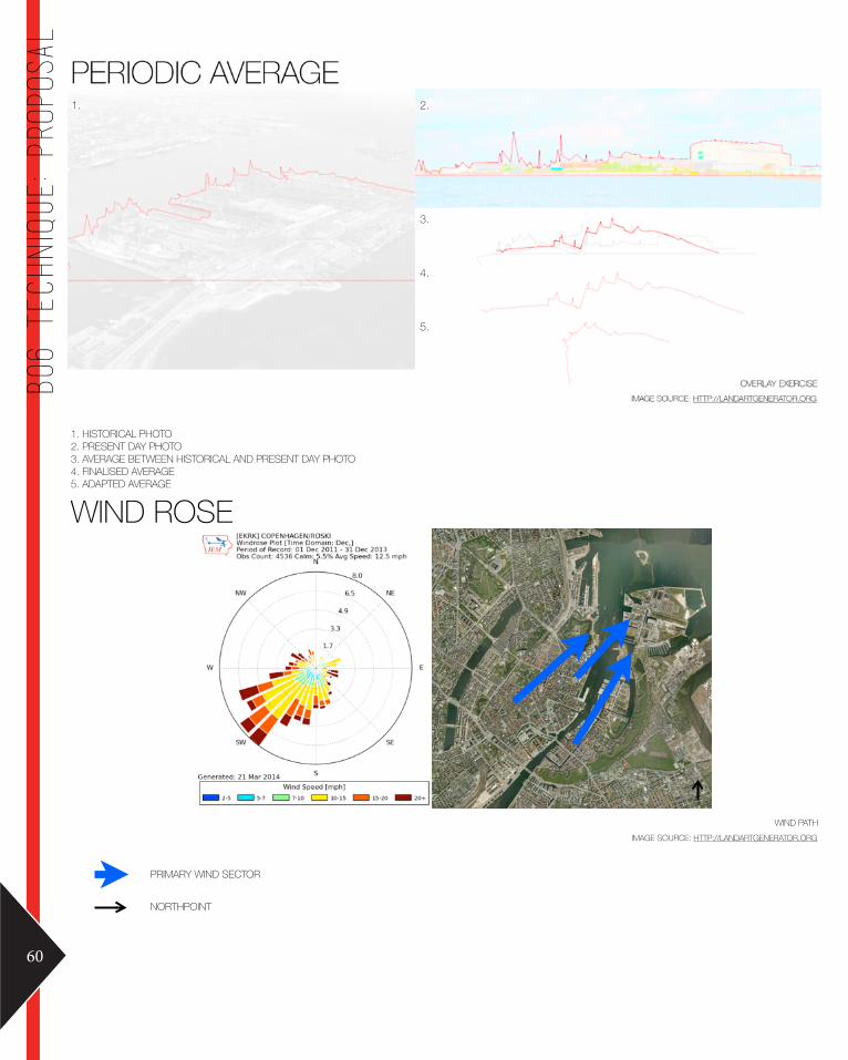
1. HISTORICAL PHOTO2. PRESENT DAY PHOTO 3. AVERAGE BETWEEN HISTORICAL AND PRESENT DAY PHOTO4. FINALISED AVERAGE 5. ADAPTED AVERAGE
WIND ROSE
WIND PATH IMAGE SOURCE: HTTP://LANDARTGENERATOR.ORG
PRIMARY WIND SECTOR
NORTHPOINT

Other factors that influenced the final design include taking data that are foudn to surround or even create the site. We plotted a landscape based on historical and present day photos of the site, and form their intersecting points, generated a new data path that symbolizes the unification of the history of the site as well as the present day, a tribute to what has been and what is.
The height of the structure was determined when comparing the structure to the windrose diagram, whereby the members with strongest wind velocity, called for a higher structure to be placed as an opportunity to harvest higher amounts of energy. Also, at higher heghts, the higher the velocity of wind travels, therefore a tall design has potential to harvest more energy when positioned strategically.
Biomimicry was the precedent studied previously, and its complexity aids in the realization of the organic design that we hope to achieve. The materials we explored, as mentioned prior, are referenced from the historical features of the site, and integrated into the contemporary context.
61
proposal: Form
generation
- in
fluen
cing factors
BIOMIMICRY
NONLIN/LIN PAVILION BY MARC FORNES THE VERY MANIMAGE SOURCE: HTTP://WWW.DEZEEN.COM
2
HISTORICAL AND EXISTING
HISTORICAL AND EXISTING MATERIALS
RESEARCH
EXISTING ENERGY GENERATION INITIATIVESIMAGE SOURCE: HTTP://WWW.EORC.JAXA.JP ; HTTP://WWW.FREDHOOGERVORST.COM ; HTTP://WWW.FIRSTUNITED.DK

PERSPECTIVE TOP
PROPOSED DESIGN INSPIRED BY WIND ROSES
FRONT
PROPOSED DESIGN INSPIRED BY WIND ROSES
PROPOSED MINIMUM HEIGHT OF APPROXIMATELY 4M
The finalized form for the preliminary submission is as above
The structure combines sculptural and pavilion like elements that create an interesting and functional open space for people to interract with and explore.
The proposed minium height is 4m, for the exact purposes as stated previously.
62
B06 Technique: proposal

RHIN GRASSHOPPE EXOSKELETO WEAVERBIR KANGARORHINO GRASSHOPPER EXOSKELETON WEAVERBIRD KANGAROO
These diagrams is the generated linework created through the process as stated on TOP: Proposed algorithmic deisgn method.
The linework diagram on the TOP LEFT: the plotted lines from the top view without the exoskeleton plugged in.
The remaining diagrams is the linework of the finalized model taken from different views.
63
proposal: FIn
alized design

PLAN VIEW
PRIMARY VIEWS TO THE LITTLE MERMAID STATUE ACROSS THE WATER
LOCATION OF PROPOSED DESIGN
AERIAL PHOTOS OF REFSHALEØENIMAGE SOURCE: HTTP://LANDARTGENERATOR.ORG
64
B06 Technique: proposal

PLAN VIEW
PRIMARY VIEWS TO THE LITTLE MERMAID STATUE ACROSS THE WATER
LOCATION OF PROPOSED DESIGN
AERIAL PHOTOS OF REFSHALEØENIMAGE SOURCE: HTTP://LANDARTGENERATOR.ORG
65
proposal

PLAN VIEW
VIEWS AND CIRCULATIONIMAGE SOURCE:HTTP://LANDARTGENERATION.ORG
PRIMARY VIEWS TO THE LITTLE MERMAID STATUE ACROSS THE WATER
SECONDARY VIEWS
PRIMARY CIRCULATION PATHWAY66
B06 Technique: proposal

PLAN VIEW
VIEWS AND CIRCULATIONIMAGE SOURCE:HTTP://LANDARTGENERATION.ORG
PRIMARY VIEWS TO THE LITTLE MERMAID STATUE ACROSS THE WATER
SECONDARY VIEWS
PRIMARY CIRCULATION PATHWAY67
proposal: sim
plified pl
an view

ON SITE
SITE PHOTOS OF REFSHALEØENIMAGE SOURCE: HTTP://LANDARTGENERATOR.ORG
ARCHITECTURAL ELEMENTS TO CONSIDER:
RHIN GRASSHOPPE EXOSKELETO WEAVERBIR KANGARORHINO GRASSHOPPER EXOSKELETON WEAVERBIRD KANGAROOLIGHT ORGANIC FORM SLENDERNESS MATERIALITY LAYOUT68
B06 Technique: proposal

ON SITE
SITE PHOTOS OF REFSHALEØENIMAGE SOURCE: HTTP://LANDARTGENERATOR.ORG
LIGHT: Playing with shadows and light through the gaps between the different members to capture different views.ORGANIC FORM: A tribute to biomimicry as a study while remaining unique to the site.SLENDERNESS: To ensure a steamlined asthetic that can also be fabricated easily.MATERIALITY: Must be lightweight to be able to suatin dead loads as well as environmental loads, eg. winds, com-pression, tension, and movement.LAYOUT: Freeform/open planned layout that is meant to generate intrigue and the sense of curiosity to explore the strcuture while being directed through the arches to exit towards the main views.
69
proposal: Ren
dered view

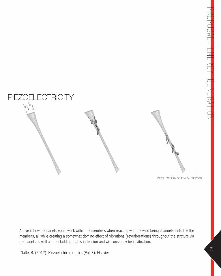
PIEZOELECTRICITY
PIEZOELECTRICITY GENERATION PROPOSALIMAGE SOURCE: HTTP://WWW.AZOM.COM ; HTTP://WWW.FREDHOOGERVORST.COM ; HTTP://WWW.FIRSTUNITED.DK
Piezoelectricity is the generation of electric charges that are proportional to mechanical stress by specific crystalline materials.17
The potential here combined with the intensity of wind velocity onsite allows fortremedous potential for piezoelectricity to be used as an efficient energy harvester.
70
B06 Technique: proposal
PIEZOELECTRICITY
PIEZOELECTRICITY GENERATION PROPOSAL
Above is how the panels would work within the members when reacting with the wind being channeled into the the members, all while creating a somewhat domino effect of vibrations (reverberations) throughout the strcture via the panels as well as the cladding that is in tension and will constantly be in vibration.
17Jaffe, B. (2012). Piezoelectric ceramics (Vol. 3). Elsevier.71
proposal: En
ergy generation
PRESENTATION FEEDBACK
GROUP 8- Materiality of the models is quite nice, but should be integrated into the definition- Very much a bit of sculpture - the inhabitation/energy generation aspect doesn’t make sense at the moment- Think about the branches or ‘members’ in your structure. Why do they look the way they do? Do they vary in thick-ness or degree of tapering?
72
B07 Learning objectives
73
Follow
up
Explore the intricacies of integrating materiality into the paneling of the digital model through integrating the appropriate definitions wihtin the software.Further practice and explore grasshopper and other plugins to achieve an accurate and develop-able 3D model.
Some programs to explore:Ecotech for testing wind levels Gecko as a grasshopper pluginMasslab to reduce the number of panels for simpler fabrication
Possible follow up steps:Estimate and average vibrations of materials and put them in Grasshopper to compare and then analyze the resultsPhysical conditions, assembly/systems and geometry of the sizeConsider wind shadows and turbulence
Expand the architectural aspects of creating a more habitable structure. Research the energy generation aspect and statstics/facts behind piezioelectricity.Explore how much energy is produced and why are the forms tapered beyond enhancing func-tionality, and explain how that works.

ALGORITHMIC SKETCHESExploration of lofting, Fields and Attracter Points, Delaunay func-tions wihtin the definitions of grasshopper was conduted through-out the design process alongside the tutorial videos throughout the weeks.
Other sketches are listed as seen throughout B02, B03 and B04, all of which utitlize these techniques and beyond. Refer to these sections for the specifications and details.
74
B08 Appendix - Algorithmic sketches

AppendixArchimmenges. 2010. ICD/ITKE Research Pavilion 2010. PProf. Achim Menges: Ceramic Architectures. 2005. Spanish Pavilion Expo 2005. Obras.
Choi, Leeji. 2009. The morning line by Matthew Ritchie with Aranda\Lasch and Arup. Design Boom at http://www.designboom.com/art/the-morning-line-by-matthew-ritchie-with-aranda-lasch-and-arup/.
Grozdanic, Lidija. 2011. VoltaDom Installation / Skylar Tibbits + SJET. eVolvo at http://www.evolo.us/architecture/voltadom-installation-skylar-tibbits-sjet/.
Jaffe, B. (2012). Piezoelectric ceramics (Vol. 3). Elsevier.
Kalay, Yehuda E. (2004). Architecture’s New Media: Principles, Theories, and Methods of Computer-Aided Design (Cambridge, MA: MIT Press), pp. 5-25
Siggraph. 2008 .The morning line. Siggraph at http://www.siggraph.org/s2009/galleries_experiences/generative_fabrication/04.php3 Ceramic Architectures. 2005.
SJET. 2011. VoltaDom: MIT 2011, SJET at http://www.sjet.us/MIT_VOLTADOM.html.
Theverymany. 2011. 11 Frac Center. nonLin/Lin Pavilion at http://theverymany.com/constructs/10-frac-centre/
Thyssen-Bornemisza Art Contemporary. 2008. Matthew Ritchie with Aranda\Lasch and Arup AGU – The Morning Line. Thyssen-Bornemisza Art Contemporary at http://www.tba21.org/pavilions/49/page_2?category=pavilions.
Visser, Wayne, & Benyus, Janine M. . 2009. Biomimicry. The Top 50 Sustainability Books. Greenleaf Publishing & GSE Research. p. 104-107 (4).
75
Appendix -
Algorith
mic sk
etches