word pro - ps74320f · this specification covers the dvi cable to board, i/o connector system with...
TRANSCRIPT
1.0 Scope
This specification covers the Molex MicroCross - Digital Visual Interface (DVI) system whichincludes cable plugs and board mount receptacles (Right Angle and Vertical).
The Digital Visual Interface connector system supports both analog and digital video transmission.
This specification covers the DVI cable to board, I/O connector system with requirements as set forthby Molex Incorporated.
2.0 Product Description
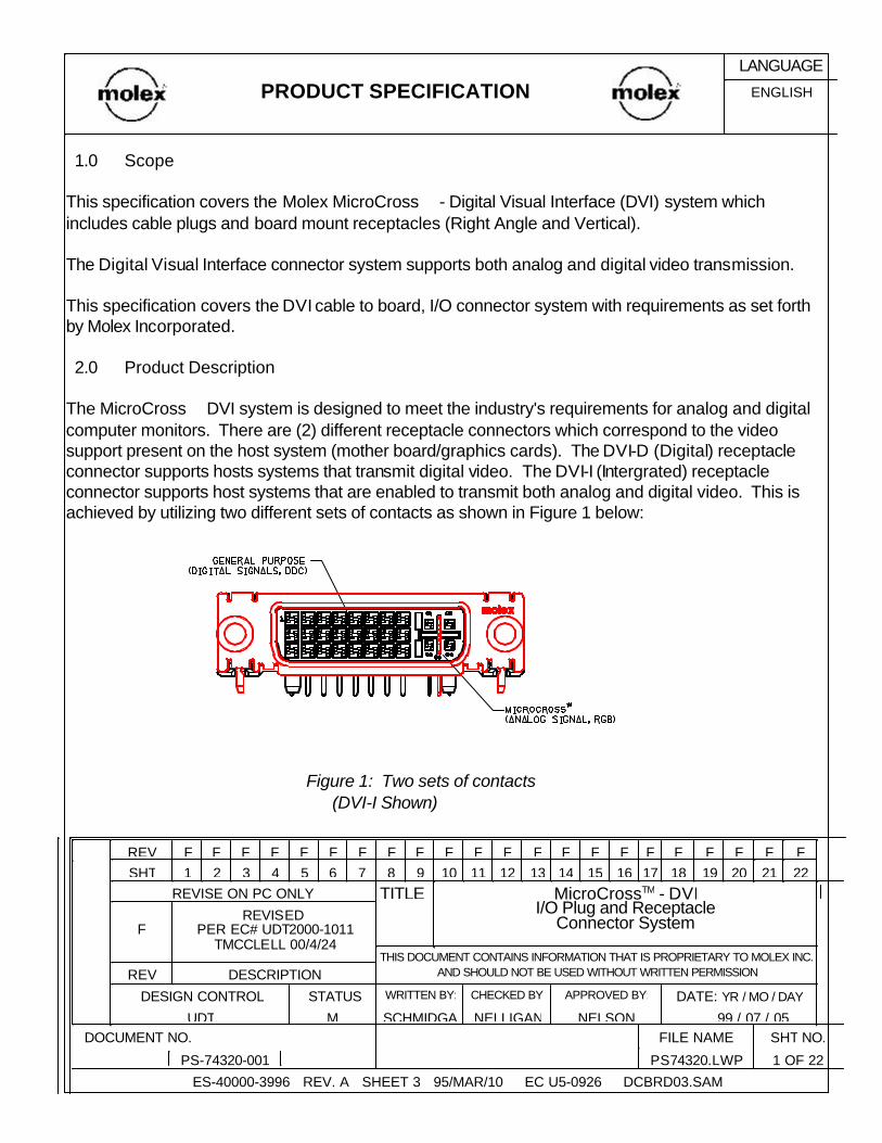
The MicroCross DVI system is designed to meet the industry's requirements for analog and digitalcomputer monitors. There are (2) different receptacle connectors which correspond to the videosupport present on the host system (mother board/graphics cards). The DVI-D (Digital) receptacleconnector supports hosts systems that transmit digital video. The DVI-I (Intergrated) receptacleconnector supports host systems that are enabled to transmit both analog and digital video. This isachieved by utilizing two different sets of contacts as shown in Figure 1 below:
Figure 1: Two sets of contacts (DVI-I Shown)
ES-40000-3996 REV. A SHEET 3 95/MAR/10 EC U5-0926 DCBRD03.SAM
1 OF 22PS74320.LWPPS-74320-001
SHT NO.FILE NAME DOCUMENT NO. 99 / 07 / 05NELSONNELLIGANSCHMIDGAMUDT
DATE: YR / MO / DAYAPPROVED BY:CHECKED BY:WRITTEN BY: STATUS DESIGN CONTROL
DESCRIPTIONREVTHIS DOCUMENT CONTAINS INFORMATION THAT IS PROPRIETARY TO MOLEX INC.
AND SHOULD NOT BE USED WITHOUT WRITTEN PERMISSION
REVISED PER EC# UDT2000-1011
TMCCLELL 00/4/24F
MicroCrossTM - DVII/O Plug and Receptacle
Connector System
TITLEREVISE ON PC ONLY22212019181716151413121110987654321SHTFFFFFFFFFFFFFFFFFFFFFFREV
ENGLISHPRODUCT SPECIFICATIONLANGUAGE

1. General purpose signals:Terminals: 24 circuits on a 0.075 inch/1.91 mm gridSignals: Includes power, grounds, digital and video signals, analog synch lines and DDC
(Display Data Channel) signals.
T.M.D.S. Clock-24Hot Plug Detect16No Connect8T.M.D.S. Clock+23Ground (for +5V)15DDC Data7T.M.D.S. Clock Shield22+5 V Power14DDC Clock6T.M.D.S. Data 5+21T.M.D.S. 3+13T.M.D.S. Data 4+5T.M.D.S. Data 5-20T.M.D.S. Data 3-12T.M.D.S. Data 4-4T.M.D.S. Data 0/5 Shield19T.M.D.S. Data 1/3 Shield11T.M.D.S. Data2/4 Shield3T.M.D.S. Data 0+18T.M.D.S. Data1+10T.M.D.S. Data2+2T.M.D.S. Data 0-17T.M.D.S. Data1-9T.M.D.S. Data2-1Signal AssignmentPinSignal AssignmentPinSignal AssignmentPin
Table 1: Digital-Only Connector Pin AssignmentsSource: Digital Visual Interface Specification, Revision 1.0
2. MicroCross: a) Plug and Receptacle - I - Intergrated analog/digital - see figure 3, sheet 4
Terminals: 4 circuits on a 0.100 inch/2.54 mm grid with a crossing ground plane in between. Signals: High frequency, 75 ohm, analog video
b) Plug and Receptacle - D - Digital Version Terminals: A single key on the plug and corresponding slot on the receptacle.
Signals: The key is used for mechanical polarization only, it does not carry any electrical signals.
ENGLISHPRODUCT SPECIFICATIONLANGUAGE
ES-40000-3996 REV. A SHEET 4 95/MAR/10 EC U5-0926 DCBRD03.SAM2PS74320.LWPPS-74320-001
SHEETFILE NAME DOCUMENT NO.
DESCRIPTIONREVTHIS DOCUMENT CONTAINS INFORMATION THAT IS PROPRIETARY TO MOLEX
INC. AND SHOULD NOT BE USED WITHOUT WRITTEN PERMISSION
SEE SHEET 1F
MiroCrossTM - DVI I/O Plug and Receptacle
Connector System
TITLEREVISE ON PC ONLY

Analog Ground(analog R, G, & B return)
C5Analog Horizontal SyncC4Analog BlueC3Analog GreenC2Analog RedC1T.M.D.S. Clock-24Hot Plug Detect16Analog Vertical Sync8
T.M.D.S. Clock+23Ground(return for +5V, HSync,and VSync)
15DDC Data7T.M.D.S. Clock Shield22+5V Power14DDC Clock6T.M.D.S. Data 5+21T.M.D.S. Data 3+13T.M.D.S. Data 4+5T.M.D.S. Data 5-20T.M.D.S. Data 3-12T.M.D.S. Data 4-4T.M.D.S. Data 0/5 Shield19T.M.D.S. Data 1/3 Shield11T.M.D.S. Data 2/4 Shield3T.M.D.S. Data 0+18T.M.D.S. Data 1+10T.M.D.S. Data 2+2T.M.D.S. Data 0-17T.M.D.S. Data 1-9T.M.D.S. Data 2-1Signal AssignmentPinSignal AssignmentPinSignal AssignmentPin
Table 2: Combined Analog and Digital Connector Pin AssignmentsSource: Digital Visual Interface, Revision 1.0
Additional general specifications are:Plug:
-LFH (Low Force Helix) style contacts-fully shielded RFI/EMI can-grounding detents on mating shell-solder tails for cable termination-positive retention jackscrew: thread 4-40 UNC-2A
Receptacle:-high cycle, dual beam, LFH shrouded contacts-polarization achieved by a "D" shaped housing/shield-single piece shield with integral ground leg-shield protrudes for ESD considerations-solder tails for thru hole board mount-plastic retention pegs-jackposts: # 4-40 UNC-2A&B threads. The recommended application torque setting is 4 in-lbs maximum. To prevent stripping the shield threads while installing the jackposts, it is recommended the jackposts are started by hand or with a lower initial torque driver setting. The engaged threads are rated to hold a minimum of 5 in-lbs of torque.
ENGLISHPRODUCT SPECIFICATIONLANGUAGE
ES-40000-3996 REV. A SHEET 4 95/MAR/10 EC U5-0926 DCBRD03.SAM3PS74320.LWPPS-74320-001
SHEETFILE NAME DOCUMENT NO.
DESCRIPTIONREVTHIS DOCUMENT CONTAINS INFORMATION THAT IS PROPRIETARY TO MOLEX
INC. AND SHOULD NOT BE USED WITHOUT WRITTEN PERMISSION
SEE SHEET 1F
MiroCrossTM - DVI I/O Plug and Receptacle
Connector System
TITLEREVISE ON PC ONLY
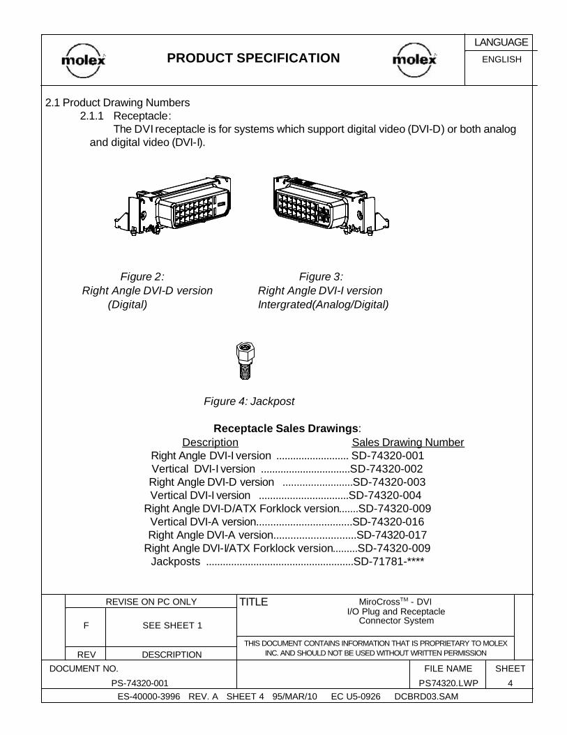
2.1 Product Drawing Numbers2.1.1 Receptacle:
The DVI receptacle is for systems which support digital video (DVI-D) or both analog and digital video (DVI-I).
Figure 2: Figure 3: Right Angle DVI-D version Right Angle DVI-I version
(Digital) Intergrated(Analog/Digital)
Figure 4: Jackpost
Receptacle Sales Drawings:Description Sales Drawing Number
Right Angle DVI-I version .......................... SD-74320-001Vertical DVI-I version ................................SD-74320-002Right Angle DVI-D version .........................SD-74320-003Vertical DVI-I version ................................SD-74320-004
Right Angle DVI-D/ATX Forklock version.......SD-74320-009Vertical DVI-A version..................................SD-74320-016Right Angle DVI-A version.............................SD-74320-017
Right Angle DVI-I/ATX Forklock version.........SD-74320-009Jackposts .....................................................SD-71781-****
ENGLISHPRODUCT SPECIFICATIONLANGUAGE
ES-40000-3996 REV. A SHEET 4 95/MAR/10 EC U5-0926 DCBRD03.SAM4PS74320.LWPPS-74320-001
SHEETFILE NAME DOCUMENT NO.
DESCRIPTIONREVTHIS DOCUMENT CONTAINS INFORMATION THAT IS PROPRIETARY TO MOLEX
INC. AND SHOULD NOT BE USED WITHOUT WRITTEN PERMISSION
SEE SHEET 1F
MiroCrossTM - DVI I/O Plug and Receptacle
Connector System
TITLEREVISE ON PC ONLY

2.1.2 DVI PlugThe DVI plug is for systems which use analog or digital video. The analog DVI plug
shown below supports analog video transmission from the host to the display.
Figure 5:
Analog Version
DVI Plug Sales Drawings (Analog version):
Description Sales Drawing NumberPlug Subassembly ....................... SD-74323-003EMI Can Kit....... ............................. SD-88789-9333
(Kit includes upper and lower shields)Crimp Ferrule ............................... SD-73772-000 Boot ............................................... SD-888743-230XJackscrew with cap ........................ SD-88780-6005
ENGLISHPRODUCT SPECIFICATIONLANGUAGE
ES-40000-3996 REV. A SHEET 4 95/MAR/10 EC U5-0926 DCBRD03.SAM5PS74320.LWPPS-74320-001
SHEETFILE NAME DOCUMENT NO.
DESCRIPTIONREVTHIS DOCUMENT CONTAINS INFORMATION THAT IS PROPRIETARY TO MOLEX
INC. AND SHOULD NOT BE USED WITHOUT WRITTEN PERMISSION
SEE SHEET 1F
MiroCrossTM - DVI I/O Plug and Receptacle
Connector System
TITLEREVISE ON PC ONLY
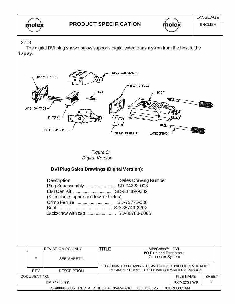
2.1.3The digital DVI plug shown below supports digital video transmission from the host to the
display.
Figure 6: Digital Version
DVI Plug Sales Drawings (Digital Version):
Description Sales Drawing NumberPlug Subassembly ....................... SD-74323-003EMI Can Kit .................................. SD-88789-9332(Kit includes upper and lower shields)Crimp Ferrule ............................... SD-73772-000 Boot ............................................... SD-88743-220XJackscrew with cap ........................ SD-88780-6006
ENGLISHPRODUCT SPECIFICATIONLANGUAGE
ES-40000-3996 REV. A SHEET 4 95/MAR/10 EC U5-0926 DCBRD03.SAM6PS74320.LWPPS-74320-001
SHEETFILE NAME DOCUMENT NO.
DESCRIPTIONREVTHIS DOCUMENT CONTAINS INFORMATION THAT IS PROPRIETARY TO MOLEX
INC. AND SHOULD NOT BE USED WITHOUT WRITTEN PERMISSION
SEE SHEET 1F
MiroCrossTM - DVI I/O Plug and Receptacle
Connector System
TITLEREVISE ON PC ONLY

2.2 Dimensions, Materials, Plating, and Markings2.2.1 Board Layout
Figure 7: Recommended PCB Layout for Right Angle DVI-I Receptacle
Figure 8: Recommended PCB Layout for Vertical DVI-I Receptacle
ENGLISHPRODUCT SPECIFICATIONLANGUAGE
ES-40000-3996 REV. A SHEET 4 95/MAR/10 EC U5-0926 DCBRD03.SAM7PS74320.LWPPS-74320-001
SHEETFILE NAME DOCUMENT NO.
DESCRIPTIONREVTHIS DOCUMENT CONTAINS INFORMATION THAT IS PROPRIETARY TO MOLEX
INC. AND SHOULD NOT BE USED WITHOUT WRITTEN PERMISSION
SEE SHEET 1F
MiroCrossTM - DVI I/O Plug and Receptacle
Connector System
TITLEREVISE ON PC ONLY

Figure 9: Recommended PCB Layout for Right Angle DVI-D Receptacle
Figure 10: Recommended PCB Layout for Vertical DVI-D Receptacle
ENGLISHPRODUCT SPECIFICATIONLANGUAGE
ES-40000-3996 REV. A SHEET 4 95/MAR/10 EC U5-0926 DCBRD03.SAM8PS74320.LWPPS-74320-001
SHEETFILE NAME DOCUMENT NO.
DESCRIPTIONREVTHIS DOCUMENT CONTAINS INFORMATION THAT IS PROPRIETARY TO MOLEX
INC. AND SHOULD NOT BE USED WITHOUT WRITTEN PERMISSION
SEE SHEET 1F
MiroCrossTM - DVI I/O Plug and Receptacle
Connector System
TITLEREVISE ON PC ONLY

Figure11: Recommended PCB Layout for Right Angle DVI-D/ATX Fork Lock Receptacle
2.2.3 Panel cut-out
Figure 12: Recommended Panel Cutout for Receptacle Connector
ENGLISHPRODUCT SPECIFICATIONLANGUAGE
ES-40000-3996 REV. A SHEET 4 95/MAR/10 EC U5-0926 DCBRD03.SAM9PS74320.LWPPS-74320-001
SHEETFILE NAME DOCUMENT NO.
DESCRIPTIONREVTHIS DOCUMENT CONTAINS INFORMATION THAT IS PROPRIETARY TO MOLEX
INC. AND SHOULD NOT BE USED WITHOUT WRITTEN PERMISSION
SEE SHEET 1F
MiroCrossTM - DVI I/O Plug and Receptacle
Connector System
TITLEREVISE ON PC ONLY
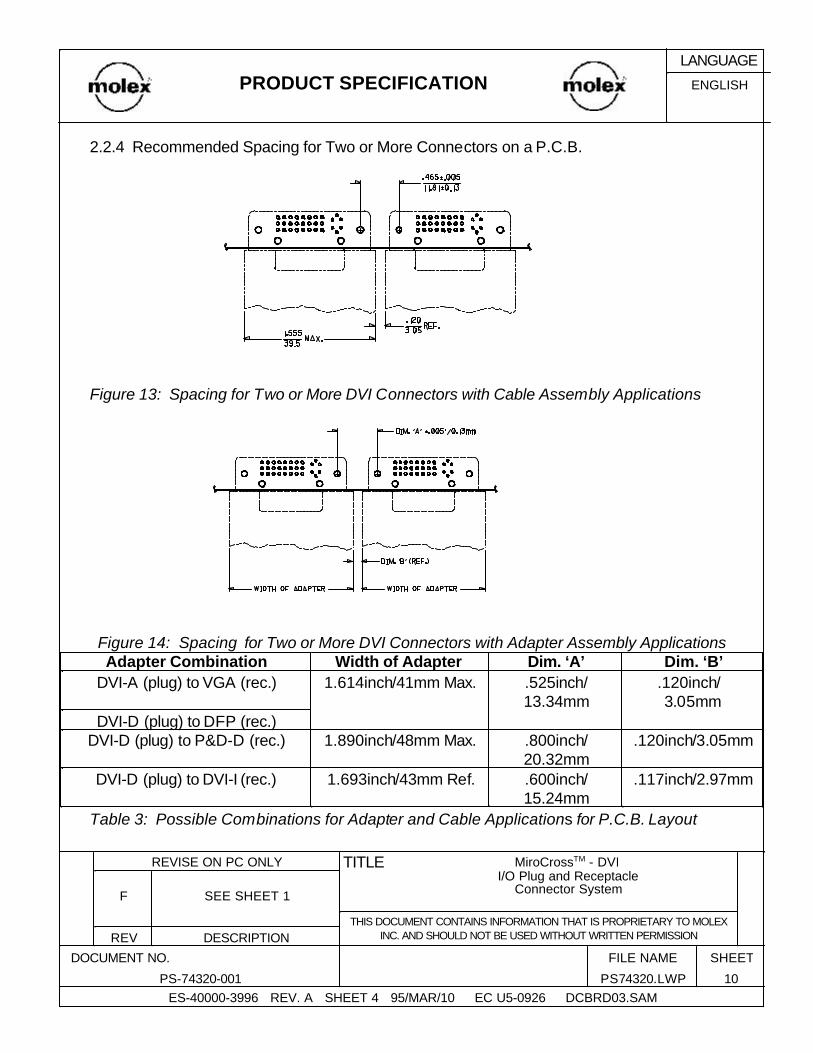
2.2.4 Recommended Spacing for Two or More Connectors on a P.C.B.
Figure 13: Spacing for Two or More DVI Connectors with Cable Assembly Applications
Figure 14: Spacing for Two or More DVI Connectors with Adapter Assembly Applications
.117inch/2.97mm.600inch/15.24mm
1.693inch/43mm Ref.DVI-D (plug) to DVI-I (rec.)
.120inch/3.05mm.800inch/20.32mm
1.890inch/48mm Max.DVI-D (plug) to P&D-D (rec.)DVI-D (plug) to DFP (rec.)
.120inch/ 3.05mm
.525inch/13.34mm
1.614inch/41mm Max.DVI-A (plug) to VGA (rec.)Dim. ‘B’Dim. ‘A’Width of Adapter Adapter Combination
Table 3: Possible Combinations for Adapter and Cable Applications for P.C.B. Layout
ENGLISHPRODUCT SPECIFICATIONLANGUAGE
ES-40000-3996 REV. A SHEET 4 95/MAR/10 EC U5-0926 DCBRD03.SAM10PS74320.LWPPS-74320-001
SHEETFILE NAME DOCUMENT NO.
DESCRIPTIONREVTHIS DOCUMENT CONTAINS INFORMATION THAT IS PROPRIETARY TO MOLEX
INC. AND SHOULD NOT BE USED WITHOUT WRITTEN PERMISSION
SEE SHEET 1F
MiroCrossTM - DVI I/O Plug and Receptacle
Connector System
TITLEREVISE ON PC ONLY
2.2.4 MaterialsHousings: High temp glass-filled thermoplastic, black or white/natural, UL94 V-0 Tail Aligner:High temp glass-filled thermoplastic, black or white/natural, UL94 V-0
Receptacle Terminals: Copper alloy. Plug Terminals: Brass. Receptacle Ground Terminal: Copper Alloy Plug Key: Copper Alloy Plug Ground Blade: Brass Shields: Steel
2.2.4 PlatingTerminals (0.075inch/1.91mm and 0.050inch/2.54mm grid): Option #1 -Select gold flash in contact area and 100 microinch / 2.50
micrometer minimum select tin/lead in solder tail area over 50 microinch / 1.27 micrometer nickel overall. Option #2 - 30 microinch / 0.75 micrometer minimum select gold and 100 microinch / 2.50 micrometer minimum select tin/lead in solder tail area over 50 microinch / 1.27 micrometer nickel overall.
Microcross Ground: 30 microinch / 0.75 micrometer minimum select gold in contact area and; 100 microinch / 2.50 micrometer minimum select tin-lead in solder tail area
over 50 microinch / 1.27 micrometer minimum nickel overall.
Key: Select gold flash over 40 microinch / 1.00 micrometer nickel overall.
Ground Blade: Select gold flash over 50 microinch / 1.27 micrometer nickel overall in contact area and 150 microinch / 3.75 micrometer tin/lead solder area.
Shields:150 microinch / 3.75 micrometer minimum bright tin over;50 microinch / 1.27 micrometer nickel; over copper flash overall.
ENGLISHPRODUCT SPECIFICATIONLANGUAGE
ES-40000-3996 REV. A SHEET 4 95/MAR/10 EC U5-0926 DCBRD03.SAM11PS74320.LWPPS-74320-001
SHEETFILE NAME DOCUMENT NO.
DESCRIPTIONREVTHIS DOCUMENT CONTAINS INFORMATION THAT IS PROPRIETARY TO MOLEX
INC. AND SHOULD NOT BE USED WITHOUT WRITTEN PERMISSION
SEE SHEET 1F
MiroCrossTM - DVI I/O Plug and Receptacle
Connector System
TITLEREVISE ON PC ONLY

2.2.5 MarkingsAll assemblies will contain circuit identification markings as well as the “Molex” or
“Mlx” on the front of the shell. Refer to the appropriate sales drawings for specific marking information.
2.3 Safety Agency Approvals UL File Number ............. E29179, Volume 10, Section 12 CSA File Number .......... LR19980
3.0 Applicable Documents and Specifications3.1 All documents referenced shall be of the latest revision. The order of precedence detailing requirements of this specification is as follows:
1. Product Drawings 2. This specification
3.2 Reference Documents3.2.1 EIA RS-364-(06,09,13,17,18,20,21,23,27,28,31,32,41,46,65,67,70,90) Electronic
Industries Association, Recommended Standard3.2.2 IEC-801-2 International Electrotechnical Commission, Electrostatic Discharge
Requirements3.2.3 MIL STD-202: Test methods for electronics and electrical component parts3.2.4 Molex PS-74320-9999 Application Specification, DVI Plug Cable Assembly3.2.5 Molex ES-74320-9998 Termination Specification, DVI Cable Assemblies3.2.6 Molex PS-74320-9997 Cable Assembly Specification3.2.7 UL 94: Tests for flammability of plastics materials
4.0 Ratings4.1 Voltage
40 Volts AC (RMS)
4.2 Current 1.5 Amps per circuit. 30 OC maximum temperature rise and 55 OC maximum ambient per EIA-364-70.
4.3 Temperature Operating: - 20 OC to + 85 OC
Nonoperating: - 20 OC to + 85 OC
ENGLISHPRODUCT SPECIFICATIONLANGUAGE
ES-40000-3996 REV. A SHEET 4 95/MAR/10 EC U5-0926 DCBRD03.SAM12PS74320.LWPPS-74320-001
SHEETFILE NAME DOCUMENT NO.
DESCRIPTIONREVTHIS DOCUMENT CONTAINS INFORMATION THAT IS PROPRIETARY TO MOLEX
INC. AND SHOULD NOT BE USED WITHOUT WRITTEN PERMISSION
SEE SHEET 1F
MiroCrossTM - DVI I/O Plug and Receptacle
Connector System
TITLEREVISE ON PC ONLY

5.0 Performance
5.1 Electrical Performance
100 ohms +/-15%Risetime = 330 pS (10%-90%)S:G ratio per DVI pin designation
Differential MeasurementSpecimen Environment Impedance = 100 ohm
differentialSource-side receptacle connector mounted on a
controlled impendance pcb fixtureper ANSI/EIA-364-108 draft Proposal
T.M.D.S. SignalsTime Domain Impedance
No evidence of discharge to contacts at8kV. Discharge to the shell is acceptable.
Test unmated from 1 kV to 8kV in 1 kV stepsusing 8mm ball prob per IEC 801-2
Contact discharge to shellAir discharge perpendicular to shell
Air discharge at angle to shell
Electrostatic Discharge
40 Volts AC (rms) continuous maximum,on any signal pin with respect to the shield
Applied Voltage Rating
3.0 A maximumMaximum ambient = 55 degree CMaximum temperature change = 85 degree C
per ANSI/EIA-364-70, TP-70
Contact Current Rating
No flashover, No sparkover, No excessleakage, No Breakdown
Test voltage = 500 Volts DC +/-50 VUnmated and Unmounted
per ANSI/EIA 364-20, Method CBarometric pressure of 15 psi
Dielectric WithstandingVoltage
1Gigaohm Minimum between adjacentcontacts and contacts and shell
Test voltage = 500 Volts DC +/- 50 VUnmated and Unmounted
per ANSI/EIA 364-21, Method C
Insulation Resistance
50 milliohm maximum initial50 milliohm maximum change from initial
reading
Bulk resistance measured between ground legon receptacle shield and the plug cable braid. Test current=100mA; Test voltage=5 Volts DC
open circuit maximumper ANSI/EIA-364-06A-83
Shell Resistance
20 milliohm maximum, initial per contactmated pair
10 milliohm maximum change from initialreading per contact mated pair
Bulk resistance measured between plug soldertails and receptacle solder tails
per ANSI/EIA-364-23
Contact ResistanceREQUIREMENTTEST CONDITIONITEM
ENGLISHPRODUCT SPECIFICATIONLANGUAGE
ES-40000-3996 REV. A SHEET 4 95/MAR/10 EC U5-0926 DCBRD03.SAM13PS74320.LWPPS-74320-001
SHEETFILE NAME DOCUMENT NO.
DESCRIPTIONREVTHIS DOCUMENT CONTAINS INFORMATION THAT IS PROPRIETARY TO MOLEX
INC. AND SHOULD NOT BE USED WITHOUT WRITTEN PERMISSION
SEE SHEET 1F
MiroCrossTM - DVI I/O Plug and Receptacle
Connector System
TITLEREVISE ON PC ONLY

140pS Maximum(Note: Converted bandwidth using
BW=0.35/t rise yields 2.5 GHz)
S:G ratio per DVI pin designationSingle-ended Measurement
Specimen Environment Impedance = 75 ohmsingle-ended
Source-side receptacle connector is mounted ona controlled impedance pcb fixture and the loadside plug connector is terminated to semi-rigid
coax.per ANSI/EIA-364-102
Analog RGBCoaxial Signals
Rise Time Degradation
3% MaximumRisetime = 700 pS (10%-90%)S:G ratio per DVI pin designation
Single-ended MeasurementSpecimen Enviroment Impedance = 75 ohm
single-endedSource-side receptacle connector is mounted ona controlled impedance pcb fixture and the loadside plug connector is terminated to semi-rigid
coax.(1) Driven line and (1) victim line
per ANSI/EIA-364-90 Draft Proposal
Analog RGBCoaxial Signals
TimeDomain Crosstalk:
(FEXT)
75 ohms +/-10%Risetime = 700 pS (10%-90%)S:G ratio per DVI pin designation
Single-ended MeasurementSpecimen Enviroment Impedance = 75 ohm
single-endedSource-side receptacle connector mounted on a
controlled impedence pcb fixtureper ANSI/EIA-364-108 Draft Proposal
Analog RGBCoaxial Signals
TimeDomain Impedance
160 pS Maximum(Note: Converted bandwidth usingBW=0.35/t rise yields 2.2 GHz)
S:G ratio per DVI pin designationDifferential Measurement
Specimen Environment Impedance = 100 ohmdifferential
Source-side receptacle and the load side plugconnector are mounted on a controlled
impedance pcb fixtureper ANSI/EIA-364-102 Draft Proposal
T.M.D.S. SignalsRise Time Degradation
5% MaximumRisetime = 330 pS (10%-90%)S:G ratio per DVI pin designation
Differential MeasurementSpecimen Environment Impedance = 100 ohm
differentialSource-side receptacle and the load side plug
connector are mounted on a controlledimpedance pcb fixture
(1) Driven pair and (1) victim pairper ANSI/EIA-364-90 Draft Proposal
T.M.D.S. SignalsTime Domain
Crosstalk:FEXT
ENGLISHPRODUCT SPECIFICATIONLANGUAGE
ES-40000-3996 REV. A SHEET 4 95/MAR/10 EC U5-0926 DCBRD03.SAM14PS74320.LWPPS-74320-001
SHEETFILE NAME DOCUMENT NO.
DESCRIPTIONREVTHIS DOCUMENT CONTAINS INFORMATION THAT IS PROPRIETARY TO MOLEX
INC. AND SHOULD NOT BE USED WITHOUT WRITTEN PERMISSION
SEE SHEET 1F
MiroCrossTM - DVI I/O Plug and Receptacle
Connector System
TITLEREVISE ON PC ONLY

5.2 Mechanical Performance
5.0 in-lbs minimumMounted to panel; Test to failure; Tightenjackposts with torque gage until threads are
stripped and jackpost turns freely
Thread Torque
.050" pitch terminals: 75 grams typical
.075" pitch terminals: 90 grams typical Ground Plane: 100 grams typical
For reference onlyNormal Force
No discontinuities greater than 1microsecond allowed during flexing on
contacts or shields per EIA-364-46Dielectric Withstanding Voltage and
Insulation Resistance tested perrequirements of section 5.1
100 cycles in each of 2 planesDimension X=3.7x Cable Diameterper ANSI/EIA 364-41, Condition I
Cable Flex
10.0 lbf (4.5 kgf) maximumBoard Insertion Force
No discontinuities greater than 1microsecond
Test for cable strain relief & terminationintergrity. Cable subjected to 25.0 lbf (11.3 kgf)
static load for one minute while monitoringcontinuity. Isolate plug & receptacle interface
from load.
Cable Pullout Force
No discontinuities at 1 microsecond orlonger (each contact) when continuity is
tested per EIA-364-46
Per ANSI/EIA 364-27, Condition A(specified pulse)
Shock(Mechanical)
No discontinuities at 1 microsecond orlonger (each contact) when continuity is
tested per EIA-364-46
15 minutes / axisper ANSI/EIA 364-28, Method 5A
Vibration
Contact Resistance per EIA 364-23: 10milliohm maximum change from initial per
contact pairAll samples to be mated
Shell Resistance: 50 milliohm maximum(change from initial reading)
Automatic cycling: 100 cycles per ANSI/EIA 364-09
at 100 +/- 50 cycles per hour
Durability1.0 lbf (0.45 kgf) minimumIndividual keyPlug Key Retention
1.0 lbf (0.45 kgf) minimumIndividual contactReceptacle ContactRetention
1.0 lbf (0.45 kgf) minimumIndividual contactPlug Contact Retention
2.2 lbf (1.0 kgf) minimum 8.8 lbf (4.0 kgf) maximum
Mated pair per ANSI/EIA 364-13Withdraw speed: 1inch (25mm) per minute
Unmating Force
10.0 lbf (4.5 kgf) maximumOne pair per ANSI/EIA 364-13Insertion speed: 1inch (25mm) per minute
Mating ForceREQUIREMENTTEST CONDITIONITEM
ENGLISHPRODUCT SPECIFICATIONLANGUAGE
ES-40000-3996 REV. A SHEET 4 95/MAR/10 EC U5-0926 DCBRD03.SAM15PS74320.LWPPS-74320-001
SHEETFILE NAME DOCUMENT NO.
DESCRIPTIONREVTHIS DOCUMENT CONTAINS INFORMATION THAT IS PROPRIETARY TO MOLEX
INC. AND SHOULD NOT BE USED WITHOUT WRITTEN PERMISSION
SEE SHEET 1F
MiroCrossTM - DVI I/O Plug and Receptacle
Connector System
TITLEREVISE ON PC ONLY

5.3 Environmental Performance
-20 degree C to +85 degree CNon-OperatingTemperature Rating-20 degree C to +85 degree COperatingTemperature Rating
95% minimum coveragePer MIL-STD-202, Method 208Solderability
No visual damage to insulatorDip connector solder tails to board for 10 secondsSolder Temp = 260 +/- 5 OC
Resistance to SolderHeat
30 OC maximum temperature risePer ANSI/EIA 364-70Temperature Rise
Contact Resistance: 10 milliohmmaximum change from initial per
contact pairAll samples to be mated
Shell Resistance: 50 milliohmmaximum change from initial per
contact pairper EIA-364-23
105 OC for 250 hoursMated per ANSI/EIA 364-17, Condition 4,
Method A.
Thermal Aging
Contact Resistance: 10 milliohmmaximum change from initial per
contact pairAll samples to be mated
Shell Resistance: 50 milliohmmaximum change from initial
per EIA-364-23
ANSI/EIA 364-31, Conditions A and BMethod III, omit 7A and 7B
Humidity(Cyclic)
Contact Resistance: 10 milliohmmaximum change from initial per
contact pairAll samples to be mated
Shell Resistance: 50 milliohmmaximum change from initial
per EIA-364-23
10 cycles Mated/Unmated per ANSI/EIA 364-32,Condition I
Thermal ShockREQUIREMENTTEST CONDITIONITEM
ENGLISHPRODUCT SPECIFICATIONLANGUAGE
ES-40000-3996 REV. A SHEET 4 95/MAR/10 EC U5-0926 DCBRD03.SAM16PS74320.LWPPS-74320-001
SHEETFILE NAME DOCUMENT NO.
DESCRIPTIONREVTHIS DOCUMENT CONTAINS INFORMATION THAT IS PROPRIETARY TO MOLEX
INC. AND SHOULD NOT BE USED WITHOUT WRITTEN PERMISSION
SEE SHEET 1F
MiroCrossTM - DVI I/O Plug and Receptacle
Connector System
TITLEREVISE ON PC ONLY
6.0 Packaging6.1 Receptacles:
All receptacles are packaged in trays. For specific packaging information, refer to PK-74320-001 for right angle receptacles and PK-74320-002 for vertical receptacles.
7.0 Other Information7.1 Test Sequences
ENGLISHPRODUCT SPECIFICATIONLANGUAGE
ES-40000-3996 REV. A SHEET 4 95/MAR/10 EC U5-0926 DCBRD03.SAM17PS74320.LWPPS-74320-001
SHEETFILE NAME DOCUMENT NO.
DESCRIPTIONREVTHIS DOCUMENT CONTAINS INFORMATION THAT IS PROPRIETARY TO MOLEX
INC. AND SHOULD NOT BE USED WITHOUT WRITTEN PERMISSION
SEE SHEET 1F
MiroCrossTM - DVI I/O Plug and Receptacle
Connector System
TITLEREVISE ON PC ONLY
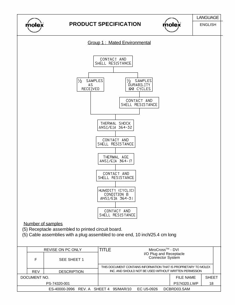
Group 1 : Mated Environmental
Number of samples (5) Receptacle assembled to printed circuit board. (5) Cable assemblies with a plug assembled to one end, 10 inch/25.4 cm long
ENGLISHPRODUCT SPECIFICATIONLANGUAGE
ES-40000-3996 REV. A SHEET 4 95/MAR/10 EC U5-0926 DCBRD03.SAM18PS74320.LWPPS-74320-001
SHEETFILE NAME DOCUMENT NO.
DESCRIPTIONREVTHIS DOCUMENT CONTAINS INFORMATION THAT IS PROPRIETARY TO MOLEX
INC. AND SHOULD NOT BE USED WITHOUT WRITTEN PERMISSION
SEE SHEET 1F
MiroCrossTM - DVI I/O Plug and Receptacle
Connector System
TITLEREVISE ON PC ONLY

Group 2 : Mated Mechanical
Number of Samples: (2) Receptacles, assembled to printed circuit board.
(2) Cable assemblies with a plug assembled to one end, 10 inch/25.4 cm long.
Note: Connector is to be mounted on a fixture that simulates the typical application. The receptacle connector shall be mounted to a panel, per the receptacle panel cutout shown in Figure 12, which is permanently affixed to the fixture. The plug shall be mated to the
receptacle with jackscrews fully engaged and the other end of the cable shall be permanently clamped to the fixture, 3 inches from connector face.
ENGLISHPRODUCT SPECIFICATIONLANGUAGE
ES-40000-3996 REV. A SHEET 4 95/MAR/10 EC U5-0926 DCBRD03.SAM19PS74320.LWPPS-74320-001
SHEETFILE NAME DOCUMENT NO.
DESCRIPTIONREVTHIS DOCUMENT CONTAINS INFORMATION THAT IS PROPRIETARY TO MOLEX
INC. AND SHOULD NOT BE USED WITHOUT WRITTEN PERMISSION
SEE SHEET 1F
MiroCrossTM - DVI I/O Plug and Receptacle
Connector System
TITLEREVISE ON PC ONLY

Group 3 : Mated Mechanical
Number of Samples:(2) Receptacles, assembled to printed circuit board.(2) Cable assemblies with a plug assembled to one end, 10 inch/25.4 cm long.
ENGLISHPRODUCT SPECIFICATIONLANGUAGE
ES-40000-3996 REV. A SHEET 4 95/MAR/10 EC U5-0926 DCBRD03.SAM20PS74320.LWPPS-74320-001
SHEETFILE NAME DOCUMENT NO.
DESCRIPTIONREVTHIS DOCUMENT CONTAINS INFORMATION THAT IS PROPRIETARY TO MOLEX
INC. AND SHOULD NOT BE USED WITHOUT WRITTEN PERMISSION
SEE SHEET 1F
MiroCrossTM - DVI I/O Plug and Receptacle
Connector System
TITLEREVISE ON PC ONLY
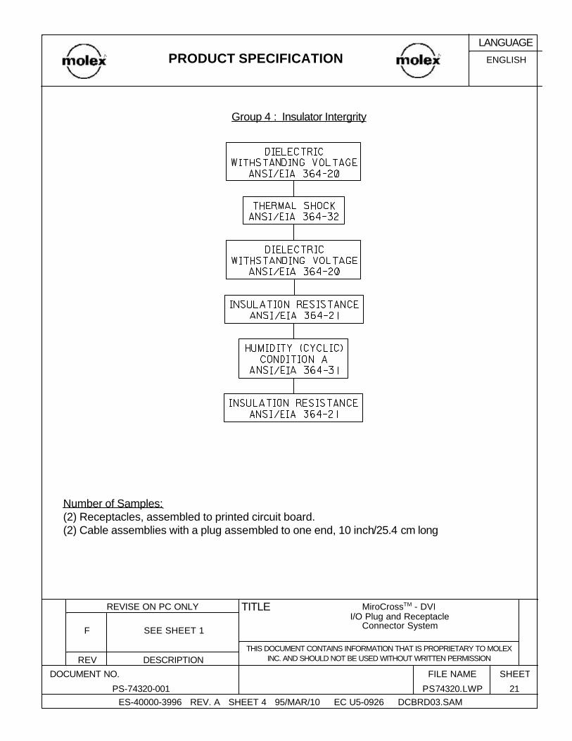
Group 4 : Insulator Intergrity
Number of Samples:(2) Receptacles, assembled to printed circuit board.(2) Cable assemblies with a plug assembled to one end, 10 inch/25.4 cm long
ENGLISHPRODUCT SPECIFICATIONLANGUAGE
ES-40000-3996 REV. A SHEET 4 95/MAR/10 EC U5-0926 DCBRD03.SAM21PS74320.LWPPS-74320-001
SHEETFILE NAME DOCUMENT NO.
DESCRIPTIONREVTHIS DOCUMENT CONTAINS INFORMATION THAT IS PROPRIETARY TO MOLEX
INC. AND SHOULD NOT BE USED WITHOUT WRITTEN PERMISSION
SEE SHEET 1F
MiroCrossTM - DVI I/O Plug and Receptacle
Connector System
TITLEREVISE ON PC ONLY
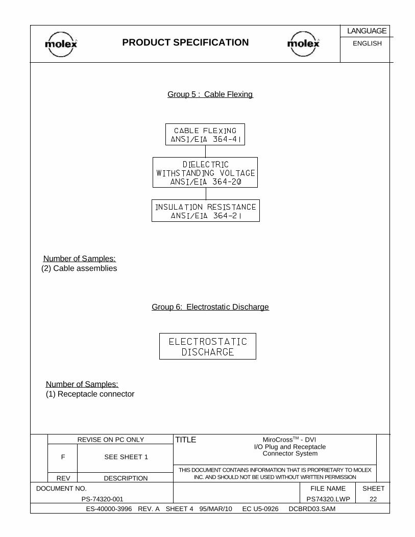
Group 5 : Cable Flexing
Number of Samples: (2) Cable assemblies
Group 6: Electrostatic Discharge
Number of Samples:(1) Receptacle connector
ENGLISHPRODUCT SPECIFICATIONLANGUAGE
ES-40000-3996 REV. A SHEET 4 95/MAR/10 EC U5-0926 DCBRD03.SAM22PS74320.LWPPS-74320-001
SHEETFILE NAME DOCUMENT NO.
DESCRIPTIONREVTHIS DOCUMENT CONTAINS INFORMATION THAT IS PROPRIETARY TO MOLEX
INC. AND SHOULD NOT BE USED WITHOUT WRITTEN PERMISSION
SEE SHEET 1F
MiroCrossTM - DVI I/O Plug and Receptacle
Connector System
TITLEREVISE ON PC ONLY